Dual Band Square Planar Dipole Antennas with … Band Square Planar Dipole Antennas with...
10
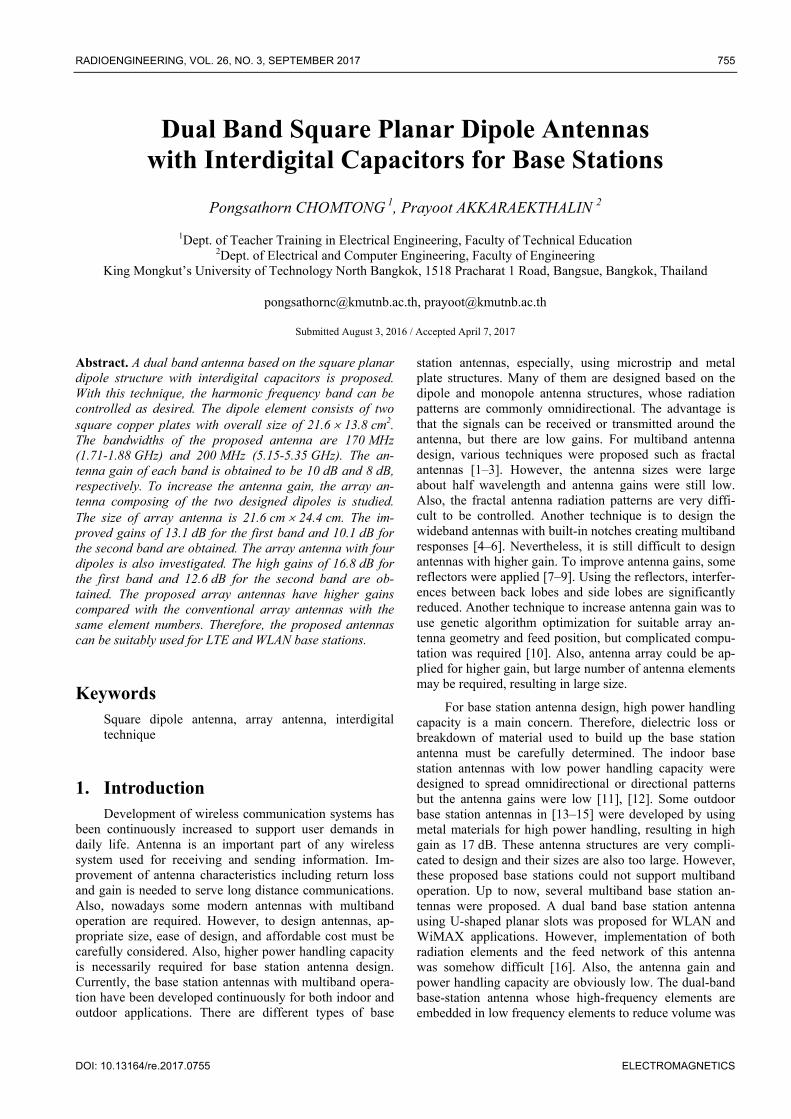
RADIOENGINEERING, VOL. 26, NO. 3, SEPTEMBER 2017 755 DOI: 10.13164/re.2017.0755 ELECTROMAGNETICS Dual Band Square Planar Dipole Antennas with Interdigital Capacitors for Base Stations Pongsathorn CHOMTONG 1 , Prayoot AKKARAEKTHALIN 2 1 Dept. of Teacher Training in Electrical Engineering, Faculty of Technical Education 2 Dept. of Electrical and Computer Engineering, Faculty of Engineering King Mongkut’s University of Technology North Bangkok, 1518 Pracharat 1 Road, Bangsue, Bangkok, Thailand [email protected], [email protected] Submitted August 3, 2016 / Accepted April 7, 2017 Abstract. A dual band antenna based on the square planar dipole structure with interdigital capacitors is proposed. With this technique, the harmonic frequency band can be controlled as desired. The dipole element consists of two square copper plates with overall size of 21.6 13.8 cm 2 . The bandwidths of the proposed antenna are 170 MHz (1.71-1.88 GHz) and 200 MHz (5.15-5.35 GHz). The an- tenna gain of each band is obtained to be 10 dB and 8 dB, respectively. To increase the antenna gain, the array an- tenna composing of the two designed dipoles is studied. The size of array antenna is 21.6 cm 24.4 cm. The im- proved gains of 13.1 dB for the first band and 10.1 dB for the second band are obtained. The array antenna with four dipoles is also investigated. The high gains of 16.8 dB for the first band and 12.6 dB for the second band are ob- tained. The proposed array antennas have higher gains compared with the conventional array antennas with the same element numbers. Therefore, the proposed antennas can be suitably used for LTE and WLAN base stations. Keywords Square dipole antenna, array antenna, interdigital technique 1. Introduction Development of wireless communication systems has been continuously increased to support user demands in daily life. Antenna is an important part of any wireless system used for receiving and sending information. Im- provement of antenna characteristics including return loss and gain is needed to serve long distance communications. Also, nowadays some modern antennas with multiband operation are required. However, to design antennas, ap- propriate size, ease of design, and affordable cost must be carefully considered. Also, higher power handling capacity is necessarily required for base station antenna design. Currently, the base station antennas with multiband opera- tion have been developed continuously for both indoor and outdoor applications. There are different types of base station antennas, especially, using microstrip and metal plate structures. Many of them are designed based on the dipole and monopole antenna structures, whose radiation patterns are commonly omnidirectional. The advantage is that the signals can be received or transmitted around the antenna, but there are low gains. For multiband antenna design, various techniques were proposed such as fractal antennas [1–3]. However, the antenna sizes were large about half wavelength and antenna gains were still low. Also, the fractal antenna radiation patterns are very diffi- cult to be controlled. Another technique is to design the wideband antennas with built-in notches creating multiband responses [4–6]. Nevertheless, it is still difficult to design antennas with higher gain. To improve antenna gains, some reflectors were applied [7–9]. Using the reflectors, interfer- ences between back lobes and side lobes are significantly reduced. Another technique to increase antenna gain was to use genetic algorithm optimization for suitable array an- tenna geometry and feed position, but complicated compu- tation was required [10]. Also, antenna array could be ap- plied for higher gain, but large number of antenna elements may be required, resulting in large size. For base station antenna design, high power handling capacity is a main concern. Therefore, dielectric loss or breakdown of material used to build up the base station antenna must be carefully determined. The indoor base station antennas with low power handling capacity were designed to spread omnidirectional or directional patterns but the antenna gains were low [11], [12]. Some outdoor base station antennas in [13–15] were developed by using metal materials for high power handling, resulting in high gain as 17 dB. These antenna structures are very compli- cated to design and their sizes are also too large. However, these proposed base stations could not support multiband operation. Up to now, several multiband base station an- tennas were proposed. A dual band base station antenna using U-shaped planar slots was proposed for WLAN and WiMAX applications. However, implementation of both radiation elements and the feed network of this antenna was somehow difficult [16]. Also, the antenna gain and power handling capacity are obviously low. The dual-band base-station antenna whose high-frequency elements are embedded in low frequency elements to reduce volume was
Transcript of Dual Band Square Planar Dipole Antennas with … Band Square Planar Dipole Antennas with...
RADIOENGINEERING, VOL. 26, NO. 3, SEPTEMBER 2017 755
DOI: 10.13164/re.2017.0755 ELECTROMAGNETICS
Dual Band Square Planar Dipole Antennas with Interdigital Capacitors for Base Stations
Pongsathorn CHOMTONG 1, Prayoot AKKARAEKTHALIN 2
1Dept. of Teacher Training in Electrical Engineering, Faculty of Technical Education 2Dept. of Electrical and Computer Engineering, Faculty of Engineering
King Mongkut’s University of Technology North Bangkok, 1518 Pracharat 1 Road, Bangsue, Bangkok, Thailand
[email protected], [email protected]
Submitted August 3, 2016 / Accepted April 7, 2017
Abstract. A dual band antenna based on the square planar dipole structure with interdigital capacitors is proposed. With this technique, the harmonic frequency band can be controlled as desired. The dipole element consists of two square copper plates with overall size of 21.6 13.8 cm2. The bandwidths of the proposed antenna are 170 MHz (1.71-1.88 GHz) and 200 MHz (5.15-5.35 GHz). The an-tenna gain of each band is obtained to be 10 dB and 8 dB, respectively. To increase the antenna gain, the array an-tenna composing of the two designed dipoles is studied. The size of array antenna is 21.6 cm 24.4 cm. The im-proved gains of 13.1 dB for the first band and 10.1 dB for the second band are obtained. The array antenna with four dipoles is also investigated. The high gains of 16.8 dB for the first band and 12.6 dB for the second band are ob-tained. The proposed array antennas have higher gains compared with the conventional array antennas with the same element numbers. Therefore, the proposed antennas can be suitably used for LTE and WLAN base stations.
Keywords Square dipole antenna, array antenna, interdigital technique
1. Introduction Development of wireless communication systems has
been continuously increased to support user demands in daily life. Antenna is an important part of any wireless system used for receiving and sending information. Im-provement of antenna characteristics including return loss and gain is needed to serve long distance communications. Also, nowadays some modern antennas with multiband operation are required. However, to design antennas, ap-propriate size, ease of design, and affordable cost must be carefully considered. Also, higher power handling capacity is necessarily required for base station antenna design. Currently, the base station antennas with multiband opera-tion have been developed continuously for both indoor and outdoor applications. There are different types of base
station antennas, especially, using microstrip and metal plate structures. Many of them are designed based on the dipole and monopole antenna structures, whose radiation patterns are commonly omnidirectional. The advantage is that the signals can be received or transmitted around the antenna, but there are low gains. For multiband antenna design, various techniques were proposed such as fractal antennas [1–3]. However, the antenna sizes were large about half wavelength and antenna gains were still low. Also, the fractal antenna radiation patterns are very diffi-cult to be controlled. Another technique is to design the wideband antennas with built-in notches creating multiband responses [4–6]. Nevertheless, it is still difficult to design antennas with higher gain. To improve antenna gains, some reflectors were applied [7–9]. Using the reflectors, interfer-ences between back lobes and side lobes are significantly reduced. Another technique to increase antenna gain was to use genetic algorithm optimization for suitable array an-tenna geometry and feed position, but complicated compu-tation was required [10]. Also, antenna array could be ap-plied for higher gain, but large number of antenna elements may be required, resulting in large size.
For base station antenna design, high power handling capacity is a main concern. Therefore, dielectric loss or breakdown of material used to build up the base station antenna must be carefully determined. The indoor base station antennas with low power handling capacity were designed to spread omnidirectional or directional patterns but the antenna gains were low [11], [12]. Some outdoor base station antennas in [13–15] were developed by using metal materials for high power handling, resulting in high gain as 17 dB. These antenna structures are very compli-cated to design and their sizes are also too large. However, these proposed base stations could not support multiband operation. Up to now, several multiband base station an-tennas were proposed. A dual band base station antenna using U-shaped planar slots was proposed for WLAN and WiMAX applications. However, implementation of both radiation elements and the feed network of this antenna was somehow difficult [16]. Also, the antenna gain and power handling capacity are obviously low. The dual-band base-station antenna whose high-frequency elements are embedded in low frequency elements to reduce volume was
756 P. CHOMTONG, P. AKKARAEKTHALIN, DUAL BAND SQUARE PLANAR DIPOLE ANTENNAS WITH INTERDIGITAL …
also proposed in [17]. This antenna has a low profile but there is a limitation in impedance matching for both bands. It is found that not only its structure is very complicated but also the gain and power handling capacity are low.
This paper presents dual band antennas to be used as indoor and outdoor base station antennas. The proposed antennas will be designed using a simple structure on cop-per plates for improved characteristics and power handling capacity. The antenna structure is based on the dipole with built-in interdigital capacitors and a reflector. The ad-vantage of the proposed antennas is that the second har-monic frequency band can be freely tuned as desired. This paper is divided into two main parts; the single dipole ele-ment with interdigital capacitors and the array antenna design for increasing gain. The details of antenna design will be given in Sec. 2. In Sec. 3, the antenna implementa-tion and measurement will be presented. Finally, conclu-sion will be provided in the last section.
2. Antenna Design This section presents the design of the dipole antenna
with embedded interdigital lines [18–20], as the structure shown in Fig. 1. The antenna is based on a planar dipole structure with a reflector. The copper plate with thickness of 1.5 mm was employed. Both a single dipole antenna and array antennas were designed and investigated using the CST Studio Suit. All details of the antenna design will be shown in the following subsections.
2.1 Design of a Dipole Antenna with Interdigital Lines and a Reflector
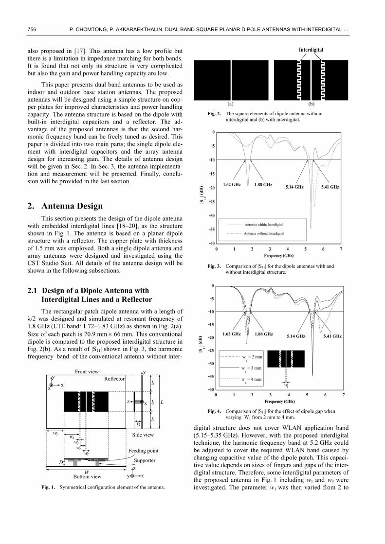
The rectangular patch dipole antenna with a length of λ/2 was designed and simulated at resonant frequency of 1.8 GHz (LTE band: 1.72–1.83 GHz) as shown in Fig. 2(a). Size of each patch is 70.9 mm 66 mm. This conventional dipole is compared to the proposed interdigital structure in Fig. 2(b). As a result of |S11| shown in Fig. 3, the harmonic frequency band of the conventional antenna without inter-
Fig. 1. Symmetrical configuration element of the antenna.
(a) (b)
Fig. 2. The square elements of dipole antenna without interdigital and (b) with interdigital.
Fig. 3. Comparison of |S11| for the dipole antennas with and
without interdigital structure.
Fig. 4. Comparison of |S11| for the effect of dipole gap when
varying W1 from 2 mm to 4 mm.
digital structure does not cover WLAN application band (5.15–5.35 GHz). However, with the proposed interdigital technique, the harmonic frequency band at 5.2 GHz could be adjusted to cover the required WLAN band caused by changing capacitive value of the dipole patch. This capaci-tive value depends on sizes of fingers and gaps of the inter-digital structure. Therefore, some interdigital parameters of the proposed antenna in Fig. 1 including w1 and w3 were investigated. The parameter w1 was then varied from 2 to
RADIOENGINEERING, VOL. 26, NO. 3, SEPTEMBER 2017 757
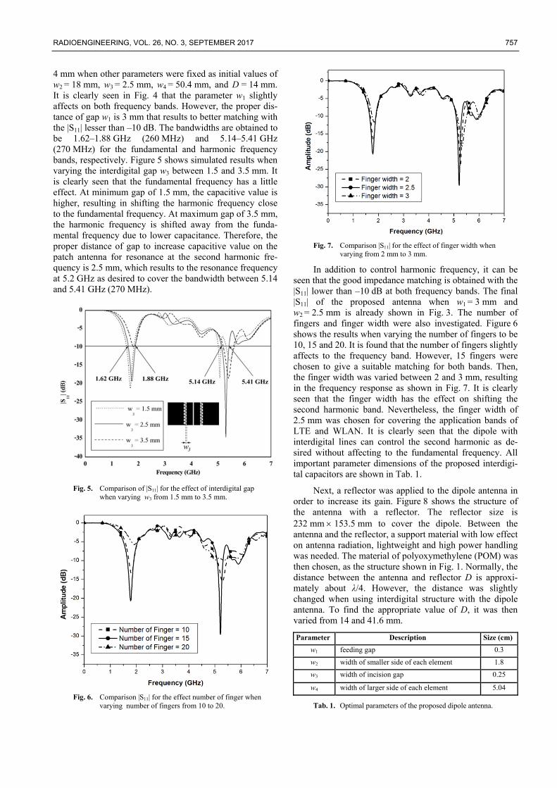
4 mm when other parameters were fixed as initial values of w2 = 18 mm, w3 = 2.5 mm, w4 = 50.4 mm, and D = 14 mm. It is clearly seen in Fig. 4 that the parameter w1 slightly affects on both frequency bands. However, the proper dis-tance of gap w1 is 3 mm that results to better matching with the |S11| lesser than –10 dB. The bandwidths are obtained to be 1.62–1.88 GHz (260 MHz) and 5.14–5.41 GHz (270 MHz) for the fundamental and harmonic frequency bands, respectively. Figure 5 shows simulated results when varying the interdigital gap w3 between 1.5 and 3.5 mm. It is clearly seen that the fundamental frequency has a little effect. At minimum gap of 1.5 mm, the capacitive value is higher, resulting in shifting the harmonic frequency close to the fundamental frequency. At maximum gap of 3.5 mm, the harmonic frequency is shifted away from the funda-mental frequency due to lower capacitance. Therefore, the proper distance of gap to increase capacitive value on the patch antenna for resonance at the second harmonic fre-quency is 2.5 mm, which results to the resonance frequency at 5.2 GHz as desired to cover the bandwidth between 5.14 and 5.41 GHz (270 MHz).
Fig. 5. Comparison of |S11| for the effect of interdigital gap
when varying w3 from 1.5 mm to 3.5 mm.
Fig. 6. Comparison |S11| for the effect number of finger when
varying number of fingers from 10 to 20.
Fig. 7. Comparison |S11| for the effect of finger width when
varying from 2 mm to 3 mm.
In addition to control harmonic frequency, it can be seen that the good impedance matching is obtained with the |S11| lower than –10 dB at both frequency bands. The final |S11| of the proposed antenna when w1 = 3 mm and w2 = 2.5 mm is already shown in Fig. 3. The number of fingers and finger width were also investigated. Figure 6 shows the results when varying the number of fingers to be 10, 15 and 20. It is found that the number of fingers slightly affects to the frequency band. However, 15 fingers were chosen to give a suitable matching for both bands. Then, the finger width was varied between 2 and 3 mm, resulting in the frequency response as shown in Fig. 7. It is clearly seen that the finger width has the effect on shifting the second harmonic band. Nevertheless, the finger width of 2.5 mm was chosen for covering the application bands of LTE and WLAN. It is clearly seen that the dipole with interdigital lines can control the second harmonic as de-sired without affecting to the fundamental frequency. All important parameter dimensions of the proposed interdigi-tal capacitors are shown in Tab. 1.
Next, a reflector was applied to the dipole antenna in order to increase its gain. Figure 8 shows the structure of the antenna with a reflector. The reflector size is 232 mm 153.5 mm to cover the dipole. Between the antenna and the reflector, a support material with low effect on antenna radiation, lightweight and high power handling was needed. The material of polyoxymethylene (POM) was then chosen, as the structure shown in Fig. 1. Normally, the distance between the antenna and reflector D is approxi-mately about λ/4. However, the distance was slightly changed when using interdigital structure with the dipole antenna. To find the appropriate value of D, it was then varied from 14 and 41.6 mm.
Parameter Description Size (cm)
w1 feeding gap 0.3
w2 width of smaller side of each element 1.8
w3 width of incision gap 0.25
w4 width of larger side of each element 5.04
Tab. 1. Optimal parameters of the proposed dipole antenna.
758 P. CHOMTONG, P. AKKARAEKTHALIN, DUAL BAND SQUARE PLANAR DIPOLE ANTENNAS WITH INTERDIGITAL …
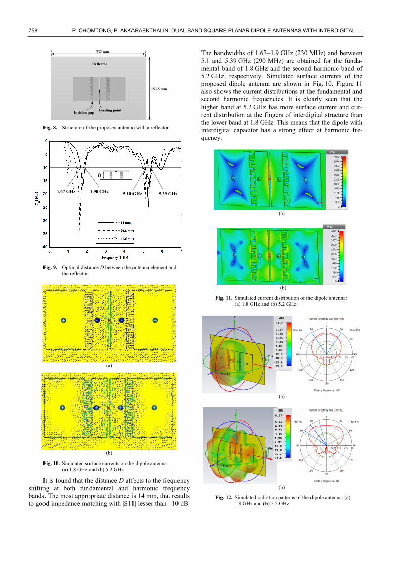
Fig. 8. Structure of the proposed antenna with a reflector.
1.67 GHz 1.90 GHz 5.10 GHz 5.39 GHz
D
Fig. 9. Optimal distance D between the antenna element and
the reflector.
(a)
(b)
Fig. 10. Simulated surface currents on the dipole antenna (a) 1.8 GHz and (b) 5.2 GHz.
It is found that the distance D affects to the frequency shifting at both fundamental and harmonic frequency bands. The most appropriate distance is 14 mm, that results to good impedance matching with |S11| lesser than –10 dB.
The bandwidths of 1.67–1.9 GHz (230 MHz) and between 5.1 and 5.39 GHz (290 MHz) are obtained for the funda-mental band of 1.8 GHz and the second harmonic band of 5.2 GHz, respectively. Simulated surface currents of the proposed dipole antenna are shown in Fig. 10. Figure 11 also shows the current distributions at the fundamental and second harmonic frequencies. It is clearly seen that the higher band at 5.2 GHz has more surface current and cur-rent distribution at the fingers of interdigital structure than the lower band at 1.8 GHz. This means that the dipole with interdigital capacitor has a strong effect at harmonic fre-quency.
(a)
(b)
Fig. 11. Simulated current distribution of the dipole antenna: (a) 1.8 GHz and (b) 5.2 GHz.
(a)
(b)
Fig. 12. Simulated radiation patterns of the dipole antenna: (a) 1.8 GHz and (b) 5.2 GHz.
RADIOENGINEERING, VOL. 26, NO. 3, SEPTEMBER 2017 759
Parameter Description Size(cm)L length of reflector 15.3 W width of reflector 21.5 D distance between array antenna and reflector 1.4 w1 feeding gap 0.3 w2 width of smaller side of each element 1.8 w3 width of incision gap 0.25 w4 width of larger side of each element 5.04 w5 distance from reflector to antenna element 3.56 l1 distance between of each antenna element 3.5 l2 length of each element 6.65 l3 distance from upper reflector to upper
antenna element 3.57
Tab. 2. Optimal parameters of the dipole antenna with the reflector.
Property 1.8 GHz 5.2 GHz Angular beamwidth (degree) 42.1 22.9 Main lobe direction (degree) 0 29 Back lobe (dB) –10.1 –23.29 Side lobe (dB) –20.8 –13.3 Gain (dBi) 10.71 8.37
Tab. 3. Radiation properties of the antenna with the reflector.
Figure 12 shows the simulated radiation patterns which are directional at both frequency bands. The simu-lated gain at 1.8 GHz is 10.7 dB at direction 0 degree and size of main lobe is 42.1 degree, while at 5.2 GHz the gain is 8.37 dB at the best direction of 22.9 degree. All key parameters of the dipole antenna with the reflector in Fig. 1 are shown in Tab. 2. Also the important characteristics of the antenna are included in Tab. 3. This antenna could be used for indoor applications.
2.2 Design of Array Antennas
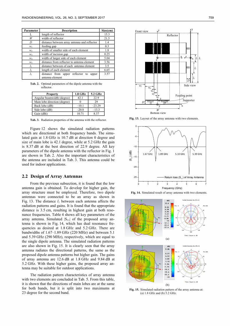
From the previous subsection, it is found that the low antenna gain is obtained. To develop for higher gain, the array structure must be employed. Therefore, two dipole antennas were connected to be an array as shown in Fig. 13. The distance l1 between each antenna affects the radiation patterns and gains. It is found that the appropriate distance is 3.5 cm, resulting in highest gain at both reso-nance frequencies. Table 4 shows all key parameters of the array antenna. Simulated |S11| of the proposed array an-tenna is shown in Fig. 14, which has dual resonance fre-quencies as desired at 1.8 GHz and 5.2 GHz. There are bandwidths of 1.67–1.89 GHz (220 MHz) and between 5.1 and 5.39 GHz (290 MHz), respectively, which are equal to the single dipole antenna. The simulated radiation patterns are also shown in Fig. 15. It is clearly seen that the array antenna radiates the directional patterns, the same as the proposed dipole antenna patterns but higher gain. The gains of array antenna are 12.6 dB at 1.8 GHz and 9.84 dB at 5.2 GHz. With these higher gains, the proposed array an-tenna may be suitable for outdoor applications.
The radiation pattern characteristics of array antenna with two elements are concluded in Tab. 5. From this table, it is shown that the directions of main lobes are at the same for both bands, but it is split into two maximums at 23 degree for the second band.
Front viewReflector
Side view
Bottom view
Feeding point
Supporter
y
xz
y
xz
D
L
W
Dy x
z
w5 w4
w3
w2
w1
l1
l2
l3
Fig. 13. Layout of the array antenna with two elements.
Fig. 14. Simulated result of array antenna with two elements.
(a)
(b)
Fig. 15. Simulated radiation pattern of the array antenna at: (a) 1.8 GHz and (b) 5.2 GHz.
760 P. CHOMTONG, P. AKKARAEKTHALIN, DUAL BAND SQUARE PLANAR DIPOLE ANTENNAS WITH INTERDIGITAL …
Parameter Description Size(cm)
L length of reflector 24.5
W width of reflector 21.5
D distance between array antenna and reflector
1.4
w1 feeding gap 0.3
w2 width of smaller side of each element 1.8 w3 width of incision gap 0.25 w4 width of larger side of each element 5.04
w5 distance from reflector to antenna element 3.56
l1 distance between of each antenna element 3.5
l2 length of each element 6.65
l3 distance from upper reflector to upper antenna element
3.57
Tab. 4. Parameters of the array antenna with two elements.
Property 1.8 GHz 5.2 GHz Angular beamwidth (degree) 48 33.25 Main lobe direction (degree) 0 23 Back lobe (dB) –13 –19 Side lobe (dB) –19.5 –12.3 Gain (dBi) 12.6 9.84
Tab. 5. Properties of radiation pattern for the array antenna with two elements.
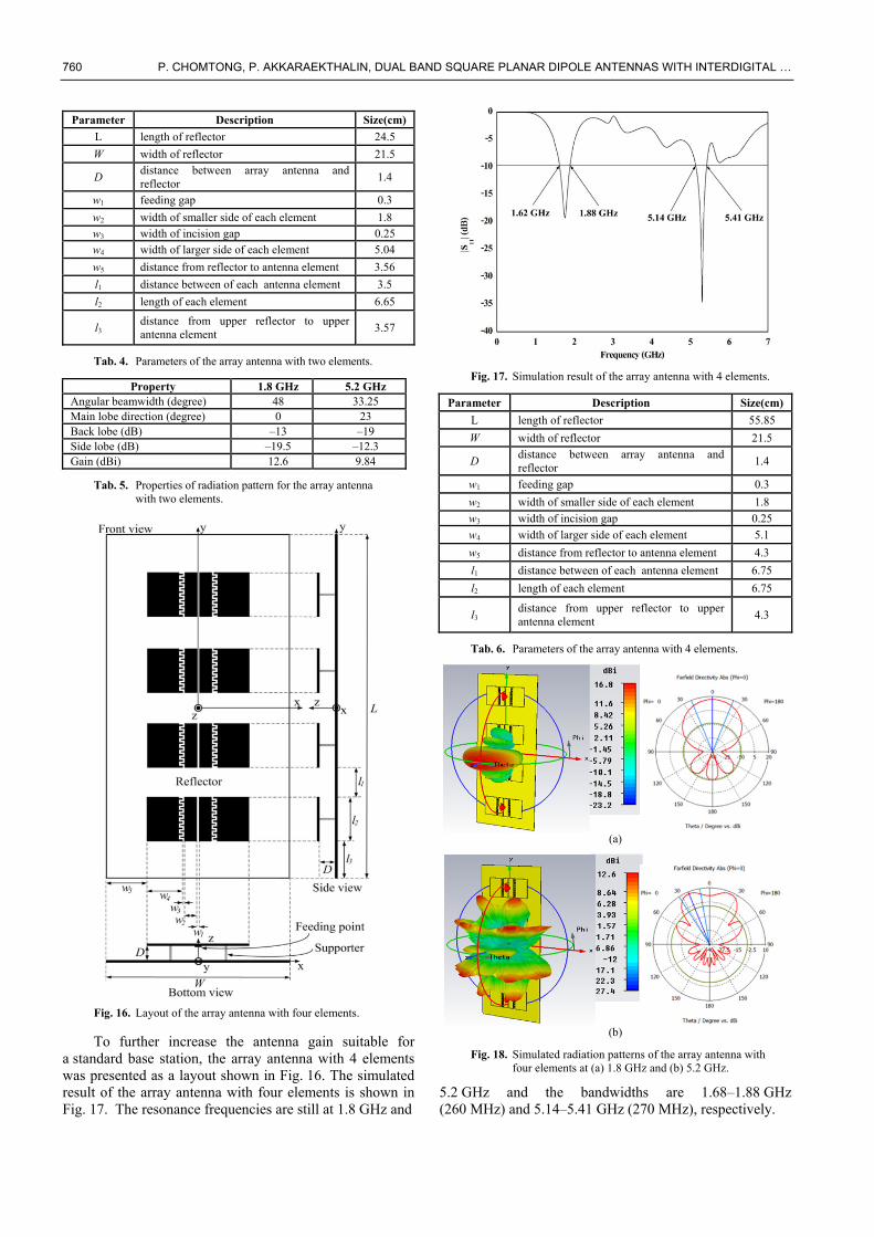
Fig. 16. Layout of the array antenna with four elements.
To further increase the antenna gain suitable for a standard base station, the array antenna with 4 elements was presented as a layout shown in Fig. 16. The simulated result of the array antenna with four elements is shown in Fig. 17. The resonance frequencies are still at 1.8 GHz and
Fig. 17. Simulation result of the array antenna with 4 elements.
Parameter Description Size(cm)
L length of reflector 55.85
W width of reflector 21.5
D distance between array antenna and reflector
1.4
w1 feeding gap 0.3
w2 width of smaller side of each element 1.8
w3 width of incision gap 0.25
w4 width of larger side of each element 5.1
w5 distance from reflector to antenna element 4.3
l1 distance between of each antenna element 6.75
l2 length of each element 6.75
l3 distance from upper reflector to upper antenna element
4.3
Tab. 6. Parameters of the array antenna with 4 elements.
(a)
(b)
Fig. 18. Simulated radiation patterns of the array antenna with four elements at (a) 1.8 GHz and (b) 5.2 GHz.
5.2 GHz and the bandwidths are 1.68–1.88 GHz (260 MHz) and 5.14–5.41 GHz (270 MHz), respectively.
RADIOENGINEERING, VOL. 26, NO. 3, SEPTEMBER 2017 761
Property 1.8 GHz 5.2 GHz Angular beamwidth (degree) 43.5 22.3 Main lobe direction (degree) 0 22 Back lobe (dB) –8.87 –20.25 Side lobe (dB) –25.7 –14.2 Gain (dBi) 16.84 12.6
Tab. 7. Properties of radiation pattern for the array antenna with four elements.
The simulated radiation patterns are also shown in Fig. 18. It is found that at 1.8 GHz, the antenna radiates directionally at 0 degree with gain of 16.8 dB as shown in Fig. 18(a). In Fig. 18(b), the main lobe is split into two maximums in the direction of 22 degree at 5.2 GHz with gain of 12.6 dB. The size of the proposed array antenna is 23.2 cm 55.8 cm. Table 6 concludes all key parameters of the antenna structure in Fig. 16. The properties of radiation pattern are also shown in Tab. 7. This proposed antenna can be potentially used for outdoor applications as a dual band base station antenna because of its good perfor-mances, especially high gain and high power handling capacity.
The proposed array antenna is smaller than the con-ventional base station antenna. Also, it is easy to design and control harmonic frequency or the second band fre-quency as needed. Next, antenna fabrication and measure-ment results will be presented.
3. Implementation and Results After designing the proposed antenna as mentioned in
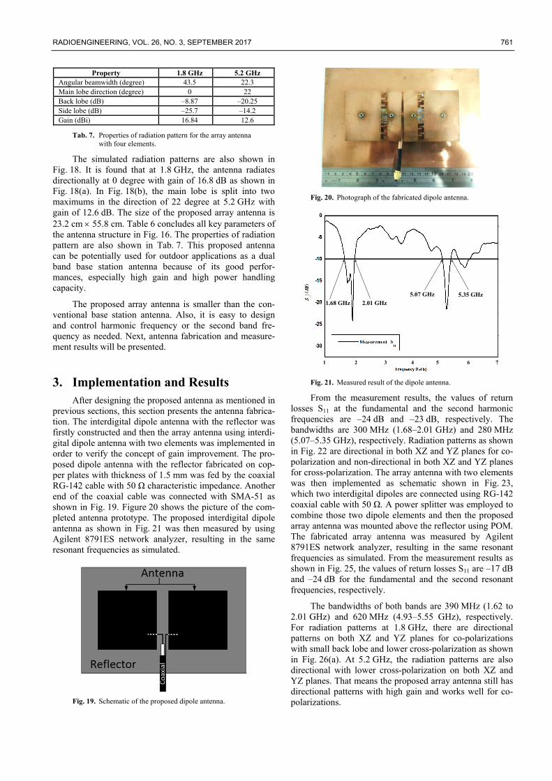
previous sections, this section presents the antenna fabrica-tion. The interdigital dipole antenna with the reflector was firstly constructed and then the array antenna using interdi-gital dipole antenna with two elements was implemented in order to verify the concept of gain improvement. The pro-posed dipole antenna with the reflector fabricated on cop-per plates with thickness of 1.5 mm was fed by the coaxial RG-142 cable with 50 Ω characteristic impedance. Another end of the coaxial cable was connected with SMA-51 as shown in Fig. 19. Figure 20 shows the picture of the com-pleted antenna prototype. The proposed interdigital dipole antenna as shown in Fig. 21 was then measured by using Agilent 8791ES network analyzer, resulting in the same resonant frequencies as simulated.
Fig. 19. Schematic of the proposed dipole antenna.
Fig. 20. Photograph of the fabricated dipole antenna.
1.68 GHz 2.01 GHz
5.07 GHz 5.35 GHz
1 2 4 63 5 7
Fig. 21. Measured result of the dipole antenna.
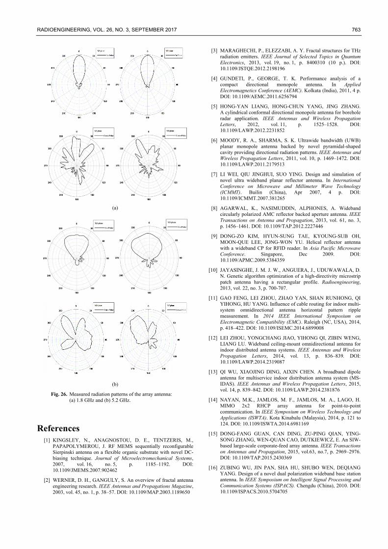
From the measurement results, the values of return losses S11 at the fundamental and the second harmonic frequencies are –24 dB and –23 dB, respectively. The bandwidths are 300 MHz (1.68–2.01 GHz) and 280 MHz (5.07–5.35 GHz), respectively. Radiation patterns as shown in Fig. 22 are directional in both XZ and YZ planes for co-polarization and non-directional in both XZ and YZ planes for cross-polarization. The array antenna with two elements was then implemented as schematic shown in Fig. 23, which two interdigital dipoles are connected using RG-142 coaxial cable with 50 Ω. A power splitter was employed to combine those two dipole elements and then the proposed array antenna was mounted above the reflector using POM. The fabricated array antenna was measured by Agilent 8791ES network analyzer, resulting in the same resonant frequencies as simulated. From the measurement results as shown in Fig. 25, the values of return losses S11 are –17 dB and –24 dB for the fundamental and the second resonant frequencies, respectively.
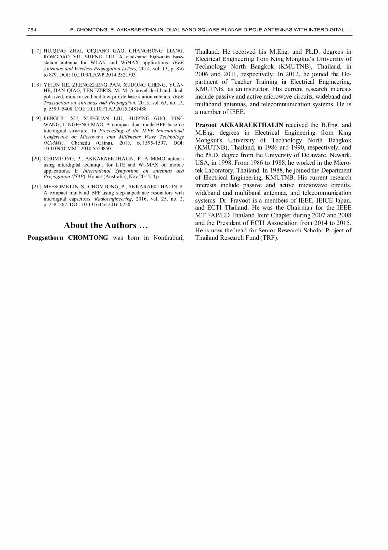
The bandwidths of both bands are 390 MHz (1.62 to 2.01 GHz) and 620 MHz (4.93–5.55 GHz), respectively. For radiation patterns at 1.8 GHz, there are directional patterns on both XZ and YZ planes for co-polarizations with small back lobe and lower cross-polarization as shown in Fig. 26(a). At 5.2 GHz, the radiation patterns are also directional with lower cross-polarization on both XZ and YZ planes. That means the proposed array antenna still has directional patterns with high gain and works well for co-polarizations.
762 P. CHOMTONG, P. AKKARAEKTHALIN, DUAL BAND SQUARE PLANAR DIPOLE ANTENNAS WITH INTERDIGITAL …
(a)
(b)
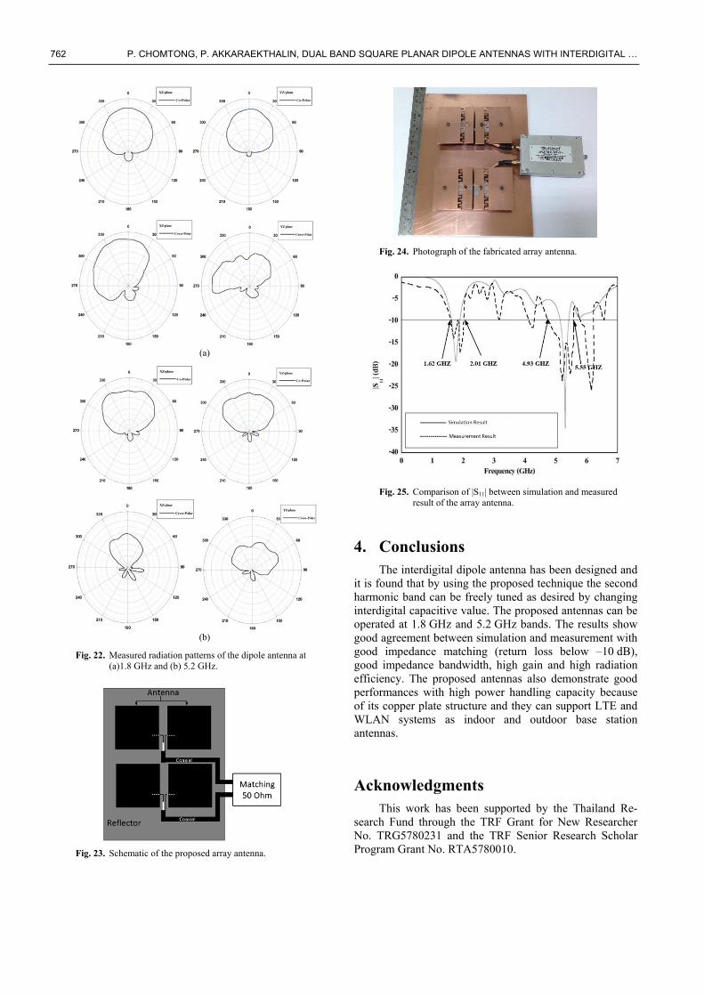
Fig. 22. Measured radiation patterns of the dipole antenna at (a)1.8 GHz and (b) 5.2 GHz.
Fig. 23. Schematic of the proposed array antenna.
Fig. 24. Photograph of the fabricated array antenna.
Fig. 25. Comparison of |S11| between simulation and measured
result of the array antenna.
4. Conclusions The interdigital dipole antenna has been designed and
it is found that by using the proposed technique the second harmonic band can be freely tuned as desired by changing interdigital capacitive value. The proposed antennas can be operated at 1.8 GHz and 5.2 GHz bands. The results show good agreement between simulation and measurement with good impedance matching (return loss below –10 dB), good impedance bandwidth, high gain and high radiation efficiency. The proposed antennas also demonstrate good performances with high power handling capacity because of its copper plate structure and they can support LTE and WLAN systems as indoor and outdoor base station antennas.
Acknowledgments This work has been supported by the Thailand Re-
search Fund through the TRF Grant for New Researcher No. TRG5780231 and the TRF Senior Research Scholar Program Grant No. RTA5780010.
RADIOENGINEERING, VOL. 26, NO. 3, SEPTEMBER 2017 763
(a)
(b)
Fig. 26. Measured radiation patterns of the array antenna: (a) 1.8 GHz and (b) 5.2 GHz.
References [1] KINGSLEY, N., ANAGNOSTOU, D. E., TENTZERIS, M.,
PAPAPOLYMEROU, J. RF MEMS sequentially reconfigurable Sierpinski antenna on a flexible organic substrate with novel DC-biasing technique. Journal of Microelectromechanical Systems, 2007, vol. 16, no. 5, p. 1185–1192. DOI: 10.1109/JMEMS.2007.902462
[2] WERNER, D. H., GANGULY, S. An overview of fractal antenna engineering research. IEEE Antennas and Propagations Magazine, 2003, vol. 45, no. 1, p. 38–57. DOI: 10.1109/MAP.2003.1189650
[3] MARAGHECHI, P., ELEZZABI, A. Y. Fractal structures for THz radiation emitters. IEEE Journal of Selected Topics in Quantum Electronics, 2013, vol. 19, no. 1, p. 8400310 (10 p.). DOI: 10.1109/JSTQE.2012.2198196
[4] GUNDETI, P., GEORGE, T. K. Performance analysis of a compact directional monopole antenna. In Applied Electromagnetics Conference (AEMC). Kolkata (India), 2011, 4 p. DOI: 10.1109/AEMC.2011.6256794
[5] HONG-YAN LIANG, HONG-CHUN YANG, JING ZHANG. A cylindrical conformal directional monopole antenna for borehole radar application. IEEE Antennas and Wireless Propagation Letters, 2012, vol. 11, p. 1525–1528. DOI: 10.1109/LAWP.2012.2231852
[6] MOODY, R. A., SHARMA, S. K. Ultrawide bandwidth (UWB) planar monopole antenna backed by novel pyramidal-shaped cavity providing directional radiation patterns. IEEE Antennas and Wireless Propagation Letters, 2011, vol. 10, p. 1469–1472. DOI: 10.1109/LAWP.2011.2179513
[7] LI WEI, QIU JINGHUI, SUO YING. Design and simulation of novel ultra wideband planar reflector antenna. In International Conference on Microwave and Millimeter Wave Technology (ICMMT). Builin (China), Apr 2007, 4 p. DOI: 10.1109/ICMMT.2007.381265
[8] AGARWAL, K., NASIMUDDIN, ALPHONES, A. Wideband circularly polarized AMC reflector backed aperture antenna. IEEE Transactions on Antenna and Propagation, 2013, vol. 61, no. 3, p. 1456–1461. DOI: 10.1109/TAP.2012.2227446
[9] DONG-ZO KIM, HYUN-SUNG TAE, KYOUNG-SUB OH, MOON-QUE LEE, JONG-WON YU. Helical reflector antenna with a wideband CP for RFID reader. In Asia Pacific Microwave Conference. Singapore, Dec 2009. DOI: 10.1109/APMC.2009.5384359
[10] JAYASINGHE, J. M. J. W., ANGUERA, J., UDUWAWALA, D. N. Genetic algorithm optimization of a high-directivity microstrip patch antenna having a rectangular profile. Radioengineering, 2013, vol. 22, no. 3, p. 700-707.
[11] GAO FENG, LEI ZHOU, ZHAO YAN, SHAN RUNHONG, QI YIHONG, HU YANG. Influence of cable routing for indoor multi-system omnidirectional antenna horizontal pattern ripple measurement. In 2014 IEEE International Symposium on Electromagnetic Compatibility (EMC). Raleigh (NC, USA), 2014, p. 418–422. DOI: 10.1109/ISEMC.2014.6899008
[12] LEI ZHOU, YONGCHANG JIAO, YIHONG QI, ZIBIN WENG, LIANG LU. Wideband ceiling-mount omnidirectional antenna for indoor distributed antenna systems. IEEE Antennas and Wireless Propagation Letters, 2014, vol. 13, p. 836–839. DOI: 10.1109/LAWP.2014.2319087
[13] QI WU, XIAOJING DING, AIXIN CHEN. A broadband dipole antenna for multiservice indoor distribution antenna system (MS-IDAS). IEEE Antennas and Wireless Propagation Letters, 2015, vol. 14, p. 839–842. DOI: 10.1109/LAWP.2014.2381876
[14] NAYAN, M.K., JAMLOS, M. F., JAMLOS, M. A., LAGO, H. MIMO 2x2 RHCP array antenna for point-to-point communication. In IEEE Symposium on Wireless Technology and Applications (ISWTA). Kota Kinabalu (Malaysia), 2014, p. 121 to 124. DOI: 10.1109/ISWTA.2014.6981169
[15] DONG-FANG GUAN, CAN DING, ZU-PING QIAN, YING-SONG ZHANG, WEN-QUAN CAO, DUTKIEWICZ, E. An SIW-based large-scale corporate-feed array antenna. IEEE Transactions on Antennas and Propagation, 2015, vol.63, no.7, p. 2969–2976. DOI: 10.1109/TAP.2015.2430369
[16] ZUBING WU, JIN PAN, SHA HU, SHUBO WEN, DEQIANG YANG. Design of a novel dual polarization wideband base station antenna. In IEEE Symposium on Intelligent Signal Processing and Communication Systems (ISPACS). Chengdu (China), 2010. DOI: 10.1109/ISPACS.2010.5704705
764 P. CHOMTONG, P. AKKARAEKTHALIN, DUAL BAND SQUARE PLANAR DIPOLE ANTENNAS WITH INTERDIGITAL …
[17] HUIQING ZHAI, QIQIANG GAO, CHANGHONG LIANG, RONGDAO YU, SHENG LIU. A dual-band high-gain base-station antenna for WLAN and WiMAX applications. IEEE Antennas and Wireless Propagation Letters, 2014, vol. 13, p. 876 to 879. DOI: 10.1109/LAWP.2014.2321503
[18] YEJUN HE, ZHENGZHENG PAN, XUDONG CHENG, YUAN HE, JIAN QIAO, TENTZERIS, M. M. A novel dual-band, dual-polarized, miniaturized and low-profile base station antenna. IEEE Transaction on Antennas and Propagation, 2015, vol. 63, no. 12, p. 5399–5408. DOI: 10.1109/TAP.2015.2481488
[19] FENGLIU XU, XUEGUAN LIU, HUIPING GUO, YING WANG, LINGFENG MAO. A compact dual mode BPF base on interdigital structure. In Proceeding of the IEEE International Conference on Microwave and Millimeter Wave Technology (ICMMT). Chengdu (China), 2010, p. 1595–1597. DOI: 10.1109/ICMMT.2010.5524850
[20] CHOMTONG, P., AKKARAEKTHALIN, P. A MIMO antenna using interdigital technique for LTE and Wi-MAX on mobile applications. In International Symposium on Antennas and Propagation (ISAP). Hobart (Australia), Nov 2015, 4 p.
[21] MEESOMKLIN, S., CHOMTONG, P., AKKARAEKTHALIN, P. A compact mutiband BPF using step-impedance resonators with interdigital capacitors. Radioengineering, 2016, vol. 25, no. 2, p. 258–267. DOI: 10.13164/re.2016.0258
About the Authors … Pongsathorn CHOMTONG was born in Nonthaburi,
Thailand. He received his M.Eng. and Ph.D. degrees in Electrical Engineering from King Mongkut’s University of Technology North Bangkok (KMUTNB), Thailand, in 2006 and 2011, respectively. In 2012, he joined the De-partment of Teacher Training in Electrical Engineering, KMUTNB, as an instructor. His current research interests include passive and active microwave circuits, wideband and multiband antennas, and telecommunication systems. He is a member of IEEE.
Prayoot AKKARAEKTHALIN received the B.Eng. and M.Eng. degrees in Electrical Engineering from King Mongkut's University of Technology North Bangkok (KMUTNB), Thailand, in 1986 and 1990, respectively, and the Ph.D. degree from the University of Delaware, Newark, USA, in 1998. From 1986 to 1988, he worked in the Micro-tek Laboratory, Thailand. In 1988, he joined the Department of Electrical Engineering, KMUTNB. His current research interests include passive and active microwave circuits, wideband and multiband antennas, and telecommunication systems. Dr. Prayoot is a members of IEEE, IEICE Japan, and ECTI Thailand. He was the Chairman for the IEEE MTT/AP/ED Thailand Joint Chapter during 2007 and 2008 and the President of ECTI Association from 2014 to 2015. He is now the head for Senior Research Scholar Project of Thailand Research Fund (TRF).