Predicting Human Movement based on Telecom's Handoff in Mobile ...

DTX-360
DIGITAL CIRCUITMULTIPLICATION EQUIPMENT
GENERAL DESCRIPTION
Copyright © ECI Telecom 1997. All Rights Reserved.
This manual may contain minor flaws, omissions or typesetting errors. Information contained herein isperiodically updated and changes will be incorporated into subsequent editions. If you have encountered anerror, please notify ECI Telecom. All specifications are subject to change without prior notice.

CE Mark Compliance Sheet
The DTX-360 is marked with a CE Mark (see below). This mark has beenaffixed to demonstrate full product compliance with the following Europeandirectives:
a) Directive 73/23/EEC - Council Directive of 19/02/1973 on theharmonization of the laws of Member States relating to electrical equipmentdesigned for use within certain voltage limits.
b) Directive 89/336/EEC - Council Directive of 3/05/1989 on theapproximation of laws of the Member States relating to Electro-MagneticCompatibility (EMC).
Issue Date: February 6, 1996

92050001-07 i
DTX-360
General Description
Table of ContentsSection Description Page
CE Mark Compliance Sheet................................................................................................... A
1 INTRODUCTION................................................................................................................. 1-1
1.1 General................................................................................................................................ 1-1
1.2 Main Features ..................................................................................................................... 1-2
2 BASIC DESIGN................................................................................................................... 2-1
2.1 Functional Blocks ................................................................................................................ 2-1
2.2 TR-DLI - Trunk Digital Line Interface .................................................................................. 2-1
2.3 TSI&SA - Time Slot Interchange & Signal Analysis ............................................................ 2-1
2.3.1 TSI - Time Slot Interchange ................................................................................................ 2-1
2.3.2 Signal Analysis .................................................................................................................... 2-3
2.4 DSI - Digital Speech Interpolation ....................................................................................... 2-3
2.5 S-LRE - Speech Low Rate Encoding .................................................................................. 2-3
2.5.1 LD-CELP Low Delay Code Excited Linear Prediction ......................................................... 2-3
2.5.2 ADPCM - Adaptive Differential PCM................................................................................... 2-3
2.6 VBR - Variable Bit Rate....................................................................................................... 2-3
2.6.1 VBR and LD-CELP.............................................................................................................. 2-3
2.6.2 VBR and ADPCM................................................................................................................ 2-3
2.7 VBD-LRE - Voice Band Data - Low Rate Encoding ............................................................ 2-3
2.8 FAX - Group 3 Facsimile..................................................................................................... 2-4
2.8.1 FAX Process (Demodulation-Modulation)........................................................................... 2-4
2.9 BM - Bit Mapping................................................................................................................. 2-4
2.10 BR-DLI - Bearer Digital Line Interface (PCM) ..................................................................... 2-4
3 TRAFFIC HANDLING FEATURES ..................................................................................... 3-1
3.1 Performance........................................................................................................................ 3-1
3.2 Bearer Assignment.............................................................................................................. 3-2
3.2.1 Dynamic Assignment .......................................................................................................... 3-2
3.2.2 Pre-Assignment................................................................................................................... 3-2
3.2.3 Inter-Exchange Signaling .................................................................................................... 3-2

ii 92050001-07
Table of Contents (continued)
Section Description Page
3.3 Network Operating Modes ...................................................................................................3-3
3.3.1 Multi-Clique (MC) Mode .......................................................................................................3-3
3.3.2 Multi-Destination (MD) Mode ...............................................................................................3-3
3.3.3 Interoperation.......................................................................................................................3-3
3.4 Traffic Overload Handling ....................................................................................................3-3
4 CLUSTER CONFIGURATION.............................................................................................4-1
4.1 General ................................................................................................................................4-1
4.2 DCOM - Distributed Change Over Matrix ............................................................................4-3
4.2.1 LCOM - Local Change Over Matrix .....................................................................................4-3
4.2.2 CCOM - Central Change Over Matrix..................................................................................4-3
4.2.3 Micro-Cluster COM ..............................................................................................................4-3
4.3 DTX-360 OPS......................................................................................................................4-5
5 PHYSICAL DESCRIPTION..................................................................................................5-1
5.1 Dimensions ..........................................................................................................................5-1
5.2 Card Shelf Description.........................................................................................................5-1
5.2.1 DTX-360 Terminal ...............................................................................................................5-1
5.2.2 Change-Over Matrix (COM).................................................................................................5-2
5.3 Power Supply .......................................................................................................................5-2
6 TERMINAL CARDS FUNCTIONAL DESCRIPTION ..........................................................6-1
6.1 Functional Subsystems........................................................................................................6-1
6.2 Interface Subsystems ..........................................................................................................6-1
6.2.1 RDSW - Redundancy Switch...............................................................................................6-1
6.2.2 QDLI - Quad Digital Line Interface.......................................................................................6-1
6.2.3 TSDF - Time Slot Interchange and DCME Frame Alignment..............................................6-2
6.2.4 CKSL - Clock Select Card ...................................................................................................6-3
6.3 Transmit Subsystem............................................................................................................6-3
6.3.1 DSIT - Digital Speech Interpolation - Transmit ....................................................................6-3
6.3.2 SDSP - Signal Analysis DSP SCPU - Signal Analysis CPU ...............................................6-3
6.3.3 TCPU - Transmit CPU .........................................................................................................6-4
6.3.4 LDCT - Low Delay-Code Excited Linear Predictor - Encoder ..............................................6-4
6.3.5 ADPC - Adaptive Differential PCM - Encoder ......................................................................6-4
6.3.6 TDSP - Transmit Demodulator (FAX)..................................................................................6-4
6.3.7 BMCT - Bit Map CPU - Transmit .........................................................................................6-5
6.4 Receive Subsystem .............................................................................................................6-5
6.4.1 BMCR - Bearer Map CPU - Receive....................................................................................6-5
6.4.2 DSIR - Digital Speech Interpolation - Receive .....................................................................6-6
6.4.3 ADPX - Adaptive Differential PCM - Decoder......................................................................6-6
6.4.4 LDCR - Low Delay-Code Excited Linear Prediction - Decoder...........................................6-6

92050001-07 iii
Table of Contents (continued)
Section Description Page
6.4.5 RDSP - Fax ReModulator ................................................................................................... 6-6
6.4.6 RCPU - Receive CPU ......................................................................................................... 6-7
6.5 OMCP - Operation & Maintenance CPU............................................................................. 6-7
6.6 SIGN - Signaling CPU......................................................................................................... 6-7
7 SYNCHRONIZATION ......................................................................................................... 7-1
7.1 Synchronization Modes ....................................................................................................... 7-1
7.2 Plesiochronous Operation................................................................................................... 7-1
7.3 Wander and Jitter................................................................................................................ 7-1
7.4 Slips..................................................................................................................................... 7-1
7.5 Clocking .............................................................................................................................. 7-2
8 MAINTENANCE FACILITIES.............................................................................................. 8-1
8.1 Functions............................................................................................................................. 8-1
8.2 Built-In-Test......................................................................................................................... 8-2
8.3 Terminal Alarms.................................................................................................................. 8-2
8.4 DTX-360 Display Panel (AUX Card Panel) ......................................................................... 8-2
8.4.1 Terminal Alarm Indications.................................................................................................. 8-2
8.4.2 Alphanumeric Display.......................................................................................................... 8-2
8.4.3 Order Wire Call Indicators................................................................................................... 8-2
8.4.4 Order Wire Buzzer .............................................................................................................. 8-2
8.4.5 Handset ............................................................................................................................... 8-2
8.4.6 Test Port (Drop & Insert) ..................................................................................................... 8-2
8.4.7 Power On/Off Switch........................................................................................................... 8-2
8.5 System Reset ...................................................................................................................... 8-2
9 TECHNICAL SPECIFICATIONS......................................................................................... 9-1
9.1 General................................................................................................................................ 9-1
10 GLOSSARY OF TERMS................................................................................................... 10-1

iv 92050001-07
List of FiguresFigure Description Page
Figure 1-1. DTX-360 Terminal ...............................................................................................................1-1
Figure 1-2. Network Components of a DTX-360 DCME System ...........................................................1-4
Figure 1-3. DTX-360 Point-to-Point Mode..............................................................................................1-5
Figure 1-4. DTX-360 Multi-Destination Mode.........................................................................................1-6
Figure 1-5. DTX-360 Multi-Clique Mode - 2 Cliques out of 4 Possible (in LD-CELP) ............................1-7
Figure 2-1. DTX-360 Terminal Functional Block Diagram .....................................................................2-2
Figure 3-1. DTX-360 Traffic Capacity - FEC Disabled ...........................................................................3-5
Figure 3-2. DTX-360 Traffic Capacity - FEC Enabled............................................................................3-6
Figure 4-1. DTX-360 Mixed Cluster Layout............................................................................................4-2
Figure 4-2. DCOM - Block Diagram .......................................................................................................4-4
Figure 5-1. DTX-360 Cabinet Assembly ................................................................................................5-3
Figure 5-2. Typical DTX-360 Cluster Configuration - Upper Cabling Installation...................................5-4
Figure 5-3. Typical DTX-360 Cluster Configuration - Lower Cabling Installation...................................5-5
Figure 5-4. DTX-360 With LD-CELP Option - Card Slot Designation ....................................................5-6
Figure 5-5. DTX-360 - ITU G.763 & G.766 Configuration Card Slot Designation..................................5-7
Figure 5-6. DTX-360C - Card Slot Designation......................................................................................5-8
Figure 5-7. Central COM - Card Slot Designation..................................................................................5-9
Figure 5-8. Local COM - Card Slot Designation...................................................................................5-10
Figure 7-1. DTX-360 Synchronization Modes ........................................................................................7-3
Figure 7-2. DTX-360 - System Clocks ...................................................................................................7-4
Figure 8-1. DTX-360 AUX Card .............................................................................................................8-3
List of TablesTable Description Page
Table 3-1 Signal Processing Alternatives ............................................................................................3-2
Table 3-2. DCME Multiple Destination Capability for Multi-Clique and Multi-Destination Modes..........3-3
Table 5-1. DTX-360 Cards - TX Shelf...................................................................................................5-1
Table 5-2. DTX-360 Cards - IF/RX Shelf ..............................................................................................5-2
Table 5-3. DTX-360 COM Cards ..........................................................................................................5-2

Figure 1-1. DTX-360 Terminal

92050001-07 1-1
1
INTRODUCTION
1.1 General
The DTX-360 Digital Circuit MultiplicationEquipment is the latest addition to ECITelecom's family of telecommunication products.
The DTX-360 is designed to provide globalsolutions to present and future DCMErequirements.
Figure 1-1 shows a DTX-360 terminal.
Utilizing DSI (Digital Speech Interpolation),ADPCM (Adaptive Differential PCM) orLD-CELP (Low Delay - Code Excited LinearPrediction), VBR (Variable Bit Rate), and FaxDemodulation/Modulation techniques, theDTX-360 enables a maximum effectivecompression of transmission facilities in digitaloperating environments, together with a veryhigh level of signal quality and system reliability.
Each DTX-360 terminal accepts up to 360 trunkchannels, carrying 64 kbit/s signals of speech,voice-band data (fax and non-fax), andinter-exchange signaling types. These signalsare transmitted to their destination terminal(s)over a single bitstream (Bearer) at a rate of2.048 Mbit/s or 1.544 Mbit/s.
The DTX-360 system provides a highcompression ratio of up to 10:1 for speechsignals and a fax compression ratio of more than6:1 for ITU Group 3 fax calls.
Figure 1-2 shows the network components of aDTX-360 DCME.
In addition, the DTX-360 supports the followingnetwork operating modes:
Point-to-Point
Multi-Destination
Multi-Clique
Inter-operation
Figure 1-3, Figure 1-4, and Figure 1-5 illustratethe Point-to-Point, Multi-Destination, andMulti-Clique modes, respectively.
Note: Multi-Clique mode enables use of up to 4cliques.
The DTX-360 can be operated in one of thefollowing DCME modes:
LD-CELP mode
ITU G.763-G.766 mode. (Intelsat IESS-501,REV.3)
ITU G.763 mode (Intelsat IESS-501, REV.2)
The Fax Demodulation technique improvestransmission performance of fax calls bysignificantly reducing link impairments.
In addition, it is possible to apply error protectiontechniques to the fax demodulated signals. Thisresults in substantial improvements in the overallbit error rate performance for faxcommunications - an important feature whenoperating on links with poor bit error rateperformance.

Section 1 DTX-360Introduction General Description
1-2 92050001-07
A complete set of system configuration modesequips the DTX-360 with powerful operationalcharacteristics that assure top performance inalmost any environment.
The system supports various transmittedservices, including Nx64 kbit/s service andnon-interpolated traffic.
The DTX-360 provides an optional DCME-ISCdata communication link, using T.S. 16 of thetrunk bit streams, in full compliance with ITURec. Q.50. This data link enables informationexchange between the DTX-360 and associatedswitching nodes, for various ISDN bearerservices involving 64 kbit/s unrestricted traffic,DLC (Dynamic Load Control), alarms, and otherpurposes. In addition, the system will supportany user-customized protocol.
ECI Telecom has also developed the DTX-360C- a compact version of the DTX-360. TheDTX-360C is a single-shelf, optimized system,especially suited for IESS-501 applications.
1.2 Main Features
The DTX-360 offers the following main features:
Standard E1 (2.048 Mbit/s) and T1 (1.544Mbit/s) for Trunk and Bearer Interfaces
Compression ratio of up to 10:1 for speechsignals
Easy upgrading from G.763 version(ADPCM) to LD-CELP version (10:1 gain) byinsertion of plug-and-play LD-CELP andrelated cards and replacing terminal software(No modifications of shelf hardware arerequired)
Compression ratio of more than 6:1 for ITUGroup 3 fax calls
Compression ratio of 3:1 for half duplexnon-fax Voice Band Data calls of up to andincluding 19.2 kbit/s (1.6:1 for full duplex),using a unique LD-CELP-based algorithm
Transmission of 64 kbit/s dynamicallyassigned Clear Channels
Transmission of pre-assigned channels at 64kbit/s, 40 kbit/s, 32 kbit/s, and 16 kbit/s
Low Rate Encoding, using ADPCM orLD-CELP techniques
Transmission of up to 360 voice trunksduring distributed peak traffic hours
Transmission of more than 300 voice trunksduring non-distributed peak traffic hours
ITU Group 3 fax calls are demodulated bymeans of Waveform Analysis technique (ITUG.766)
Supports ITU Group 3 V.17, V.27, and V.29fax calls
Support for standard and non-standardprotocols (ITU T.30)
Simultaneous transmission of up to 180 ITUGroup 3 fax calls
Efficient Inter-Exchange Signaling support
Support for ITU Signaling Systems #5, #6,#7, R1 and R2D
DTX-360 - ISC data link interface incompliance with ITU Rec. Q.50
Optional DTX-360-ISC customized interfaces
Plesiochronous buffering and optionalDoppler buffer
Multi-Destination Mode with up to fourdestinations
Multi-Clique Mode with up to four pools(LD-CELP) and up to two pools (ADPCM)
Inter-operability of Single-Destination andMulti-Clique versus Multi-Destination
High level of noise immunity, even for high biterror rate bearers
Excellent speech call quality
Adaptive Threshold Setting and AdaptiveNoise Injection - enhancing speech quality ontrunk circuits with a high noise level
Forward Error Correction - enhancing fax callquality when operating on bearers withdegraded BER (Bit Error Rate)
High single-terminal and overall systemreliability
High level of system protection provided by acomprehensive Built-In-Test feature
Redundant traffic-affecting subsystems,ensuring Service Continuity Protection
Up to 8+1 terminals (8 operational and1 backup) in cluster configuration

DTX-360 Section 1General Description Introduction
92050001-07 1-3
Cluster configuration with distributedChange-Over Matrix
Reliable change-over process, independentof the Operator Station (OPS-360)
Fast restoration of service following an alarmcondition requiring change-over switching
Reduced cluster installation cost andimproved maintainability
High level of modularity that assuresimmediate system expansion in response tochanges in traffic profile and volume
Powerful Operator Station (OPS-360)incorporating advanced user interfacetechnologies
Attractive graphic user interface for theOperator Station (OPS-360)
Concurrent operation, maintenance. andcommissioning of multiple terminals,supported by a single Operator Station(OPS-360)
Safe and easy data entry through theOPS-360
Comprehensive system control and trafficmonitoring reports

Section 1 DTX-360Introduction General Description
1-4 92050001-07
Figure 1-2. Network Components of a DTX-360 DCME System

DTX-360 Section 1General Description Introduction
92050001-07 1-5
DT
X-3
60
Tx(
a)
Rx(
a)
Rx(
b)
Site
a
Site
b
Tx
( )
= T
rans
mit
Sid
eR
x (
) =
Rec
eive
S
ide
DT
X-3
60
Tx(
b)
Figure 1-3. DTX-360 Point-to-Point Mode

Section 1 DTX-360Introduction General Description
1-6 92050001-07
Ear
thS
tatio
nE
quip
men
t
Site
A
Nab Nba
Nac
Nca
DT
X36
0
to /
fro
mIS
C -
a
Site
a
Ear
thS
tatio
nE
quip
men
t
Site
B
Nba Nab
Nbc
Ncb
DT
X36
0
to /
fro
mIS
C -
b
Site
b
Ear
thS
tatio
nE
quip
men
t
Site
C
Nca
Nac
Ncb
Nbc
DT
X36
0
to /
fro
mIS
C -
c
Site
c
a
b
a
c
a
b,c
b
a
b
c
b
a,c
a
c
b
c
b,a
c
Figure 1-4. DTX-360 Multi-Destination Mode

DTX-360 Section 1General Description Introduction
92050001-07 1-7
Nab
Nba
Nac Nca
DT
X36
0
Nba Nab
Nbc Ncb
DT
X36
0
Nca
Nac
Ncb
Nbc
DT
X36
0
a
b
a
c
a
b
a
c
b
a
b
c
b
a
b
c
a
c
b
c
a
c
b
c
Ear
thS
tatio
nE
quip
men
t
Site
A
to /
fro
mIS
C -
a
Sit
e a
Ear
thS
tatio
nE
quip
men
t
Site
B
to /
fro
mIS
C -
b
Sit
e b
Ear
thS
tatio
nE
quip
men
t
Site
C
to /
fro
mIS
C -
c
Sit
e c
Figure 1-5. DTX-360 Multi-Clique Mode - 2 Cliques out of 4 Possible (in LD-CELP)

92050001-07 2-1
2
BASIC DESIGN
2.1 Functional Blocks
A DTX-360 system is implemented with severalinterconnected DTX-360 terminals. The type ofinterconnection and number of terminalsdepends on the network operational selectedmode (Point-to-Point, Multi-Clique orMulti-Destination).
A basic functional diagram of a DTX-360terminal is shown in Figure 2-1. The diagramillustrates different signal compressionprocedures in the transmit direction (from trunkchannels to bearer), corresponding to thepossible results of the incoming signal analysisprocess.
The same diagram also serves to illustratesignal processing in the receive direction. In thiscase, the signal flow is in the opposite directionand decompression procedures are applied.
There are ten basic functional stages:
TR-DLI - Trunk Digital Line Interface
TSI&SA - Timeslot Interchange & SignalAnalysis
DSI - Digital Speech Interpolation
S-LRE - Speech Low Rate Encoding /Decoding
VBR - Variable Bit Rate
VBD-LRE - Voice Band Data-Low RateEncoding/Decoding
FAX - DEM/MOD - Fax Demodulation /Remodulation
BM - Bit Mapping
FEC - Forward Error Correction
BR-DLI - Bearer Digital Line Interface
These stages are described briefly below.
2.2 TR-DLI - Trunk Digital LineInterface
The TR-DLI stage provides interfacing betweenstandard 1.544 Mbit/s or 2.048 Mbit/s externaltrunks and the DTX-360 internal NRZ signals.The interface provides synchronization,plesiochronous buffering, and optional formatconversion and/or Doppler buffer.
2.3 TSI & SA - TimeslotInterchange & SignalAnalysis
2.3.1 TSI - Timeslot Interchange
The TSI stage provides time-slot mappingbetween the Trunk Channels and theIntermediate Trunks. For example, a terminalequipped with 1.544 Mbit/s trunks enables aregrouping of up to fifteen 24-channel bitstreams into twelve 30-channel bit streams. Thestage is implemented using VLSI Time-SpacePCM switches.

Section 2 DTX-360Basic Design General Description
2-2 92050001-07
Figure 2-1. DTX-360 Terminal Functional Block Diagram

DTX-360 Section 2General Description Basic Design
92050001-07 2-3
2.3.2 Signal Analysis
This stage checks the incoming IntermediateTrunks on a per-time-slot basis. Detection ofsignal activity triggers a signal classificationprocess in order to determine the type of signal:speech, voice band data, fax or non-fax orsignaling. When the signal is classified, thesystem assigns it internal paths and resourcesneeded to perform the corresponding signalprocesses (compression).
2.4 DSI - Digital SpeechInterpolation
The DSI stage performs voice compressionusing the Digital Speech Interpolation technique.
A typical system configuration consists of up to300 trunk circuits compressed into 31 bearertimeslots. The number of compressed voicechannels can be increased by the VBR stage.
2.5 S-LRE - Speech Low RateEncoding
2.5.1 LD-CELP Low Delay Code ExcitedLinear Prediction
This stage performs Low Rate Encoding ofspeech signals using the LD-CELP encodingalgorithm.
The LD-CELP algorithm provides a further 4:1speech compression capability, beyond thenominal 2.5:1 compression obtained in the DSIstage.
Under normal traffic conditions, speech signalsare coded with 2 bits per sample (16 kbit/s). Inorder to cope with traffic overload conditions, theLD-CELP device can be automatically instructedto use 12.8 kbit/s or 9.6 kbit/s coding instead ofthe standard 16 kbit/s coding.
2.5.2 ADPCM - Adaptive Differential PCM
The ADPCM stage performs ADPCM encodingof speech signals in compliance with ITU G.726.
The ADPCM algorithm provides a further 2:1speech compression capability beyond thenominal 2.5:1 compression obtained in the DSIstage.
Under normal traffic conditions, speech signalsare coded with 4 bits per sample (32 kbit/s).Under overload conditions, the ADPCM isinstructed to use 24 kbit/s or 16 kbit/s coding.
2.6 VBR - Variable Bit Rate
The VBR stage creates additional speech bearerchannels to cope with periods of traffic overload.
The LRE mode, ADPCM or LD-CELP providesthe following alternatives:
2.6.1 VBR and LD-CELP
During normal operation, LD-CELP codecsprocess speech, using 2 bit per sampleencoding. Under overload conditions, additionalspeech channels are created using fewer bitsper sample. This is achieved by performing 12.8kbit/s or 9.6 kbit/s coding.
This process distributes the less than 2 bit persample encoding among all the active speechchannels, using a randomizing algorithm(G.728). This ensures equal speech quality forall users.
2.6.2 VBR and ADPCM
During normal operation, ADPCM codecsprocess speech using 4 bit per sampleencoding. Under overload conditions, additionalspeech channels are created by the VBRprocess.
This is achieved by dynamic allocation of 3instead of 4 bits per sample (or 2 instead of 3)for a number of ADPCM speech channels.
A random process distributes the 3 (or 2) bitsamples evenly among all active speechchannels to ensure equal speech quality for allusers.
2.7 VBD-LRE - Voice Band DataLow Rate Encoding
This stage compresses incoming voice-banddata signals of up to and including 19.2 kbit/sfrom eight (8) bits per sample into five (5) bitsper sample.
The LD-CELP codecs provide reliable encodingand transmission of VBD of up to and including19.2 kbit/s data rate. The ADPCM VBD codecs(ITU G.726) provide encoding and transmissionof non-fax data of up to and including 12.0 kbit/sdata rate.

Section 2 DTX-360Basic Design General Description
2-4 92050001-07
The VBD calls are protected against bitreduction and clipping.
2.8 FAX - Group 3 Facsimile
2.8.1 FAX Process: (Demodulation /Remodulation)
In the transmit direction, the Fax Dem/Mod blockof the fax stage demodulates all fax data(ITU-Group 3 type) of up to and including 14.4kbit/s, and sends the information over the bearerin dedicated bearer channels (Fax Banks). Thefax data bits are managed within the Fax Banksin compliance with ITU G.766.
In the receive direction, the Fax Dem/Mod blockof the fax stage performs the reverse process.Fax data contained in the received bearer ismodulated back and transformed into theoriginal 64 kbit/s fax data.
FEC - Forward Error Correction
The FEC stage enables the system to transmitdemodulated fax data using twooperator-selected modes:
Without FEC - When dealing with gooderror-performance bearers (e.g., BER ≤ l0-6).In this mode, the system achieves more than6:1 compression ratio.
With FEC - For poor bit error performancebearers ( e.g., BER > 10 -5 ), a significantenhancement in fax transmitted calls ispossible using Forward Error Correction(FEC Enabled). In this mode, the systemachieves up to 4:1 compression ratio.
2.9 BM - Bit Mapping
This stage allocates bits belonging tocompressed speech and voice band datasignals, transparent channels, fax demodulatedcalls, and signaling into their correspondingbearer channel positions.
2.10 BR-DLI - Bearer Digital LineInterface (PCM)
The BR-DLI stage provides the interfacebetween the internal NRZ signals of theDTX-360 and the standard 1.544 or 2.048 Mbit/sbearers. It performs the same tasks as theTR-DLI.

92050001-07 3-1
3
TRAFFIC HANDLING FEATURES
3.1 Performance
The DTX-360 system handles traffic consistingof Speech, Voice-Band Data, Fax and Non-Fax,High-Speed Data, and Inter-Exchange Signalinginformation.
The DTX-360 system provides both the highestDigital Circuit Multiplication figures and the besttransmission quality.
Speech signals are low-rate encoded usingADPCM (Adaptive Differential PCM) or LD-CELP (Low Delay - Code Excited LinearPrediction) algorithms.
Using the ADPCM algorithm, speech signals aretransmitted at a nominal total compression ratioof 5:1.
Using the LD-CELP algorithm, speech signalsare transmitted at a nominal total compressionratio of 10:1.
When the LD-CELP algorithm is used, theperformance of the LD-CELP encoder at 16kbit/s closely resembles the performance of thestandard ADPCM at 32 kbit/s. The inclusion ofthe VBR process enables operation at any ratebetween 9.6 kbit/s and 16 kbit/s.
In addition, ITU Group 3 fax calls using standardor non-standard protocols, in accordance withITU-REC.T.30, can be detected anddemodulated with the aid of the fax compressionunit.
The Fax Demodulation process is implementedusing Waveform Analysis techniques.
The Fax mode of operation permits two user-selected features: Fax Demodulation without orwith Forward Error Correction (FEC disabledand FEC enabled, respectively).
When FEC is enabled, the DTX-360 can operatesuccessfully over routes with poor Bit Error Rateperformance (e.g., BER between 10-3 and 10-5).
Fax calls of the ITU Group 3 type aretransmitted with a compression ratio of morethan 6:1 when the DTX-360 operates with FECdisabled, and with a compression ratio of morethan 4:1 when FEC is enabled.
A maximum of 180 simultaneous fax calls of ITUV.17, V.29, and V.27 types, or 96 simultaneousfax calls of ITU V.17 type can be recognized anddemodulated by the DTX-360.
The DTX-360 system operating in LD-CELPmode provides higher traffic load capacity thanin the ITU G.763 and G.766 modes.
Figure 3-1 and Figure 3-2 show the overall trafficcapacity of the DTX-360 with LD-CELP and ITUG.763 and G.766 modes. The figures showdifferent traffic load conditions - with ForwardError Correction disabled and enabled for faxdemodulated calls (Computations are based ona full bearer.)

Section 3 DTX-360Traffic Handling Features General Description
3-2 92050001-07
3.2 Bearer Assignment
The DTX-360 transmits digital signals which aredynamically assigned or pre-assigned in thebearer bit stream.
Intermediate Trunks carrying non-pre-assignedsignals are constantly scanned by the DTX-360on a per time slot basis.
When signal energy is detected, a classificationprocess takes place to determine theappropriate processes. See Table 3-1.
Table 3-1 Signal Processing Alternatives
SIGNAL TYPE PROCESS
Voice Digital SpeechInterpolationplusLow Rate EncodingplusVariable Bit Rate
Voice Band DataNon-Fax
Low Rate Encoding
ITU-Group 3 Fax FAX DemodulationplusFEC (optional)
Finally, the signals are compressed into a singlebitstream (Bearer) where each signal occupies abearer facility (Bearer Channel) assigned by thesystem.
In addition, pre-assigned signals are included inthe bearer in previously system-defined bearerfacilities.
3.2.1 Dynamic Assignment
The following types of Dynamic Assignment areavailable:
Speech Traffic: Speech traffic iscompressed using Digital SpeechInterpolation (DSI) and Low Rate Encoding(LRE), LD-CELP or ADPCM.
When the LD-CELP mode is used, speech-type calls are encoded by the LD-CELPalgorithm and transmitted through the bearervia bearer channels at bit rates of 16, 12.8 or9.6 kbit/s, depending on the traffic loadcharacteristics.
If the ITU G.763 - G.766 mode is used,speech calls are encoded by the ADPCMalgorithm according to ITU G.726 and are
transmitted through the bearer via bearerchannels at bit rates of 16, 24 or 32 kbit/s,depending on traffic load.
Voice-Band Data Traffic: Non-Fax VBDtraffic is subjected to Low Rate EncodingTechniques using LD-CELP (up to 19.2kbit/s) and/or ADPCM (up to 12.0 kbit/s), andtransmitted via the bearer bit stream at 40kbit/s.
Fax Traffic: ITU Group 3 (standard and non-standard protocol) fax calls are recognizedand demodulated by the fax compression unitwhich supports ITU V.17, V.27, and V.29.
An optional Forward Error Correction featureenables the DTX-360 to operate successfullyover any route with poor bit errorperformance (i.e. BER between 10 -3 and10 -5).
Fax demodulated calls are dynamicallyassigned to 32 kbit/s bearer channels, calledFax Banks. The assignment is performed inaccordance with ITU G.766.
64 kbit/s Traffic: 64 kbit/s unrestricted trafficmay be connected on demand from the ISC,to bearer channels. This is donetransparently (not subjected to DSI and LRE),if a DCME-to-ISC interface (i.e., ITU Q.50) isprovided to identify the relevant trunkchannel.
3.2.2 Pre-Assignment
Nx64 kbit/s: The DTX-360 supports pre-assignment of Nx64 kbit/s channels.
64 kbit/s, 40 kbit/s, 32 kbit/s and 16 kbit/sTraffic Pre-Assignment: 64 kbit/s, 40kbit/s, 32 kbit/s and 16 kbit/s channels maybe pre-assigned for leased line serviceswhich would not be subjected to DSI or VBRprocesses.
When ADPCM (G.726) encoding is used,pre-assigned channels are transmitted at afixed rate of 40 or 32 kbit/s.
If LD-CELP encoding is used, pre-assignedchannels are transmitted at a fixed rate of 40or 16 kbit/s.

DTX-360 Section 3General Description Traffic Handling Features
92050001-07 3-3
3.2.3 Inter-Exchange Signaling
ITU Signaling System No. 5: ITU #5 signalswill be passed transparently through theDTX-360 using dynamically assignedchannels.
ITU R1 and R2D Signaling Systems:Signals corresponding to Signaling SystemsITU R1 and R2D can be transmitted withinthe control channel when the optionalsignaling module is included.
ITU Signaling Systems No. 6 and 7: ITU #6and ITU#7 signals can be accommodatedthrough 64 kbit/s pre-assigned channels.
3.3 Network Operating Modes
The DTX-360 supports the following modes ofoperation (ITU Rec. G.763).
Point-to-Point (Single-Destination Mode)
Multi-Clique Mode (MC)
Multi-Destination Mode (MD)
Interoperation
The different multiple destination capabilities ofthe DTX-360 for the above mentioned modesare summarized in Table 3-2(a) andTable 3-2(b).
Table 3-2. DCME Multiple DestinationCapability for Multi-Clique and Multi-Destination Modes
a. Transmit
TOTALNO. OFDESTINA-TIONS
POOLS INTHEBEARER
NO. OFDESTINA-TIONS INTHE POOL
Multi-Clique
1-4 ADPCM -1,2LDCELP -1-4
1
Multi-Destina-tion
4 Max.12
1 to 4
b. Receive
TOTAL NO.OFORIGINS
NO. OFRECEIVEDBEARERS
NO. OFPOOLS INEACHBEARER
Multi-Clique
4 Max.(inLDCELP)
1 1 - 4
Multi-Destina-tion
4 Max. 4 Max. 1
3.3.1 Multi-Clique (MC) Mode
In the Multi-Clique (MC) mode, one DTX-360 orDTX-360C terminal can be interconnected to upto four distant terminals (LD-CELP) or up to twodistant terminals (ADPCM), using the samebearer link but different bearer channels for eachdestination. The bearer channels are subdividedinto four (4) independent pools (LD-CELP) ortwo (2) independent pools (ADPCM).
Each pool has a fixed capacity and correspondsto a defined route.
The allocation of trunk channels over a specificclique has no effect on the allocation of bearercapacity over the other clique.
3.3.2 Multi-Destination (MD) Mode
In the Multi-Destination Mode (MD), one DTX-360 terminal can be interconnected with up tofour (4) distant terminals using the same bearerlink and sharing bearer channels.
Using Multi-Destination, the input IntermediateTrunk signals for all destinations arecompressed and interpolated over the samegroup of bearer channels.
3.3.3 Interoperation
In the Interoperation Mode, the Bearer Pool of aDTX-360 may be divided so it can connect to upto three Multi-Destination terminals and onesingle destination terminal.
3.4 Traffic Overload Handling
The DTX-360 system employs a Variable BitRate (VBR) encoding technique to reduceadverse effects on speech quality during trafficoverload periods.

Section 3 DTX-360Traffic Handling Features General Description
3-4 92050001-07
Moreover, at a specified traffic threshold, thesystem employs a Dynamic Load Control (DLC)process. As a result, the ISC is informed by theDLC activation signal in the DTX-360 that a hightraffic level has been encountered. The ISCresponds by temporarily blocking any additionalincoming calls for as long as the DLC signalremains active. While all new incoming callsremain blocked, the traffic load handled by thesystem will gradually decrease. Thus, the DLCprocess combined with the VBR technique,enables the DTX-360 to operate with minimumspeech quality degradation.
The DLC activation and deactivation thresholdsare user programmable. The DTX-360 sends
DLC activation and deactivation signals to theISC through the corresponding ISC - DTX-360interface using:
ITU Q.50 protocol via trunks T.S 16
ISC/DCME customized interface
DLC relays (per destination)
In addition, the local terminal DLC-status issignaled to the remote terminal(s) through thecontrol channel.
A selective DLC facility can be enabled by theoperator, allowing the DLC activation/deactivation information transfer on a per-destination basis.

DTX-360 Section 3General Description Traffic Handling Features
92050001-07 3-5
Figure 3-1. DTX-360 Traffic Capacity - FEC Disabled

Section 3 DTX-360Traffic Handling Features General Description
3-6 92050001-07
Figure 3-2. DTX-360 Traffic Capacity - FEC Enabled

92050001-07 4-1
4
CLUSTER CONFIGURATION
4.1 General
Cluster Mode configuration is provided for theDTX-360 in order to achieve the highest value ofsystem reliability.
The system's modularity allows the installation ofexactly the required equipment and assureseasy growth as traffic conditions change.
A complete DTX-360 cluster consists of up tofive (5) cabinets. One cabinet contains thestandby terminal and the Central COM (CCOM)unit providing terminal back-up protection. Eachof the other four (4) cabinets contain two DTX-360 terminals and a Local COM unit (LCOM).
When operating DTX-360C terminals, up tothree (3) terminals can be installed in the samecabinet. A complete DTX-360C cluster consistsof three (3) cabinets. Two (2) of the cabinetscontain three (3) DTX-360C terminals and aLocal COM (LCOM) unit each: One (1) cabinetcontains two (2) DTX-360C operating terminals,one (1) stand-by terminal, one (1) Local COM(LCOM) unit, and one (1) Central COM (CCOM)unit.
The Micro-Cluster is the smallest availablecluster configuration comprising two (2)terminals [one (1) for regular service and one (1)standby] and a Local Change Over Matrix(LCOM). The Micro Cluster can be installed in asingle cabinet.
A 2+1 compact configuration (two (2) operationalDTX-360C terminals and one (1) DTX-360Cstandby terminal) can also be implemented in asingle cabinet.
If one of the operating terminals fails and thefault gives rise to a change-over alarm condition,all the trunks, bearers, and DLC signals of thefaulty terminal are switched to and handled bythe standby terminal.
The distributed Change Over Matrix (COM)performs a two-level link transfer process withthe Local COM (LCOM) performing the first leveland the Central COM (CCOM) performing thesecond level.
The change-over process is controlled by theDistributed Change Over Matrix (DCOM). TheDCOM is implemented as a distributed structureand can be expanded gradually according tocluster size.
Each Local COM handles critical alarm eventswithin its cabinet. The Central COM controls thecluster's Local COMs.
When a fault occurs in any of the DTX-360terminals in a cluster, the Central COM re-assigns the selected bit streams and DLC wiresfrom the selected Local COM unit to the standbyterminal.

Section 4 DTX-360Cluster Configuration General Description
4-2 92050001-07
In the event of a malfunctioning terminal, acomplete switch-over process and restoration ofthe system to full service is completed withinseveral seconds.
Figure 4-1 shows a DTX-360 cluster layoutincluding DTX-360 operating and standbyterminals, Distributed Change Over Matrix,Operator Station(s) and Order Wire switch.
Figure 4-1. DTX-360 Mixed Cluster Layout

DTX-360 Section 4General Description Cluster Configuration
92050001-07 4-3
4.2 DCOM - Distributed ChangeOver Matrix
The DTX-360 Distributed Change Over Matrix(DCOM) provides a cost-effective solution to theproblem of cluster cabling.
The DCOM consists of two subsystems: CentralCOM (CCOM) and Local COM (LCOM).
Figure 4-2 shows the block diagram of aDistributed Change Over Matrix (DCOM),including Local and Central COM subsystems,service and back-up terminals, signal (trunks,bearers and DLC), and control links.
4.2.1 LCOM - Local Change Over Matrix
There are up to four LCOMs in a DTX-360cluster. Each LCOM shares the same cabinetwith up to two DTX-360 terminals (except forDTX-360 Compact - up to 3 terminals).
The signal cabling (trunk, bearers, and DLC) foreach terminal-pair in a cabinet is located in thecabinet's Local COM.
Two types of cards are installed in a LCOM:
LRMX - Local Relay Matrix
LODP - Local Operate & Display Panel
The LRMX cards handle switching of the digitalbit stream, trunks, and bearers and the DLCconnection of the ISC-DTX-360 interface.
The LCOM comprises up to five (5) switchingcards (LRMX); each card handles four (4) bitstreams per terminal.
For example, a configuration of eight (8) trunks andone (1) bearer requires two (2) LRMX cards for thetrunks and one (1) LRMX card for the bearer.
The LODP card sends control signals to theLRMX cards according to signals received fromthe CCOM.
When a terminal has a critical alarm condition,the Central COM sends the appropriatecommands to the corresponding LCOM. TheLCOM then re-routes the trunks, bearers, andDLC signals of the faulty terminal towards theCCOM (First level switching).
4.2.2 CCOM - Central Change Over Matrix
The Central COM is installed in the samecabinet as the standby Terminal. It controls up tofour (4) LCOMs.
The CCOM contains the following cards types:
CRMX - Central Relay Matrix
CRIO - Central Relay Input Output Interface
COCP - Change Over Central Processor
Normally, the CCOM comprises two (2) controlcards (COCP and CRIO) and up to five (5)switching cards (CRMX); each CRMX cardhandles four (4) bit streams.
For example, a configuration including terminalswith up to eight (8) trunks and one (1) bearer,requires two (2) CRMX cards for the trunk bitstreams and one (1) CRMX card for the bearerbit stream.
The CRMX card receives the rerouted bit-streamsof the LRMX cards installed in the LCOMs.
The CRIO card serves as an interface betweenthe COCP card and CRMX relay cards. It alsoserves as an interface for the remote signals tothe LCOMs.
The COCP detects a Critical Alarm condition inany operating DTX-360 terminal, sends theappropriate Redundancy Control signals to thecorresponding LCOM, CRMXs via the CRIOcard in order to initiate an immediate change-over process to the standby DTX-360 terminal.
The signals (trunks, bearers, and DLC) switchedby the LCOM towards the CCOM are re-routedby the CRMX of the CCOM towards the standbyterminal (second level switching).
4.2.3 SCOM - Single Cabinet Change OverMatrix
The basic 1+1 and 2+1 configurations requireonly one cabinet.
In these configurations, the DCOM isimplemented as a Single Cabinet COM (SCOM).The SCOM detects a Critical Alarm condition ofthe in-service terminal and re-routes theappropriate signals (trunks bearers and DLC)toward the standby terminal.
In this case, COM hardware is identical to theLCOM with CRIO and COCP cards installed asa replacement for the LODP card.

Section 4 DTX-360Cluster Configuration General Description
4-4 92050001-07
Figure 4-2. DCOM - Block Diagram

DTX-360 Section 4General Description Cluster Configuration
92050001-07 4-5
4.3 DTX-360 OPS
The OPS-360 is the operation and maintenancestation of the DTX-360 system.
The OPS-360 provides a powerful tool for trafficand service monitoring, system maintenance,and terminal operation control.
A single OPS-360 controls up to eight (8) fullDTX-360 clusters consisting of 64 operatingterminals, eight (8) standby terminals, eightDistributed Change Over Matrices (DCOM), andeight optional Order Wire Switches (OWS).
The OPS-360 controls the DTX-360 cluster(s)via an Ethernet Local Area Network (LAN) datalink, thereby allowing (with proper interfaces)local and/or remote site system managementand control of concurrent multiple operators.
The OPS-360 is based on a Sun SPARC WorkStation, a UNIX operating system, a highresolution color monitor, X-Windows and Motifgraphic users interface.
The OPS-360 follows the Graphic User Interface(GUI) principles concerning Object-Orientedoperations and Context Sensitivity. It isimplemented using active graphic elements,main menu bar, pop-up menus, push-buttons,and dialogue boxes.
The Graphic User Interface (GUI) of the OPS-360 allows easy inspection of any controlledsubsystem and offers the operator an intuitivenavigation access to DTX-360 systems andsubsystems.
High-level status information is readily availablein graphic format at all times and routineoperations can be carried out without interferingwith the system's tasks.
The OPS-360 main functions are:
Monitoring the operations of all DTX-360terminals and other units in the controlledcluster(s)
Displaying real-time status of controlledcluster(s), terminals and other units
Enabling the operator to issue systemcommands
Editing and downloading mappingconfiguration
Maintaining logs and real time reports ofalarms, operator's activities, vital statistics,non-alarm events, channel-check reports andMapping data on the station's hard disk
Storing and downloading terminal software
The OPS-360 can display the followingperiodical and on-demand reports:
Status Reports
Event Log
Alarm Reports
Statistic Time Interval Report
Fax Statistic Time Interval Report
Error Performance Report
Busiest Period Report
Fax Report
Channel Check Report

92050001-07 5-1
5
PHYSICAL DESCRIPTION
5.1 DimensionsThe DTX-360 Digital Circuit MultiplicationEquipment has been designed to comply withCCITT Rec. G.231 and with additional guidelinesset by major administrations.
The system is housed in a standard 23 inch widerack and its units are installed in cabinets of thefollowing dimensions:
DTX-360 Cabinet
WIDTH 655 mm (25.75 inches)
HEIGHT 2134mm (84 inches)or2600mm (102 inches)
DEPTH 450 mm (17.75 inches)
Figure 5-1 shows a DTX-360 Cabinet Assemblywith its external dimensions.
The following shelf dimensions are used,depending on the type of equipment installed:
DTX-360 Terminal
WIDTH 584 mm (23 inches)
HEIGHT 533 mm (21 inches)
DEPTH 375 mm (15 inches)
DTX-360C Terminal
WIDTH 584 mm (23 inches)
HEIGHT 533 mm (21 inches)
DEPTH 375 mm (15 inches)
LCOM and CCOM
WIDTH 584 mm (23 inches)
HEIGHT 266 mm (10.5 inches)
DEPTH 330 mm (13.2 inches)
5.2 Card Shelf Description
5.2.1 DTX-360 Terminal
The cards of a DTX-360 terminal are installed intwo card shelves: TX and IF/RX.
Table 5-1 and Table 5-2 contain the names anddesignations of DTX-360 terminal cardscorresponding to TX and IF/RX shelves,respectively.
Table 5-1. DTX-360 Cards - TX Shelf
NAME DESIGNATION
SDSP2 Signal Analysis DSP
SCPU1 Signal Analysis CPU
TCPU1 Transmit CPU
DSIT Digital Speech Interpolation -Transmit
ADPC Adaptive Differential PCMEncoder
TDSP2 Transmit Demodulator (Fax)
LDCTLDCH
Low Delay - Code ExcitedLinear Prediction Encoder - TX
BMCT Bit Map CPU - Transmit
AUXC Auxiliary Card

Section 5 DTX-360Physical Description General Description
5-2 92050001-07
Table 5-2. DTX-360 Cards - IF/RX Shelf
NAME DESIGNATION
RDSW Redundancy Switch
QDLI Quad Digital Line Interface
CKSL Clock Select
TSDF Time Slot Interchange andDCME Frame Alignment
SIGN Signaling CPU
OMCP Operation and MaintenanceCPU
RCPU1 Receive CPU
DSIR Digital Speech Interpolation -Receive
ADPX Adaptive Differential PCM -Decoder
RDSP2 Receive Remodulator (Fax)
LDCRLDCH
Low Delay - Code ExcitedLinear Prediction Decoder - RX
BMCR Bit Map CPU - Receive
Figure 5-2 and Figure 5-3 show typical DTX-360cluster configurations corresponding to upperand lower cabling installation, respectively.
Figure 5-4 and Figure 5-5 show the card slotdesignation of DTX-360 terminals, with orwithout LD-CELP mode option, respectively.
Figure 5-6 shows the card slot designation of aDTX-360C terminal.
5.2.2 Change-Over Matrix (COM)
The Change-Over Matrix is implemented using adistributed structure. Local COM (LCOM)functions are distributed to the terminal and arecontrolled by a Central COM (CCOM).
A complete Change-Over Matrix consists of oneCentral Change-Over Matrix and up to four LocalChange-Over Matrices.
1 These cards are implemented with the samehardware (-CPU). Their physical location definestheir task.2 These cards are implemented with the samehardware (-DSP). Their physical location definestheir task.
The CCOM shares the same cabinet with theDTX-360 Redundant Terminal, while the LCOMsare situated in the cabinets of the Cluster'soperating terminals.
Table 5-3 contains the names and designationsof the DTX-360 COM cards. The L/C columnindicates whether the card belongs to a Local orCentral COM.
Table 5-3. DTX-360 COM Cards
NAME DESIGNATION L/C
CRMX Central Relay Matrix C
CRIO Central Relay Input-OutputInterface
C
COCP Change Over CentralProcessor
C
LRMX Local Relay Matrix L
LODP Local Operator DisplayPanel
L
Note: When the LCOM functions in a 1+1configuration, the LODP card is replaced by theCRIO card and a COCP card is added.
Figure 5-7 and Figure 5-8 show the slotdesignation CCOM and LCOM cards,respectively.
5.3 Power Supply
Each DTX-360 cabinet receives power from upto six (6) power supplies. The Power Suppliesfor the terminals are installed in the samecabinet as the terminals they serve. Powerdistribution is done through a protection circuitbreaker panel, installed in the same shelf.

DTX-360 Section 5General Description Physical Description
92050001-07 5-3
Figure 5-1. DTX-360 Cabinet Assembly

Section 5 DTX-360Physical Description General Description
5-4 92050001-07
LOC
AL
C.O
.M.
LOC
AL
C.O
.M.
CE
NT
RA
L
C.O
.M.
LOC
AL
C.O
.M.
LOC
AL
C.O
.M.
AIR
BU
FFE
RA
IR B
UFF
ER
AIR
BU
FFE
RA
IR B
UFF
ER
AIR
BU
FFE
R
AIR
BU
FFE
RA
IR B
UFF
ER
AIR
BU
FFE
RA
IR B
UFF
ER
AIR
BU
FFE
R
6U 6U 3U 12U
12U
3U
2133.6mm
10 B
ASE
- T
HU
B
PO
WE
R
SU
PP
LYS
UB
RA
CK
PO
WE
R
SU
PP
LYS
UB
RA
CK
PO
WE
R
SU
PP
LYS
UB
RA
CK
PO
WE
R
SU
PP
LYS
UB
RA
CK
DT
X-3
60
DT
X-3
60D
TX
-360
DT
X-3
60
DT
X-3
60
DT
X-3
60
DT
X-3
60D
TX
-360
DT
X-3
60
3U 3U
656m
m
PO
WE
R
SU
PP
LYS
UB
RA
CK
Figure 5-2. Typical DTX-360 Cluster Configuration - Upper Cabling Installation

DTX-360 Section 5General Description Physical Description
92050001-07 5-5
LOC
AL
C.O
.M.
AIR
B
UFF
ER
AIR
B
UFF
ER
6U 6U12U
12U
12U
3U
2600mm (54U)P
OW
ER
S
UP
PLY
SU
BR
AC
KP
OW
ER
S
UP
PLY
SU
BR
AC
KP
OW
ER
S
UP
PLY
SU
BR
AC
KP
OW
ER
S
UP
PLY
SU
BR
AC
KP
OW
ER
S
UP
PLY
SU
BR
AC
K
LOC
AL
C.O
.M.
AIR
B
UFF
ER
AIR
B
UFF
ER
CE
NT
RA
L C
.O.M
.
AIR
B
UFF
ER
AIR
B
UFF
ER
10
BA
SE
- T
HU
B
LOC
AL
C.O
.M.
AIR
B
UFF
ER
AIR
B
UFF
ER
LOC
AL
C.O
.M.
AIR
B
UFF
ER
AIR
B
UFF
ER
DT
X-3
60
DT
X-3
60D
TX
-360
DT
X-3
60
DT
X-3
60D
TX
-360
DT
X-3
60D
TX
-360
DT
X-3
60
656m
m
3U
BLA
NK
BLA
NK
BLA
NK
BLA
NK
BLA
NK
Figure 5-3. Typical DTX-360 Cluster Configuration - Lower Cabling Installation

Section 5 DTX-360Physical Description General Description
5-6 92050001-07
Figure 5-4. DTX-360 With LD-CELP Option - Card Slot Designation

DTX-360 Section 5General Description Physical Description
92050001-07 5-7
Figure 5-5. DTX-360 - CCITT G.763 & G.766 Configuration Card Slot Designation

Section 5 DTX-360Physical Description General Description
5-8 92050001-07
Figure 5-6. DTX-360C - Card Slot Designation

DTX-360 Section 5General Description Physical Description
92050001-07 5-9
Figure 5-7. Central COM - Card Slot Designation

Section 5 DTX-360Physical Description General Description
5-10 92050001-07
Figure 5-8. Local COM - Card Slot Designation

92050001-07 6-1
6
TERMINAL CARDSFUNCTIONAL DESCRIPTION
6.1 Functional Subsystems
The DTX-360 terminal internal processes aredivided into three functional subsystems:
Interface Subsystem
Transmit Subsystem
Receive Subsystem
The following section provides the functionaldescription of the DTX-360 terminal cards.
6.2 Interface Subsystems
The Interface Subsystem provides signalinterface and redundancy functions betweenexternal and internal bitstreams.
6.2.1 RDSW - Redundancy Switch
The RDSW cards provide redundancy switchingfacilities for the Trunk and Bearer QDLI (QuadDigital Line Interface - see item 6.2.2) cards onthe QDLI external side.
A Redundant QDLI (R-QDLI) backs up theoperating Trunk QDLI (TR-QDLI) and BearerQDLI (B-QDLI) cards. An optional RedundantBearer QDLI (RB-QDLI) can also be installed,providing exclusive B-QDLI backup functions.
If an operating QDLI fails, the OMCP (Operation& Maintenance CPU) card sends appropriatecommands to the RDSW card in order to switch
the corresponding bit streams (trunks orbearers) to the redundant QDLI.
A single RDSW card supports up to eight (8)trunks and four (4) bearers. For additionaltrunks, a second RDSW is required.
In addition, the RDSW provides a Bypassconnection from trunk to bearer facilities. Testconnectors on the front panel provide highimpedance monitoring facilities for trunk andbearer primary groups.
6.2.2 QDLI - Quad Digital Line Interface
One (1) QDLI card supports four (4) Digital LineInterfaces (DLIs) of the E1 (2.048 Mbit/s) or T1(1.544 Mbit/s) type.
Each Digital Line Interface performs thefollowing tasks:
Timing recovery from an input bit stream
Detection of alarm status on each of theincoming bit streams
Displaying of incoming alarm status (AIS, FR& RAI)
Timing coordination between bit streamclocks and system clocks
Generation of framing and alarm signals inthe outgoing bit streams

Section 6 DTX-360Terminal Cards - Functional Description General Description
6-2 92050001-07
Error Performance parameter calculation
Transmission of Error Performance reports tothe OMCP
Communication with the Operation &Maintenance CPU (OMCP)
Selection of current system clock
Injection of signaling data in the outgoingdigital trunks
Digital Line termination and protection (75Ohm-E1, 120 Ohm-E1 & 100 Ohm-T1)
Signal conversion (from bipolar into NRZ forincoming bit streams and from NRZ to bipolarfor outgoing bit streams)
Line Code conversion (HDB3, B8ZS)
Built-In-Test
Bit Rate conversion when dealing with T1standard bit streams
A DTX-360 DCME contains up to three TR-QDLIs (T1 up to 4), one B-QDLI, one R-QDLIand one optional RB-QDLI. An R-QDLI providesbackup protection for both types, TR-QDLI andB-QDLI. When the optional RB-QDLI is included,it provides exclusive redundancy for the B-QDLIcard.
6.2.2.1 Near-End Error Performance
Each DLI calculates Near End ErrorPerformance and sends messages with thefollowing information:
Bit Stream Number
Measurement Time
Available Time
Errored Seconds
Severe Errored Seconds
Alarmed Seconds
Slip-In Seconds
Slip Rx Seconds
6.2.2.2 Far-End Error Performance
When the DTX-360 operates in SingleDestination Mode it is possible to calculate theTx bearer link performance. The far-end blockerrors of the CRC-4 procedure are used tocalculate the Tx bearer error performance.
The DLI sends messages with the followingparameters:
DLI Bit Stream
Measurement Time
Unavailable Time
Errored Seconds
Severely Errored Seconds
Alarmed Seconds (seconds with RemoteAlarm Indication - RAI)
6.2.3 TSDF - Time Slot Interchange andDCME Frame Alignment
The TSDF card provides mapping and QDLIredundancy switching functions.
Additionally, a Time Slot Interchange blockprovides mapping functions between systemexternal trunk channels and internal(Intermediate Trunks) 64 kbit/s timeslots.
The Transmit Time Slot Interchange (TTSI)switch receives up to twelve 2.048 Mbit/s bitstreams carrying traffic signals, plus one bitstream carrying Order Wire and Test signals.These bit streams are mapped into six 4.096Mbit/s bit streams at the output of the TTSI.
The Receive Time Slot Interchange (RTSI)switch performs the inverse process for signalsarriving from the Receive Subsystem.
When a QDLI fails and its function is provided bya redundant QDLI, the TSDF card routes thedigital bit streams supported by the R-QDLI orBR-QDLI into the correct internal bit stream.
The switching functions are performed uponreceipt of commands from the OMCP card.
In addition, the TSDF card provides facilitiesrelated with Control Channel synchronizationand DCME Frame Alignment, when operating inMulti-Clique or Multi-Destination modes.

DTX-360 Section 6General Description Terminal Cards - Functional Description
92050001-07 6-3
6.2.4 CKSL - Clock Select Card
The CKSL card provides system timing signals.
The card generates the various system clocks ofa DTX-360 terminal:
Tx - Transmit Clock
TRO - Trunk Output Clock
Rx - Receive Clock
Each clock source is selected from the followinggroup:
Incoming Trunks
Incoming Bearer(s)
External Clock
Internal Clock
The source selection is implemented by a set ofmultiplexers controlled by the OMCP.
For each system clock, a main source and areserve source are defined. If both main andreserve sources fail, an emergency fallbackclock is selected.
The CKSL card includes monitoring circuits forthe above mentioned clocks. The results of theverifications are reported to the OMCP card. Incase of a clock fail condition, the OMCPgenerates a new selection process of theappropriate current clock.
6.3 Transmit Subsystem
The Transmit Subsystem receives traffic signals(carried by the transmitting trunk bit streams)from the Interface Subsystem. The TransmitSubsystem performs signal detection andclassification, accomplishes the appropriatecompression procedures, builds up the outgoingbearer signal, and sends it to the InterfaceSubsystem.
6.3.1 DSIT - Digital Speech Interpolation -Transmit
The DSIT card provides timing and switchingfunctions in the transmit direction.
The card has two main sections:
TDELAY: Transmit Delay
TDSI: Transmit Digital Speech InterpolationSwitch
The information received from the TSDF card isdelayed by the TDELAY section to compensatefor the delay in signal analysis timingrequirements.
In addition, the bitstreams outgoing from theTTSI block in the TSDF card are switched intobitstreams routed to the SDSP card. This task isperformed under control of the SCPU card.
The TDSI section implements the Digital SpeechInterpolation Technique for voice band trafficsignals. Voice band signals contained in 4.096Mbit/s bitstreams, arriving either directly orthrough the TDELAY, are compressed into a fewtimeslots by the elimination of the correspondingsilence intervals.
The compressed digital samples are thentransmitted to the TDSP, ADPC or LD-CELPcards.
6.3.2 SDSP - Signal Analysis DSPSCPU - Signal Analysis CPU
The SDSP and SCPU cards perform thefollowing main tasks:
Signal Activity Detection
Incoming Signal Classification
Background Noise Measurement
The SDSP card works under control of theSCPU card
The transmit channel inputs received from theDSIT card are monitored on a time slot basis.Upon detection of time slot activity a T.S. ActivityStatus Table is updated and a classificationprocess is initiated.
Incoming signal samples are classifiedaccording to Speech, signaling, Non-Fax VoiceBand Data, and Fax calls.
Fax Calls are further analyzed in order toestablish their type of modulation and speed.This is performed in the FDSP card.
The Hangover Time parameter for the ActivityDetectors is also defined on a per time slotbasis, and depends on the results of the signalclassification stage. In addition, the backgroundnoise of non-active time slots is measured andthe corresponding values are sent to the TCPUcard.

Section 6 DTX-360Terminal Cards - Functional Description General Description
6-4 92050001-07
6.3.3 TCPU - Transmit CPU
The TCPU card handles the transmit side of theDTX-360 terminal. The card manages theencoders and bearer resources and assignsactive channels to the appropriate encoder andbearer channel.
The TCPU card receives information related toIntermediate Trunk signal activity statetransitions from the SCPU card. The cardgenerates assignment messages that are sentto the far-end DCME terminal.
The messages contain all the informationrequired by the Receive Subsystem of the far-end terminal (IT number, BC number and BCtype) in order to perform the appropriateconnections and complete the channel path.
The assignment messages are constructedaccording to the Control Channel messageformat specified in the ITU G.763Recommendation (Rev. 3).
A local encoder is selected from the availablepool of FDSP, ADPC or LD-CELP cards toperform the required processing on thetransmitted signal, according to its classifiedtype.
Signaling messages received from the optionalSIGN card are also handled by means of specialassignment messages.
The information sent by the Control Channelincludes background noise values per each IT,channel-check code, alarms, and DLC status.
The connection maps of currently active ITs andtheir corresponding BCs, as well as the channeltype and the attached encoder, are locallyhandled in the TCPU card. The card responds totransitions according to the bearer status at thetime of the transition, and according to a pre-defined priority order derived from the activitytype and required service type.
The TCPU card also handles the "Refresh"process of all the connections during "NoTransition" periods, in order to protect theassignment tables in the DCMEs on both sidesof the DCME. Furthermore, the TCPU isresponsible for the transmit side of the DCMEControl Channel. Apart from the abovementioned assignment messages, this taskincludes the transmission of the SynchronousWord and the Asynchronous Word of the controlchannel.
The TCPU supports the Multi-Clique and Multi-Destination operation modes and can handleseveral separate bearer sections, each with itsown Control Channel assignment mechanism.
Fax Control Channel message handling as wellas the Transmit side of the BIT (Built-In-Test)are also performed by the TCPU card.
6.3.4 LDCH (T) - Low Delay-Code ExcitedLinear Prediction - Encoder
The LDCH card performs digital voice bandsignal compression by means of the Low Delay-Code Excited Linear Prediction algorithm.
The LDCH card encodes 64 kbit/s PCM speechsignals into 16, 12.8, or 9.6 kbit/s LD-CELPchannels.
64 kbit/s Voice Band Data calls can also beencoded by LDCT into 40 kbit/s.
6.3.5 ADPC - Adaptive Differential PCM -Encoder
When the DTX-360 system works in ITU G.763and G.766 Mode, Speech and Non-Fax VoiceBand Data signals are encoded using anADPCM (Adaptive Differential PCM) algorithm.
The ADPCM encoding process is performed bythe ADPC card in compliance with ITU G.726,where data signals of up to 12.0 kbit/s areencoded into five (5) bits per sample and speechsignals are encoded into 4, 3, or 2 bits persample.
During Normal traffic conditions, the ADPCcodecs process speech calls at four (4) bits persample (32 kbit/s). Under overload conditions,additional speech channels are created byinvoking the ADPCM-VBR process in whichpseudo-randomly selected speech channels areencoded with 3 or 2 bits per sample (24 kbit/s or16 kbit/s), respectively.
6.3.6 TDSP - Transmit Demodulator (FAX)
The TDSP Demodulator card demodulates faxcalls of the type ITU Group 3 (standard and non-standard protocols) in accordance with ITU Rec.T.30.
Fax calls of up to and including 14.4 kbit/s aredemodulated and the original digital data bits areallocated in dedicated bearer channels (FaxBanks).

DTX-360 Section 6General Description Terminal Cards - Functional Description
92050001-07 6-5
The complete process complies with ITU G.766.
One (1) TDSP Demodulator card supports up to96 fax calls of up to and including 14.4 kbit/s.Depending on the fax traffic load and profile, upto two (2) TDSP Demodulator cards can beinstalled in a DTX-360 terminal supporting amaximum of 180 ITU V.27, V.17, and V.29 faxcalls.
An optional Forward Error Correction (FEC)feature enables the DTX-360 to operatesuccessfully over any route with poor bit errorperformance.
When the FEC feature is disabled, a FaxCompression ratio of greater than 6:1 isachieved for Fax calls; when FEC is enabled thecompression ratio is greater than 4:1.
6.3.7 BMCT - Bit Map CPU - Transmit
The BMCT card performs the final constructionof the Bearer Bit Stream in the transmitdirection. This task is executed in two differentsections:
Speech/Data/Clear Channel (CC) Bit Map
Fax Bit Map
The Speech/Data/CC Bit Map section handlesthe Bearer's assembly process for Voice, Non-Fax Voice Band Data, and Clear Channelsignals.
When handling system overload conditions, theBMCT computes and determines which regularVoice Bearer Channels are going to betransmitted with fewer bits per sample. Thesechannels are designated "Overload Voice BearerChannels". Also, the BMCT arranges the fifth bitof Non-Fax Voice Band Data samples into BitBanks.
The Fax Bit Map section handles the Fax Bankassembly and insertion process into the Bearerof Fax demodulated data.
Both sections work in accordance with thecontrol messages received from the TCPU card.These messages are used to encode the datathat occurs three DCME frames later.
In addition, the BMCT card inserts the bits of theGolay error correction code (BCH in LD-CELP)into the Control Channel message that isreceived from the TCPU card. The BCMT addsa synchronization pattern and locates themessage on the bearer.
For Fax Control Channel messages receivedfrom the TCPU, the BMCT card inserts the bitsof BCH error correction code and assigns it to aFax Bank on the Bearer.
The BMCT card has the ability to handle Multi-Clique and Multi-Destination modes. In this casethe BMCT has several pools, one for each partof the bearer and performs the VBR, FAX,Control Channel, and Fax Control Channelprocesses for each pool separately.
6.4 Receive Subsystem
The Receive Subsystem receives the Bearerinformation signals (carried by the incomingBearer(s)) from the Interface Subsystem,performs the appropriate decompressionprocedures, builds up the outgoing trunks andsends them back to the Interface Subsystem.
6.4.1 BMCR - Bearer Map CPU - Receive
The BMCR card performs disassembling andprocessing of information contained in theincoming bearer(s).
Speech, Clear Channel and Non-Fax VoiceBand Data calls are separated from Fax calls inorder to make the information readable by thecorresponding decoder or modulator. OverloadVoice channels created by the VBR process arereconstructed. Non-Fax Voice Band Data signalsare re-assembled by taking the fifth bit from thesuitable location in the bit bank and Fax Banksare sent to the RDSP card.
The Control Channel and the Fax ControlChannel messages are used to decode theBearer(s) traffic that occurs three DCME frameslater.
The BMCR card also removes thesynchronization pattern bits from the ControlChannel message, performs error codedetection and correction of Control Channel andFax Control messages decoding beforetransferring them to the RCPU card.

Section 6 DTX-360Terminal Cards - Functional Description General Description
6-6 92050001-07
Depending on the number of errors that arecorrected in CC messages and on theinformation received from the TSDF card, the
BMCR card generates 10 -3
to 10 -5
Bit Error Ratealarm and informs the OMCP.
A DTX-360 terminal includes one (1) or two (2)BMCR cards.
When working in Point-to-Point mode, a singleBMCR card is required.
During Multi-Destination mode operation, one (1)BMCR card handles two destinations.
When the DTX-360 terminal operates In Multi-Clique mode, each BMCR card handles up totwo (2) cliques.
6.4.2 DSIR - Digital Speech Interpolation -Receive
The DSIR card provides timing and switchingfunctions in the receive direction.
The card has two main sections:
RDSI: Receive Digital Speech Interpolation
MDSW: Multi-Destination Switch
The Multi-Destination Switch receives the Bearerinformation from the BMCR card(s) andperforms bearer channel to intermediate trunkswitching. Its outputs are received by the RDSP,ADPC or LD-CELP decoder cards in order toproduce the decoded data that corresponds toeach call.
In addition, the RDSI section performs a speechchannel decompression process that assigns anindividual time slot to each call and regeneratesthe original speech silences.
The outputs of the RDSI section are sent to theRTSI section of the TSDF card which executesan Internal Trunk-to-Trunk Channel switching(demapping) process.
The AIS signal and Noise are also injected in theRTSI section into the corresponding outgoingtrunk channels.
All of the above mentioned processes arecontrolled by the RCPU card.
6.4.3 ADPX - Adaptive Differential PCM -Decoder
When the DTX-360 system works in ITU G.763and G.766 Modes, Speech and Non-Fax VoiceBand Data signals are ADPCM encoded in thetransmit terminal and are ADPCM decoded inthe receive terminal by the ADPCM Decodercard.
Under normal traffic load conditions, ADPCM-encoded speech calls are decoded from four (4)bits per sample into eight (8) bits per samplesignals (32 kbit/s to 64 kbit/s decoding).
When traffic overload conditions areencountered, the VBR process is invoked andspeech channels are selected pseudo-randomlyin the transmit terminal for 4, 3, or 2 bits persample encoding. They are identified anddecoded in the receive terminal to the original 64kbit/s signal.
In addition, ADPCM-encoded Non-Fax VoiceBand Data calls at five (5) bits per sample aredecoded in the receive terminal by the ADPCMdecoder card into the original 64 kbit/s rate.
6.4.4 LDCR - Low Delay-Code ExcitedLinear Prediction - Decoder
The LDCR card performs the LDCR decodingalgorithm in order to regenerate the originalspeech samples at 64 kbit/s.
Under normal traffic load conditions, LDCRencoded speech calls are decoded from two (2)bits per sample into eight (8) bits per samplesignals (16 kbit/s to 64 kbit/s decoding).
When the system experiences traffic overloadconditions, the VBR process is invoked andspeech channels, pseudo-randomly selected inthe transmit terminal for less than two (2) bitsper sample encoding, are identified and decodedin the receive terminal to the original 64 kbit/ssignal.
Additionally, LDCR Non-Fax Voice Band Datacalls are decoded on the receive terminal intothe original 64 kbit/s rate.
6.4.5 RDSP - Receive Re-Modulator (Fax)
The RDSP Re-Modulator card remodulates faxcalls whose original data bits are demodulated inthe transmit terminal and received in Fax Banksin the bearer.

DTX-360 Section 6General Description Terminal Cards - Functional Description
92050001-07 6-7
The complete demodulation/remodulationprocess of ITU Group 3 Fax Calls, up to andincluding 14.4 kbit/s data rate, is performed incompliance with ITU G.766.
When Forward Error Correction (FEC) isenabled for fax demodulated calls, the RDSPReModulator card performs the correspondingerror detection and correction.
One (1) RDSP ReModulator card supports up to180 fax calls of up to and including 14.4 kbit/s.
6.4.6 RCPU - Receive CPU
The RCPU card provides the connectionsbetween the bearer channels, the ADPCM orLD-CELP decoders and the intermediate trunksfor clear channel, Speech and Non-Fax VoiceBand Data calls. The card also performs the faxassignment for fax calls.
The assignment messages received from thefar-end DCME are decoded in order to obtainthe information required for dynamicassignments of non-preassigned bearerchannels and intermediate trunks and theADPCM or LD-CELP decoders. The actualconnection is implemented at the beginning ofthe DCME frame which occurs three (3) DCMEframes after the start of the DCME framecontaining the applicable assignment message.
In addition, the RCPU handles the noiseinsertion process for outgoing trunks on a timeslot basis.
The card communicates with one or two BMCRcards and handles the end-to-end ControlChannel check on the receive side.
6.5 OMCP - Operation &Maintenance CPU
The OMCP card performs the following tasks:
System Clocks Selection: Selects the clocksystem, main reserve and current clock,according to the configuration parameters.The selected clock information is sent to theQDLI CPUs. The OMCP also sendscommands to the CKSL to select the currentclock source.
QDLI Redundancy Switching Control: Whenan operating QDLI fails, the OMCP cardrequests the switch over to the redundantQDLI and controls the execution of theprocess
Communication With Other CPUs: TheOMCP communicates with the RCPU, TCPU,SCPU, SIGN, QDLI CPUs and AUXC unit bymeans of serial communication channels(HDLC links)
Collection System, Alarm Collection andHandling: The OMCP card queries the abovementioned CPUs and itself, too - to collectBIT results
Statistics and Error Performance: Using theerror performance parameters and alarminformation received from the QDLI CPUs,the OMCP card calculates statistics andError Performance results
Reports Editing and Delivery to the OPS.
Communication with DOM
6.6 SIGN - Signaling CPU
The SIGN card supports the DCME-ISCCommunication protocol according to ITU Rec.Q.50.
The card also supports inter-exchange linesignaling, for example, ITU R1 and ITU R2D,according to ITU Rec. G.763.
In addition, simplified DTX-360-ISC protocolscan be supported according to the special needsof the administrators.

92050001-07 7-1
7
SYNCHRONIZATION7.1 Synchronization Modes
The specific network application of the DTX-360system determines the synchronization mode tobe selected.
The DTX-360 timing can operate in differentsynchronization modes:
Mode A: Independent
Mode B: Master/Slave 1
Mode C: Master/Slave 2
Mode D: Transparent
Figure 7-1 shows the DTX-360 inter-terminalsynchronization configuration.
All synchronization modes ensure that both theLRE (ADPCM or LD-CELP) encoder and thedecoder, in the same direction, are driven by thesame clock sources.
In modes A and B, controlled slips may occur inthe DTX-360 due to frequency differencesbetween C1 and C2. The slips will occur on thetrunk side input (mode B only) and on the trunkside output (modes A and B).
In mode C and D, no controlled slips will occur inthe DTX-360 during normal operation of thesystem.
7.2 Plesiochronous OperationThe DTX-360 operates with plesiochronous orsynchronous networks. All trunk side interfacesare provided with elastic buffers, enablingplesiochronous buffering and wander filtering.The elastic buffering provides slip control for thesystem. The elastic buffer capacity is two PCMframes.
Optional Doppler buffers can be included with abuffer size of 6 msec.
7.3 Wander and Jitter
The use of elastic buffers at the trunk sideinterfaces enables the expected quantities ofwander and jitter to be absorbed on incomingdigital links without introducing controlled oruncontrolled slips. In addition, internal clockcircuits ensure high tolerable input jitter, lowintrinsic output jitter, and high transfer jitterattenuation.
7.4 Slips
A slip event will not cause the loss of framealignment by downstream digital terminals. Priorto overflow or emptying, the elastic buffer willshift to the initial position maintaining framealignment.
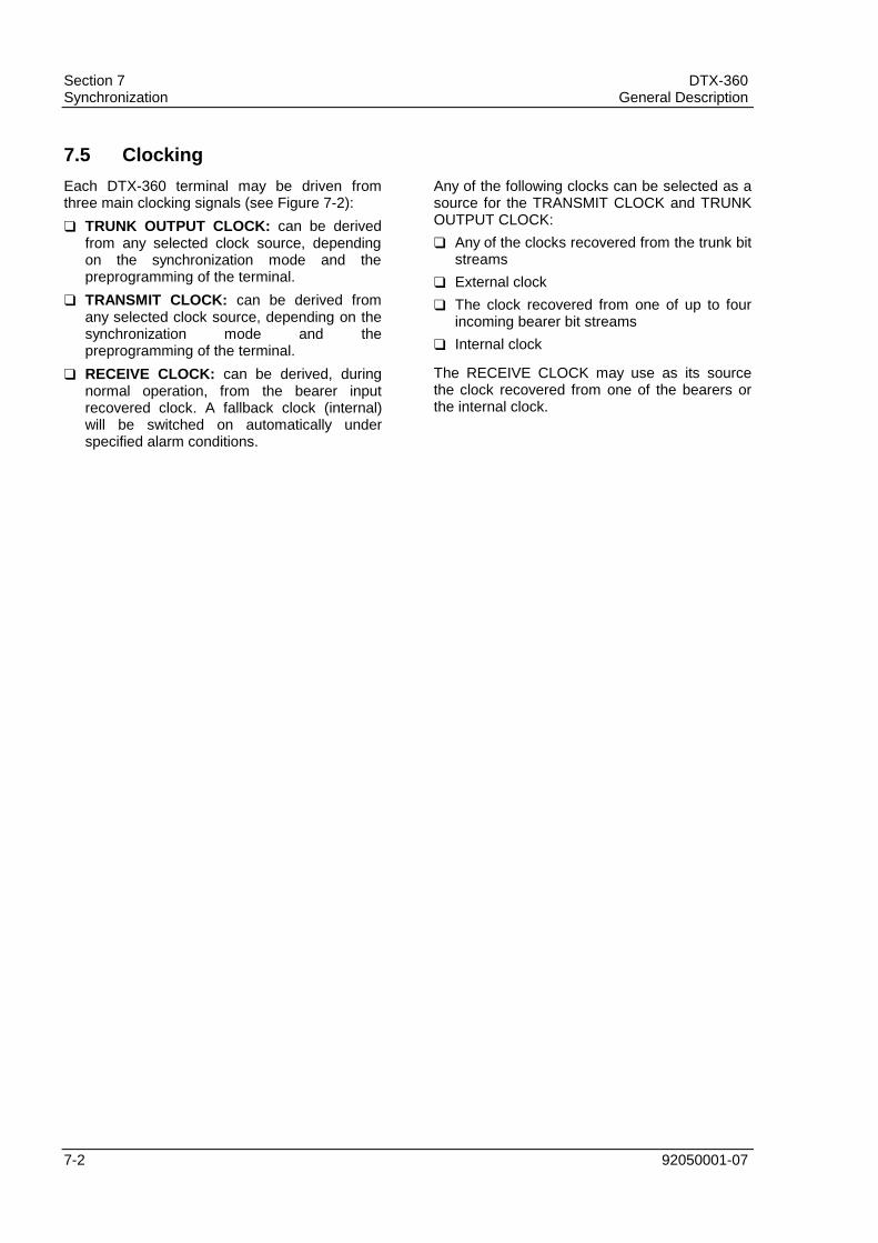
Section 7 DTX-360Synchronization General Description
7-2 92050001-07
7.5 Clocking
Each DTX-360 terminal may be driven fromthree main clocking signals (see Figure 7-2):
TRUNK OUTPUT CLOCK: can be derivedfrom any selected clock source, dependingon the synchronization mode and thepreprogramming of the terminal.
TRANSMIT CLOCK: can be derived fromany selected clock source, depending on thesynchronization mode and thepreprogramming of the terminal.
RECEIVE CLOCK: can be derived, duringnormal operation, from the bearer inputrecovered clock. A fallback clock (internal)will be switched on automatically underspecified alarm conditions.
Any of the following clocks can be selected as asource for the TRANSMIT CLOCK and TRUNKOUTPUT CLOCK:
Any of the clocks recovered from the trunk bitstreams
External clock
The clock recovered from one of up to fourincoming bearer bit streams
Internal clock
The RECEIVE CLOCK may use as its sourcethe clock recovered from one of the bearers orthe internal clock.

DTX-360 Section 7General Description Synchronization
92050001-07 7-3
Figure 7-1. DTX-360 Synchronization Modes

Section 7 DTX-360Synchronization General Description
7-4 92050001-07
Figure 7-2. DTX-360 - System Clocks

92050001-07 8-1
8
MAINTENANCE FACILITIES8.1 Functions
The DTX-360 provides a complete package ofin-service functions in support of maintenancetasks to assure uninterrupted service.
The following in-service functions are available:
Local Built-In-Test
Terminal Internal Redundancy
System Clock Monitoring
Control Channel BER Monitoring
Trunk and Bearer Error Performance
System Statistics
System Anomaly Reports
Terminals Alarm Condition Indications(Acoustic and Visual)
Terminal Alarm Condition Outputs
End-to-End Tests
Communication Link Monitoring
Standby Terminal for Cluster Mode
System reports in the DTX-360 can begenerated both locally and remotely. In bothcases, the reports are based on events thathave been logged in the DTX-360 terminals aswell as the Operator Station and can begenerated automatically or on demand.
The system continuously chronicles, compiles,and stores information required to generatereports and provide the following services:
Assist maintenance personnel in diagnosingand locating faults or abnormal conditions.
Provide status, traffic and performanceinformation related to facilities andequipment, aimed at monitoring terminal andoverall system performance.
Each DTX-360 terminal generates reports when:
An operator requests a report
An operator's predefined time-interval haselapsed
A pre-defined system time interval, such asdaily automatic period (once every 24 hours)has elapsed
All automatic reports can be enabled or disabledby the operator. These reports provide thefollowing general information:
Report designation
Report cause (operator's request, time-interval, etc.)
System identification
System configuration
Date and time

Section 8 DTX-360Maintenance Facilities General Description
8-2 92050001-07
8.2 Built-In-Test
The DTX-360 terminal subsystems andfunctions are self-checked by an internal Built-In-Test packet.
The self-check procedures include tests onhardware and software facilities during normaloperations, without interference or impact ontraffic carrying capacity.
Any fault detection is reported to the OMCP toinitiate corrective and protective measures.
8.3 Terminal Alarms
The DTX-360 terminal alarms fall into four (4)categories:
Critical: Critical alarms are a subgroup of theprompt alarms. They are used by theredundancy control unit to initiate automaticswitch over to a redundant terminal. Criticalalarms are issued when a traffic-affecting,internal equipment failure occurs.
Prompt: A prompt alarm condition is raisedfollowing the detection of a fault requiringimmediate maintenance attention.
Deferred: A deferred alarm condition israised following the detection of a fault whichdoes not require immediate maintenanceattention.
Service: A service alarm condition is raisedwhen the terminal is informed of theoccurrence of an external fault.
8.4 DTX-360 Display Panel (AUXCard Panel)
The DTX-360 AUX card enables the followingman-machine functions:
Indication of Terminal Alarms
System Status Display
Alarm Cut-Off
Order Wire Communication
8.4.1 Terminal Alarm Indications
Terminal alarm conditions, prompt, deferred, orservice, are visually indicated by correspondingred LEDs on the front panel of the AUX card.
8.4.2 Alphanumeric Display
The Alphanumeric display provides visualinformation related to the following conditions:
System Status (i.e., on-line normal, on-linefaulty, off-line normal, off-line faulty,maintenance, etc.)
Terminal Built-In-Test Alarm
8.4.3 Order Wire Call Indicators
Four (4) LEDs are provided to indicate anincoming voice order wire call (one LED perdestination).
8.4.4 Order Wire Buzzer
While an unattended call is waiting, it is possibleto activate an acoustic buzzer.
8.4.5 Handset
A 4-wire handset with touch-tone facility is usedto enable voice order wire communication.
8.4.6 Test Port (Drop & Insert)
This port provides the capability of connectingany internal intermediate trunk (IT) to an analogtest generator/receiver.
Assignments to this test port are possible onlythrough the configuration map.
8.4.7 Power On/Off Switch
Access to this switch is protected to preventaccidental activation. The switch is equippedwith a LED indicator to provide visual display ofON/OFF condition.
8.5 System Reset
A protected-access system reset pushbutton isprovided on the front panel of the OMCP card.

DTX-360 Section 8General Description Maintenance Facilities
92050001-07 8-3
Figure 8-1. DTX-360 AUX Card

92050001-07 9-1
9
TECHNICAL SPECIFICATIONS
9.1 General
CE MARKING
The DTX-360 product is certified for CE.
The product was tested according to RC5000N specification, referring to EN55022 CLASS A limits.
WARNING
This is a Class A product. In a domestic environment this product may cause radio interference, in whichcase the user may be required to take adequate measures.
Note: A DOMESTIC ENVIRONMENT is an environment where the use of broadcast radio and television receiversmay be expected within a distance of 10 meters of the product.
The following table contains a summary of the DTX-360 technical specifications.
FUNCTION SPECIFICATIONS
DCME MODES - IESS-501 REV.3, ITU REC. G.763 - G.766- IESS-501 REV.2- LD-CELP
NETWORK MODES - Single-Destination (SD)- Multi - Destination (MD)- Multi-Clique (MC)- Interoperation (Mixed MC and MD)
COMPRESSION RATIO - * 5:1 Typical for 150 trunks (40% FAX)- ** 8:1 Typical for 240 trunks (40% FAX)
CHANNEL CAPACITY- Trunk Channels: Max. 360- Intermediate Trunks (Processed Trunks): * MAX. 216 ** MAX. 360- Bearer Channels: * Max. 122 (61 Normal + 61 Overload) ** Max. 200 (120 Normal + 80 Overload)
NOTE: * For DTX - 360 in ITU G.763 and G.766 Configuration (IESS - 501, REV 3 Mode)
** For DTX - 360 in LD-CELP Configuration

Section 9 DTX-360Technical Specifications General Description
9-2 92050001-07
FUNCTION SPECIFICATIONS
DIGITAL GROUP INTERFACE - Trunk Side Interface: DTX-360: Up to 12 CEPT (2.048 Mbit/s) or 12 T1 (1.544 Mbit/s) interfaces DTX-360 (Compact): Up to 8 CEPT (2.048 Mbit/s) or 18 T1(1.544 Mbit/s) interfaces- Bearer Side Interface: DTX-360: One Tx bearer and up to 4 Rx bearers (CEPT or T1) DTX-360 (Compact): One Tx bearer and up to 4 Rx bearers (CEPTor T1)- CEPT Interface: ITU G.703, 120 or 75 Ω. Framing complies with G.704-G.706- T1 Interface: ITU G.703, 100 Ω. Framing complies with G.704
EXTERNAL CLOCKINTERFACE
- 2.048 kbit/s According to ITU G.703
PLESIOCHRONOUS BUFFER - Trunk side Tx = 2 PCM frames- Trunk side Rx = 2 PCM frames- Bearer side Rx = 2 PCM frames
BEARER SERVICES - Voice: 1) Dynamically Assigned Channel * ADPCM (ITU G.726) at 32/24/16 kbit/s ** LD-CELP at 16/12.8/9.6 kbit/s 2) Pre-Assigned Channel * ADPCM at 32 kbit/s ** LD-CELP at 16/12.8/9.6 kbit/s- VBD (NON-FAX): 1) Dynamically Assigned Channel * ADPCM (ITU G.726) at 40 kbit/s; V.32, V.34 - up to 14.4 kbit/s ** LD-CELP at 40 kbit/s ; V.32, V.34 - up to 19.2 kbit/s 2) Pre-Assigned Channel (fixed rate) * ADPCM at 40/32 kbit/s ** LDCELP at 40/16 kbit/s- VBD (Group 3 FAX): 32 kbit/s Transparent Fax Banks according to ITU G.766 (Forward Error Correction selectable)- 64 kbit/s: 1) Dynamically Assigned Channel (Q.50 protocol required) 2) Pre-Assigned Channel at 64 kbit/s rate- N*64kbit/s: N Pre-Assigned Channels at 64 kbit/s rate
SPEECH DETECTOR - Adaptive Threshold (-30 to -40 dBm0)
NOISE INJECTION - Matched to far end (ITU G.763)
FACSIMILE CALLPROCESSING
- FAX Demodulation by waveform analysis (ITU G.766)- Group 3 Facsimile, standard and non-standard protocols are demodulated: Up to 180 V.29/V.27/V.17 fax calls
DCME-ISC LINK - ITU Q.50 protocol via T.S.16 1) Q.50 type 1 2) Q.50 type 2, Annex A 3) Q.50 type 2, Annex B- DLC dry contacts (per destination)
INTER-EXCHANGESIGNALING
- ITU Sign. System No. 5, via dynamically assigned channel- ITU Sign. System No. 6 or 7, via pre-assigned 64 kbit/s channel- DPNSS signaling supported on TS 16 as well as other time slots- ITU R2 D, via R2 D User Signaling Module- ITU R1 via optional User Signaling Module
NOTE: * For DTX - 360 in ITU G.763 and G.766 Configuration (IESS - 501, REV 3 Mode)
** For DTX - 360 in LD-CELP Configuration

DTX-360 Section 9General Description Technical Specifications
92050001-07 9-3
FUNCTION SPECIFICATIONS
ALARM INTERFACE - Relay closures for visual and audio alarms- Alarm classification: Prompt, Deferred, Service
DIGITAL OFFICE MONITOR(DOM) INTERFACE OPTION
- RS-485
VOICE ORDER WIRE (VOW)INTERFACE
- 4 -Wire 600 Ω interface (per destination)- VOW is accessible via handset on DTX-360 front panel
DTX-360 TERMINALPROTECTION
- N+1 (N=1-8) cluster protection switching by means of Change Over Matrix
DTX-360 TERMINALOPERATION &MAINTENANCE
- Sun (or Sun-compatible) Operator Station (OPS)- OPS may operate 1-8 DTX-360 clusters
CLUSTER COMMUNICATIONLINK (OPS, DTX-360, CCOM)
- Ethernet 10 Base-2 or Ethernet 10 Base-T
POWER REQUIREMENTS 1) Input power: -48V DC or -60V DC Station Power (input voltage range = -40.5 to -72 Volts DC)2) Power consumption: * DTX-360 ADPCM = 240W DTX-360 LD-CELP = 350W Local COM (LCOM) = 58W Central COM (CCOM) = 63W
DIMENSIONS Cabinet dimensions: Width: 655mm (25.75 inches) Height: 2134mm (84 inches) or 2600mm (102 inches) Depth: 450mm (17.75 inches)Cabinet Weight: 45U - 66Kg 54U - 77KgShelf dimensions: Width: DTX-360: 584mm (23 inches) DTX-360C: 584mm (23 inches) Local COM: 584mm (23 inches) Central COM: 584mm (23 inches) Height: DTX-360: 533mm (21 inches) DTX-360C: 266mm (10.5 inches) Local COM: 266mm (10.5 inches) Central COM: 266mm (10.5 inches) Depth: DTX-360: 375mm (15 inches) DTX-360C: 375mm (15 inches) Local COM: 330mm (13.2 inches) Central COM: 330mm (13.2 inches)Shelf Weights: DTX-360 (12U) - 26Kg LCOM, CCOM - 10Kg (each) DTX-360C - 18Kg
ENVIRONMENTALCONDITIONS
- Operation: 1) Ambient temperature: 0°C to +40°C 2) Humidity: up to 90% at 30°C without condensation- Storage: 1) Ambient temperature: -40°C to +70°C 2) Humidity: From 5% to 95% R.H
ELECTROMAGNETICCOMPATABILITY
- Complies with: RC5000N Part 1 (British Telecom) VDE 0878 Part 1, Class B
ESD - Complies with: RC5000N Part 1 (British Telecom) FTZ 12 TR1 Part 40 (German Telecom)
NOTE: * For DTX - 360 in ITU G.763 and G.766 Configuration (IESS - 501, REV 3 Mode)
** For DTX - 360 in LD-CELP Configuration

Section 9 DTX-360Technical Specifications General Description
9-4 92050001-07

92050001-07 10-1
10
GLOSSARY OF TERMS
ADPCM - Adaptive Differential Pulse CodeModulation
ADPC - Adaptive Differential PCMEncoder/Decoder
ACO - Alarm Cut-Off
AIS - Alarm Indicator Signal
AMI - Alternate Mark Inversion
AUXL - Auxiliary Card
BC - Bearer Channel
BER Bit Error Rate
BR - Bearer
BIT - Built-in Test
BMCT - Bit Map CPU - Transmit
BMCR - Bit Map CPU - Receive
CCOM - Central Change Over Matrix
CC - Clear Channel (Transparent Channel)
CKSL - Clock Select
COCP - Change Over Central Processor
CRMX - Central Relay Matrix
CRIO - Central Relay Input-Output Interface
DCME- Digital Circuit MultiplicationEquipment
DCMS - Digital Circuit Multiplication System
DCOM - Distributed Change Over Matrix
DSIT - Digital Speech Interpolation -Transmit
DSIR - Digital Speech Interpolation - Receive
DLC - Dynamic Load Control
DLI - Digital Line Interface
DSI - Digital Speech Interpolation
FAX - Facsimile
FEC - Forward Error Correction
FDSP - Fax Demodulator
IDR - Intermediate Data Rate
ISC - International Switching Center
ISL - Incoming Signal Loss
IT - Intermediate Trunk
LCOM - Local Change Over Matrix
LD-CELP - Low Delay - Code Excited LinearPrediction
LDCH (T) - Low Delay - Code Excited LinearPrediction card - Encoder (Transmit)
LDCH (R) - Low Delay - Code Excited LinearPrediction card - Decoder (Receive)
LODP - Local Operator Display Panel
LRE - Low Rate Encoding
LRMX - Local Relay Matrix
MC - Multi Clique

Section 10 DTX-360Glossary of Terms General Description
10-2 92050001-07
MD - Multi Destination
MTBF - Mean Time Between Failures
MTTR - Mean Time To Repair
NRZ - Non-Return to Zero
OPS - Operator Station
OMCP - Operation and Maintenance CPU
OW - Order Wire
PCM - Pulse Code Modulation
PSU - Power Supply Unit
QDLI - Quad Digital Line Interface
RAI - Remote Alarm Indication
RCPU - Receive CPU
RDSP - Receive Remodulator (Fax)
RDSW - Redundancy Switch
RX - Receive
SCOM - Single Cabinet Change Over Matrix
SCPU - Signal Analysis CPU
SDSP - Signal Analysis DSP
SIGN - Signaling CPU
TCPU - Transmit CPU
TC - Trunk Channel
TDMA - Time Division Multiple Access
TSDF - Time Slot Interchange and DCME Frame Alignment
TDSP - Transmit Demodulator (Fax) DSP
TX - Transmit
TSI - Time Slot Interchange
TR - Trunk
VBR - Variable Bit Rate
VBD - Voice-Band Data
VOW - Voice Order Wire
ZCS - Zero Code Suppression