DTL Blender - SPX FLOW · dtl blender form no.: 95-03037 revision: 02/2007 read and understand this...
26
DTL Blender FORM NO.: 95-03037 REVISION: 02/2007 READ AND UNDERSTAND THIS MANUAL PRIOR TO OPERATING OR SERVICING THIS PRODUCT. INSTRUCTION MANUAL FPO
Transcript of DTL Blender - SPX FLOW · dtl blender form no.: 95-03037 revision: 02/2007 read and understand this...

DTL Blender
FOR M NO.: 95-03037 R EVI S ION: 02/2007 R EAD AN D U N D E R STAN D TH I S MAN UAL PR IOR TO OPE RATI NG OR S E RVICI NG TH I S PROD UCT.
I N STR UCTION MAN UAL
FPO

611 Sugar Creek RoadDelavan, WI 53115 USA
Tel: (800) 252-5200 or (262) 728-1900Fax: (800) 252-5012 or (262) 728-4904
E-mail: [email protected] site: www.spx.com
Information contained in this manual is subject to changewithout notice and does not represent a commitment on thepart of SPX. No part of this manual may be reproduced ortransmitted in any form or by any means, electronic ormechanical, including photocopying and recording, for anypurpose, without the express written permission of SPX.
Copyright © 2007 All Rights Reserved.
Issued Date: December 22, 2000
Revised Date: February 2007
Publication: 95-03037

Table of ContentsWaukesha Cherry-Burrell Warranty ................................................................................4
Shipping Damage or Loss .............................................................................4Warranty Claim .............................................................................................4
Safety.....................................................................................................................................5Introduction..........................................................................................................................6
Description ...............................................................................................................6Installation............................................................................................................................7
Unpacking ................................................................................................................7Receiving and Inspection ........................................................................................7Location and Installation .......................................................................................7Piping .......................................................................................................................7
Maintenance .........................................................................................................................8Cleaning ...................................................................................................................8
Disassembly for Cleaning .............................................................................8C.I.P. Cleaning ..............................................................................................8
DTL Blender Disassembly ......................................................................................9External Balanced Type D, F. Dg Seals: ..........................................9Water Cooled Balanced Double Seal Type E: ..................................9
Deflector and Stub Shaft Removal ........................................................................10Shaft and Motor Removal (Model WP3218MD) .................................................10
Model WP2116MD Assembly ......................................................................11Model WP3218MD Assembly ......................................................................11
Disassembly of the Butterfly Valve .......................................................................12Setting the Drive Collar ..........................................................................................12
Blenders With D, F. Or DG Seals .................................................................12Install the deflector on the shaft. .......................................................12Setting The Drive Collar By Position ...............................................12Blenders With E Seals ......................................................................13
Care of Stainless Steel..........................................................................................................14Stainless Steel Corrosion ..............................................................................14Alloy 88 ........................................................................................................14Elastomer Seal Replacement Following Passivation ....................................14
Troubleshooting ...................................................................................................................15

Warranty Waukesha Cherry-Burrell
Page 4 95-03037 February 2007
Waukesha Cherry-Burrell Warranty
Seller warrants its products to be free from defect in materials and workmanship for a period of one (1) year from the date of shipment. This warranty shall not apply to products which require repair or replacement due to normal wear and tear or to products which are subjected to accident, misuse or improper maintenance. This warranty extends only to the original Buyer. Products manufactured by others but furnished by Seller are exempted from this warranty and are limited to the original manufacturer’s warranty.
Seller’s sole obligation under this warranty shall be to repair or replace any products that Seller determines, in its discretion, to be defective. Seller reserves the right either to inspect the products in the field or to request their prepaid return to Seller. Seller shall not be responsible for any transportation charges, duty, taxes, freight, labor or other costs. The cost of removing and/or installing products which have been repaired or replaced shall be at Buyer’s expense.
Seller expressly disclaims all other warranties, express or implied, including without limitation any warranty of merchantability of fitness for a particular purpose. The foregoing sets forth Seller’s entire and exclusive liability, and Buyer’s exclusive and sole remedy, for any claim of damages in connection with the sale of products. In no event shall Seller be liable for any special consequential incidental or indirect damages (including without limitation attorney’s fees and expenses), nor shall Seller be liable for any loss of profit or material arising out of or relating to the sale or operation of the products based on contract, tort (including negligence), strict liability or otherwise.
Shipping Damage or Loss
If equipment is damaged or lost in transit, file a claim at once with the delivering carrier. The carrier has signed the Bill of Lading acknowledging that the shipment has been received from WCB in good condition. WCB is not responsible for the collection of claims or replacement of materials due to transit shortages or damages.
Warranty Claim
Warranty claims must have a Returned Goods Authorization (RGA) from the Seller before returns will be accepted.
Claims for shortages or other errors, exclusive of transit shortages or damages, must be made in writing to Seller within ten (10) days after delivery. Failure to give such notice shall constitute acceptance and waiver of all such claims by Buyer.

Waukesha Cherry-Burrell Safety
February 2007 95-03037 Page 5
SafetyREAD AND UNDERSTAND THIS MANUAL
PRIOR TO INSTALLING, OPERATING OR SERVICING THIS EQUIPMENT
Waukesha Cherry-Burrell recommends users of our equipment and designs follow the latest Industrial Safety Standards. At a minimum, these should include the industrial safety requirements established by:
1. Occupational Safety and Health Administration (OSHA), Title 29 of the CFR Section 1910.212- General Requirements for all Machines
2. National Fire Protection Association, ANSI/NFPA 79 ANSI/NFPA 79- Electrical Standards for Industrial Machinery
3. National Electrical Code, ANSI/NFPA 70 ANSI/NFPA 70- National Electrical Code ANSI/NFPA 70E- Electrical Safety Requirement for Employee Workplaces
4. American National Standards Institute, Section B11
Attention: Servicing energized industrial equipment can be hazardous. Severe injury or death can result from electrical shock, burn, or unintended actuation of controlled equipment. Recommended practice is to disconnect and lockout industrial equipment from power sources, and release stored energy, if present. Refer to the National Fire Protection Association Standard No. NFPA70E, Part II and (as applicable) OSHA rules for Control of Hazardous Energy Sources (Lockout-Tagout) and OSHA Electrical Safety Related Work Practices, including procedural requirements for:
• Lockout-tagout• Personnel qualifications and training requirements• When it is not feasible to de-energize and lockout-tagout electrical circuits and equipment before working on or near
exposed circuit partsLocking and Interlocking Devices: These devices should be checked for proper working condition and capability of performing their intended functions. Make replacements only with the original manufacturer’s renewal parts or kits. Adjust or repair in accordance with the manufacturer’s instructions.
Periodic Inspection: Industrial equipment should be inspected periodically. Inspection intervals should be based on environmental and operating conditions and adjusted as indicated by experience. At a minimum, an initial inspection within 3 to 4 months after installation is recommended. Inspection of the electrical control systems should meet the recommendations as specified in the National Electrical Manufacturers Association (NEMA) Standard No. ICS 1.3, Preventative Maintenance of Industrial Control and Systems Equipment, for the general guidelines for setting-up a periodic maintenance program.
Replacement Equipment: Use only replacement parts and devices recommended by the manufacturer to maintain the integrity of the equipment. Make sure the parts are properly matched to the equipment series, model, serial number, and revision level of the equipment.
Warnings and cautions are provided in this manual to help avoid serious injury and/or possible damage to equipment:
DANGER: marked with a stop sign. Immediate hazards which WILL result in severe personal injury or death.
WARNING: marked with a warning triangle. Hazards or unsafe practices which COULD result in severe personal injury or death.
CAUTION: marked with a warning triangle. Hazards or unsafe practices which COULD result in minor personal injury or product or property damage.

Introduction Waukesha Cherry-Burrell
Page 6 95-03037 February 2007
Introduction
Description
The DTL Blender is designed to introduce a dry material to a liquid and through a mechanical action provide a blended end product for a process.
The DTL Blender has two sections, the dry material section and the liquid material section.
The DTL Blender model WP3218MD is mounted on a base plate. The blender is driven by belts located under the base plate. These belts are driven by the drive motor mounted next to the blender assembly. A electrically controlled butterfly valve and control panel are standard equipment on model WP3218MD. The control panel may be mounted directly to the DTL Blender base, or a remote location.
The DTL Blender model WP2116MD is mounted, on a base plate, with the drive motor mounted to the underside of the base plate. The motor shaft which extends through the base plate into the stub shaft secured to the impeller. Material flow is controlled with a hand operated butterfly valve. Optional electrically or pneumatically controlled valves are also available.
All piping connections are made with quick couple S-Clamps. The support legs are adjustable for leveling of the blender during installation.

Waukesha Cherry-Burrell Installation
February 2007 95-03037 Page 7
Installation
Unpacking
The model WP3218MD DTL Blender is packed in two separate shipping containers, the hopper is in one crate, the Blender and its components are packaged in another crate. The blender and drive motor are mounted to the base plate which is secured to a wood pallet.
The adjusting legs and clamps are in a bag packed with the blender.
The control box and the control valve are packaged in a separate carton.
Model WP2116MD DTL Blender is shipped in one container.
Receiving and Inspection
WCB equipment is run tested or inspected prior to shipment. When leaving the factory, it is well crated for normal transportation procedures. WCB cannot, however, guarantee safe arrival. Therefore, upon receipt of this equipment, check the received items against the packing list for damage or missing parts. Check the packing material thoroughly for small parts.
Visually inspect for damage or loss. Damage or loss should be reported immediately to the delivery carrier while present. Following the immediate notification of the lost or damaged parts, a detailed description including quantity, description of the loss or damage, and a cash value should be claimed against the carrier with respect to the guidelines set forth by the responsible carrier's policies. WCB's responsibility terminates F.O.B. point of manufacture unless otherwise specified per the General Terms and Conditions of Sale as published by WCB and amended from time to time. Contact WCB Order Services if shipping information is required for handling claims.
In the case of damage or loss to the equipment, WCB may perform three major functions:
Manufacturer Function - WCB manufactures quality equipment and stands behind the WCB Standard Warranty. Refer to the Standard Warranty.
Location and Installation
For best performance locate DTL Blender unit within 3 feet of the liquid source and in a position where the supply piping will be short and direct with a minimum number of elbows and fittings. When installing the unit consider accessibility for future cleaning and inspection.
To install the WP2116MD model a minimum space of 20" x 20" will be needed to accommodate the basic unit. For the WP3218MD model a minimum space of 32" x 47" will be needed. Install the adjustable legs in the base of the unit and position the blender in the area it will be used. Turn each adjusting leg with a wrench until the unit is level.
An auxiliary pump is required to supply the liquid to the blender.
Attach the supply and discharge piping. Be sure supply and discharge piping is properly supported to avoid strain on the blender casing.
The inlet connection on the model WP3218MD is 1-1/2" tube O.D. and the outlet on the impeller casing is 2" tube O.D. Be sure the inlet and outlet tubes are correctly positioned.
Piping
All piping is to be supplied and installed by the purchaser. Piping must be well supported near the unit and in line with connection fittings so that no strain is put on the fittings. The inlet piping should be short and follow a direct route. Elbows should not be used at the inlet. The use of elbows increases friction resulting in head loss and cavitation in the blender reducing performance, as well as increasing noise, vibration and damage to equipment. Whenever practical the diameter of the piping at the inlet should be increased in size. An eccentric tapered reducer, should be used in place of a straight concentric tapered reducer to help direct the flow into the offset tee to minimize turbulence. (For more information regarding reducers refer to Waukesha Fittings Catalog)

Maintenance Waukesha Cherry-Burrell
Maintenance
The DTL Blenders are relatively maintenance free, requiring normal cleaning and inspection to ensure optimum performance.
Cleaning
DANGER: ALWAYS turn off the electrical power supply and Lock Out, using a locking device for which only the person doing the work has the key, before performing service or maintenance.
WARNING: Hydrochloric acid, even with inhibitors added, is not recommended for cleaning stainless. (Inhibitors are specific compounds that are added to cleaning chemicals to diminish their corrosive effect on metals. Most inhibitors are proprietary, and recommendations for their use are available from the supplier).
It is necessary to disassemble all of the parts of the DTL Blender except the drive motor, for cleaning and sanitizing.
Disassembly for Cleaning
1. Disconnect the suction and discharge piping.
2. Remove the clamps securing the hopper to the blender.
3. Remove the clamps securing the butterfly valve end connections.
4. Disassemble the valve. “DTL Blender Disassembly” on page 9.
5. Remove each of the clamps and blender tubes in a top down sequence until all that remains is the impeller casing.
6. Grasp the impeller casing firmly in both hands and pull the casing up and off of the adaptor ring.
7. After disassembling the unit, rinse all parts with lukewarm water 100 F until all traces of ingredient and product are gone.
8. Brush the unit and all parts with a general purpose powered alkaline cleaning solution. Follow manufacturer's recommendations.
9. Immediately rinse the unit and parts with lukewarm water 100 F until all the detergent has been removed.
10. Rinse with hot water to facilitate quick drying and to eliminate water spotting.
11. Drain parts and allow them to air dry.
12. Inspect O-ring seals, and replace if necessary.
13. Before assembling the unit, apply sanitary lubricant to gaskets.
C.I.P. Cleaning
If the DTL Blender is to be cleaned-in-place, the butterfly valve must be removed and cleaned separately See “Disassembly of the Butterfly Valve” on page 12.In addition the dry ingredients inlet adaptor tube must be capped off.
NOTE: The impeller casing and backplate are separated by a gasket. Do not attempt to separate the two sections by inserting a tool and prying them apart. This could result in damage to the machined surfaces of the adaptor ring and the gasket. A firm tug on the casing will separate the casing from the unit.
Remove the screen from inside of the impeller casing. To clean the impeller and backplate, remove the bolt securing the impeller to the shaft. Lift the washer and impeller off of the shaft.
Clean all of the disassembled blender components.“Care of Stainless Steel” on page 14.
If during the cleaning process you notice any damaged or worn parts replace them before reassembling the unit.
Reassemble the blender using the reverse order of disassembly.
Page 8 95-03037 February 2007

Waukesha Cherry-Burrell Maintenance
DTL Blender Disassembly
It is recommended that periodic inspection of all parts of the DTL Blender be made to prevent malfunctions caused by worn or broken parts.
The following disassembly procedures cover the WP2116MD and WP3218MD models. Portions of the disassembly are identical for all models, but where differences occur the procedure for each model will be indicated.
NOTE: Disassembly varies depending on the type of seal used. There are four types of seals: D, F. DG, and E.
DANGER: ALWAYS turn off the electrical power supply and Lock Out, using a locking device for which only the person doing the work has the key, before performing service or maintenance.
1. Disconnect the suction and discharge piping.
2. Loosen the wing nut on the clamp, securing the hopper to the blender, until tension on the clamp saddle is relieved.
3. Open the clamp and remove the hopper and gasket.
4. Disconnect the clamp securing the control valve. Hold the valve while loosening the clamp, to prevent the valve from falling.
5. For repair and service of the butterfly valve on your blender see “Disassembly of the Butterfly Valve” on page 12
6. Remove the clamps on the top flange of the inlet adapter, and lift the diffuser and suction tube out of the inlet adapter.
7. Remove the clamp securing the inlet adapter to the impeller casing and remove the adapter and gasket.
8. Remove the large clamp securing the impeller casing to the backplate. Grasp the impeller casing firmly in both hands and pull the casing straight up and off of the backplate.
CAUTION: Do not use a tool to pry the casing off of the backplate. Any object inserted between the casing and gasket could cause damage to the gasket and casing sealing surface, resulting in a leak after reassembly.
9. Using a suitable wrench remove the bolt securing the impeller to the stub shaft. Remove the washer and impeller.
At this point, disassembly will vary, depending on the type of seal the blender has refer to the following procedures specific to your seal arrangement.
External Balanced Type D, F. Dg Seals:1. Rotate the backplate until the pins in the plate clear
the adapter pins.
2. Remove the backplate.
3. Carefully inspect the backplate, gasket, and impeller casing for nicks, scratches or signs of wear.
CAUTION: Use caution, when handling the backplate to avoid damage to the surfaces around the opening for the carbon seal.
• On DO models inspect the clamped-in seat for damage.
• On F models remove the water flush piping.
4. Remove the carbon seal, O-ring seal, cup, spring, and drive collar.
Water Cooled Balanced Double Seal Type E:1. Disconnect the water inlet and outlet from the
stuffing box.
2. Remove the four screws that retain the follower to the stuffing box.
3. Slide the stuffing box and backplate assembly off of the shaft.
4. Remove the inboard carbon seal, seal O-ring, cup and the seal spring from the shaft.
February 2007 95-03037 Page 9

Maintenance Waukesha Cherry-Burrell
Deflector and Stub Shaft Removal
1. Loosen the two set screws and remove the drive collar. The remaining carbon seal, seal O-ring, cup and the follower may now be removed from the shaft.
2. When removing the drive motor from the base plate, place a suitable block beneath the motor and turn the adjustable legs until the motor rests firmly on the block.
3. To remove deflector, lift straight off.
4. Remove the four nuts, bolts, and lock washers securing the motor to the base plate.
5. With the motor resting on the blocks, lift the base plate off of the motor, leaving the stub shaft attached to the motor.
6. Loosen the two setscrews securing the stub shaft to the motor armature shaft.
7. Remove the stub shaft by prying beneath it with a flat bar.
8. Examine the stub shaft sealing surface for nicks, or scratches which can cause excessive O-ring seal wear or leakage.
9. To remove the adaptor ring and spacers from the blender base, set the base on its side.
10. Remove the six socket head screws in the bottom of the base. While removing the socket head screws hold the adaptor to prevent it from falling.
11. Remove the adjustable legs from the blender base. Inspect the O-rings for damage.
12. To assemble see assembly procedures in this manuals for your particular model.
Shaft and Motor Removal (Model WP3218MD)
When removing the drive components, it is necessary to tip the entire blender and base on its side, with the motor end toward the floor. To ease the lifting of the unit remove all of the components possible before tipping.
1. Loosen the mounting bolts securing the drive motor to the base. The bolt holes are elongated to permit belt adjustment.
2. Slide the motor toward the blender and remove the drive belts.
NOTE: When replacing drive belts allow 3/4" deflection (slack).
3. Remove the three bolts securing the blender pulley. Use the same three bolts as forcing screws and thread them into the forcing holes, finger tight.
4. Turn each bolt an equal amount, alternating bolts until the pulley releases from the bushing.
5. Remove the forcing screws and remove the pulley.
6. Slide the tapered bushing from the shaft.
7. Loosen the setscrews securing the collar to the shaft and remove the deflector collar.
8. Loosen the six capscrews securing the adapter ring spacers. Hold the adapter ring to prevent it from falling.
9. Remove the capscrews and remove the adapter and spacers.
10. Set the blender down on its legs.
11. Remove the four capscrews securing the bearing housing to the base plate.
12. Grasp the bearing housing firmly in both hands, and lift it out of the blender base.
13. Remove the retaining ring and press the shaft out of the housing.
14. Using puller, remove the bearing from the shaft and remove the other bearing from the housing.
15. Inspect the shaft sealing surface for nicks or scratches.
16. Inspect all of the components for cracks and distortion. Inspect the adjusting legs for worn threads and damaged O-rings.
17. Replace any worn or damaged components.
NOTE: The two bearings in the bearing housing are sealed and lifetime lubricated. If either of the bearings are worn or damaged make certain they are replaced with exactly the same type of bearings, and replaced as a set.
Page 10 95-03037 February 2007

Waukesha Cherry-Burrell Maintenance
Model WP2116MD Assembly
1. Install the adjusting legs into the base.
2. Install the ring adapter onto the base plate, place the base plate on top of the motor and install the motor.
3. Place the motor mounting screws (4) in position. Attach the nuts and washers, but do not tighten them securely at this time. The motor must remain loose enough to allow alignment of the motor stub shaft in the backplate.
4. Align the setscrew in the stub shaft with the key on the motor armature and slide the stub shaft down.
5. Place the backplate over the stub shaft and position the impeller on the shaft. Approximately 1/16 inch clearance should be between the backplate and the impeller. The setscrews on the stub shaft may now be tightened securely.
6. Remove the impeller and observe the position of the stub shaft in the backplate. If the stub shaft is not centered in the backplate, move the motor in the proper direction.
7. When the stub shaft is centrally located in the backplate, tighten the motor mounting screws (4) securely.
8. See “Setting the Drive Collar” on page 12
9. Assemble the impeller, retainer, mounting bolt, and casing gasket.
10. Place the impeller casing firmly on the backplate and seal the two together with the large clamp.
11. Assemble the remaining tubes and seals securing each section with the proper size clamps.
NOTE: For correct positioning of the inlet adapter, refer to the exploded view pages for appropriate models in the parts section of this manual
12. Install the control valve and the hopper.
13. Connect all the suction and discharge piping.
Model WP3218MD Assembly
1. Install the bearing housing on top of the base plate.
2. Tip the blender on end and install the adapter ring.
3. Install the blender pulley key and bushing.
4. Place the pulley in position and be certain to use the correct mounting holes for the bolts securing the pulley; make sure that both pulleys are horizontally aligned.
5. Draw the pulley tight with the mounting bolts by alternately tightening each bolt a small amount until all three bolts are tight.
6. Place the drive belts on the motor pulley and the blender pulley. It may be necessary to move the motor toward the blender housing to place the belts on the pulleys.
7. Adjust the belts by moving the drive motor away from the blender housing until 3/4 inch of slack remains in the belts.
8. Secure the motor.
9. See “Setting the Drive Collar” on page 12
10. Assemble the impeller, retainer, mounting bolt, and casing gasket.
11. Place the impeller casing firmly on the backplate and seal the two together with the large clamp.
12. Assemble the remaining tubes and seals securing each section with the proper size clamps.
NOTE: For correct positioning of the inlet adapter, refer to the exploded view pages for appropriate models in the parts section of this manual.
February 2007 95-03037 Page 11
Maintenance Waukesha Cherry-Burrell
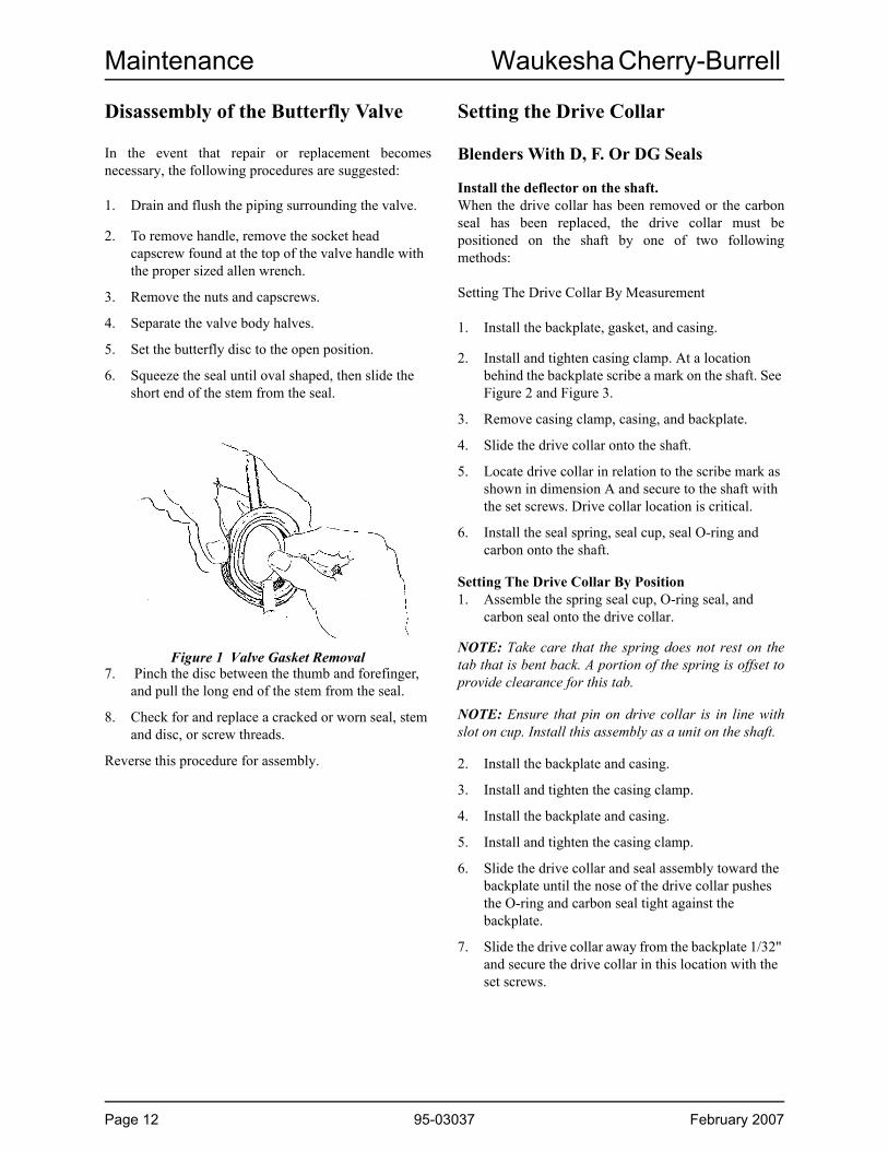
Disassembly of the Butterfly Valve
In the event that repair or replacement becomes necessary, the following procedures are suggested:
1. Drain and flush the piping surrounding the valve.
2. To remove handle, remove the socket head capscrew found at the top of the valve handle with the proper sized allen wrench.
3. Remove the nuts and capscrews.
4. Separate the valve body halves.
5. Set the butterfly disc to the open position.
6. Squeeze the seal until oval shaped, then slide the short end of the stem from the seal.
Figure 1 Valve Gasket Removal 7. Pinch the disc between the thumb and forefinger,
and pull the long end of the stem from the seal.
8. Check for and replace a cracked or worn seal, stem and disc, or screw threads.
Reverse this procedure for assembly.
Setting the Drive Collar
Blenders With D, F. Or DG Seals
Install the deflector on the shaft.When the drive collar has been removed or the carbon seal has been replaced, the drive collar must be positioned on the shaft by one of two following methods:
Setting The Drive Collar By Measurement
1. Install the backplate, gasket, and casing.
2. Install and tighten casing clamp. At a location behind the backplate scribe a mark on the shaft. See Figure 2 and Figure 3.
3. Remove casing clamp, casing, and backplate.
4. Slide the drive collar onto the shaft.
5. Locate drive collar in relation to the scribe mark as shown in dimension A and secure to the shaft with the set screws. Drive collar location is critical.
6. Install the seal spring, seal cup, seal O-ring and carbon onto the shaft.
Setting The Drive Collar By Position1. Assemble the spring seal cup, O-ring seal, and
carbon seal onto the drive collar.
NOTE: Take care that the spring does not rest on the tab that is bent back. A portion of the spring is offset to provide clearance for this tab.
NOTE: Ensure that pin on drive collar is in line with slot on cup. Install this assembly as a unit on the shaft.
2. Install the backplate and casing.
3. Install and tighten the casing clamp.
4. Install the backplate and casing.
5. Install and tighten the casing clamp.
6. Slide the drive collar and seal assembly toward the backplate until the nose of the drive collar pushes the O-ring and carbon seal tight against the backplate.
7. Slide the drive collar away from the backplate 1/32" and secure the drive collar in this location with the set screws.
Page 12 95-03037 February 2007

Waukesha Cherry-Burrell Maintenance
Blenders With E Seals1. Install the backplate, gasket, and casing.
2. Install and tighten casing clamp. At a location behind the backplate scribe a mark on the shaft. See Figure C.
3. Remove casing clamp, casing, and backplate.
4. Slide the follower, one carbon seal, one seal O-ring, one seal cup, and drive collar onto the shaft.
5. Locate drive collar in relation to the scribe mark as shown in Figure C and secure to the shaft with the set screws.
NOTE: Drive collar location is critical.
6. Install the seal spring, seal cup, seal O-ring and carbon onto the shaft. Be sure the spring is seated in each cup and the drive ear on each seal cup is not in alignment with the drive pins on the drive collar.
7. Slide the stuffing box and backplate assembly over the shaft and seal parts.
8. Secure the follower to the stuffing box using four screws.
NOTE: All Seals: With backplate and casing installed, and casing clamp tightened, the blender shaft should rotate freely by hand. If excessive effort is required to rotate the shaft, check to be sure that all components are properly installed, and that the drive collar is properly positioned.
9. Assemble seal guard and tighten nut.
Type E: attach the water inlet and outlet to the stuffing box.
After setting instructions have been completed, return to the assembly instructions for your configuration on preceding pages.
Table 1: Dimensions chart for Figure 2, Figure 3, Figure 4
Model A Dimensions
F2116 23/64
F3218 23/64
Figure 2 D,F Seals
Figure 3 DG Seal
Figure 4 E Seal
c
February 2007 95-03037 Page 13

Care of Stainless Steel Waukesha Cherry-Burrell
Page 14 95-03037 February 2007
Care of Stainless Steel
Stainless Steel Corrosion
Corrosion resistance is greatest when a layer of oxide film is formed on the surface of stainless steel. If film is disturbed or destroyed, stainless steel becomes much less resistant to corrosion and may rust, pit or crack.
Corrosion pitting, rusting and stress cracks may occur due to chemical attack. Use only cleaning chemicals specified by a reputable chemical manufacturer for use with 300 series stainless steel. Do not use excessive concentrations, temperatures or exposure times. Avoid contact with highly corrosive acids such as hydrofluoric, hydrochloric or sulfuric. Also avoid prolonged contact with chloride-containing chemicals, especially in presence of acid. If chlorine-based sanitizers are used, such as sodium hypochlorite (bleach), do not exceed concentrations of 150 ppm available chlorine, do not exceed contact time of 20 minutes, and do not exceed temperatures of 104°F (40°C).
Corrosion discoloration, deposits or pitting may occur under product deposits or under gaskets. Keep surfaces clean, including those under gaskets or in grooves or tight corners. Clean immediately after use. Do not allow equipment to set idle, exposed to air with accumulated foreign material on the surface.
Corrosion pitting may occur when stray electrical currents come in contact with moist stainless steel. Ensure all electrical devices connected to the equipment are correctly grounded.
Alloy 88
Waukesha Alloy 88 is the standard rotor material for Universal I, Universal II, Universal Lobe, Universal 420/520 and 5000 Series Rotary PD pumps. This alloy was developed specifically for corrosion resistance and close operating clearance requirements of high performance rotary positive displacement pumps. Alloy 88 is a nickel based, corrosion-resistant, non-galling or seizing material. The ASTM designation is A494 Grade CY5SnBiM (UNS N26055), and the material is listed in the 3-A Sanitary Standards as acceptable for product contact surfaces.
The above properties make Alloy 88 the ideal material for Waukesha stainless steel PD pumps. The non-galling rotors permit close operating clearances in the liquid end. This provides low slip and minimum shear damage. The rotors will not gall or seize if they come in contact with the body or cover during operation.
The corrosion resistance of Alloy 88 is approximately equal to AISI 300 Series Stainless Steel. However, Alloy 88 has limited resistance to certain aggressive chemicals that may be commonly used in contact with AISI 300 Series Stainless Steel.
Do not use Alloy 88 in contact with nitric acid. Nitric acid is commonly used to passivate new installations of stainless steel equipment. Do not allow nitric acid based passivation chemicals to contact Alloy 88 rotors. Remove the rotors during passivation and use a separate pump to circulate the passivation chemicals. Also, if nitric acid-based CIP cleaning chemicals are used, remove the rotors prior to CIP cleaning and clean them separately by hand in a mild detergent.
If you have questions regarding other aggressive chemicals, please contact Waukesha Cherry-Burrell Application Engineering for assistance.
Elastomer Seal Replacement Following Passivation
Passivation chemicals can damage product contact areas of WCB equipment. Elastomers (rubber components) are most likely to be affected. Always inspect all elastomer seals after passivation is completed. Replace any seals showing signs of chemical attack. Indications may include swelling, cracks, loss of elasticity or any other noticeable changes when compared with new components.
Waukesha Cherry-Burrell Troubleshooting
Troubleshooting
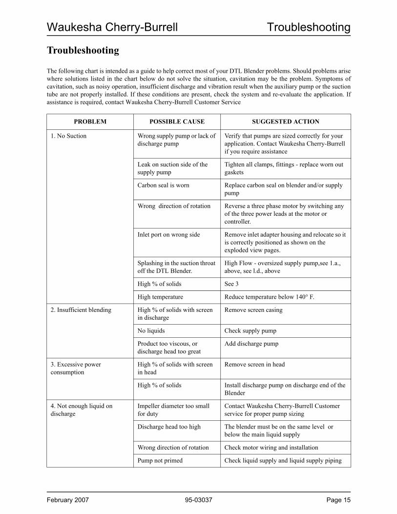
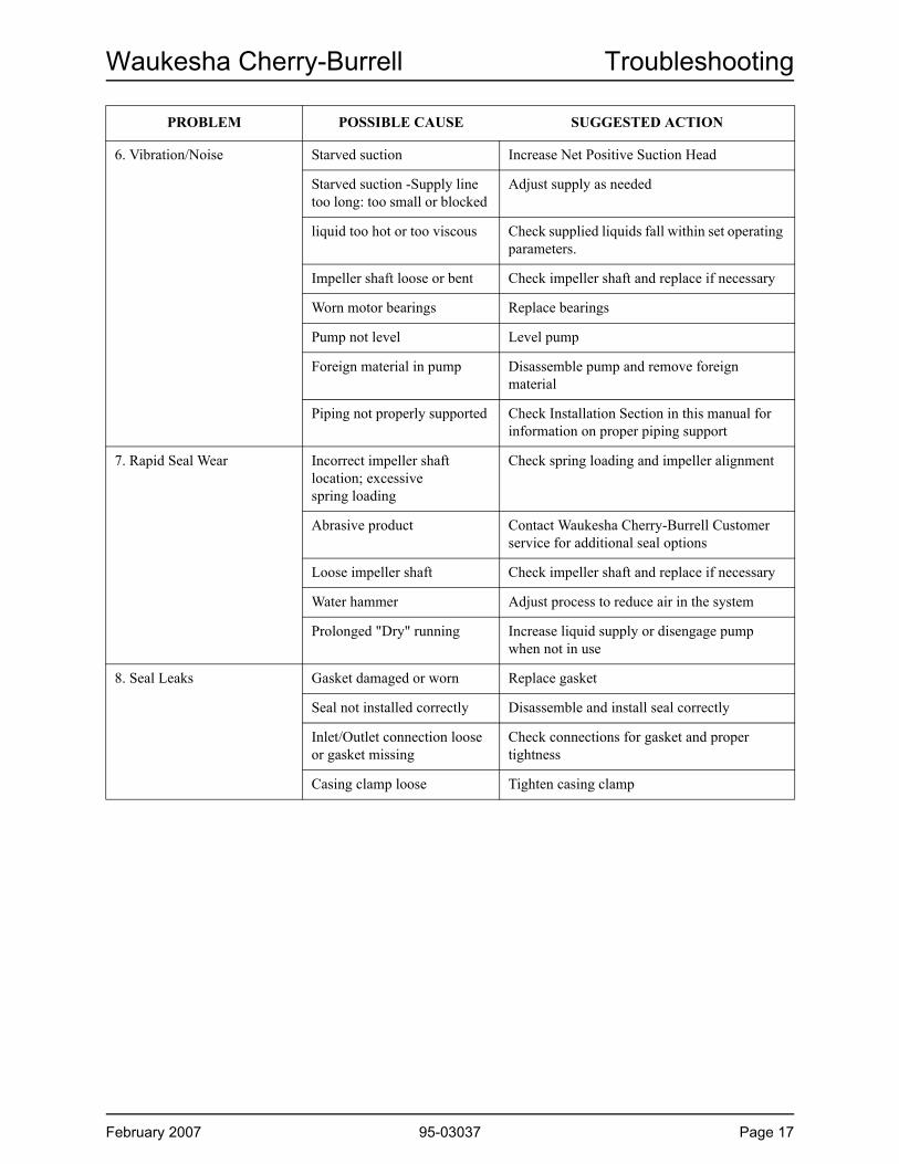
The following chart is intended as a guide to help correct most of your DTL Blender problems. Should problems arise where solutions listed in the chart below do not solve the situation, cavitation may be the problem. Symptoms of cavitation, such as noisy operation, insufficient discharge and vibration result when the auxiliary pump or the suction tube are not properly installed. If these conditions are present, check the system and re-evaluate the application. If assistance is required, contact Waukesha Cherry-Burrell Customer Service
PROBLEM POSSIBLE CAUSE SUGGESTED ACTION
1. No Suction Wrong supply pump or lack of discharge pump
Verify that pumps are sized correctly for your application. Contact Waukesha Cherry-Burrell if you require assistance
Leak on suction side of the supply pump
Tighten all clamps, fittings - replace worn out gaskets
Carbon seal is worn Replace carbon seal on blender and/or supply pump
Wrong direction of rotation Reverse a three phase motor by switching any of the three power leads at the motor or controller.
Inlet port on wrong side Remove inlet adapter housing and relocate so it is correctly positioned as shown on the exploded view pages.
Splashing in the suction throat off the DTL Blender.
High Flow - oversized supply pump,see 1.a., above, see l.d., above
High % of solids See 3
High temperature Reduce temperature below 140° F.
2. Insufficient blending High % of solids with screen in discharge
Remove screen casing
No liquids Check supply pump
Product too viscous, or discharge head too great
Add discharge pump
3. Excessive power consumption
High % of solids with screen in head
Remove screen in head
High % of solids Install discharge pump on discharge end of the Blender
4. Not enough liquid on discharge
Impeller diameter too small for duty
Contact Waukesha Cherry-Burrell Customer service for proper pump sizing
Discharge head too high The blender must be on the same level or below the main liquid supply
Wrong direction of rotation Check motor wiring and installation
Pump not primed Check liquid supply and liquid supply piping
February 2007 95-03037 Page 15
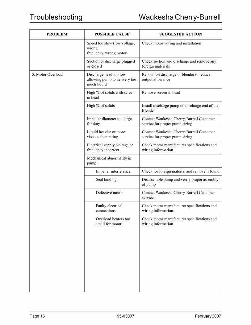
Troubleshooting Waukesha Cherry-Burrell
PROBLEM POSSIBLE CAUSE SUGGESTED ACTION
Speed too slow (low voltage, wrongfrequency, wrong motor
Check motor wiring and installation
Suction or discharge plugged or closed
Check suction and discharge and remove any foreign materials
5. Motor Overload Discharge head too low allowing pump to delivery too much liquid
Reposition discharge or blender to reduce output allowance
High % of solids with screen in head
Remove screen in head
High % of solids Install discharge pump on discharge end of the Blender
Impeller diameter too large for duty
Contact Waukesha Cherry-Burrell Customer service for proper pump sizing
Liquid heavier or more viscous than rating.
Contact Waukesha Cherry-Burrell Customer service for proper pump sizing
Electrical supply, voltage or frequency incorrect.
Check motor manufacturer specifications and wiring information.
Mechanical abnormality in pump:
Impeller interference Check for foreign material and remove if found
Seal binding Disassemble pump and verify proper assembly of pump
Defective motor. Contact Waukesha Cherry-Burrell Customer service
Faulty electrical connections.
Check motor manufacturer specifications and wiring information.
Overload heaters too small for motor.
Check motor manufacturer specifications and wiring information.
Page 16 95-03037 February 2007
Waukesha Cherry-Burrell Troubleshooting
PROBLEM POSSIBLE CAUSE SUGGESTED ACTION
6. Vibration/Noise Starved suction Increase Net Positive Suction Head
Starved suction -Supply line too long: too small or blocked
Adjust supply as needed
liquid too hot or too viscous Check supplied liquids fall within set operating parameters.
Impeller shaft loose or bent Check impeller shaft and replace if necessary
Worn motor bearings Replace bearings
Pump not level Level pump
Foreign material in pump Disassemble pump and remove foreign material
Piping not properly supported Check Installation Section in this manual for information on proper piping support
7. Rapid Seal Wear Incorrect impeller shaft location; excessivespring loading
Check spring loading and impeller alignment
Abrasive product Contact Waukesha Cherry-Burrell Customer service for additional seal options
Loose impeller shaft Check impeller shaft and replace if necessary
Water hammer Adjust process to reduce air in the system
Prolonged "Dry" running Increase liquid supply or disengage pump when not in use
8. Seal Leaks Gasket damaged or worn Replace gasket
Seal not installed correctly Disassemble and install seal correctly
Inlet/Outlet connection loose or gasket missing
Check connections for gasket and proper tightness
Casing clamp loose Tighten casing clamp
February 2007 95-03037 Page 17

Parts Lists Waukesha Cherry-Burrell
Puriti DTL Blender Model F2116MD
Page 18 95-03037 February 2007

Waukesha Cherry-Burrell Parts Lists
1 Hopper, 40 Degree 1 603061A Hopper, 60 Degree 1 603072 Butterfly Valve, Manual S-51 1 606854 Clamp 2 119-305 Gasket, BUNA 2" 2 20-36 Clamp 2 P119-2877 Gasket, BUNA 3" 2 20-58 Diffuser and Suction Tube 1 603099 Inlet Adapter, 3" x 1" 1 6031010 Casing, 1 6086811 Screen 1 6086912 Capscrew, Impeller, 18-8SS 1 30-15113 Washer, Impeller 1 6031414 Impeller 1 6031515 Casing Gasket 1 6010116 Backplate “D” 1 6031617 Pin, Backplate 2 6001318 Clamp, Casing 1 6008122 Ring Adapter 1 6032023 Pin, 3/16 x 2", Adapter 2 6063424 Carbon Seal 1 6008625 O-ring Seal, BUNA 1 N7021626 Cup 1 6008927 Spring 1 6009228 Stub Shaft 1 6086529 Setscrew, Stub Shaft 2 30-43630 Deflector 1 6086731 Spacer 6 6032432 Capscrew, Spacer 6 30-3033 Base 1 6032634 Capscrew, Motor, 18-8SS 4 30-10335 Lockwasher, 1/2", Motor 4 43-1636 Seal Guard 1 6032937 Motor C- Face, Standard 4 Poles 3 H.P. 1 211638 Leg, Adjustable 4 6061139 Drive Collar 1 60095R140 Setscrew, Drive Collar 2 30-17844 O-ring, Seal, BUNA 1 N70222
F2116MDNotes: 1. Complete Assembly
Puriti DTL Blender Model F2116MD
PART NO. NOTESITEM
NO. DESCRIPTION QTY
February 2007 95-03037 Page 19
Parts Lists Waukesha Cherry-Burrell
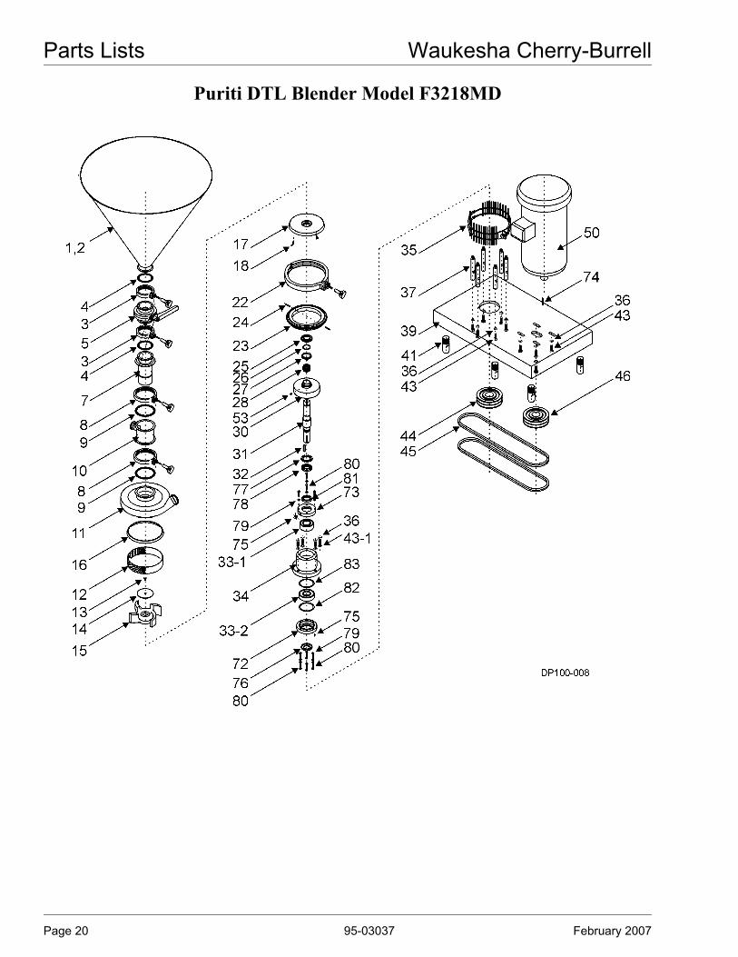
Puriti DTL Blender Model F3218MD
Page 20 95-03037 February 2007

Waukesha Cherry-Burrell Parts Lists
1 Hopper, 40 Degree 1 603432 Hopper, 60 Degree 1 603443 Clamp 2 119-344 Diffuser Gasket 2 20-5 5 Butterfly Valve, S-51 1 606867 Diffuser and Suction Tube 1 603468 Clamp 2 119-499 Adapter Gasket 2 20-6 10 Inlet Adapter Housing, 4" x 1-1/2" 1 6034711 Casing, 4" x 2" 1 6087012 Screen 1 6087113 Capscrew 1 30-65614 Washer, Impeller, Special 1 6035115 Impeller 1 6035216 Casing Gasket, BUNA 1 6010317 Backplate “D” 1 6035318 Pin, Backplate 2 6001322 Clamp 1 6008223 Adapter Ring 1 6035424 Pin, 3/16 x 2", Adapter 2 30-434 25 Carbon Seal 1 6008726 O-ring Seal, BUNA 1 N70222 27 Cup 1 6009028 Spring Seal 1 6009330 Collar Deflector 1 6035531 Shaft 1 6035632 Key Pulley/Shaft 1 60357
Bearing, Sealed 1 030036000 Bearing, Sealed 1 60358
34 Housing, Bearing 1 6035935 Seal Guard with capscrew and nut 1 60360 1
Lockwasher, 1/2", Housing Bearing 4 43-16Lockwasher, 1/2", Spacer 6 43-16Lockwasher, 1/2", Motor 4 43-16
37 Spacer 6 6036239 Blender Base 1 6036441 Leg, Adjustable 4 60330
F3218MDNotes: 1. Complete Assembly
36
NOTES
Puriti DTL Blender Model F3218MD
33
DESCRIPTIONITEM NO. QTY PART
NO.
February 2007 95-03037 Page 21

Parts Lists Waukesha Cherry-Burrell
Puriti DTL Blender Model F3218MD
Page 22 95-03037 February 2007

Waukesha Cherry-Burrell Parts Lists
Capscrew 6 30-103Capscrew 4 30-103Capscrew 4 60863
44 Pulley 1 30-12745 Drive Belt 2 6036746 Pulley 1 6036850 Motor 254TC 15 HP, 1700 RPM 1 321853 Setscrew 2 30-178 72 Posterior Plate 1 6060373 Interior Plate 1 6060474 Key Pulley/Motor 1 6070175 Greaser, 1/8" 2 BD009200176 Retainer Posterior, 13844 1 6060677 Star Washer 1 6060778 Safety Nut 1 6060879 Lockwasher, Retainer Backplates, 1/4" SS 10 43-2280 Capscrew 10 30-10281 Retainer Interior 1 6088382 Shim O.D. 3.5" Thick 0.005" * 6074483 Shim O.D. 3.5" Thick 0.010" * 60747
F3218MD2Notes: * Variable
43
ITEM NO.
Puriti DTL Blender Model F3218MD
DESCRIPTION QTY PART NO. NOTES
February 2007 95-03037 Page 23

Notes


S PX FLOW TECH NOLOGY
611 Sugar Creek Road
Delavan, WI 53115
P: (262) 728-1900 or (800) 252-5200
F: (262) 728-4904 or (800) 252-5012
SPX reserves the right to incorporate our latest design and material changes
without notice or obligation.
Design features, materials of construction and dimensional data, as described
in this bulletin, are provided for your information only and should not be relied
upon unless confirmed in writing.
Please contact your local sales representative for product availability in your
region. For more information visit www.spx.com.
The green “>” is a trademark of SPX Corporation, Inc.
ISSUED 02/2007
COPYRIGHT ©2013 SPX Corporation
DTL Blender