DTIC FILE COPY - Defense Technical Information · PDF fileUNCLASSIFIED DTIC FILE COPY...
44
UNCLASSIFIED DTIC FILE COPY SF-.URIT" Form Approved NTATION PAGE OMB No 0704.0188 Exp Date Jun30, 1986 a. REPno° AD-A223 479 1b. RESTRICTIVE MARKINGS 2a. SECt , , 3. DISTRIBUTION/AVAILABILITY OF REPORT Nnnp Approved for public 'release; distribution 2b. DECLASSIFICATION/DOWNGRAII i S,'!I I, is unlimited. None i 4 PERFORMING ORGANIZATION JUMBE n S. MONITORING ORGANIZATION RdPTABER(S) /$OSR.Tft 90 6a, NAME OF PERFORMING ORGANIZATION 6b. OFFICE SYMBOL 7a. NAME OF MONITORING ORGANIZATION University of Southern (If applicable) Department of the Air Force California Air Force Office of Scientific Research 6c. ADDRESS (City, State, and ZIPCode) 7b. ADDRESS(City, State, and ZIPCode) "6V2\\.41 Institute for Robotics & Intelligent Systems Bolling Air Force Base, D.C. 21, 2-6448 Powell Hall Room 204 Los Angeles, CA 90089-0273 Ba. NAME OF FUNDING/SPONSORING 8b. OFFICE SYMBOL 9. PROCUREMENT INSTRUMENT IDENTIFICATION NUMBER ORGANIZATION Air Force Office (if applicable) of Scientific Research Grant No. AFOSR-89-O032 8c. ADDRESS (City, State, and ZIP Code) 10. SOURCE OF FUNDING NUMBERS Building 410 PROGRAM PROJECT TASK IWORK UNIT Bolling AFB, D.C. 20332-6448 ELEMENT NO. NO. NO, ACCESSION NO S)56 A 11. TITLE (Include Security Classification) -. Parallel Architectures.'and Algorithms for Image Understanding Final Thchnical Report 12. PERSONAL AUTHOR(S) R. Nevatia and V.K. Prasanna-Kumar 13a. TYPE OF REPORT 113b. TIME COVERED 14. DATE OF REPORT (Year, Month, Day) 15. PAGE COUNT Final Technical Report FROM _I/I/88To 9/30/8g 1990, May 17 39 16. SUPPLEMENTARY NOTATION e 17. COSATI CODES 18. SUBJECT TERMS (Continue on reverse if necessary and identify by block number) FIELD GROUP SUB.GROUP/f" Parallel Architectures, Parallel Algorithms, Latin Squares, ma e Understan ing, Array Access. Processor Time Optima Solutions, Image Labelling, Low Level Vision. 19. ABSTRACT (Continue on reverse if ne essary and identify by block number) Several issues in using pa allel processing for image understanding are addressed. First, efficient schemes for para lel image array access are developed. New class of latin squares called perfect latin squar s are defined. Several construction methods are shown and some useful properties of such s uares are identified. A generic parallel model.. of computation employing electro optical d vices is developed. Parallel techniques for image computations are d.eveloped on this model. Finally, processor time optimal solutions to several low and intermediate level image und rstanding tasks are designed on orthogonal access parallel architectures. 20. DISTRIBUTION/AVAILABILITY OF ABSTRACT 21 ABSTRACT SECURITY CLASSIFICATION (n UNCLASSIFIED/UNLIMITED 0 SAME AS RPT. 0- DTIC USERS Unclassified 22a. NAME OF RESPONSIBLE INDIVIDUAL 22b TELEPHONE (Include Area Code) 22c OFFICE SYMBOL Abraham Waksman, Program Manager (202) 767-5025 IM DD FORM 1473, 84 MAR '83 APR edition may be used until exhausted SECURITY CLASSIFICATION OF THIS PAGE All other editions are obsolete Uncl ass i fied
Transcript of DTIC FILE COPY - Defense Technical Information · PDF fileUNCLASSIFIED DTIC FILE COPY...

UNCLASSIFIED DTIC FILE COPYSF-.URIT"
Form Approved
NTATION PAGE OMB No 0704.0188Exp Date Jun30, 1986
a. REPno° AD-A223 479 1b. RESTRICTIVE MARKINGS
2a. SECt , , 3. DISTRIBUTION/AVAILABILITY OF REPORT
Nnnp Approved for public 'release; distribution2b. DECLASSIFICATION/DOWNGRAII i S,'!I I, is unlimited.
None i4 PERFORMING ORGANIZATION JUMBE n S. MONITORING ORGANIZATION RdPTABER(S)
/$OSR.Tft 906a, NAME OF PERFORMING ORGANIZATION 6b. OFFICE SYMBOL 7a. NAME OF MONITORING ORGANIZATIONUniversity of Southern (If applicable) Department of the Air ForceCalifornia Air Force Office of Scientific Research
6c. ADDRESS (City, State, and ZIPCode) 7b. ADDRESS(City, State, and ZIPCode) "6V2\\.41Institute for Robotics & Intelligent Systems Bolling Air Force Base, D.C. 21, 2-6448Powell Hall Room 204Los Angeles, CA 90089-0273
Ba. NAME OF FUNDING/SPONSORING 8b. OFFICE SYMBOL 9. PROCUREMENT INSTRUMENT IDENTIFICATION NUMBERORGANIZATION Air Force Office (if applicable)
of Scientific Research Grant No. AFOSR-89-O0328c. ADDRESS (City, State, and ZIP Code) 10. SOURCE OF FUNDING NUMBERSBuilding 410 PROGRAM PROJECT TASK IWORK UNITBolling AFB, D.C. 20332-6448 ELEMENT NO. NO. NO, ACCESSION NO
S)56 A11. TITLE (Include Security Classification) -.
Parallel Architectures.'and Algorithms for Image UnderstandingFinal Thchnical Report
12. PERSONAL AUTHOR(S)R. Nevatia and V.K. Prasanna-Kumar
13a. TYPE OF REPORT 113b. TIME COVERED 14. DATE OF REPORT (Year, Month, Day) 15. PAGE COUNTFinal Technical Report FROM _I/I/88To 9/30/8g 1990, May 17 39
16. SUPPLEMENTARY NOTATION e
17. COSATI CODES 18. SUBJECT TERMS (Continue on reverse if necessary and identify by block number)FIELD GROUP SUB.GROUP/f" Parallel Architectures, Parallel Algorithms, Latin Squares,
ma e Understan ing, Array Access. Processor Time OptimaSolutions, Image Labelling, Low Level Vision.
19. ABSTRACT (Continue on reverse if ne essary and identify by block number)Several issues in using pa allel processing for image understanding are addressed. First,efficient schemes for para lel image array access are developed. New class of latin squarescalled perfect latin squar s are defined. Several construction methods are shown and someuseful properties of such s uares are identified. A generic parallel model.. of computationemploying electro optical d vices is developed. Parallel techniques for image computationsare d.eveloped on this model. Finally, processor time optimal solutions to several low andintermediate level image und rstanding tasks are designed on orthogonal access parallelarchitectures.
20. DISTRIBUTION/AVAILABILITY OF ABSTRACT 21 ABSTRACT SECURITY CLASSIFICATION
(n UNCLASSIFIED/UNLIMITED 0 SAME AS RPT. 0- DTIC USERS Unclassified22a. NAME OF RESPONSIBLE INDIVIDUAL 22b TELEPHONE (Include Area Code) 22c OFFICE SYMBOL
Abraham Waksman, Program Manager (202) 767-5025 IMDD FORM 1473, 84 MAR '83 APR edition may be used until exhausted SECURITY CLASSIFICATION OF THIS PAGE
All other editions are obsolete Uncl ass i fied

DISCLAIMER NOTICE
THIS DOCUMENT IS BEST
QUALITY AVAILABLE. THE COPY
FURNISHED TO DTIC CONTAINED
A SIGNIFICANT NUMBER OF
PAGES WHICH DO NOT
REPRODUCE LEGIBLY,

INSTITL 1IE IOR ROBOTICS ANI) IN FijI1,1GIN I 'YS I'MSI 1\*1 I%11 I (* 1 ,01 ," 11 IFTI: ( \1 I~ IN A t1
I'x vll I I 'all R moo 2i1)
1 )I - 4 1 i 377
OSRTR. , 0 06 75
May 1990
Dr. Abraham WaksmanProgram ManagerAFOSR/NMBuilding 410Boiling AFB, DC 20332-6448
Dear Dr. Waksman:
Please find enclosed six copies of our Final Technical Report for the period of November 1, 1988to September 30, 1989 on our AFOSR Grant #89-0032.
Sincerely,
,nciral Investigator
V.K. Prasanna-KumarCo-Principal Investigator
cc: Kathleen Wetherell, Contracting OfficerHarriet Vigoren, USC Contracts and Grants
encl: 6 copies of report
90 06 26 014

Parallel Architectures and Algorithms for ImageUnderstanding
AFOSR Grant # AFOSR-89-0032
Final Technical Report
R. Nevatia and V.K. Prasanna KuinarInstitute for Robotics and Intelligent Systems
University of Southern California
May 17, 1990
Accesioni For
NTIS CRA&iUric rAUiUard1,Ou1.ced 0
ByDistribtitio ij
-
O T I C
Avail jadljorDist soecial
1I

Summary of Results
This report describes the major accomplishments under the grant AFOSR-89-0032. The main focus of research was on two major areas: study of parallelarchitectures, and design of efficient parallel algorithms for image understand-ing. In the following, we summarize the research. The appendix includes copiesof publications supported under this grant.
1 Memory Systems for Image ProcessingI
Communication between memory and processors always has been a bottleneckin high performance computer systems. Low memory bandwidths can lead to asignificant performance degradation of these systems. Particularly, in real timeimage processing and vision applications, where the amount of data movementis enormous, very fast memory operations are needed. A new efficient memorysystem has been proposed for image processing and vision. In this system, LatinSquares are adopted as the skewing scheme. A new type of Latin squares, per-fect Latin squares with special properties are introduced for imagi-.processing.A simple construction method for perfect Latin squares is also sh6wn.'The re-sulting memory system provides access to various subsets of image data (rows,columns, diagonals, main subsouares etc.) without memory conflict. The mem-ory modules are fully utilized for most frequently used subsets of image data.The address generation can be performed in constant time. This memory systemis the first known system that achieves constant time access to rows, columns,diagonals and subarrays using minimum number of memory modules [5].
2 Electro-optical Architectures
Arrays of processors with optical interconnection networks for fine grain imageprocessing are studied. It has been shown that the unit time interconnectionmedium made possible with the use of free space optics results in efficient so-lutions to communication intensive image computations. Using these models,O(logN) pointer based algorithms for several tasks in low and medium levelvision are presented. We also presented a generic soldtion that can be usedto simulate PRAM algorithm for image computation on the proposed electro-optical arrays [4].
2

3 Orthogonal-access Parallel Organizations
We have investigated a class of orthogonal-access parallel organizations for ap-plications in image and vision analysis. These architectures consist of a mas-sive memory and reduced number of processors which access the shared mem-ory. The memory can be envisaged as an array of memory modules in thek-dimensional space, with each row of modules-along a certain dimension con-nected to one bus. Each processor has access to one bus along each dimension.It is shown that these organizations are communication-efficient and can provideprocessor-time optimal solutions to a wide class of image and vision problems.In the two dimensional case, tlhe basic organization has n processors and n x nmemory arr-', which can hold n x n image, and it provides 0(n) time'solution toseveral imat computations including: histogram, histogiam equalization, com-puting connected components, convexity problems, and pomputing distances,etc. [6].
3
References
[1] H.M. Alnuweiri, and V.K. Prasanna Kumar, Fast Image Labeling Using Lo-cal Operators on Mesh-Connected Computers, Proceedings of InternationalConference on Parallel Processing (ICPP), 1989.
[2] H.M. Alnuweiri, Communication efficient Parallel Architectures and Algo-rithms for Image Computations, Ph.D. thesis, August 1989, USC.
[3] M. Mary Eshaghian Parallel Computing Using Optical InterconnectionNetworks, Ph.D. thesis, Decelber 1988, USC.
[4] M. Mary Eshaghian and V.K. Prasanna Kumar, Fine Grain Image Com-putations on Electro-optical Arrays, Proceedings of IEEE conference onComputer Vision and Pattern Recognition (CVPR), 1989.
[5] Kichul Kim and V.K. Prasanna Kumar, Parallel Memory Systems for Im-age Processing, ProceeAings of IEEE conference on Computer Visitun andPattern Recognition ((U, ,rPR), 1989.
[6] V.K. Prasanna-Kumar, Parallel Image Computations on Reduced VLSI Ar-rays, Indo-US Workshop on high speed signal processing, 1989.
4

Appendix
Appears in Proceedings of the IEEE ComputerVision and Pattern Recognition Conference,1989.
Parallel Memory Systems for Image Processing i
KIichul Kiut mid V. K. Irasamia Kuniar
)Dvartllwiet orf IBlectl'ieal EI*gilleerilig-,S'ysten.
i~s
University of Southerni ,aliforina
Los Aigeles, CA )0089-0781(2!3).7,13:.523(;
The effective )an(Iwidt h of t helse nie|||ory systems not onlyAbstract depceilds on the number of modules and the speed of oper-
ation but also depends on the occurreuice of mnemory con-A novel memory system is proposed for image process. flicts, which occur when more than one memory request ising. Latin squares, which are well known combinatorial given to the same memory module during a memory cy-objects for centuries, are used as the skew function of the cle. Hence, the memory system should provide conflict freememory system. We introduce a new Latin square with access to as many subsets Qf interest as possible.desired properties for image array access. The resulting Many rese.rchers Jiave addressed the issue of design-memory system provides access to various subsets of im- ing memory systems which provide efficient access to rows,age data(rows, columns, diagonals, main subsquares etc.) columns, diagohals or subarraysl,2,9,11,12,16,17,18,19].without memory conflict. The memory modules are fully Budnik and Kuck introduced linear skewing scheme andutilized for most frequently used subsets of image data. prime memory system which allows conflict free access toThe address generation can be performed in constant time. rows, columns, diagonals and N1/2 x N112 subarrays of anThis memory system is the first known memory system that N x N array, in which the number of memory modules is aachieves constant time access to rows, columns, diagonals prime number greater'than N12,91. However, their methodand subarrays using minimum iumber of memory modules. needs modulo operation ok.a prime number in address gen-
eration, which can not be performed in constant time withI Introduction a reasonable amount of c}jcuitry. Lawrieill generalized
the linear skewing schieme'and proposed an array storageWith recent advances in VLSI and parallel processing, large scheme with a simple address generation. His scheme pro-Wither opreavcesrs in VbS atparllelt proeig arge vides conflict free access to rows, columns, diagonals andnumber of processors can be iptercosnected to yield high N" 2 x NO/ subarrays of an N x N array using 2N memoryperformance systems for image processing and vision. ost modules. lie also introduced the omega network to perform
tations but also process enormous a ount of data. Low data routing aid data alignment. However, his scheme suf-
effective bandwidth of the memory system can lead to sig- fers from low utilization of nemory modules. Only half of
nificant performance (legradaio|n. Inm order to fully utilize the memory modules are used in a ncmnory fetch. Men-
the processing power available in parallel systems, special ory organizations with linear skewing schemes suffer either
attention should be given to memory organiizations as well low memory utilization or difficulty in address generation.Another way of achieving ellicieit access to various subsetsas mapping of image arrays, of interest is by using nonlinear skewing schiemcsll,3,12,161.
In image processing, an imnage can be relnleselited by a
two dimensional array of size ,I x N. It is well understood Lee[12] presented a nonlinear skewing sclenme(called scram-bled storage scheme) and a new network which allows con-that access to row vectors, cohuim vectors, diagomials amid fitfe cest os ounsur lcsails
subarrays are required heavily in iniage I)rocessing{10,17]. flict free access to rows, columns. square blocks an(! lis-
A memory system for inage piocessing should )rovi(le ef- tributed blocks. The scrambled storage scheme does notiieedl modulo operations for a(lrcss generation. However,ficent access to rows, coluums, (liagonmls amid subarrays. it can inot plrOVide elliciiut access to diagomialds.
Also, while implement iig partilioed VI.SI arrays and spe- i vcn t pgi a h ,t as i tiatnl im
cial purpose arrays, access to various ubatkrays is ineedled. lven thgh a hot or wok has been done in the con-
'lodlay's comiputters use immilt ' tumcmiory modules eit her text of array storage sclimies for ge,,eral purl)ose parallel
in interleaved meimorv forimi or in, IalM nIniillory foric. Coniputers, not inuh has been l done with re.pect to accesspatterns needed for image pro cessinmg and visioni. \oorhis
'This research was supliorid In pail tit ' : ms..,.,I el R-1iil- atid Morriil 171 pto(.(sed a linar skewing schelme and andation under grant tItI-S71iOs:$t antd iiit l, Al-(i1It widr griant address getirat ion circuit mr*v for image prcesiig ini whichAFOSR-89-032. (illy olle imemtory umillihle 6 i, u.sed I duting a inemiiory
654CH27524/89/0000/0654$01.00 (c 1989 IEEE

itltidlo mI't .ii til with .1ati'' ~'i'ij inot .1 power (of I oli't.,~ 611 111 ~ie avie for athit riry data; avcst'c,'n
li ilii't oll Ii I'. veat'55 I 0 ''ttjioltt I ofd tIt a. itiiry schemtie call lbe pride~tcd fotr act'ts to t the siilin.tswei pt ipom. to ose Lat iti stqitare; which are well knouwni cook of ititet s'it lehiltitg ill hligh effective liatiuwi(lt It.in tat 'i ia! iiijet' I ftr ct ent iirit'sj'l j. We intro ducte a tiew Ilkiittin 1ge gir ces',iotg. row verfors, t'iili t iVetoris. sit il
La;i militat(dltted pel~fect Lat itt sqiare) whtichl has p l -iat taysatid ufi-igtitals(uir dliagontals of suliari'ays) are hevavily,'rtjes itsefit for itt ag' 'ess i anit Vil i. We' uLIst show l*lm lit' h importain't' of row access is ohbviouts ciii si dtriiiI %it itje cotnstrutio mttnethod! for' perfect ILat in sqitat es. U.". thiat itai ilt. ip its anitd out puts *,re usually itt tow mtajor
ig peifet' La tin squtiarit as t he skewing schet ne, various sub. ord er( left toi right , loip to hottotm). '[here are also t t aitsets of ini age data a ir accessible withlouit memtiory con flict a Igori t Ii is whli ch nteed row accesses like one iitntsionialwhile inc tmtry tmiod~ule s are fully uttil ized for most intecrest- con voluition alIgori thmis. D~esirability3 for colutin access isitig subsets of imnage data. Furthermiore, it is possible to justifiedt 1'y thle commonly used 90 degree rotation of inmageshow that t'e address generationi call be donie in cotnstant and by adgorit lims which nteed column accesses like the twottime'. tdi tiut'siotual L7TT algorithms. Subarrays play ati itlpor.
lin the tiext sectioti. we tdescribe memory access require- tant role in two dimnsionial (emplate matching amid othermnetts for image processing. lit section 3, we introduce p~er. algorit huts. P'artit ionuing is all essenitial step ii imap~pingfect Latini squares. We also show a construction method for algorithiuis to fixed size VLI arraysjl31. Access to sub).perfect Lat in squares. lIn section 4, we describe how perfect arrays of imiage data is n~eeded in such implemetntationis.Latin squares call lbe used for storinig and retrieving imiage D~iagonials or (!iagotils of subarrays are also useful in mna.d!at a. Sectitin 5i conicludes the paper. t rix comnputat ion which is anl indispensable tool in image
processinlo)10.Frot the above argutnqts, it is obvious that a nmetmory
2 Preliminaries system for imuage processing should provide efficient, hope.
A meorymodle an e caraccried y te aoun of fully cotnflict free, access to row vectors, column vectors,A nimor moulecan e caraterzed y te aoun of subarrays, and diagonals for ipiage processing.
datat it can stcre and thc cycle time which is the fiii In% this paper, we restrictour attenution to the casesmnum timue betweent two consecutive read or write oper- where the tnumiber of mietorx modules is an even poweratiotis. Clearly, the cycle time determinies bandwidth of of t wo. rhe desirability of ha'iiug puniber of memory mod-the memory system. To ov'ercomne the linmitatiotn imposed uetobanvnpwrofwoiclrinersfaddress
by ccletim, inihile emor moule areuse It t0 getneration, utilization of address space and interconnectionday's computers. One way of using nmultiple memory mod- niet work.tiles is by o~rganiizinig them as p~arallel memory banks. itthis inemory system, multiple mnemory baniks are accessedat the same time, therefore, the effective memory band- 3 Latin Squares for M emory Ac-with is multiplied by the number of memory baniks. This cessscheme is commonly usedl in SIMD or MIMD computers.Anmot her way of using multiple memory modules is by orga- A\ JLfn tquotrc of ordler it is anl it x n square compiloseditizitig t hem as initerleaved memories which are commuonly ut itlIt symibols from 0 to nt - I such that no symibol appearsemuployedl in pipelitied vector computers. lin this memory mnore than onice in a row or in a column[4j. The rows aresystetn, memory access mnechanismu is div~ided into several nmbeilrt'd fronm 0 to t - 1, top to bottomn. The columins arestages and used itt a lpipelined mnattier. Cray X-Mll uses also numbercd front 0 to it - 1, left to right. The square Aa 32-way' interleaved tmemory system. Some memiory 53's' shown below is alt example of Latin square of order 'I.tets employ hot h parallel memory batiks atid ititerleavctlMlemnories. lit such a system, each parallel memory batik is0123cot tposcil of inmte rleaved memories. 1I 2 3 0
E'veni if tmult illt imemor' mnodutle's are use1 d to intc rease2301ie( eff'ec'tivye band with of thle tmetnory syst etm, mem' tory 3011
'otficlt t'ati greatly retdtce the effective batdidtth. 'or A dingiinsi Ihulini sqtwt'c of order ii is a Latini stquare stichatit extit 't te t's atit td, if all that a eci ien ts to be accessetd mt ' that not symtblol appears inore thant oitc' in any of its twositi'd itt thelit' s ti nttiiry mtodutle, tilie e' ft'ttivi' bauwtii itl I Ii i i diagotials. A sitmtple conistructio mu thod is kntownits s i tilt' a" m .ii on~t tly onte inint ory tittdutll' i rrespect ivt' of G- r di agotsial Latint squares of order im whtenti is aI power'
of m wo'l1 ( i'rgelv l wed a getn't'al it'l sto to .'ottstrnit t
655

diag a o , s v.a .of "-my t " 17 ..'1 .,l1are1 , I 3.lI it ii , n3 1.. I I..,, 1,, b' ..ri I,. fb,11hy m if. 3331 l.,tolinsilwn hihelow is an exaph. ih'f ,i .l I.at in -.,I llar o ICif l.r m/11111l .1 o ort iA Il I of oid( r it. thcn ther( t tists itI. 313103doub li .j, If.,'lhohi,.ml L.am mit, rt ( of o 1/ , r 33i..
3 " 1 Proof. 1: lom ilie diiily m.lf(t hlogt al Latin squat es .S:1 ' 2 'and B i, we c.1onl aI mlimic (i f .rl1'r in willi tit. f,.-I (1 :} ; J I(wilig rule:
Iwo Latin squ ares C I I ) of , .i dei Ii ,ire (i whoyona Itoeach other if I lite wt of or(d ered pairs V,, u ' . , i ,, . .. , < ij " 12 -CD {(c, ,d,.,), 0 -. t.j ".i I} Is equal ;o t lie .etof all possible ordered Ipairs i,) ), (I -. i,j it - 1. The where [i/li) rel)resetits tite largest ittleger not exceeding i/nsquares C and D shown below are (rthogonal to each or. and i mod n represents the nonnegalive remainder of i/n.ther. rie construction of C can be viewed as follows:
C = 1 2 0 2 1. Construct a -. tiare of order inn using tin Bi's. Let12 0B,. be the square I.whose position is i + 1 from top
A self.orthogonal Latin square is a Latin square orthogonal and j + I from left.
to its transpose. We define a doubly sclf.orlhoyonal Latin 2. Add is x a, to all i ncbers of ,,,.square as a Latin square orthogonal to its transpose and1to its antitranspose. Notice that a doubly self.orthogonal An exanl)le is shown below for the case m = it = 22.Latin square is also a diagonal Latin square. The square B 0 3shown above is also an example of doubly self.orthogonal 2 3Latin square. We define a subsquarc S,., of a Latin square 0of order n2 as an it x n square whose top left cell has the 3 2 1 0coordinate (ij). When i -- 0 mod 13 and j = 0 mod it, the 1 0 3 2
subsquare S.j. is called a mailn..subsquarc. Subsquare S0, 0 1 2 3 4 5 6 ,7 8 9 10 11 12 13 14 .
of the square B is [ 2 1 and main subsquare S.20 of the 2 3 0 1 6 7 4 '5 10 11 8 9 14 1512 13r 3 0 3 2 1 0 7 6 5 4 I1 10 9 8 15 14 13 12
1 3 2 5 4 7 , 9 8 11 10 13 12 15 143$ 20 11 12 13 14 15 0, 1 2 3 4 5 6 7square B is We define a pcrfcct Latin squarc of 10 II 8 9 1.4 15 12 13 2 3 0 1 6 7 4 5I 0 II 10 9 8 15 II 13 12 3 2 1 0 7 6 5 4
order n2 as a diagonal Latin square of order n2 such that 9 R It 10 13 12 15 1.1 1 0 3 2 5 ,4 7 6no symbol appears more titan once in any main subsquare. 12 13 14 15 8 9 10 I .1 5 6 7 0 1 2 3
14 15 12 13 10 11 8 9 6 7 4 5 2 3 0 1Hence, in a perfect Latin square, no symbol appears more I114 13 12 II t0 9 8 7 6 5 4 3 2 I 0than once in aniy row, in any column, in any diagonal or 13 12 15 14 9 8 10 It 5 4 7 6 I 0 3 2in any main subsquare. Tile square E shown below is a 4 5 6 7 0 I 2 3 12 13 14 15 8 9 10 11perfect Latin square of order 9. 6 7 4 5 2 3 0 1 14 15 12 13 8 9
7 6 5 4 3 2 1 0 15 14 13 12 9 80 3 6 1 1 7 2 "5 $ 5 4 7 6 1 0 3 2 1 3 1215 14 9 11 102 5 8 0 3 6 1 4 7 C1 4 7 2 5 8 0 3 6
7 From the construction, it is clear that no symbol appears
E 5 8 l 3 6 01.1 7 1 more than once in any row or in any column. Suppose4 7 1 5 8 2 3 6 0 C is not orthogonal to its transpose. rhere should exist6 0 3 7 1 1 8 "2 i,j,k atd 1, i I k or j .z? 1, such that c,, ck, an(8 2 5 6 0 3 7 1 , C,., =0c:. Sce 0_<n,,q< i-1, 0_p,q < -1, and7 1 .1 8 2 5 i 0 3 O b,.,<it- 1,0< r,s < l. fromc,., =c.1, we have
In the rest of this section, we presetit a construction "i,/,l,, n a },.ltn (Imethod for perfect Latin squares of order ,,2 for the casei 2 is, k (1.2,3 ... ). The it rested l(ader can refer " .. .... I n = b , ,,,t. ,dn (2)
to [81 for the construction of perfect I,atin mluares of order From c., - ClI. we haven2 where it is o d d( r it -2in', 1 ( (2.3. 4.... }.m is odd.
For the construction of perfect Ilatill sqiares. we start 'l~l,,I.f)/. n) ,l,,l (p)wil] the following h',luiia. , . ,,, . , (.1)
656
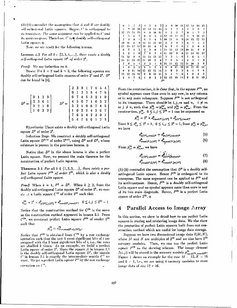
.1111~~~~~ ~ ~ ~ ~ ~ i.1 IitIIwasliII)ItIII I ha 4 I II It 8 I BI are t2lYI ? 3 1 N 6 7 9 11 1 2 1 3
Latlill squle . Elt It 1 9 141 1!, 12 13t 2 .1 0 1 1) 7 -1 I
No~w. we are ready fot tit( followinig lemlnni. I !. I13 10 1 t 1.9 6 7 4 5 2 31 0 1C 7 4 , 2 3 0I 1 11 1 . 12 13 10I 11 $ 9I
Leina ;.2 lPor till k k- (2, 3,4l,... lhcrr exists a dlublt 3 2. 1 II 14F C. 5 I1 It 11I) 9 8 15 -14 13 12
MVlfort1loqonail Latin square Wk of oridcr 24. F. 1t1 1: Is t1 10i 9~ S:i6t 2 1 0 ~CI I " 2 1 0 1S 111 13 12 11 1II 9 8
lProof: We Ilse indtlion tolOil k. i If J 2 -5- 4 4 I10 13-T iV2 It. 1Blases: F-r k =.2 and k -%3, tlite following squares are 9 8 It t0 13 11 15 141 1 0 3 2 5 4 7 6
dloub~ly self-ortliogonal latin squares of order 22 and 2 3. 1) 13 12 15 14 9 8 1 0 II1 5 -1 7 6 1 0 3 2il 5 * 7 6 1 0) 3 2 13 2 IS 1 9 8 11 10
2 3 0 1 7 6 5 4 Front tile const rucetion, it is clear that, in tiw squnare Pit, no0 1 2 3 5 4 7 6 symblol applears m~ore than once in any row, in any column
012 36 7 4 5 3 2 1 0 or in any main subsquare. Suppose P"k is not orthogonal
L2 230 1 ' 45 6 7 1 0 3 2 to its transp~ose. There should-be i,in and n, i 0 rnor 0t 6uc 74a 5~ it' and pj' =P",. Fromn the
2j 32 56 ~' construtmn, p,0 5 i~j :5 2" - 1 can be expressed as
7lo 6 5~ 4~ 6 0 0 1 2k =ic .)k~d I~=pk
1ypthesis: T1here exists a doubly self-orthogonial Latin we have 1 ,: '-1 rn '
Square D4 of order 2k. dk2lmo2 dk(5lInductionl Step: We construct a (doubly self-ortllogotial i/kjodh7lm/2'l.,n.d2&
Latin square D"" of order 2 '+2, using D 2 and Dk, Whose d md&tI& - dk,~&ri& (6)existence is proven in the previous lernina. a Frot p,* = we av
Notice that D 2 ill the above lemmia is also a pcrfcctkLatin square. Now, we presenlt the miain thleorem for thle dt.,I2 kj,imod2" d(6/2&p,.m.d2- (7)construction of perfect .tin squares. dirno2 k1 i 2 41 = (8
Theorem 3.1 For all ki E {1,2,3,.. .), thcrcexcists a per-. F)-S contradict the assumption that D' is a doubly self-fccd Latin square P"k of order 2 2k, which is (a1s0 a doubly orthogonal Latin square. Hence Plk is orthlogonlal to its.clf-orthoyonal Latin square. tranlspose. The samne argument can be applied to p2k and
Proof. Mwn k =1, 1" = D2 When k : 2, fromn the its anti transpose, Hence, p2k is a doubly self.-orthlogon al
doubly self-ortliogontal Latin square D A of order 2k, we con Latin square and 110 symbol appears more than once in any
s... dt a Latinl square C"k of order 2 - suchl tltat of its two mail (diagonals. Hence, plk is a perfect Latin
square of order 2 ". a
Notice that the conistruiction in litod for C2' is the samne 4 Parallel Access to Image A-rrayats the construction method appeared iti lelnlna 3.1. From [in this section, we sho0w in detail how to use perfect Latin(,2k, we construct perfect Latin square P"k of oretler 2 2' sq'uares in soigand rereigituageda. ealosw
sctht 2k *2k thle p~roperties of plerfect Latin squares built, fromt our con-lo, L2& Ytrmd2'+i/2Ily) strlictioll nlctilod which~ are useful for iniage (data storage.
Notic tht 2~ s htalel ro h)2k Uy row CXClIuIage Suppose we hlave two dimnsional inmage (1at 2kA, )operation, suchI I lhat the irst k 111(1st sigifiicanlt bits of i nrc whlere .I 11 and N are miultiples of 2 2k and we also have 2 kswappled with Ii le k- least signlificanlt bits of i, i.e., lite rows
are ilufled I ineS As ii ealiliewe bild perect illory Modules. Thieni, we canl use Lte perfect Latin
La.t in squlare of order 2'. Si ice lthe square A int Iciinna 3. 1 s~ae,2 stleseigshle 'ihneee eis Ilie doiil ly self-oil logoiial Lati n squIIare W), iii' tilnt ri x lI z. j)will be stored in tile IIinvilry modu1 le 1,& md.)C it, h-iuina :,.1I is exactly lte iilt'rilediate ina~trix C' we Figuie I shows ;it e'xamlple for the case Ul . 1'2,i N 16wa ial. We gvl a pe-rfect L a till sq Iire P' by I liv row vxci angt aniid k - 1, i.e., we arc uising -1 iiiei ory ill(11 ties to store
41i14-at iol I'll C( . imtage data of size 1*2 - 16.
657

which .siiit' Iint lIIIv itnt1IIIItIIIII 111-1.4 lof ntcintt0rv VI'll
0I 1 :t 2 0 1 :1 (1 II32( i sIw'wnii~n nii ~i ni'mih is ~~sci2 :1 1 2 :1 1 0 2 :1 1 0I 2 :
1 2 :1 1 0 2 3 1 21 :1 : I () 21 :t Lld illati 4.2 V\ tymthio! itppt ls a P n arft ti t Iti -t hina t i it, p
:1 2 0 1 31 2 0 1 3 2 0I 1 : '2 (1 fity crilosquintS,o 3 2 I I 2 II I 3 2 0I 1 3 2
2 3 1 0 2 31 1 11 2 1 1 (I 2 :3 1 () Leit ItIIM -1.2 is -I di rectI tcsulI of leitlI tit.1e~ lw~;tis everv
1 0t 2 31 1 0 2 31 1 0 2 : 1 0I 2 , sil ',(ttate Cal be partitione~d into tw a htt such thlat euach3 2 0 1 3t 2 0I I 3 2 0I 1 31 2 (1 1 (of tietni hclottg to I subsqttare onl ; strip (of with 2'.0 1 . 2 0I 1 3 2 0 1 31 2 0I 1 3 2 A nothler stubset of po,;sii)le in terest in imitage processing2 3 1 0I 2 :1 1 0I 2 :t 1 0I 2 1 1 (0 is tine sutbiset of eem ents whIose cootrdlinates are t-ie sal te1 0I 2 3 1 0I 2 3 1 0I 2 :1 1 0l 2 :1 wit Itin .each nuain stnbsquare. Th'lis su bset can be used[ ill31 2 0 I 31 2 0 1 3 2 0 1 1 -2 t0 1I algori thmis wic it ied a valute witini eachtn iti suibarray.
Let a1 sali position SI',j of a p~erfect Lat in square .A of
Figure 1: Mcniory assigntmient of 12 x 16 array tinto -1 mei ordler n2* be defined its follows,ory mtodul. SP., j I k Isi mod1 nt,1 Pj itmod t), 0 S i~j -1 .
Now, we have t h6 following lenitim which shows tio tnemiorycontflict occurs when a same ponsitiont is accessedi.
lin figure 1, it is easy to see that every I x 4I rows attd Lemma 4.3 No synibol appcnnrs ,,tre thman ontcr in anty
every 4 x 1 columns are accessible without mennotry con- .in position $P,flict. 2 x 2 mtaini subarrays are also accessible withoutmemory conflict. Data ott tlnc diagonals of -1 x '1 perfect 5 Conclusion*Latin squares are also accessible withot n enory conflict.These properties come directly from the definitioni of per- A new efficienut memory systcntn for image processitg atidfect Latini squares. However, figure I (Ices not fully demion- vision is described in thtis payer. Latin squares have beenstrate the properties of the perfect Latin squares built frotm adaptcd as thle skewing scIhen'4. 'Rerfect Lat in squares whichour construction method, because we are using, as the skew. tire Latin squares with special p~roperties uisefutl for imageing scheme, P2 whtich is not built front otir method. The processitng have ben introdutcedi. A sinmple constructionperfect Latin squares built from our construction met hod method for perfect Latitn squares is also shown. Uising per-(p'*k & > 2) have other properties which are very useful in fect Lautini squares as tine skewing scheme, inaity interestinigimage processing. It is easy to verify thme following property subsets(rows, columins, diagonals, mainu subarravs etc.) ofsatisfied by perfect Latin square of order 22Pr, k >: 2, built innuage data can be accessed withIout ituory confhlict.from theorem 3.1. lii this inenuory system, it is p)ossible to show t hat thle
Lemna4. Nosybo apcas noe tanorcc n sb. add~ress genterationi is v'ery easy for bztli muemory tmodu tleLem m S i hta t 4. =o sy b 0apa mo - ti an 0 nc i i n 2'. address antd local address wit hint muemuory mtoduiles. Mein-
squar S,, suc tha i 0mod 2 Om-j 0 tto~ 2k ry mtodlule address cant lbe geiierat ed in conist ant lttle withI
The above lemmna shows that not onlty Itle niit sl)- at simle logic circuitry andc local address generat in oessquresareaccssilewitoutineorycoflit bt aso v. not nieedl anty additionail hardware.
er usquares re tcesibe weih o i horzonalitritt o width'The efficient skewing sclenie along with lthle fast ;ddrecss
cry sar se a resi one ithou v ec lory corficotta. ti s o it generation circuitry nm akes it 1)0. ble tha~t rows. columtns.
Ik ar eacsy s e wthot mhe r o ntheict (ai s u r iagoinals, samne p~ositionts, and snbarrays caii be accessedIt i eas tosee hat her doe no exit a ati sqire , constanit time. This inenmiry systeimt achieves Ithis goal
such that no symbol appears more thn ontce in any sub. ingunni umeofeiry odlssquare, which means there is ito skewitng schtemte which uii niintniuie fimioymtdhs
gurnte cnlitfreacesto rows, coliumtns anid N1I2 X TRa I shows several1 kniownt itnemory sclmeittes alotig-NO1 subarrayswe emr ues~v ar Rie os i ith Ifile sc met ie proposed inn Ithis paperI. Compjarisonts arie
~ whn N uenoru'inodb.- areusedto tore hbased ott storinrg N x S dhitai. A\ i addreiss generttnt is
coiistlrct to lbe hard if it reqiuires iiotiuilo uoperatiituits of aintinl er wchich is inot, ;I power (If t wo,.
658

[ leslt' 1 ~of sig~,t ~ 1 .dlr~s II'.Y.10 ''1. I'SI Arity I'11 ~.I t ,. I.111.11 14-%'tiit' supported [ftiti j generat it'll 9~
- N diagonlal. linear hlard II. I). II. l,a.wrie. ".\tcv, and Alig titn.io of li)ta in :-,isuharray .,A "rtay I: v ,.o./ir." 1 "'ll.i.. ( o i , . ,,I .. (- 24,.row, coltut . I'P. I 1l;-I 1,5,. 197:'1,
fil N digottal, liiW44i easyI\iharraa -12j I). Ive. "Scra,,iled Storage fil I'irallel Mvi'ty Sv.-
'-'- --'v -- -1 row, columi linear I hardI i'thIl. Symp. Com, cr ..Irchit (clii, pp. 232-
sularray m2:). 19SS.
row, '131 .1. X. Navarro, .1. M. I laberia atd hi. Valeto, "Parti.121 I' column, nonlinear easy It ing: an essential step it) allappi g algortil s into
blocks I systolic array processors," IEEE (oiputcr, pp. 77-89,row, column, July 1987.
This N diagonal, nonlinear easypaper suharray '141 J. W. Park, "An Ellicient Memory Systemt for Image
same position_ n Processing," IEEE Trans. Conmput., vol. C-35, pp. 669-
Table 1: Comparison of memory systems (Blocks include 6.4, 1986.
square blocks and distributed blocks. Square blocks are [151 A. Rosenfeld and A. Kak. Digital Imnage iProces.king,same as main subsquares and distributed blocks are same Academic Press, 1976,.as same positions discussed in this paper.) i!6j II. 1). Shapiro, "Theoretical Linitations on the Effi-
cient Use of Parallel Memories," IEEE Trans. Cont.put.. vol. C-27. pp. .121-428, 1978.
References i171 D. C. V. Voorhis and T. It. Morrin, "Memory Systemsfor Image Proccssing,"'IEEE Trains. CompuL., vol. C-
III M. Balakrishnan, R. J'ain and C. S. Raghavendra, "On 27, pp. 113-125, 1978..Array Storage For Conflict-Free Memory Access For 1181 If. A. G. Wijshoff and J. V. Lecuwen, "The StructureParallel Processors," Proc. Intl. Con Parallel Pro. of Periodic Storage SchefAies for Parallel Memories,"cessing, vol. 1, pp. 103-107, 1988. IEEE Trans. Comput., vol. C-34, pp. 501-505, 1985.
12) P. Budnik and D. J. Kuck, "The Organization and Use 1191 If. A. G. Wijshoff and-J ". 'V. Leruwen, "On Lin-of Parallel Memories," IEEE Trans. Coinpul., vol. C- ear Skewing Schemes and d-Ordered Vectors," IEEE20, pp. 1566-1509, 1971. Trans. 'omput., vol. C-36, pp. 233-239, 1987.
131 A. Deb. "Conflict-free Access of Arrays-A counter Ex-ample,' Inf. Proc. Letters, vol. 10, No. 1, pp. 20, 1980.
141 J. Denes and A. D. Keedwell, Latin Squarcs and TheirApplications, Academic Press, New York, 1974.
151 E. Gergely, "A Simple Method for Constructing Dou-bly Diagonalized Latin Squares," J. CombinatorialTheory,, A 16, pp. 266-272, 1974.
161 A. lledayat, "A Complete Solution to the Existenceand Nonexistence of Knut Vik )esigns and OrthogonalKnut Vik Designs," J. Combinatorial Theory, A 22,pp. 331-337, 1977.
171 K. Ilwang and F. A. Briggs, Computcr Architecture4111( Parallel Prorcessing, McGraw-llill, 1984.
181 K. Kim and V. K. Irasanna Kumar, "Perfect LatinSquares and Parallel Array Access," Techn|ical ReportIRIS -.-239, Utiversity of Southern California, 1988.
{9( I). .1. Kuck, "II IAC IV Software a,,d ApplicationProgramming." IEEE "litrans. Coinjut., vol. C-17, pp.T5$-770, 1968.
659

7Y'-- -7
Appears in Proceedings of the' IEEEComputer Vision and Pattern RecognitionConference, 1989.
Fine Grain iImagc Computations oil Electro-opta, cal Arrays*
M. Mary Eshaghian and V. K. Prasanna-IKumar)epartment of Electrical Engineering-Systenis
University of Southern CaliforniaLos Angeles, CA 90089-0781
Abstract electronic interconnects is not possible unless one al-lows unbounded fan-in and or fan-out for each of the
In this paper, we consider a set of array proces- processors. In fact , a lower bound on the time tosors with optical interconnection networks for fine simulate one step of a PRAM on any bounded de-grain image processing. The unit time interconnec- gree network of N nodes using electrical intercon-tion medium made possible with the use of free space nects is fl(log N). Even though several networks haveoptics, results in efficient solutions to communication been designed to eflicienfly simulate PRAM (7], manyintensive image computations. Using these models, cost/performance issues limit their potential applica-we present a summary of our results in designing tion in high perTormance parallel systems.O(Iog N) pointer based algorithms 'or several tasks in Recently, there has been an emerging interest inlow and medium level vision. We also show a generic using optical communications in parallel processing.subroutine that can be used to simulate PRAM al- The replacement of tle electrical interconnects withgorithms for image computations on the proposed optical beams has a significant impact on the per-electro-optical arrays. . formance of parallel computing systems implemented
using VLSI technology [4 10]. This is due to the fol-lowing two important properties of free space optics.
1 Introduction First, free space opticalbimals can cross each otherwithout any interference. Also, the connections need
During past decade, several mesh based VLSI archi- not be fixed and can be redirected 13]. This impliestectures have been considered for fine grain image that using optical interconnects, one can design areacomputations [13, 12, 1, 14]. The undirlying inter- efficient bounded degree VLSI architectures that canconnection medium of these designs has a significant simulate a unit delay interconnection network.impact on the performance of the desired parallel al- In this paper, we consider a class of parallel archi-gorithms. For example, solving many image process- tectures which use free space uptical beams as meansing problems on a N x N array of processors takes of interprocessor communications. The organizationas much as O(N) time (121. This can be reduced to of these networks is based on i. proposed generic par-a logarithmic time complexity for a limited class of allel model of computation. This model called OMC,problems when organizations such as pyramids, mesh allows unit delay interconnects and can efficientlyof trees, or reconfigurable mneslhes is used [13, 14, 11]. simulate PRAM algorithms. We introduce possible
The Parallel Random Access Machine (PRAM) physical realizations of this model. Each of the pro-is an abstract shared memory model which has been posed designs reflects the capabilities and limitationsemployed in designing parallel algorithms for compu- of the device technology used for the redirection oftational geometry and computer vision, among oth- optical beams. Using these models, we present effi-ers. The major drawback of this model is in its un- cient pointer based algorithms for finding geometricrealistic unit time communication assumption. The properties of digitized images, and parallel implemen-unit time simulation of a N processor PRAM using tation of iterative methods used in high level vision
*This research was supported in part by the National Sci- processing. We will also present a simple O(log N)ence Foundation under grant Iltl.871083 and by AFOSR un- algorithm for simulating each step of an N proces-der grant AFOSR-g9-0032 sor PRAM on these models using O(N/ log N) pro-
(66CH2752-4/89/0000/0666$01.00 (cc 1989 IEEE

cessors. This can be used its a generic subroutine connected to it central control unit. The above defi-in translating PRAM alg6rithmis for image cornputa- nition is supplemented with a set of assumptions fortions. .I an accurate analysis in 161.
The rest of the paper is organized as follows. Using those assuniptions, the following spaceIn the next section, we discuss an optical model of time trade-off can be shown:computation, and present three physical implemen-tations of the model. In section 3, we study a generic AT = fQ(I)subroutine for simulating PRAM algorithms. A setof parallel algorithms for image computations using where A is the area occupied by the processing layer,electro-optical arrays is shown in section 4. and the time (T) required to solve a problem, is the
number of cycles necessary to exchange the minimumrequirqd information (I). When compared with three
2 Electro Optical Arrays dimensional VLSI model of computation the followingproposition can be stated:
In the first part of this section, we define an Optical
Model of Computation (OMC) which is an abstrac-tion of currently implementable optical and electro- three dimensional VLSI organization having N pro-
optical computers. Similar to the VLSI model of cessors with degree d, !in 'time T, and volume V cancomputation [18], this generic model can be used to be performed on OMC in volume v, and time t, whereunderstand the limits on computational efficiency in dT/N < t _ T, and Nd<v.using optical technology. In the second part of thissection, we present possible physical realizations of In the following section three different parallelthe optical interconnection network defined by OMc. architectures are presented as possible efficient upperEach of the proposed designs reflects the capabilities bounds for v.and limitations of the device technology used for theredirection of optical beams. 2.2 Physical realizations
2.1 A Generic Model In this section, we present' class of optical intercon-nection networks as a real ztiion of the OMC pre-0MG is defined as follows: sented in the previous section. Each of the proposed
Definition 1 An optical model of computation repre designs uses a different optical device technology forsents a network of N processors each associated with redirection of the optical beams to establish a newa memory module, and a deflecting unit capable of es- topology at any clock cycle, and represents an uppertablishing direct optical connection to another proces- bound on the volume requirement of OMC.sor. The interprocessor communication is performedsatisfying the following rules similar to [2]: 2.2.1 Optical Mesh Using Mirrors
1. At any time a processor can send at most onemessage. Its destination is another processor. In this design, there are N processors on the process-
2. The message will succeed in reaching the proces- ;ng layer of area N. Similarly, the deflecting layer hassor if it is the only message with that processor area N and holds N mirrors. These layers are alignedas its destination, at that time step. so that each of the mirrors is located directly above its
associated processor. Each processor has two lasers.3. All messages succeed or fail (and thus are dis- One of these is directed up towards the arithmetic
carded) in unit time. unit of the mirror and the other is directed towards
the mirror's surface. A connection phase would con-To insure that every processor knows when its sist of two cycles. In the first cycle, each processor
message succeeds we assume that the OMC is run sends the address of its desired destination processorin two phases. In the first phase, read/write mes- to the arithmetic unit of its associated mirror usingsages are sent, and in the second, values are returned its dedicated laser. The arithmetic unit of the mirrorto successful readers and acknowledgements are re- computes a rotation degree such that both the ori-turned to successful writers. We assume that the op- gin and destination processors have equal angle witheration mode is synchronous, and all processors are the line perpendicular to the surface of the mirror in
667

tie plane formed by the mirror, the source proces- tlhe destination processor. 'Thie ncousto-optic devicesor, and the destination processor. Once the angle is then redirects the incident be-ti from the source tocomputed, the mirror is rotated to point to the de- the destination processor. One of the advantages ofs~red destination. In the second cycle, connection is this architecture over the previous design is its orderestablished by the laser bean carrying the data from of micro-seconds reconfiguration tinue, which is domt-the source to the mirror and from the mirror being inated by the speed of sound waves. The other ad-reflected towards the destination. Since the connec- vantage is its broadcasting capability, which is due totion is done through a mechanical movement of the the .possibility of generating multiple waves throughmirror, with the current technology this leads to an a crystal at a given time.order of milli-seconds reconfiguration time. Thereforethis architecture is suitable for applications where theinterconnection topology does not have to be changedfrequently. 2.2.3 Electro Optical Crossbar
The space requirement of this architecture is0(N) under the following assumption. Each mirror is This design uses a hybrid reconfiguration techniqueattached to a simple electro-mechanical device which for interconnecting processors. There are N proces-takes one unit of space and can rotate to any posi- sors each located in a distinct row and column of thetion in one unit of time. With current technological N x N processing layer. For each processor, thereadvancements, the above assumption may not be the is a hologram mqdule having N units, such that themost accurate one but we do not see any technological ith unit has a grating plate with a frequency leadinglimitations preventing us from making our assump- to a deflection angle corresponding to the processortions. In fact, our assumptions are as valid as those in located at the grid point (i, i). In addition, each unitVLSI; the constant propagation '-1ly assumption re- has a simple controller, and a laser beam. To es-gardless of wire's length. Other a-..mptions can also tablish or reconfigure to a new connection pattern,be made based on the following arguments. Many each processor broadcasts.the address of the desiredmirrors have a reconfiguration delay proportional to destination processor to the controller of each of Ntheir rotation angle, O(N). More complex mirrors on units of its hologram m9dUle using an electrical bus.the other hand, can rotate faster for a larger angle The controller activates a-isbt (for conversion of the(unit time rotation delay ) but their size can grow electrical input to optical signal), if its ID matchesproportional to the number of angles they can realize the broadcast address of the destination processor.(0(N)). The connection is made when the laser beams are
passed through the predefined gratings. Therefore,2.2.2 Electra-optical Linear Array since the grating angles are predefined, the reconfig-
uration time of this design is bounded by the laserswitching time which is in the order of nano-seconds
In this organization, N processors are arranged to using Gallium Arsenide (GaAs) technology (9].form a one-dimensional processing layer and the cor-responding acousto-optics devices are similarly lo- This architecture is faster than the previous de-cated on a one-dimensional deflecting layer. The size signs and further it compares well with the clock cycleof each of the acousto-optic devices is proportional to of the current supercomputers. One of the advan-the size of the processing array, leading to an O(N 2 ) tages of this simple design is in its implementabilityarea deflection layer. Similar to the design using the in VLSI, using GaAs technology. Unlike the previousmirrors, every processor has two lasers, and each con- designs, this can be fabricated with very low cost andnection phase is made of two cycles. In the first cy- is highly suitable for applications where full connec-cle, each processor sends the address of its desired tivity is required. In such applications, the processordestination processor to the arithmetic unit of its as- layer area can be fully utilized by placing N opticalsociated acousto-optic unit using its dedicated laser beam receivers in each of the vacant areas to simul-bcam. The acousto-optic cell's arithmetic unit corn- taneously interconnect with all the other processors.putes the frequency of the wave to be applied to the This design can be easily adopted to implement a neu-crystal for redirection of the incnuing optical beam to ral network of processes with optical interco-anccts [6].
6N

3 Mapping and Simulation of message to a random,,ly chosen intermediate destinta-Parallel AlgOTithms tion, id, front there, to its true destination. On
OMC such a technique would lead to queues of size
An OMC with N processors can simulate, in real O0lg N). In 181, instead of choosing random paths
time, aun Ixclusive Read Exclusive Write (BREW) for nicssges to traverse, their algorithm repeatedly
PRAM flaving P processors and M memory loca- attempts to deliver a randontly choseI subset of the
tions, where N= maximum [P, M}. On the other messages. A by-product of their strategy is that their
hand, a P processor EREW PRAM can simulate in algorithm requires no intermediate buffering of ines-
real time the computations of a P processor OMC. sages, and hence works under the general situation
Thus, the interesting cases are when the memory is where each processor can send and receive polynomi-
"large". In this section, we present a simple efficient ally many messages. In [151, the only use of random-
algorithm for simulation of a N processor EREW ization is in selecting a hash function to distribute the
PRAM using an OMC with N/log N processors. This shared address space of the PRAM onto the nodes
algorithm can be used as a subroutine for simulating of the butterfly. (Note that the' direct application
and mapping PRAM algorithms for image processing of the techniques of (15) to our problem will lead to
onto OMC. 0(log2 N) running time, and O(log2 N) local mem-
The input is assumed to be of the following ory requirement for each processor.) Similarly, we
form. Every processor is responsible for routing the only use randomization in assuming a random distri-
O(logN) messages that reside in its local memory. bution for input data. 'his random distribution can
Each message has a destination tag attached to it. also be obtained in selecting a hash function to dis-
The destination address is made up of two compo- tribute the shared address space of the PRAM onto
nents z, y, where x denotes the address of the mem- an OMC with NI log N processors, each having log N
ory module, z <N I/log N , and y denotes its position local memory. The routing itself is deterministic as
within the module, y < log N. explained in the proof of Lemma 1, and has worst
In the first step of the algorithm, all elements in case running time of O(log2 N).each PE are sorted based upon the position to whichthey will write within the memory module, with du- Theorem 1 The probability that the simulation ofplicate positions being sent to a second queue. Next, one step of an N processorwERoJW PRAM using an
each of the elements is sent out one by one. After this, O(log Nl log N) time is given by e oe N for
the duplicates from the last iteration are brought for- some constant g independent of N.
ward and the process is repeated. This algorithm
works in O(log2 N) time by running through each In the above, as opposed to the original algo-O(log N) time iteration a total of log N times, to in- rithm, we check each of the iteration for the numbersure that all elements are transferred to the correct of elements that are left to be sent. If there are none,memory locations. This leads to: the algorithm exits else the program will run again,
Lemma 1 One step of an N processor EREW but will only iterate according to the number of ele-
PRAM can be simulated on an OMC with N/log N ments left to be sent. This leads to O(log N log log N)
processors in 0(hog2 N) time. Further, there ezists running time with a high probability. For more de-
an input sequence for which this is the best possible tails see [6].
bound.
The O(log N) stages of a slightly modified ver- 4 Fine Grain Image Comput-sion of the algorithm in the proof of Lemma 1 [6], ingleads to a randomized algorithm with a running timeof O(logN loglogN) with high probability, and a The algorithms described in the last section, can beworst case time complexity of O(log2 N). Our rout- used as a subroutine in mapping and simulating anying algorithn differs from others in the literature in PRAM algorithm for image processing onto the pro-the way randomization is used. Unlike the algorithms posed models. In this section, we present a summaryof [201 and (191, it does not randomize with respect of our results in designing algorithms directly on theseto paths taken by messages. For example, Valiant's models for fine grain image computing. For full de-classic scheme for routing on a hypercube sends each tails see [6].
669

V
4.1 Low and Medium Level Vision based approaches to scene labeling can be viewed asProcessing nit iterative inprovenent process. In such problems,
the underlying graph is usually sparse. BUt this spar-An early step in image processing is identifying figures sity is not regular. Effli.icnt parallel implententationsin the image. Figures correspond to connected l's in of such relaxation methods is possible with OMC.the image. An N x N digitized picture may contain Any iterative matrix structure can be realizedmore than one connected region of black pixels. The by .MC using devices such as holograms (or thoseproblem is to identify to which figure (label) each "1 described previously). Although the reconfigurationbelongs to. time for the holograms can be in the order of sec-
Lemma 2 Given a N x N 0/1 image, all figures can onds it only has to be set once during the prepro-
be labeled in O(iog N) time using an (N/log1 r/2 N x cessing phtse. The structure of the coefficient matrixelaeledn lN) i i rlis used, to define the holographic connections. The
Nir/log1 1 N) - OMC , interconnection pattern remains the same through-
Convexity plays an important role in image pro- out the computation. An optimal O(logm) time can
cessing and in vision; many other problems can be be achieved by this design.and the number of proces-solved once the convex hull of figures is obtained. sors depends only on the number of non-zero elementsIt has applications to normalizing pattern in image in the matrix [6]. This nfethod is attractive whenprocessing, obtaining triangulations of sets of points, many computations ari to be performed in which thetopological feature extraction, shape decompositionin pattern recognition, testing for linear separability, structure of the coefficient matrix is fixed. It is welletc. [13]. uited for implementation of many iterative methods
such as Gauss-Jordan, Gauss-Siedel and the Conju-Lemma 3 Given a N x N 0/1 image, the eztreme gate method [5].points of all the figures can be enumerated in O(log N) Consider the iterative methodtime using an (NI logt/2 N x N/log1 2 N)-OMC.
X+1 M Zk + gAnother interesting problem is to identify and to
compute the distance to a nearest figure to each figure where M is sparse and nonsingular. Let ni be thein a digitized image. In the following, we use the li number of nonzero elemenr.iq .the ith row of M, andmetric. However, it can be modified to operate for ibt i1,J2,...,j,, be the coluinns'corresponding to theseany l, metric. elements. Thus, the above equation can be rewritten
asLemma 4 Given a N x N 0/1 image, the nearestfigure to all figures can be computed in O(log N) time _k+= +gusing an (N/log1 / 2 N x N/log1 12 N)-OMC. X = E Mij, X), + g.
Template matching is another basic operation in Suppose there are n processors and each of the pro-image processing and computer vision [16, 17]. Tem-plate matching can be described as comparing a tem- cessors stores exactly one nonzero element in matrixplate (window) with all possible windows of the im- M. Then the following can be shown:N e. Each position of the image will store the resultf the window operation for which it is the top-left Lemma 5 The OMC can be used to solve each iter-
corner. Note that the computation can be done in ation of the iterative solution to any general sparseO(N x k2 ) time using a uniprocessor. Using N/log N linear systems with m variables and n nonzero ele-
processors, the above computation can be done in ments in O(logm) time.O(k 2 logN) time.
5 Conclusion4.2 Parallel Implementation of Itera-
tive methods for higher level vi- We studied a set of electro-optical arrays for effi-
sion processing cient image computations. Using these, we showedO(log N) algorithms for determining several proper-
Solutions to many problems in image understanding ties of images. Furthermore, we introduced a genericcan be posed in terms of iterative improvement to an subroutine that can be used to map and simulate theinitial configuration. For example, discrete relaxation existing PRAM algorithms on these models.
67(0
References [11] It. Miller, V. K. Prasanna- Kuniar, 1). Rcisis, mindQ. F. Stout. Data movement operations and
[1] II. Alnuweiri and V:,K. Prasanna-Kuntar. Opti- applications on reconfigurable VLSI arrays. lireal image computations on VLSI architectures Proc. of IEEE International Conference on Par.with reduced hardware. In Proc. of IEIE Work- allel Processing, August 1988.shop on Computer Architecture for Pattern andMachine Intelligence, 1987. [12] It. Miller and Q. F. Stout. Parallel geometric
algorithms for digitized pictures on mesh con-12] R. Anderson and G. L. Miller. Optimal paral- nected computers. In IEEE transactions on Pat-
lel algorithms for list ranking. Technical report, tern Analysis and Machine Intelligence, MarchDept. of Computer Science, University of South- 1985.ern California, 1987. [13] R: Miller and Q. F. Stout. Efficient parallel con-
[3] L. A. Bergman, W. H. Wu, A. R. Johnston, vex hull algorithms. In IEEE transactions on
R. Nixon, C. C. Esener, S. C. Guest, P. Yu, T. J. Computers, December 1988.
Drabik, M. Feldman, and S. H. Lee. Holographic [14] V. K. Prasanna-Kumar and M. M. Eshaghian.optical interconnects for VLSI. Optical Engineer. Parallel geometric algorithm for digitized pic-ing, October 1986. tures on mesh of trees. In Proc. of IEEE Interna.
[4] B. D. Clymer and J. W. Goodman. Optical clock tional Conference on Parallel Processing, 1986.
distribution to silicon chips. Optical Engineering, [15] A. G. Ranade. How to emulate shared memory.October 1986. In Proc. of Annual Symposium on Foundations
of Computer Sciernce, 1987.[5] D.J. Evans, Ed. Sparsity and its applications.
Cambridge University Press, Cambridge, Lon- [16] A. Rosenfeld and -A. Kak. Digital Picture Pro-don, 1985. cessing. Academic Press, 2nd edition, 1982. 2
Volumes.[6] M. M. Eshaghian. Parallel Computing with Op-
tical Interconnects. PhD thesis, Dept. of Coin- [17] L. J. Siegel, H. J. Si gel,;and A. Feather. Par-puter Engineering, University of Southern Cali- allel processing approaches to image correlation.fornia, 1988. IEEE Trans. on Computers, C-31, March 1982.
[7] T. Y. Feng. A survey of interconnection net- [18] C. D. Thompson. A Complezity Theory for
works. IEEE Computer magazine, December VLSI. PhD thesis, Dept. of Computer Science,
1981. Carnegie Mellon University, 1980.
[8] R. I. Greenberg and C. E. Leiserson. Random- [19] E. Upfal. Efficient schemes for parallel commu-
ized routing on fat-trees. In Proc. of the 26th nication. JACM, 31(3):507-517, July 1984.
Annual Symposium on Foundations of Computer [20] L. G. Valiant and G. J. Brebner. UniversalScience, pages 241-249, October 1985. schemes for parallel computations. In Proc.
[9] H. Y. H. Ito, N. Komagata and H. Inaba. New of ACM Symposium on Theory of Computing,
structure of laser diode and light emitting diode pages 263-277, 1981.
based on coaxial transverse junction. Technicalreport, Research Institute of Electrical Commu-nication, Tohoku University, Sendai 980, Japan,1988.
[10] M. K. Kilcoyne, S. Beccue, K. D. Pedrotti,R. Asatourian, and R. Anderson. Opto-electronic integrated circuits for high speed sig-nal processing. Optical Enginefring, October1986.
671

To appear in InternationalConference on, ,Pattern Recognition(ICPR),, June 1990.
Optiml Image Algorithms on anOrthogonally-Connected Memory Architecture
Hussein M. Alnuweiri and V. K.'Prasanna KurnarSAL-344, Department of EE-Systerns
University of Southern CaliforniaLos Angeles, CA 90089-0781
September 25, 1989
Abstract
We present processor-time optimal parallel algorithms for several iinge and vision prob-lems on a novel architecture which combines an orthogonally accessed memory with lineararray structure. The organization has p processors and a memory of size O(n 2 ) locations.The number of processors p can vary over the range [1, n3 /2 ] while providing optimal speedupfor several Droblems in image processing and vision. Such problems include labeling con-uecLed compuneuLs al conputLig the convex huall. diamcter, smallest enc'osing r.et:-t. .iPgand nearest neighbors of each region. Histograruning and computing the Hough Transformare also considered. Such problems arise in medium-level vision and require global oper-ations on image pixels. For these problems, it is shown that the proposed organization issuperior to the mesh and pyramid organizations.
1'rhis research was supported in part by the National Science Foundation tinder grant [I-8710836 andin part by AFOSIt under grant AFSOIL-89-0032.
Contents
1 Itroductiou 1
2 Architecture 22.1 A lteview of the IRMOT Organization .......................... 32.2 The Mesh-Connected lModules (MCM) Organization ................ 4
3 Main Results 6
4 Parallel Vision Algorithms on the MCM 74.1 Histogranming on the MCM ....... .......................... 84.2 Line Detection by the Hough Transform ......................... 104.3 Computing inage Connected Components ....... . . . ...... 114.4 Convexity of Multiple Figures .................. .......... .144.5 Computing All Closest Neighbors .............................. 17
5 Concluding Remarks 20
List of Figures
I Organization of an RMOT (Basic Module) with 4 PEs . . .. ....... 32 Augmenting an RMOT row with more PEs 4.................43 The Mesh-Connected Modules Organization ....................... 54 Concentrating data into a smaller submesh ..... .................. 135 Partitioning convex hull ....... ............................. 15A (!Inq t. ipivh hn co tutati . .. .. . . . .. .. . .. .. ... 18
List of Tables
1 Performance comparison of an MCM with pyramid and mesh computers . . 62 Problems that can be solved in O(m2 /q) time on an BM with q PEs . . .. 7
2
If. M. Alnuweiri
1 Introduction
Several parallel techniques for image conputation have been inipleinented on distributed
models of computation. In particular, mesh-connected computers have been widely used for
image processing since the nearest-neighbor interconnection among the processors preserves
the spatial relation among image pixels while maintaining a low hardware implementation
cost [7, 1I, 31]. Mesh-connected arrays can efficiently handle low level-image processing
applications in which only local operations are performed'on image pixels [6], or compu-
tationally intensive tasks (such as image template matching) for whichksuitable mappings
can result in optimal speedup on the array. However, a wide class o'f problems in vision
and image analysis involves the computation of geometric properties of image regions. Such
problems require global or dense data movement operations on the image. The time needed
to solve such problems on an nx n mesh is lower bounded by n (proportional to the diameter
of the mesh) even if the problem considered is not computationally intensive. For example,
a wide class of problems on n x n images can be solved sequentially in 0(n 2) time, but take
0(n) time on an n x n mesh (i.e. the speedup is not optimal). The mesh-diameter problem
can be alleviated by using broadcast buses [24], a reconfigurable bus'fl5t, or a hierarchy
of processors and buses such as in the Pyramid Computer (PC) [10, 19], and the Mesh of
Trees (MOT) organization [14, 22, 23]. However, even with such enhancements, the number
,. L PtU-.,oaULb U '.&d, A., A.. O & L .t *.i ..%J A, : ...... L
Furthermore, algorithms which require dense data movement requirements (such as image
rotation and sorting pixels) can not be performed efficiently on these organizations.
In this paper, we present a mesh-connected array with special memory-access and coin-
munication capabilities to provide processor-time optimal algorithms to several image prob-
lems which involve global computations on image pixels. The problems we consider include
histogramning, Hough Transform, component labeling, computing convexity and related
properties, and computing nearest neighbors. Although such problems are not comipu-
tationally intensive (except for computing the lHough Transform, they all can be solved
sequentially in 0(n 2 ) time for an n x n image), they incur a high communication overhead
when implemented on a parallel distributed-memory computer. However, for such prob-
lems, divide-and-conquer and data-reduction techniques can be used to reduce the number
of computations and the conmunication overhead.
L.
H. M. Alnuweiri
The proposed array consists of a memory array of size 0(n 2) locations (onto which an
i X n image can be mapped) and p Processing Bietnents (Pls), where p can vary over tile
range I to it2. The PEs are interconnected in a ne.sh fashion and have special access to the
menmory. The organization is called Mesh-Connected Modules (MCM) because it can be
looked upon as a mesh of basic-modules, where each basic-module is a parallel organization
in which the PEs have row and column access to a suharray of the memory. The MCM
supports global data operations efficiently and is thus, highly suited to the class of image
computations considered here. One major distinguishing feature of the MCM from other
mesh-based parallel organizations is that communication among processors is done via a
shared memory as well as by interprocessor links. Most of our algorithms take O(n2/p) time,
using p processors, where p is in the range [1, n3/2]. As compared to the performance of a
pyramid computer for such problems [19], the MCM performance is clearly superior. For
example, the problems of computing the connected components of an image and computing
all closest figures take O(n 1/2) time, while computing the convexity of multiple figures takes
O(n 1/2 logn) time, on a pyramid computer with 0(n 2 ) PEs. The MCM can solve all these
problems in O(nl/2) time using n3/2 PEs only.
The rest of the paper is organized as follows. Section 2 introduces the proposed MCMorganization; section 3 presents a summary of results and comparisons to other organiza-
tions; and section 4 presents processor-time optimal parallel algorithms for several image, I
Fi UUii.ILS.
2 Architecture
The proposed organization is based on a class of orthogonal memory-access architectures
which have been studied by several authors (1, 5, 12, 27, 29]. A VLSI-based multiprocessor
architecture with orthogonal access to a memory array was first proposed by Tseng, I[wang,
and Prasanna Kumar [29], to provide optimal speed up for matrix-based computations and
sorting. Ja'.Ja' and Owens [13], have proposed a somewhat similar array for computing
the Fast Fourier Transform and sorting; also, Scherson and Sen [27] have considered the
organization for sorting. Finally, Alnuweiri and Prasanna Kumar [1, 4, 5] have proposed
efficient data movement techniques for this organization which lead to processor-time opti-
mal solutions to a wide class of image and vision problems and graph theoretic problems.
2

I'
It. M. AInuweiri
In [I], the organization has been called a Reduced Mesh of Trees (RMOT) because it can
he viewed as esh of trees organization in which the base Pls are replaced by memory
mo(dules, and each row (column) tree of lEs is rqplace(l by one PE with a row (colunn)
bus.
2.1 A Review of the RMOT Organization,
An RMOT of size in consists of in PEs each having row and colunt access to an m X m
array of memory modules such that PEi can access the modules in the ith row and the ith
column of the array. The organization of an RMOT with 4 P4 s is shown in figure 1, where
the dashed lines represent data-links whose purpose will be exjilained in the next section.
0 Row/column switch 9-U
O3 Memory module . . . .. .
0 Processor
- Memory bus
....... - ----- . ..... ... Symbol
Figure 1: Organization of an RMOT (Basic Module) with 4 PEs
The PEs have basic arithmetic/logic capabilities and all their internal registers and data
paths are 0(log n)-bit wide. Also, each memory module consists of a number of O(log n)-bit
registers each of which is considered to be one memory location within the memory module.
The distinction between memory locations and memory modules should be noted. Each PE
can read or write one unit (logn bits) of data in a memory location in its row or in its
column in 0(1) time. This organization has the advantage that the processing area and the
storage area are identified as two distinct components of the design. Further architectural
3

I. M. Alnuwciri
and operational details can Ie found in [5].
2.2 The Mesh-Connected Modules (MCM) Organization
A comput.tion on tile ItMOT can be done by decomposing it into alternating row-phases
and column-phases, where in a row-phase (column-phase) the entire computation is per-
formed on data within the same row (column) of memory. In nontrivial applications, tile
time to r..rform a computation is dominated by the time taken-hy each PE to perform the
computation on its memory row and memory column. The proposed architecture enhances
the time performance of the RMOT by augmenting it with 'nore PEs. Each PE with its
row or column bus in the RMOT is replaced by a linear array of PEs, and the memory
modules within each row or column are partitioned equally among these PEs, as shown in
figure 2. Note that now we have two types of communication links, ihierprocessor links and
memory buses. To save on the number of processors, we let each row and column array of
RMOT 0 Memory Bus
Suc E r 0 A h Eh e 66 0
Memory Module
Processor Inter-processor
Struct U.
Memory module Mm s
Figure 2: Augmenting an RMOT row with more PEs
PEs share one PE. The resulting organization is shown in figure 3 (the distinction between
interprocessor links and memory buses is not shown in this figure). It is interesting to
note that tle proposed organization consists of smaller RMOT arrays (modules) which are
connected as a mesh. A formal definition of the architecture and sonic additional notation
are given below.
Definitions and Notation
The Mesh-Connected Modules (MCM) organization consists of p PEs and O(n 2) memory
locations. The PEs operate in a synchronous mode tinder the supervision of one control
4

:0 40r 0T a i I 1a a a , 40,
I. k. Aig IW'gt
0 Processor
TO- b- -- '0 a a a 1 10 a a r3 Memory Module
a ~~ a6 a a aa b ,
Figure 3: The Mesh-Connected Modules Organization
unit. This mode of operation is usually known as SIMD (Single-Instruction Multiple Data).
The MCM is organized as a k x k mesh-connected array of basic mdduIqs (BMs), where
1 < k < n. Each BM is an RMOT organization with q PEs (PEo, ... , PEq-i) where
1 < q < n/k; and a q x q array of memory modules each of size O((n/kq)2 ). In addition,
each PE; of a BM is connected to PE; in each adjacent BM. The memory module in the
ith row and'jth column of the array is denoted by MMii. Also, a memory row is dcncted
by RM, and a memory column is denoted by CM. It is assumed that O(logn) bits can be
moved across each bus or data link in a constant amount of time. The organization of a BM
was shown in figure 1, where the dashed lines represent the interprocessor links between
each PEs and its four possible neighbor PEs.
An MCM can be specified by the three parameters n, k and q, described above, where
1 < k < it and I < q K n/k. We use the notation MCM(n, k, q) to denote an MCM having
0(n 2 ) words of memory and organized as a k x k array of BMs, each having q PEs. The
total number of PEs in the MCM is p = kVq, and the total number of memory modules is
k 2q' (i.e. a total of 0(n ' ) memory locations). Let rn = n/k, then each memory module
has O-,r) memory locations, and the memory array of each 13M has a total of O(71)
memory locations. Several l)roblems can be solved )y recursively partitioning the MOM
into sul)tueshes of lBMs, solving the subprol)em in each submesh, then merging the results.

H. M. Alnuweiri
A j-partition of tl'e MCM, I < j < k, is a partition of the MOM into k2 /j 2 subnleshes, each
consisting of an array of j x j BMs. Each such subumesh is called a j-mesh and denoted by
Mj(i), where i is the index of the submesh in the.partition. Note that a j-mesh is also an
MCM(jtn,j,q), where m = n/k. Also, by definition, a BM s a 1-mesh.
3 Main Results
It was mentioned earlier that an MCM(n, k, q) can solve several image and vision problems
in 0(n 2 /p) time using p = k2 q PEs, I < p <n 3/2 . For a large numberof vision and image
problems it can be shown that the MCM is superior to the stahdard mesh computer [16]
and the pyramid computer [191. Table 1 compares the performance of an MCM(n, V'-, %/i)
having O(n 3 / 2) PEs with that of the pyramid computer and the standard mesh-connected
computer each having O(n 2 ) PEs. Definitions and algorithmic details for these problens
are given in section 4.
2MCC Pyramid MCGM( n n /i-)
Number of processors n2 O(n 2 ) n3/ 2
Labeling figures n n 1 /2 n1/2
Convex hull:1. Set of p.xe!s r log' n/ toglogn n' /.
2. Multiple figures n ni/2 logn nl / 2
Properties:Diameter n n 1/2 logn n 1/ 2
Smallest enclosing rectangle n n 1/ 2 logn rl/ 2
Distances:
1. All-point closest neighbor n logn n 1 / 2
2. Closest figure n n 1/2 n 1 / 2
Table 1: Performance comparison of an MCM with pyramid and mesh computers
As an enhancement to the standard mesh, Miller and Stout [18] considered a variable-
diameter mesh which consists of a vF x Fp array of PEs, each having a local memory of
size n 2 /p locations. They have shown that the pro)lems listed in table I can be solved in
O(n 2 /p) time on the variable-diameter inesh, where I < p < n4/3 . The MCM is superior
to this mesh since it provides O(n 2 /p) time solutions for I p < ?t3 / 2. In fact, it is easy
to see that the variable-dianieter mesh is a special instant of the MCM(n,k,q) obtained
H. M. Alnuweiri
by choosing q = t (thus p - k, and I < k < nt2/3). Thus, the MCM algorithins can be
iuplemented directly on the variable-diameter nesh.
4 Parallel Vision Algorithms on the MCM
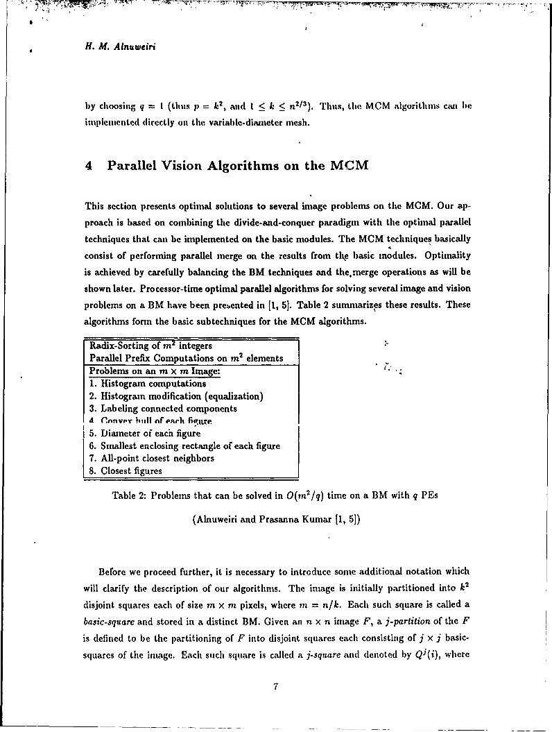
This section presents optimal solutions to several image problems on the MCM. Our ap-
proach is based on combining the divide-and-conquer paradigm with the optimal parallel
techniques that can be implemented on the basic modules. The MCM techniques basically
consist of performing parallel merge on the results from the basic modules. Optimality
is achieved by carefully balancing the BM techniques and themerge operations as will be
shown later. Processor-time optimal parallel algorithms for solving several image and vision
problems on a BM have been prezented in [1, 5]. Table 2 sumnarizes these results. These
algorithms form the basic subtechniques for the MCM algorithms.
Radix-Sorting of m2 integersParallel Prefix Computations on m2 elementsProblems on an m x m Image:1. Histogram computations2. Histogram modification (equalization)3. Labeling connected componentsA Cnnvpy huhl of each fipt re
5. Diameter of each figure6. Smallest enclosing rectangle of each figure7. All-point closest neighbors8. Closest figures
Table 2: Problems that can be solved in O(m 2/q) time on a BM with q PEs
(Alnuweiri and Prasanna Kumar [1, 5])
Before we proceed further, it is necessary to introduce some additional notation which
will clarify the description of our algorithms. The image is initially partitioned into k2
disjoint squares each of size m x m pixels, where m = n/k. Each such square is called a
basic-square and stored in a distinct BM. Given an n x n image F, a j-partition of the F
is defined to be the partitioning of F into disjoint squares each consisting of j x j basic-
squares of the image. Each such square is called a j.square and denoted by QJ(i), where
7

H. Al. Alnuweiri
i = 0, 1,-.. ,(k/j)2 -1 is the index assigned to each square. Note that the size of a j-square
is jit x jm pixels. '[lhe squares of a j-partition of the image are indexed such that QJ(i)
is stored in M(i). For j < 2, each Qj(j) can be. partitioned into four equal quadrants,
denoted by Qj, Qj, Q', Qj. Also, note that Qo(i) denotes the basic-square in BM(i). The
boundary of a j-square consists of topmost and botton-most rows of pixels and the leftnost
and rightmost columns of pixels within the j-square. The boundary of an image square Q
is denoted by 6(Q). The pixels on the boundary of a j-square QJ(i) are stored in the PEs
of the boundary BMs of MJ(i).
4.1 Histograinming on the MCM
Histogranuning is a widely used operation in the early processing of images, and in im-
age enhancement applications. The histogrammfing problem can be defined as follows [26]:
Given an n x n image I having H gray-level values 0,1,... , H - 1, compute the number of
pixels having the gray-level value g for each g = 0, 1,..-, H - 1. Each gray'-level value can be
represented by a binary number gh- 1,gh-2, ",go, where h = [logH]. .T'he histogramming
problem for an m x m image can be solved in O(m 2/q) time on a BM withlq PEs by using
the parallel radix-sort technique described in [5] (see table 1). This result is processor-
time optimal since, sequentially, this problem requires fl(rn 2) time. Histogranmning can be
;erformed eIlicie-ntly on the M(.M 1y using data reduction and dtviae-ano-conquer Lech-
niques. Our technique consists of two stages: a sorting stage, and a key-counting stage.
Suppose that the given n x n image consists of If different gray-levels, the two stages can
be performed as follows:
Sorting Stage: Partition the MCM into j-neshes each having a total of at least
H memory locations, i.e. j 2n 2 > H (for simplicity, assume that II = j 2in 2 ). Each
memory location in such a j-mesh corresponds to a distinct key (gray-level value).
Within each j-inesh, sort the pixels by their gray-level values, then compute the sum
of the pixels in each gray-level, and finally, store the sum into the memory location
corresponding to that gray-level key. It is clear the time complexity of this stage is
dominated by sorting the pixels within each j-rnesh, which is O(jl-).
" Key-Counting Stage: This stage is performed using a divide-and-conquer tech-
nique. Since the initial size of each submesh is j X j B Ms, this stage takes logk- logj =
8

H. M. Alnuweiri
log(k/j) iterations. In iteration i, the size of each submesh is (j2i x j2') IMs. lBe-
cause the number of different keys is fixed and equal to Ii, After each iteration the
keys are divided equally among the ltMs of each t-mesh, t = j2'. Fulrthertnore, the
counts (sunt of elements) of the same key in different I-meshes, are stored in the samte
memory location within each I-mesh. Step i of this stage is performed as follows:
1. In this iteration, the sum of pixels for each key in a 21-mesh, t = j2i, is to becomputed by adding the four sums for that key in the four quadrants of the
21-mcsh. Since these-four sums are stored in the same memory location within
each quadrant, this operation can be performed in O(j2' + fm ) time by
rotating the data within each row and column of PEs in a 21-mesh.
2. Now we partition the keys among the rows of each 2t-mesh, so that each RM
will contain a smaller number of keys. This can be done in O(j2' + [ -. ,j)
time by a simple rotation of data in each row and column of memory within each
21-mesh.
The total time taken by the log(k/j) iterations is -
j2' + r-7 --i=O
which is bounded by O(k + 77. /). For processor-time optimality, we must have
_ - = H <irnq q
i.e., the memory size of each BM must be equal or greater than the maximum number of
keys (gray-levels). Thus, we have the following theorem:
Theorem 1 Given art image with 1I or less gray-levels, computing the histogram of theimage can be done in O(k + q . v/77 ) time on an MCM(n, k, q) with p = k2q processors.
fi If = O(m 2), where m = n/k, then the histogram can be computed on this MCM in
O(k "+- M2) = O(k + al) time, which is optimal.
Hlistograms are used in a large number of applications such as image enhancement. For
example, in a certain image some gray-levels may be heavily populated while other levels

H. M. Alnuweiri
may have a umuch lower number of pixels. To enhance the dynamic range of the image, a
redistribution of gray-level values may be desired. This can be done by a technique called
histogram modification [261, in which given a histogram IfM for an image F, it is required
to transform the gray-scale of the image so as to give the image a specified histogram II'"'.
The new histogram has the same number of gray-levels as the old histogram but has a
different number of pixels in each level. It is easy to show that image enhancement by this
method can be performed on an MCM(n, k, q) in 0(k+ V1-) time, where H is the number
of the gray levels. Again, if we choose I = m2 , then this time becomes 0(k + 2-) which is
optimal for 1 < p < n3/2 and I < k < n 2/ 3 .
4.2 Line Detection by the Hough Transform
The Hough Transform is a general technique for feature detection ih images. The method
involves accumulating evidence for parametrized objects from the image feature space [9].
The principle of line detection using the Hough Transform is based oh transforming each
pixel (i,j) in the image (also called the feature space) into a sinusoidalcurve in the param-
eter space. This transformation is defined by the normal representation of a line (passing
through (i, j)), which is given by
o = isinO + icosO. (1)
The computation of the Hough Transform proceeds by. associating an accumulator cell
A(s, t) with each point (p., Ot) (in the parameter space) which keeps a count of the numberof curves intersecting at that point. For computational purposes the ranges of p and 0 are
quantized into a number of levels. If the number of quantized levels of 0 (respectively, p) is
L (respectively, M), then we have ML accumulator cells each associated with a pair (p,, Ot)
of quantized values, where 1 < s < M and 1 < t < L.
Suppose that 01,... ,ALO, are the L given samples of 0, then the Hough Transform can
be computed using L histogramming steps. In Step i, each image pixel (i,j) increments
the count of A(p., 0t) by one, where p, = i sinOt + j cos O. Implementing this technique
directly on the MCM(n,k,q) leads to O(Lk + Ln 2/p) time. The term Ln 2 /p in the time
complexity is within the optimal bound; however, the term Lk is not for sufficiently large
values of k and L, e.g. L = 0(n), k = 0(nt /2 ). The method can be improved by modifying
the key-counting stage of our htstogranuning technique. The complete algorithm is rather
10

lengthy to describe here. We will consider a special case which shows how optititality can
be achieved on the MCM.
Consider computing the Itough Transform of an n x n image. Let L be the number ofvalues of 0 and M be the number of values of p, and let Ii = LM be the total number of
accumulator cells needed to compute the transform. Now let M = in' and L - k, where
as before m = n/k. Each BMi, 1 < i < k2 , has y;2 memory locations which can store
the M = m2 values of p for a particular Oi. In tle computation each BM computes the
Hough Transform for its image pixels for a certain 0. This can be done in O(in2/q) time
by histogramming. The m' values of p are then shifted to an adjacent 13M, so that values
of p for a new value of 0 can be computed. Using this technique each BM computes the
values of p for the L - k values of 0. Since each such computation takes O(m 2 /q) time,
the total time taken by each BM is O(k m2 /q). The data transfer time is also O(k 2m2/q).
Since H - LM - k~m2 , the computation time on an MCM(n,k,q) is O(H/q) = O(L )
using p = k2 q PEs, which is optimal since a sequential computation of the I[T would take
O(Ln2 ) time.
Theorem 2 Computing the fough Transform can be done in O(k + LL' time on anp.
MCM(n, k, q) with p = k~q processors, where L is the number of discrete values of 0 in
* " .. ,.... * rm""Tn"
4.3 Computing Image Connected Components
A black and white (binary) image may consist of several connected regions of black pixels.
A connected component (or a figure) is a maximally connected region of black pixels. The
image labeling problem is to identify a unique label with each figure in the image. The
labeling problem can be solved by using a bottom-up recursive procedure in which the
figures in a k x k square are labeled first by labeling the connected regions within eachk X A quadrant of the square, then by using the adjacency information along the commnon
boundaries of the quadrants to label the connected regions within the k x k square. Nassini
and Sahni have proposed this approach for meshes [201, and since then it was implemented
on several other parallel organizations such as the pyramid computer [191, MOT [231, and
hypercube computers [8]. The same technique can be implemented on the MCM as follows:
tt
H. M. Alnuweiri
Initially, the figures within each basic-square can be labeled in O(-!--) time by using a
niodule-algorithn. Next, a recursive merging algorithm is used to compute the labels of
the figures. The algorithml consists of logk iterations. In iteration i, I < i < logk - 1, tile
figures within each j-squarc, j = 2', are labeled by considering the pixels on the boundaries
of its four quadrts. The merge is done first by constructing an auxiliary graph Gj(h)
representing the connectivity among the figures in the four quadrants of each Qj(h), then
computing the connected components of each such graph. Each vertex in Gj(h) represents
a figure which intersects the boundary of a quadrant. The edges of Gj(h) are constructed
as follows: (v,, v,)cE if two figures labeled z and y in two adjacent quadrants have at least
two pixels which are 4-neighbors along the common boundary pf the tw'o quadrants. It is
clear that Gi has O(jm) vertices and O(jm) edges.
Lemma 1 Given the graph Gi constructed as above, and stored in a~j-mesh, the connected
components of this graph can be computed in O(j + V'. M . log(im)) time.
Proof: The O(jm) edges of the given graph G are stored in a column (or row) of boundary
BMs. Let these edges be stored in the leftmost column of BMs in the j-mesh. The connec-
tivity algorithm we use is basically an implementation of the parallel connectivity algorithm
in [281. For a graph with jm vertices, this algorithm requires O(log(jm)) iterations on a
CROW PRAM with U(jm) Pbs. In each step, each Pi performs a constant. time operation
on its local data. To implement this algorithm on the MCM, each read/write step on the
PRAM is simulated by a random access read/write operation [21] on the MCM. Once each
PE has the appropriate data in its RM, it performs the desired operations on this data.
To implement this algorithm on a j-mesh in which GC is stored, we first move the O(jm)
edges of the graph into a 2r i /l - mesh within the j-mesh, where as before j = 2'. This can
be done as follows: First partition the 2' BMs into 2f i/21 groups, each consisting of 21i /2j
BMs. Move the data within each such group into a distinct column of BMs, such that the
2[ i /21 groups are stored in 2 tV/2J adjacent columns of BMs. This can be in 0( 2[i/21 + m/q)
time by moving the data within each row of PEs. The data within each such column of
BMs is moved upward (within the j-mesh) so that all the edges are now in a 2Li/2 J x 2[i/21
array of BMs. If i is even then this array constitutes a v'j-mcsh. If i is odd then this array
constitutes the upper half of a 2 ri/21-mesh. Each PE within the smaller mesh has O(m/q)
edges only in its RM. This data movement is illustrated in figure 4, and it can be completed
12

fH. M. Alnuweirib
in 0(2' A. 211/21 ii/q) time.
am Memory module
000 I0000001311 I 0011 0Do000 Z~1~loo o OlOo o ilo oo :o'o o' ooo01 O o oooo mI I~ O11000010 'o 0 'IOuo o I
0000000 jg 0 0 C3gIIg~
'Coaooo o a 00 a a a4DIaaIU ooIooaDOO I Ioolalool lgml IoRIH oo ara 0 9oo
I3 90 o MOo lO 10 13M o30 013 H 1oooo1 1oQaO O D a TO all 3 o1 o 13 a 1/
I l 1 1 loo0 0 0ooo 1o GOO11D at i aoo oo oooo 0 oo1oo30 1o o 1 I o o 2 Io ago 0 o aoooo o oo.o.o E ooao 100o aonoolloooo l looooloao soo io 0ooooaooo oloaollaOOallaOO Ioooollo0OOl OUa o 0al 00I OOOlO aoo soon
ooo o o 0~ .~.ogoo0110oI L o o o1 sg 00 0__ o Og lOO a do110g .~l 00loooooooololWI 00 Io1ooo1o o ' oO o a oo 1olGua
1 9oo ooaoooooloOMD R 00 aom oo l a o OlOo O oo o 000 3lO 3 Dao oo0lGoooooooooo1oaO 00 ooolooooooIo o Olooo DOO o o3o 00o aoa
oaooooori ~ ~ ~ ~ ~ ~ 1 0 0 g go0l00~j ggl~gn0000o13oo 110 o0 .al b a al 00 o OO No o o 1o Gu l I alOo laam Oll aoo00
Move data along rows Concentrate data along columns Final position of data
Figure 4: Concentrating data into a smaller submesh
Within the 2/1-mesh, each random access read/write operation n 13 e performed in
O(2Fi/21lm/q) = O(V3'. (m/q)) time [21. Thus, the log(jmn)iterations of the connectivity
algorithm in [28] can be performed in O(\/3. (m/q) . (log im)) time. 0
After c:omputing the connected componetits of C3, the correct jabeis of tiie pixeis on
the boundiary of each j-square (and also on the boundary of its four quadrants) can be
computed. The procedure is then repeated for each (2j)-square, (4j).square, and so onuntil the entire ag has been processed. The time for iteration i of the algoitlun is
O(j + V-• log(ja)), where j = 2 , and the time for the initial module computation is
O(m2 /q). Thus, the time for all logk iterations is,
log km/q + [ can+ 2/n(m/q)(log2m))
i=1
which is bounded by O(k + m2/q) = O(k + n2 /p), where p = koq.
Since only the labels of the pixels on the boundary of each quadrant are updated in
eacl iteranti ome i as ll have old incorrect labels at the end of the comiputa-
tion. These pixels can be labeled with the correct labels by applying a top-down recursive
procedure similar to the above procedure but in the reverse direction. That is, use the
13

II. M. Alnuweiri
labels of tle pixels ott the )otln(lary of each j-squareto label Lite pixels On Lite boundaries
of its four quadrants. This is (lone starting front tle square Qk which consists of tle entire
it X n image, and then applying the technique until the size of each quadrant is In X In
pixels. Each such quadrant is local to one BM and its pixels can be labeled with the correctlabels in 0(m 2 /p) time using a niodule-algorithm. The following theorem summerizes this
result.
Theoremn 3 Given an n x n black and white image, all connected regions of black pixels
in the image can be labeled in 0(k + n2/p) time on an MCM(n, k, q) with p PEs, where1_p n3/2 and k<n 2/ 3 .
Besides being optimal, our result is superior to previous known results. For example,
using n3 /2 the MCM can provide 0(n'/2) time solution to the above problem. A pyramid
computer can provide the same solution time but using It2 PEs [19]. A 2MCC with n 2
PEs provides 0(n) time solution to this problem [20]. The hypercube and shuffle-exchange
networks can provide 0(log2 n) time solutions using n2 PEs [8], but they require a much
larger area if implemented in VLSI.
We now consider the problem of computing the convex hull of each figure (connected com-
ponent) in -an n x ?I image in which all figures have been labeled. A set S of pixels is said
to be convex if the smallest convex polygon containing them contains no other pixels. Such
polygon is called the convex hull of S, and it is denoted by CH(S). Tile MCM algorithm
is base' ie divide-and-conquer paradigm for merging disjoint convex hulls [25]. Two
conv, .ais are said to be disjoint if there exists-a vertical line in the plane such that all the
vertices of one hull lie on or to the left of this line, and all the vertices of the second hull lie
to the right of this line. By merging two convex hulls A, and A2, we mean computing the
convex hull CH(Ai,A 2 ) of At and A2. Merging two disjoint convex polygons At and A2
can be done by computing the two tangents common to At and A2, and by eliminating the
vertices which become internal to the resulting polygon. To compute these tangent lines,
it is useful to partition At (A2) into an upper hull and a lower hull. Let t and r be the two
vertices with, respectively, the smallest and largest i-coordinates among all the vertices of
14

I. M. Alnuweiri
co1nn1111 tangent - - --
UH2
- --' - -
0 Marked vortex(each is stored ina record with
the two edges Incident upon it)
Figure 5: Partitioning convex hull
A1 (A2). The upper hull consists of all the vertices of A, (A2) which lie on or above the
line tr, and the lower hull consists of all the vertices below this line.
Our merging technique is based on the following procedure: Suppose we have two convex
hulls (polygons), C11 and C112. We consider the merge procedure for the upper two
hulls of CI1 and CI12 (denoted UI1 and U1[2, respectively). The same procedure can
be applied to merge the lower hulls. Let ulti= (vI,v 2 ,... ,v.) and UH2= (ui,U2, .",u,),
where the vi's (ui's) are the vertices UlI (UI[2) given in the increasing order of their
z -coordinate (see figure 5). Mark j vertices V = (vi,, vi, - ,v Iii) from UI[i and j vertices
U = (Uitli2l"'IUi,) from UH2, where vi, = v1, vi, = V,, ui, = ul, and ui, = u,. The
marked vertices are also ordered by their z-coordinate. The sets V and U partition UI11
and Ulf2 into j - I segments, where a segment [vi., vi, I ([ui, lli,+ 1 ) consists of all the
vertices of UIl (UI[2) in between, and including, vi, and vi, , (uj, and ui,+,). Note that
the segments do not necessarily contain the saine number of vertices. Finally, we assume
each vertex in V (U) is stored in a record together with the two edges from U1l1 (U112)
incident upon it. The two hulls U11I and U112 can be merged in two stages as follows:
Procedure MERGE-IIUL,
* Stage 1: This stage performs the binary search procedure only on the vertices in V
15

H. M. Alnuwteiri
and U and the edges incident upon them. Each iteration of the algorthii consists
of choosing two vertices vi, and ujt, constructing the line joining thetu, and thet
testing if this line is tangent to hoth U1ll atid U112 [251. Thus, this stage terminates
in at most (logj) iterations. Upon terinination, either a common tangent is found
(and we are-done) or two segments of vertices, one from U1il and one from UI[2, are
identified. These two segments contain the two vertices through which the common
tangent passes.
Stage 2: This stage computes the coiUmon tangent by performing the binary search
procedure on vertices of the two segments identified in the previouts stage. This stage
terminates in at most (log t) iteration, where t is the tbtal number of vertices in the
two segments.
To merge pairs of convex hulls in two adjacent image squares' the above two stages
must be applied simultaneously to all pairs of convex hulls which touch along the common
boundary of the two squares. The following steps show how the above procedure can be
implemented on the MCM: .,
1. Initial module computation: We start by computing the convex hulls for all the
figures within each basic square. Since each basic square is local to one BM, this
computation can be completcd in O(m'/q) time using a B1M algorithm. Note t",at if
a figure extends over several basic squares, then this figure will have a convex hull in
each one of these basic squares. All the convex hulls of one figure must be merged in
order to obtain the final convex hull of the figure. For the merge phase, we need only
to consider convex hulls of figures which have at least one pixel on the boundary of a
basic square.
2. Recursive-merge: This phase consists of a recursive procedure which runs in logk
iterations. In iteration i, I < i < logk, we compute the convex hulls of the figures
within each j-square, QJ, where j = 2i. At the beginning of this iteration, the
convex hulls of the figures within each quadrant of Qj have been computed. So we
need to merge each group of (at most four) convex hulls of the same figure in the
four quadrants. It can be shown that all pairs of hulls can be merged in 2 log(jm)
iterations by using a binary-search procedure [25]. Our merge procedure is based on
implementing this binary search technique. The details of the implelentation are
16
a fH. M. Alnuweiri
rather tedious and are left out to the full version of this paper. rhe following theorem
suniuerizes our restilt.
Theorein 4 Given an n x n irnagc in which all figures have been labeled, the Convtex hull
of each figure can be computed, for all figures simultaneously, in O(n 2 /p) time on an
MGM(n, k, q) with p PEs, where I < p < it3 / 2 and k < n2/3 .
Using a similar computation, several other geometric properties can he computed for
each figure in the image. For example, computing the diameter and -a smallest enclosing
rectangle for each figure can be computed in 0(n 2 /p) time on an MCM(n, k, q) with p PEs,
where 1 < p <n 3/2 and k < 2/3 . Again for p = n/2 , the above problems can be solved in
O(n 1 / 2 ) time, which is superior to the O(n) time solution on a standard n x n mesh of PEs
[16], and the O(nh/2 logn) solution on a pyramid computer of size n 2 [19].
4.5 Computing All Closest Neighbors
We consider two problems related to computing distances among image regions. The first
problem we consider is the closest neig,'bor problem. In this problem we are given an n X n
oiacK ana white iroage, and we are required w, cuinipuL, ;or eacit pixcl p (CitbiL 1. u u
white) a closest black pixel. The computed black pixel will be called a closest neighbor of p.
As a measure of distance, we will use the Ll metric. In this metric the distance between two
pixels (i, j) and (u, v) (denoted by DIST[(ij),(u,v)] is given by Ii - ul + Ij - vi. A bottom-up
recursive approach can be used for this problem. To compute the closest neighbor for each
pixel in a j-square square Qj, we first solve the problem within each quadrant of Qj and
then merge the results from the quadrants. It can be shown that in the merge step only
the boundary pixels of the quadrants need to be considered.
The divide-and-conquer procedure proceeds as follows6 Initially, tile closest neighbors
are computed within each basic square. Since each basic square is local to one BM, this
can be done in O(in2/q) time using a module-algorithm. A bottom-up recursive algorithm
is then used. In the beginning of iteration i of this algorithm, I < i < logk, the boundary
pixels of each quadrant of a j-square, j = 2', have computed their closest neighbors within
that quadratit. Iteration i consists of computing the closest neighbors of tile boundary
17

11. M. Alnuweiri
o 01
u.V IV 0)
i i A u.v)
02 03
Figure 6: Closest neighbor computationsft.
pixels of each j-square, by merging the information along the joundaries of its quadrants.
Theorem 5 Given an n x n black and white image, the closest neighlbor of each pixel in the
image can be computed in O(k + n2/p) time on an MCM(n,k,q) with p PEs, 1 < p < 3/
and k < i2t3
Proof: Let Mi be the j-mesh containing the j-square, Qi. and let M(3/2)(t), be the (j/2)-
mesh (within Mj) which contains quadrant Q', 0 < t < 3, of Q3 (see figure 6). The major
stet in the meree procedure is the data transfer needed to enable each pixel on the boundary
of a quadrant to compute its nearest neighbors in the other three quadrants. Once a pixel
has this information, computing its nearest neighbors can be done in 0(l) time. Consider
the pixels on the boundary of quadrant Q1. Each PE in the rightmost column (topmost
row) of BMs in M(j/ 2)(2) reads the closest neighbors of the boundary pixels in its neighbor
PE in the leftmost column (bottom-most row) of BMs in M(3/2)(3) (M(3/ 2)(O)). Since each
such PE has O(rn/q) boundary pixels in its RM, this operation can be completed in O(m/q)
time. The pixel (u - 1, v + 1) in the south-western corner of Q' can be also moved into
the PE containing pixel (u, v) in the north-eastern corner of Q', in 0(i) time. Now the PE
containing (u, v) can compute the closest neighbors of (u, v) within quadrants Q', Q', and
Q'. These three closest neighbors are then broadcast to all boundary PEs in M(/ 2)(2).
This can be (lone in O(j + log q + re/q) time. Now each PE in the rightmost column and
topmost row of BMs in M(j/2)(2), has all thw imtorinatior necessary to compute tlhe corr'ct
distances for each pixel in its portion of tlH boundary. Since each boundary'1f has "7(m,.[r ,
such pixels, this can he done in O(m/q) time. A sidilar computation is perfor vied to n,.date
18

.f. M. Alnuweiri
the closest neighbors of the pixels on the boundary of Qj. Thus, iteration i of the tCrgealgorithn requires O(j + log q + m/q) time, where j = 2'. The tine taken by the entire
algorithln is
71 2 1. 109 (2 log q =o(k +M2q q q
Where the O(in 2 /q) term is the time taken by the initial module-algorithm. Since m = n/k
and p = k2q, the time taken by the algorithm is O(k+n 2/p) which is optimal for < p < n3/2
and k < n2/3. C]
A closely related problem is the problem of computing for each figure F, the label of the
nearest figure to it in the image. As before, define DIST(p, q) to be the distance between
two pixels, p and q according to L1 metric. Thm the label of the nearest figure to figure F,
is the label of the pixel q such that
DIST(p, q) = mn {DIST(p, q)IpEF,q /F}p~q
Corollary 1 Given an n x n image in which all figures have been labeled, a nearest fig-
ure to each figure can be identified, for all figures simultaneously, in O(n 2/p) time on an
JVAL~kAI, q/ WZLIt p FES, Wihtu 1 < p < ,I j, , un' .. _ ,71"
Proof: Let £(p) denote the label assigned to a pixel p, this problem can be solved in
two major steps. In the first step, we compute for each pixel p, a closest neighbor q
such that £(q) 0 £(p). This can be done by using a simple modification of the above
algorithm for computing closest neighbors. In the second step, the nearest figure to each
figure is computed. This can be done by using a slight variation of the component labeling
algorithm. In addition to keeping track of the minimum indexed pixel in th. component,
we also keep track of the label of the closest neighbor with the minimum distance from a
pixel in the component. From theorem 3 we know that this can be done in O(n2/p) time.
At the end of the computation, each pixel labeled F knows the label of the nearest figure
to F. 0
19
H. M. Alnuweiri
5 Concluding Remarks
We have presented several processor-timue optimal algorithms for digitized images on anesh-connected processor array having p PEs and 0(n 2 ) memory. The organization uses
novel conununication capabilities and can be implemented in current VL'SI technology.
The proposed organization has several features which distinguish it from other mesh-basedparallel computers. First, the PEs communicate through a shared memory as well as direct
interprocessor links. Second, the MCM is, in fact, a hybrid of a mesh-connected array
and the coitununication-efficient organization of the basic modules (BMs). This two-level
organization of the MCM implies two types of parallel algoritlums: basic-module algorithmsand communication-algorithms. Balancing the size of each BM and the number of BMs
in the MCM results in processor-time optimal algorithms over a wide range of processor
counts. The image problems considered here require global operations on image pixels, but
are not computationally intensive (they require O(n 2) operations for an n x n image). To
provide optimal solutions to such problems, several efficient data movement operations have
been developed for the MCM. All of these operations are efficient for applications in which
the amount of data in the memory array is reduced (i.e. less than 0 (n'J'); 'hich is the case
for several of the image problems that we have considered. The MCM organization has
been considered to proiide optimal speedups for several classes of problems such as sorting
20
f. M. Alnuweiri
References
[I] It. M. Alnuweiri and V. K. Prasanna Kumar, "Efficient Image Comlputations on VLSIArchitectures with Reduced Hardware", Pro.c. IEEl Workshop on Computer Archi-tecture for Pattern Analysis and Machine Intelligence, Seattle, WA, 1987.
[21 It. M. Alnuweiri and V. K. Prasanna Kumar, "Optimal VLSI Sorting with ReducedNumber of Processors", Tednical Report, IRIS 225, USC, 1987.
[31 It. M. Alnuweiri and V. K. Prasanna Kumar, "O ;tinial Geometric Algorithms on Fixed-Size Linear Arrays and Scan Line Arrays", Proc. IEEE Conference on Computer Visionand Pattern Recognition, 1988.
[4) It. M. Alnuweiri and V. K. Prasanna Kumar, "A Reduced Mesh of Trees Organizationfor Efficient Solutions to Graph Problems", Proc. the 22nd ,Annual Conference onInformation Science and Systems (CISS), Princeton University, March 1988.
[5] H. M. Alnuweiri and V. K. Prasanna Kumar, "Optimal image Computations on Re-duced VLSI Architectures", to appear in IEEE Transactions on Circuits and Systems,October, 1989.
[6] H. M. Alnuweiri and V. K. Prasanna Kumar, "Fast Image Labeling Using local Op-erators on Mesh-Connected Computers", Proc. International Co..ference on ParallelProcessing, 1989.
[71 K. E. Batcher, "Design of A Massively Parallel Processor", IEEE Transactions onComputers, c-29, September 1980.
[8] R. Cypher, J. L. C. Sanz, L. Snyder, "Hypercube and Shuffle-Exchange Algorithms forImage Component Labeling", Proc. IEEE Workshop on Pattern Analysis and MachineTnfall;a~nio . q ff'lp . WA IQR7
[9] R. 0. Duda and P. E. Hart, "Use of the Hough Transformation to Detect Lines andCurves in Pictures", Communications of the ACM, 15, 1, 1972.
[10] C. R. Dyer, "A VLSI Pyramid Machine for Hierarchical Parallel Image Processing",Proc. IEEE Conference on Pattern Recognition and Image Processing, 1981.
[1.1 C. R. Dyer and A. Rosenfeld, "Parallel Image Processing by Memory Augmented Cel-lular Automata", IEEE Transactions on Pattern Analysis and Machine Intelligence,1981.
[12] K. Hwang and POS. Tseng and D. Kim, "An Orthogonal Multiprocessor for ParallelScientific Computations", IEEE Transactions oi Computers, c-38, January 1989.
[13) J. Ja'Ja' and R. M. Owens, "An Architecture for a VLSI FFT Processor", INTEGRA-TION the VLSI Journal, 1, 1983.
[141 F. T. Leighton, "Parallel Computations on Meshes of Trees", Technical Report, MIT1982.
[151 It. Miller, V. K. Prasanna Kumar, D. Reisis, Q. F. Stout, "Meshes with reconfigurablebuses", Proc. MIT Conference on Advanced Research on V1,S1, Cambridge, MA, 1988.
21

11. M. Alnuweiri
1161 It. Miller and Q. F. Stout, "Geometric Algorithms for l)igitized Pictures on A Mesh.Connected Computer", [EEE Transactions on Pattern Analysis and Machine Intelli-qence, March 1985.
1171 It. Miller and Q. F?. Stout, "Varying Diametfr and Problem Size on Mesh-ConnectedComputers", Proc. International Conference on Parallel Processing, 1985.
[181 It. Miller and Q. F. Stout, "Varying Diameter and Problem Size on Mesh-ConnectedConipiters", Proc. International Conference on Parallel Processing, 1985.
[191 R. Miller and Q. F. Stout, "Data Movement Tedniques for the Pyramid Computer",SIAM Journal on Computing, 2, 1987.
[20] 1). Nassinti and S. Sahni, "Finding Connected Components and Connected Ones on aMesh-Connected Parallel Computer", SIAM Journal on Computirg, 9, 4, 1980.
[21] D. Nassini and S. Sahni, "Data Broadcasting in SIMD Computers", IEEE Transactionson Computers, c-30, 2, February 1981.
[22] D. Nath, S. N. Maheshwari, P. C. P. Blhatt, "Efficient VLSI Networks for ParallelProcessing Based on Orthogonal Trees", IEEE Transactions on Computers, c-32, 6,June 1983.
[23] V. K. Prasanna Kunar and M. Eshaghian, "Parallel Geometric Algorithms for Dig-itized Pictures on Mesh of Trees Organization", Proc. International Conference onParallel Processing, 1986.
[24] V. K. Prasanna Kumar and C. S. Raghavendra, "Array Processor with Multiple Broad-casting", Journal of Parallel and Distributed Computing, 4, 173-190 (1987).
(25] F. Prepaiata and S. J. Hong, "Convex Hulls of Finite Sets of Points in Two and Three, 4 .. . . ". a"... ..L. . A/Y-,f T4., --.. " I '7.
[26] A. Rosenfeld and A. C. Kak, Digital Picture Processing, Academic Press, New York,1982.
[27] I. D. Scherson and S. Sen, "Parallel Sorting in Two-Dimensional VLSI Models of Com-putation", [EEE Transactions on Computers, c-38, 2, 1989.
(28] Y. Shiloach and U. Vishkin, "An O(logn) Parallel Connectivity Algorithm", Journalof Algorithms, 3, 1982.
[29] P. S. Tseng, K. lIwang, V. K. Prasanna Kurnar, "A VLST Based Multiprocessor Ar-chitecture for Implementing Parallel Algorithms", Proc. International Conference onParallel Processing, 1985.
[30] J. Ullman, Computational Aspects of VLSI, Computer Science Press, 1984.
[31] S. II. Unger, "A Computer Oriented towards Spatial Problems", Proceedings of thefi1E, v. 46, pp. 1744-1754, 1958.
22