DTIC · FIELD GROUP SUB-GROUP 4 Army air toair helicopters; Eyegaze pointing tasks, 01 03 01...
81
wi h FILE COPY 1AD Technical Memorandum 21-89 COMPARISON OF OCULOMETER AND HEAD-FIXED RETICLE WITH VOICE OR SWITCH AND TOUCH PANEL FOR DATA ENTRY ON A GENERIC TACTICAL AIR COMBAT DISPLAY " Christopher C. Smyth N Mary E. Dominessy November 1989 AMCMS Code 612716.H700011 DTIC ELECTE JAN 301990 Approved for public release; distribution is unlimited. U.S. ARMY HUMAN ENGINEERING LABORATORY Aberdeen Proving Ground, Maryland 21005-5001 10 003
Transcript of DTIC · FIELD GROUP SUB-GROUP 4 Army air toair helicopters; Eyegaze pointing tasks, 01 03 01...

wi h FILE COPY
1AD
Technical Memorandum 21-89
COMPARISON OF OCULOMETER AND HEAD-FIXED RETICLEWITH VOICE OR SWITCH AND TOUCH PANEL FOR DATAENTRY ON A GENERIC TACTICAL AIR COMBAT DISPLAY
" Christopher C. SmythN Mary E. Dominessy
November 1989AMCMS Code 612716.H700011 DTIC
ELECTEJAN 301990
Approved for public release;distribution is unlimited.
U.S. ARMY HUMAN ENGINEERING LABORATORYAberdeen Proving Ground, Maryland 21005-5001
10 003

C
%DEC, PDP, UNIBUS, VAX, VMS are registered trademarks of DigitalEquipment Corporation.
®Carroll Touch is a registered trademark of Carroll Touch Incorporated.
Interstate VRM is a registered trademark of Interstate ElectronicsCorporation.
NAC Eyemark Recorder is a registered trademark of NAC Incorporated.
OPolhemus Navigation Sciences Division 3Space and Polhemus Isotrak areregistered trademarks of Polhemus Navigation - Sciences Division,McDonnell Douglas Electronics Company, McDonnell Douglas Corporation.
@SAS Statistical Analysis Computer Package is a registered trademark ofSAS Institute Incorporated.
Destroy this report when no longer needed.Do nit return it to the originator.
The findings in this report are not to be construed as an official Departmentof the Army position unless so designated by other authorized documents.
Use of trade names in this report does not constitute an official endorsementcr approval of the use of such commercial products.

REPORT DOCUMENTATION PAGE IForm ApprovedOMB No. 0704-0188
la. REPORT SECURITY CLASSIFICATION lb RESTRICTIVE MARKINGS
Unclassified2a. SECURITY CLASSIFICATION AUTHORITY 3 DISTRIBUTION/AVAILABILITY OF REPORT
2b. DECLASSIFICATION /DOWNGRADING SCREDULE Approved for public release;distribution is unlimited.
4. PERFORMING ORGANIZATION REPORT NUMBER(S) 5. MONITORING ORGANIZATION REPORT NUMBER(S)
Technical Memorandum 21-89
6a. NAME OF PERFORMING ORGANIZATION 6b. OFFICE SYMBOL 7a. NAME OF MONITORING ORGANIZATION(If applicable)
Human Engineering Laboratory I SLCHE
6c. ADDRESS (City, State, and ZIP Code) 7b. ADDRESS (City, State, and ZIP Code)
Aberdeen Proving Ground, MD 21005-5001
8a. NAME OF FUNDING/SPONSORING Sb. OFFICE SYMBOL 9. PROCUREMENT INSTRUMENT IDENTIFICATION NUMBERORGANIZATION (If applicable)
8C. ADDRESS (City, State, and ZIP Code) 10. SOURCE OF FUNDING NUMBERSPROGRAM PROJECT TASK IWORK UNITELEMENT NO. NO. NO. ACCESSION NO.
6.27.16 L162716AH7
11. TITLE (Include Security Classification)
Comparison of Oculometer and Head-Fixed Reticle With Voice or Switch andTouch Panel for Data Entry on A Generic Tactical Air Combat Display
12. PERSONAL AUTHOR(S)
Smyth, Christopher C., Dominessy, Mary E.13a. TYPE OF REPORT 13b. TIME COVERED 14. DATE OF REPORT (Year, Month, Day) 15. PAGE COUNT
Final FROM TO 1989, November 7716. SUPPLEMENTARY NOTATION
17. COSATI CODES 18. SBJECT. TERMS (Continue on reverse if necessary and identify block number)
FIELD GROUP SUB-GROUP 4 Army air toair helicopters; Eyegaze pointing tasks,
01 03 01 tactical air combat displayi head-fixed reticle"23 02 J Oculometer5; touch panel
19. ABSTRACT (Continue on reverse if necessary and identify by blocklnumber)
An experiment with 15 U.S. Army enlisted military subjects was conducted to compare
the use of a head-mounted oculometer, a head-fixed reticle, and a touch panel for dataentry tasks on a generic tactical air combat display. The oculometer and the fixed reti-cle were operated in a head-free mode and were used with either switch or voice. Thefixed reticle with switch, the oculometer with switch, and the touch panel are signifi-
cantly faster than Lhe fixed reticle with voice and the oculometer with voice. The fixedreticle methods are faster than the oculometer methods of the same modality. The switchmethods are faster than the voice methods. The ocular pointing methods (whether oculom-eter or fixed reticle, voice or switch input) require a larger display activation window(+1.1 inches at 27 inches' viewing distance) than does the touch panel, thereby limiting
the number of selections that can be shown on the display. This Is especially true forthe oculometer with voice method which generated significantly more selection errors andmay therefore require a still larger display activation window for proper operation."
20. DISTRIBUTION/AVAILABILITY OF ABSTRACT 21 ABSTRACT SECURITY CLASSIFICATION
0 UNCLASSIFIED/UNLIMITED 0 SAME AS RPT - DTIC USERS Unclassified
22a. NAME OF RESPONSIBLE INDIVIDUAL 22b TELEPHONE (Include Area Code) 22c OFFICE SYMBOL
Technical Reports Office (301) 278-4478 SLCHE-SS-IR
DD Form 1473. JUN 86 Previous editions are obsolete. SECURITY CLA5;IFISATIQN OF THISAGE

AMCMS Code 612716.H700011 Technical Memorandum 21-89
COMPARISON OF OCULOMETER AND HEAD-FIXED RETICLE
WITH VOICE OR SWITCH AND TOUCH PANEL FOR DATA
ENTRY ON A GENERIC TACTICAL AIR COMBAT DISPLAY
Christopher C. SmythMary E. Dominessy
August 1989
eqHN D.rWEISZ :Nirector
Human Engineering Laboratory
Approved for public release;distribution is unlimited.
U.S. ARMY HUMAN ENGINEERING LABORATORYAberdeen Proving Ground, Maryland 21005-5001

ACKNOWLEDGMENTS
Mr. Joseph F. Dunn, Service Support Division Test Branch (SSDTB), HumanEngineering Laboratory (HEL), in consultation with the senior investigator,designed and built in the best tradition of the skilled craftsman, a headsupport system for the NAG Eyemark oculometer that enabled the successfulconduct of this experiment.
copy~
A*6689108 For
RTIS GRA&IDTIC TAB 3tUnazwounced 0Justltton
Ditribution/_...
AvalabIlIty Codes, iiil lan/ol
Diet S Oie.1

CONTENTS
EXECUTIVE SUMMARY . . . . . . . . . . . . . . . . . . . . . . . . . . . 3
INTRODUCTION ............... ............................. 5
OBJECTIVE ............... ............................... 7
METHODOLOGY ............... .............................. 7
Apparatus .............. ............................ 7Test Subjects ........... .......................... .. 28Experimental Design ......... ....................... ... 28Training and Test Procedures ......... ................... 30
RESULTS ............. ................................ ... 32
DISCUSSION ............ .............................. ... 42
CONCLUSIONS ............... .............................. 67
RECOMMENDATIONS FOR FURTHER RESEARCH ...... ................. ... 67
REFERENCES ............ .............................. ... 69
APPENDIX
Posttest Questionnaire and Results ...... ................ ... 71
FIGURES
1. Eyemark Oculometer: Front View ....... ............... 102. Eyemark Oculometer: Right-Front View ... ............ . i.113. Test Station ..... ......................... 134. Subject Using Touch Panel. .................. 155. Subject Using Oculometer With Push Button .. .......... ... 166. Tactical Display Screen ....... ................... ... 177. Display Screens for Data Request Task
Using Switches as Input Modality ..... ............... ... 198. Display Screens for Identification Report
Task Using Switches as Input Modality ... ............ ... 209. Display Screens for Data Request Task Using
Voice as Input Modality ....... ................... ... 2110. Display Screens for Identification Report
Task Using Voice as Input Modality ..... .............. ... 2211. Display Screens for Data Request Task Using
Touch Panel as Input Modality ...... ................ .. 2312. Display Screens for Identification Report
Task Using Touch Panel as Input Modality ... ........... ... 2413. Calibration of Oculometer ......... .................. 3314. Calibration Pattern for Oculometer ..... .............. ... 3415. Calibration Check of Oculometer ..... ............... ... 35
1

16. Task by Method Interaction for TrackSelect Task Time (Ti) .................... .......... 47
17. Task by Method Interaction for SubmenuSelect Task Time (T2) .......... .................... 48
18. Task by Method Interaction for SubtaskCompletion Time (T3) ........ ..................... ... 49
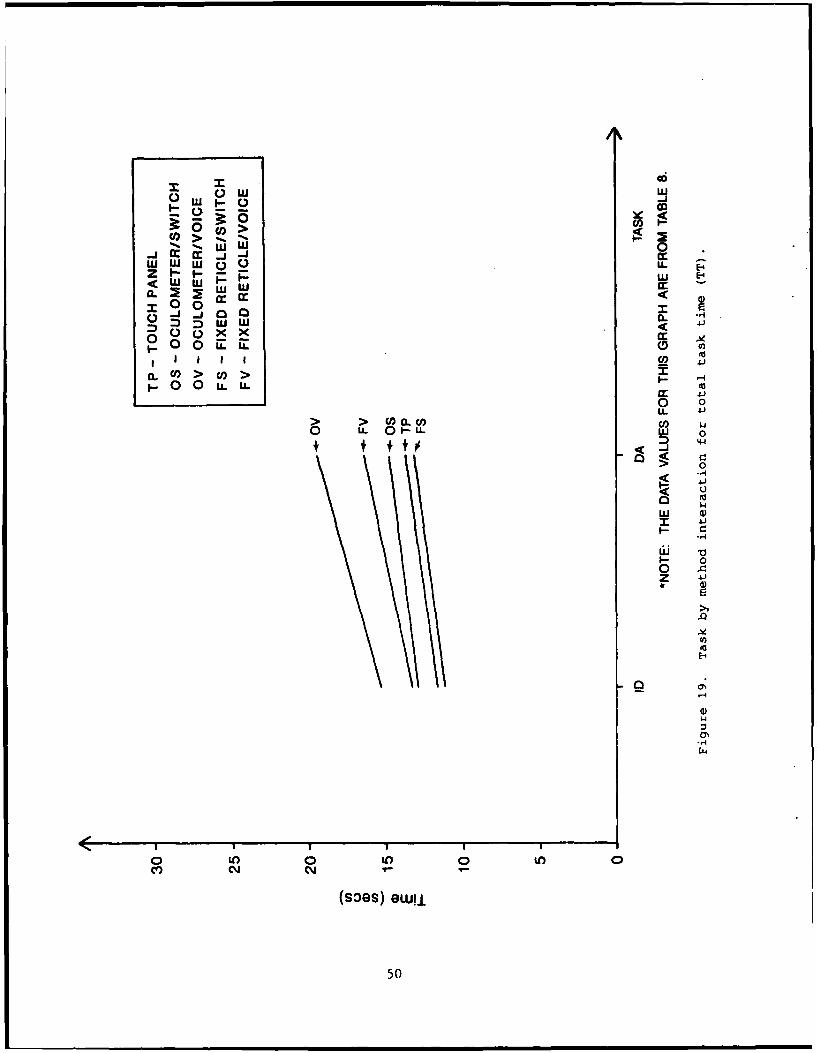
19. Task by Method Interaction for Total Task Time (TT) ..... . 5020. Spatial Tolerance Frequency Distribution by Method ... ...... 65
TABLES
1. Display Screen Size and Characteristics ... ........... ... 182. Scenario Track Probabilities ...... ................. ... 263. Test Subject Demographic Data ........ ................ 294. Testing Sequence Assignments ...... ................. ... 365. Results of the Repeated Measures Multivariant
Analysis of Variance for the Transformed TimeVariables: Wilks Criterial and Mauchly's Criteriafor Sphericity, the Correlation of the Meansamd Variances, and the Normality Test ... ............ ... 38
6. Univariate Analysis of Variances for Within-SubjectEffects of the Transformed Time Variables .. .......... ... 39
7. Scheff5's Test for the Methods ...... ................ ... 408. Chi-Squared Analysis of the Total Errors by Task,
Method, and Task by Method Interaction (0.05Significance Level) ........ ..................... ... 41
9. Descriptive Statistics for the Task Times and TotalErrors for the Method by Task Interaction: Number,Average, Standard Deviation, and Standard Error . ....... . 43
10. Statistical Analysis of the Subjects' PreferenceRatings by the Friedman Two-Way Analysis of Variancefor Related Samples ........ ..................... ... 45
11. Statistical Analysis of Subject Errors by Error Type .. ..... 5112. Statistical Analysis of the Selection Errors as a
Function of Subtask ..................................... ... 5413. Statistical Analysis of the Relationship Between the
Times and Errors of the Select-Track Subtask .. ......... ... 5714. Statistical Analyses of the Difference Between the
Average Times for Error-Free Runs and Total Runs ... ....... 6015. Statistical Analysis of the Error-Free Times .. ......... ... 6116. Descriptive Statistics for the Spatial Tolerance
of the Track Selection Subtask Number, Average,Minimum (MIN), Maximum (MAX), and StandardDeviation (SD) ......... ........................ ... 63
17. Frequency Distribution of the Spatial Toleranceof Each Method ......... ........................ ... 64
18. Descriptive Statistics of the Spatial ToleranceDistributions for the Methods ...... ................ .. 66
2
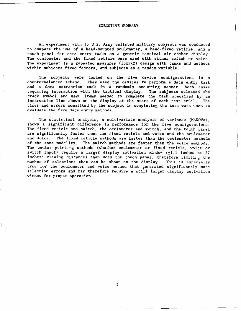
EXECUTIVE SUMMARY
An experiment with 15 U.S. Army enlisted military subjects was conductedto compare the use of a head-mounted oculometer, a head-fixed reticle, and atouch panel for data entry tasks on a generic tactical air combat display.The oculometer and the fixed reticle were used with either switch or voice.The experiment is a repeated measures (15x5x2) design with tasks and methodswithin subjects fixed factors, and subjects as a random variable.
The subjects were tested on the five device configurations in acounterbalanced scheme. They used the devices to perform a data entry taskand a data extraction task in a randomly occurring manner, both tasksrequiring interaction with the tactical display. The subjects selected thetrack symbol and menu items needed to complete the task specified by aninstruction line shown on the display at the start of each test trial. Thetimes and errors committed by the subject in completing the task were used toevaluate the five data entry methods.
The statistical analysis, a multivariate analysis of variance (MANOVA),shows a significant difference in performance for the five configurations.The fixed reticle and switch, the oculometer and switch, and the touch panelare significantly faster than the fixed reticle and voice and the oculometerand voice. The fixed reticle methods are faster than the oculometer methodsof the same modrlity. The switch methods are faster than the voice methods.The ocular point ig methods (whether oculometer or fixed reticle, voice orswitch input) require a larger display activation window (±i.1 inches at 27inches' viewing distance) than does the touch panel, therefore limiting thenumber of selections that can be shown on the display. This is especiallytrue for the oculometer and voice method that generated significantly moreselection errors and may therefore require a still larger display activationwindow for proper operation.
3

COMPARISON OF OCULOMETER AND HEAD-FIXED RETICLE WITH VOICE OR SWITCH
AND TOUCH PANEL FOR DATA ENTRY ON A GENERIC TACTICAL AIR COMBAT DISPLAY
INTRODUCTION
It is expected that high work loads will be imposed on pilots in singlecrew military helicopters during the air-to-air combat role. This isespecially true during the target acquisition phase of air combat when thepilot is interacting with an on-board panel-mounted tactical air combatdisplay used for target alerting and cuing. The pilot will need to specifythe display tracks of interest to amplify flight data as an aid in selectingpotential targets. The pilot may orient himself toward the target from thedisplay. He must then acquire the target with the fire control sensor anddesignate fire engagement. He may have to visually confirm an enemy targetbefore engagement depending on the rules of engagement. This process musttake place as quickly and effectively as possible if the pilot is to surviveover the battlefield.
Several alternate methods of display interaction are investigated aspossible means of reducing this work load through reduced data entry timesduring display interaction. The methods are relatively novel soldier-displayinterface mechanisms based on the direct coupling of the visual process andthe display control mechanism. One such method is based on the use of a head-fixed reticle for alignment with a display item of interest, and another on anoculometer to designate the eye gaze direction.
The head-fixed reticle concept has been incorporated into on-boardhelicopter fire control systems to designate visually acquired targets outsidethe aircraft for fire engagement. For example, the pilot of the Apache attackhelicopter uses the Honeywell Integrated Helmet and Display Sighting System(IHADSS) to designate targets. The pilot moves his head so that the fixedreticle on the monocular helmet-mounted display is aligned with the image ofthe intended target. The sensor of the armament system slues with the headmovements of the pilot, and the target is acquired by pushing a switch, orpossibly (in the future) by speaking an engage fire command.
An alternate target designation method would employ oculometers. TheArmy and NASA have proposals under contract to develop head-mountedoculometers for target designation in the single pilot Light HelicopterExperimental (LHX) cockpit. In this case, the pilot needs only to look at theintended target as the oculometer measures his gaze direction and to press aswitch or voice the appropriate command to acquire the target. The concept ofusing oculometers for military fire control is well established (Setterholm,1982). A helmet-mounted eye tracker was invented for the Navy (Breglia, 1981)for fire control. The Air Force has supported research in using targettracking that employs eye movements with a Honeywell remote panel-mountedoculometer (Meyer, 1981). A head position sensor must be integrated with ahelmet-mounted oculometer for extension to weapon system pointing and cockpitpanel display control.
5

The on-board tactical air combat display, envisioned for the air-to-air
helicopter as an early warning and cuing device, will be included in the
Forward Area Air Defense (FAAD) automated system planned for the 1990s. TheArmy is currently working toward autou~ting the transmission of track alerting
and cuing and command and control (C ) information to the aviation elements
and air defense fire units. The information will appear oi tactical displays
within the FAAD command, control, and intelligence (C I) system at the
battalion, battery, platoon, and fire unit level. Similar information would
be sent to displays within the aviation command and on the flight elements.
The displays would show the aircraft detected by the FAAD system withinthe immediate area as symbols on a tactical map display. The displays wouldallow rapid communication of tactical information between units andheadquarters. The high performance of modern aircraft necessitates the earlyalerting and cuing of the fire units and aviation elements about the presenceof aircraft within their area.
An on-board air combat tactical display will benefit the Army air-to-air
combat helicopter. The recent development of Army air-to-air combat
helicopter capabilities is in response to the Soviet arming of the HINDhelicopter as a defense of their tank forces against allied helicopterantiarmor attack. They have extended this effort to the development of air-to-air combat helicopter airframes. The Army air-to-air combat helicopter,either a redesigned Apache or the new LHX, would be used to defend alliedground attack helicopters. Another role, recently considered, is active airdefense units in which air-to-air helicopters would be directed to intercept
attacking enemy helicopters or aircraft before they reach the defending groundforces.
The inclusion of a tactical display on-board the air-to-air combat
helicopter would allow the pilot the same advantage of early alert and cuingthat the FAAD system affords the fire units. The pilot would be able to planapproach routes and select interception points from the display. He would be
forewarned of the presence of enemy threats in the area and be able to takeevasive action. Furthermore, the pilot will be able to interact with thedisplay and report tactical intelligence to higher headquarters about enemyair activities of interest to both aviation and air defense elements.
The method that the helicopter pilot uses to retrieve information fromthe tactical display will partly determine its usefulness. This is certainlytrue for the single pilot LHX. The pilot must direct most of his attention tothe primary task of continually flying the aircraft; the secondary task ofdisp,.ay interaction should require little attention during air-to-air combat.This is especially true for helicopter displays with their small size. Allinformation available about aircraft in the immediate area is stored in atrack data file within an on-board computing processor. The information is
updated every few seconds from the open digital data FAAD broadcast and thehelicopter's satellite navigation system. However, all information aboutevery track cannot be displayed simultaneously on the tactical display becauseof the limited size of the display. The pilot chooses the track symbol ofinterest from the display and then retrieves the track data information (wingtype, airspeed, altitude, heading, number) needed to compute a reasonableintersection point. Similar comments apply to transmitting an intelligencemessage of the status of observed aircraft. The pilot interacts with thedisplay by "capturing" ("hooking" in air defense nomenclature) the display
6

symbol of interest and then selecting the appropriate menu action. Capturingor hooking is defined as selecting a target symbol from the display andtagging it for further processing.
An effective method of display interaction would be similar in modalityto that used by the pilot for target engagement to prevent confusion betweentasks and reduce work load. A research question of interest is whether thepilot can use these ocular-based methods, developed for outside targetdesignation, to interact with the on-board displays, particularly with thetactical air combat display.
OBJECTIVE
The purpose of this study is to compare the performance, as measured bythe data entry times and errors, of an oculometer with switch or voice, ahead-fixed reticle with switch or voice, and a touch panel as data entrymethods on a generic tactical air combat display. The touch panel is includedfor comparison of the ocular-based methods to a standard display interactivedevice.
METHODOLOGY
The apparati, test subjects, experimental design, and training and testprocedures are described in this section.
Apparatus
The apparati used in this experiment are listed below. The operatingcharacteristics and limitations of the equipment that are pertinent tounderstanding the experimental procedures and results are described in thissection. The following apparati were used in this experiment:
1. DEC VAX 11/780 host computer consisting of a central processingunit, a floating point accelerator, and 2.75 megabytes of memory. Thecomputer has UNIBUS adapter interfaces to an Aydin display processing unit,real time clock, discrete digital input and output switches, analog-to-digitalconverters, and communications ports to VT100/220 terminals. The VAX VirtualMemory System (VMS) operating system supports the FORTRAN language in realtime simulation of military systems. The VMS language provides the priority,scheduling, process creation and control, real time event-driven response, andhigh speed, interprocess communications essential for real time simulation ofcomplicated systems.
2. Aydin graphics system (model 5216 display computer) providing a1024- by 1024-pixel resolution. The system has five memory planes that cangenerate 16 simultaneous colors with an overlay for alphanumerics. The memorybus controller and processor controls vector and character generation, andpermits pixel loading from the host computer at 800 pixels per second. The
7

refresh memory modules provide a 1024- by 1024- by 5-pixel storage resolutionfor the video output. Interface to the host computer is by a parallel DR11-Wdirect memory access UNIBUS.
3. Aydin model 8026 color graphics, video monitor driven by theAydin raster scan graphics system (model 5216 display computer) providing a1024- by 1024-pixel resolution. The monitor is a 19-inch diagonal (15.5 by 11inches), high resolution, red-green-blue (ROB) color monitor for use with theAydin graphics system.
4. Carroll Touch input system with an infrared scanning sensor forthe Aydin 8026 video monitor. The 19-inch diagonal sensor provides a 64- by48-opto-matrix of addressable points. Communication to the host computer isby an RS232C interface.
5. Interstate Voice Recognition Modular (VRM) automatic speechrecognition system, a speaker-dependent, isolated speech, voice data entryperipheral with noise-canceling microphone for voice command entry. Therecognizer communicates to the host computer by an RS232C interface. The usermust supply a list of vocabulary words that will be spoken. The user enrollsthese words on the recognizer to establish reference templates.
6. A custom-made keypad with "HOOK" and "CANCEL" keys. The keysare interfaced to the host computer through the DRSII/DSSII input system. Theinput modules are the DSSII series allowing contact sense input to be sent tothe host computer. All DSS11 input signals are optically isolated for userprotection. The keys are wired to the DSSII interrupt line. A key-push willcause a service request interrupt to occur, forcing the host computer to pollthe switches.
7. An NAC Eyemark recorder, Model V, with field camera unit (V-19),right and left eye mark camera units (V-15 and 16), a controller (V-71), adata output unit (V-99), and connecting cables.
8. A Polhemus Navigation Sciences Division 3Space Isotrak lowfrequency magnetic field position and orientation indicator with magneticfield source, sensor, and controller device.
9. A detachable plastic visor with sighting cross hairs for a head-fixed reticle.
10. A head support fixture for holding the Eyemark to the subject'shead. The fixture acts as a frame for the Isotrak sensor, noise-cancelingmicrophone, and detachable head-fixed reticle.
11. A large screen (25-inch diagonal) television monitor for viewinigthe Eyemark returns during the calibration and testing.
12. A wooden stand fixture with sighting device for locating theAydin display in the 3Space coordinate system. The sighting device holds theIsotrak sensor during a calibration procedure.
8

13. A large wooden housing frame and a display console. Bothstructures were custom-built by the Human Engineering Laboratory (HEL). Thewooden frame provides a fixed alignment between the display console and thePolhemus field source. The console holds the switch keys.
14. A VT100 computer terminal used to control the test program.
Described in the remainder of this section of the report are (a) thefunctioning of the Eyemark recorder and the Polhemus, (b) the equipmentintegration, (c) the integration of the signals from both devices, (d) theinterfacing of the devices to the host computer, (e) the computer processesincluding the display driver, (f) the display concept, and (g) the size of thedisplay data selection window as determined by the spatial accuracy of thedevices.
a. Eyemark Recorder. The NAC Eyemark recorder is a head-mountedpoint of gaze recorder that employs three sub-miniature television cameras torecord the field of view and the left and right eye focal points. A nearinfrared light source is used to illuminate the cornea of each eye withinvisible light. Many oculometer designs are based on a measurement ofinfrared light reflected from the human eye; the NAC oculometer measures thecorneal reflection. This is in contrast to the bright pupil technique usedwith the Honeywell remote oculometer and the SRD Ltd. head-mounted eyetracker, and the measurement of both the bright pupil and corneal reflectionused with the Applied Science Laboratories' helmet-mounted oculometer tocompensate for the effects of small shifts of the helmet on the head.
The reflected virtual image from each eye is transmitted by a mirrorsystem in the camera units to a charge-coupled array and from there to aprocessor that automatically tracks the corneal reflection from each eye. Thethree TV signals are integrated along with the eye tracks and sent to thecontroller and a video display monitor. The coordinates of each of the eyetracks are forwarded to the data output unit for output to analog-to-digitalconverters. The coordinates are updated at a 30-Hertz (Hz) rate. This rateis high enough to monitor visual smooth pursuit, saccadic, and other visualsearch criteria; a monitoring rate of 3 to 6 Hz is sufficient for eye gazecontrol purposes, however.
b. Polhemus 3Space Isotrak. The Polhemus 3Space Isotrak lowfrequency magnetic field device determines the position and orientation of asensor relative to a magnetic field source, thereby providing a full 6-degrees-of-freedom measuring device. The device allows continual monitoringof the position and orientation of the system to which the sensor is attached.The information is transmitted to a host computer by an RS232 interface inASCII or binary format at a 9600-baud rate. The Isotrak configurationcomprises a source, a sensor, and an electronics processing unit. The smallmagnetic sensor contains orthogonally wound coils in a 1/2-inch cube; thefield source also contains orthogonally wound coils in a 1-inch cube. Thesource generates a low frequency (10.24 kHz) magnetic field that is measuredby the sensor. The processor unit computes the position and orientation ofthe sensor relative to the source, and controls the transmission of the outputdata.
c. Equipment Integ;ration. Figure 1 shows a front view and Figure 2shows an oblique view of the Eyemark recorder mounted on a mannequin's head.
9

E
z :
G Q) E mc
LO 0 0OWWZ 5, 5
104

Cd) X
- LL '-a
0 0 c 0
cz U)
0 0 a)
(-4
4.-
co1

The figures show the head support system for the recorder, the 3Space sensormounted on top the support, and the detachable head-fixed reticle and noise-canceling microphone mounted on the right side of the support system.
Figure 3 shows a view of the experimental console and testapparatus. The experimental console contains the Aydin raster scan displayscreen mounted above an operator console panel with the keypad attached. Thetactical display shown on the raster scan display is positioned between deskand eye level. The Carroll Touch infrared device is aligned with the surfaceof the display. The display console shelf is at desk height and contains thecontrol panel with the keypads. The console was designed in accordance withMIL-STD-1472C (Department of Defense, 1981) for human engineering designcriteria. Figure 3 shows the VTIOO and Polhemus controller box to the left ofthe test console. The Eyemark controller box and data output unit are on thewooden stand to the right of the test console. The Interstate speechrecognizer is on top the data output box. The TV monitor is to the right ofthe equipment stand. A large wooden frame attached to the test consoleprovides a fixed alignment between the display console and the Polhemus fieldsource, which is shown in the upper right of the figure.
The position and orientation of the Aydin display surface is locatedin the 3Space source coordinate system in a preliminary calibration process.This is done using a sighting tube mounted on a stand. The 3Space sensor ismounted on the sighting tube and returns the position and orientation of thesighting tube in the field source coordinate system. The experimenter sightsalong the tube at cue marks on the display face. The location and orientationof the display face is computed using a least squares regression analysistechnique from the known locations of the cue marks in the 2-dimensionalcoordinate system of the display, the straight line distances from the cuemarks to the sensor, and the 3Space sensor returns for each of the sightings.
d. Signal Integration. The subject can use the fixed reticlemounted on the head support fixture in conjunction with the 3Space sensor todesignate items on the display. When the head is rotated so that the image ofthe displayed item is aligned with the cross hair reticle, the item may beselected by means of switch or voice. The position and orientation readingsfrom the 3Space sensor are used to compute the subject's eye position and gazedirection in the 3Space coordinate system. The point where the gazeintersects the display is then computed from the known location andorientation of the display surface (see paragraph c, Equipment Integration).Since both the reticle and sensor are fixed to the head support system heim'worn by the subject, the position of the subject's eye and the viewingdirection through the reticle's cross hairs are fixed relative to the sensor.The relation between these parameters and the sensor's position andorientation readings is established in a calibration process (see Training andTest Procedures section) before usage.
Furthermore, the subject can use the oculometer without the fixedreticle, in conjunction with the 3Space sensor, to designate items on thedisplay simply by gazing at them. The oculometer must first be centered andaligned to the subject's vision field. The output from the oculometer iscombined with the sensor output to compute an eye position and viewingdirection for the subject in the 3Space coordinate system. The point wherethe gaze intersects the display is then computed from the known location andorientation of the display surface. Since both the oculometer and sensor are
12

UCa4?
-i: Q

fixed to the head support system being worn by the subject, the position ofthe subject's eye and the coordinate axes of the oculometer are fixed relativeto the sensor. The relation between these parameters and the sensor'sposition and orientation readings is established in two calibration processes(see Training and Test Procedures) before usage.
e. Computer Interface. The test was conducted at the experimentalconsole shown in Figure 3, and controlled by the experimenter from the DECVT1O0 terminal placed to the side. The subject sits in front of the consoleand operates a tactical display shown on the Aydin monitor under computerprogram control driven by the DEC VAX 11/780. The subject interacts with thedisplay using each of the experimental methods.
Figure 4 shows the subject using the Carroll Touch system. Thesubjects were instructed to use a wooden pencil to select display items viathe touch panel. Experience has shown that subjects using a finger for dataselection will inadvertently relax their hands enough to allow more than onefinger to break the infrared beams of the touch panel therefore generatingpanel detection errors.
Figure 5 shows the subject wearing the Eyemark head support system.The figure appropriately depicts either the fixed reticle or the oculometerconfiguration when switches are used for data entry. Alternately, the subjectcould be speaking a command into the head-mounted microphone.
f. Process Control. The DEC VAX 11/780 computer is the processcontroller for all test phases. All equipment is interfaced to the computer.The Interstate VRM, Carroll Touch system, and Polhemus 3Space are interfacedvia RS232 ports. The keypad is interfaced through the discrete digital inputand output switches. The analog outputs for the "x" and "y" positions of theright and left eyes from the NAC Eyemark Recorder are sampled by the analog-to-digital converters at a 3-Hz rate. Separate computer program processesservice each device; the routines communicate through a global common area.
A separate process drives the Aydin monitor showing the tacticaldisplay in Figure 6. The test scenario track symbols are updated once everysecond on the tactical display. The voice or switch entries, causing changesin the display in a selected track symbol or a menu, are serviced immediatelyfor user feedback. Entries not corresponding to a selected item cause anerror message to be displayed. Voice entries that are not recognized as areference template, cause the VT100 to be momentarily "beeped" as feedback tothe subject that a misrecognition has occurred.
The use of the VMS operating system is necessary for real timeprogramming of complicated configurations if the response times of thedifferent devices are to be reduced to match the sensitivity of the humansubject. The VMS operating system allows the execution of differentsubprocesses servicing the different devices. The processes run independentlyunder system level control, but exchange data through event flags and globalcommon areas. The subprocesses can be controlled by various system levelservices to schedule the processing of events.
g. Display Concept. The characteristics of the tactical displayare presented in Table 1. The display is divided into the instruction area,the graphics display area, and the menu display area. Figures 7 through 12
14

'Id-i
IiNi

A'j
14
vr

tici ls ~ Li.

Table 1Display Screen Size and Characteristics
Display element Characteristic Value (inches)
Aircraft symbol Size 0.228
Host aircraft Size 0.142
Range ring Radius 3.000
Alphanumeric SizeTrack numbers 0.100Menu characters 0.130
Screen SizeWidth 10.000
LengthOverall 13.000Instruction area 1.500Graphics area 8.500Menu/Submenu area 3.000
18

DATA DATA
REQUEST DATA ON TRACK • 69 REQU9T DATA ON TRACK 69WHAT IS THE TRACK'S ALTITUDE (ALT) WHAT IS THE TRACK'S ALTITUDE (ALT)
23
............... ......... .................................................................... I................... TRA K MANAGEMENT
TRACK SELECTPRESS 'HOOK" FOR MENU *-ATA ,
'CANCEL" TO ESCAPEPRESS 'HOOK- FOR NEXT MENU
CANCEL FOR TRACK SELECT
SCREEN I SCREEN 2DATA
REQUEST DATA ON TRACK v 69/WHAT IS THE TRACK'S ALTITUDE (ALT)
T2
)()16
TRK ID WT RS ETA RNG AZ ALT HD69 H RW 5 999 16.1 5 L E
PRESS 'HOOK" FOR NEXT MENU'CANCEL" FOR TRACK SELECT
SCREEN 3
Figure 7. Display screens for data request task using switches as input
modality.
19

ID REPORT ID REPORTREPORT TRACK 02 AS UNKNOWN REPORT TRACK • 02 AS UNKNOWN
32 3
TRACK SELECT TRACK MANAGEMENTPRESS "HOOK" FOR MENU
"CANCEL" TO ESCAPE _
PRESS "HOOK" FOR NEXT MENU"CANCEL" FOR TRACK SELECT
SCREEN I SCREEN 2
ID REPORTREPORT TRACK • 02 AS UNKNOWN
T02
TRACK 02
PRESS "HOOK" TO SEND ID UPDATE"CANCEL" FOR TRACK SELECT
SCREEN 3
Figure 8. Display screens for identification report task using switchesas input modality.
20

DATA DATAREQUEST DATA ON TRACK - 69 REQUEST DATA ON TRACK - 69WHAT IS THE TRACKS ALTITUDE (ALT) WHAT IS THE TRACK*SALTITUDE (ALT)
TRACK SEL ECT T RACK MANAG6EM ENTSPEAK "HOOK* FOR MENU
"CANCEL" TO ESCAPE -DEOT
SPEAK "HOOK" FOR NEXT MENU'ANCEL" FOR TRACK SELECT
SCREEN)1 SCREEN 2DATA
REQUEST DATA ON TRACK *69WHAT IS THE TRACK'S ALTITUDE (ALT)
TRK ID WT RS ETA RNG AZ ALT MD69 H RW S 999 16.1 5 L E
SPEAK "HOOK" FOR NEXT MENU'CANCEL' FOR TRACK SELECT
SCREEN 3
Figure 9. Display screens for data request task using voice as inputmodality.
21

ID REPORT ID REPORTREPORT TRACK * 02 AS UNKNOWN REPORT TRACK 02 AS UNKNOWN
IV16 1
TRACK SELECT TRACK MANAGEMENTSPEAK "HOOK" FOR MENU
"CANCEL" TO ESCAPE
SPEAK "HOOK" FOR NEXT MENU"CANCEL" FOR TRACKSELECT
SCREEN I SCREEN 2
ID REPORTREPORT TRACK 02 AS UNKNOWN
TRACK 02
[SLE EW FDLVI
SPEAK "HOOK" TO SEND ID UPDATE"CANCEL" FOR TRACK SELECT
SCREEN 3
Figure 10. Display screens for identification report task using voice
as input modality.
22

DATA DATAREQUEST DATA ON TRACK 69WHAT IS THE TRACK'S ALTITUDE (ALT) WHAT IS THE TRACKS ALTITUDE (ALT)
732 732
X)j16 1
TRACK SELECT TRACK MANAGEMENT
-"E RT
SCREEN 1 SCREEN 2
DATAREQUEST DATA ON TRACK 69WHAT IS THE TRACKS ALTITUDE (ALT)
TRK ID WT RS ETA RNG AZ ALT HD69 H RW S 99916.1 5 L E
SCREEN 3
Figure ii. Display screens for data request task using touch panel asinput modality.
23

ID REPORT ID REPORTREPORT TRACK * 02 AS UNKNOWN REPORT TRACK * 02 AS UNKNOWN
_2 T0,2
TRACK SELECT TRACK MANAGEMENT
SCREEN I SCREEN 2ID REPORTREPORT TRACK • 02 AS UNKNOWN
SCREEN 3
Figure 12. Display screens for identification report task using touchpanel as input modality.
24

show the display presentation for the data request and identification reporttasks using switches, voice, and a touch panel as input modalities.
Figures 7 and 8 show the data request and identification reportscreen formats when using switches as an input modality. Figures 9 and 10show the data request and identification report screen formats when usingvoice as an input modality. Figures 11 and 12 show the data request andidentification report screen formats when using the touch panel as an inputmodality.
The instruction area is at the top of the display. Figure 7 showsan example of the data request instruction message, while Figure 8 shows anexample of the identification report instruction message used in thisinvestigation. The graphics display area is at the center of the screen,below the instruction area. The tactical graphics area shows a real timescenario with positions of the air tracks updated every second. This area isdedicated to the status of the air picture about the host aircraft andcontains five dynamic track symbols. Only one of the track symbols is task-related and has predetermined flight characteristics. A different targettrack was selected for each task on every trial in a counterbalanced manner sothat all flight characteristics were represented on all tasks and inputmodalities.
The remaining four tracks were selected to simulate live aircrafttraffic from a randomly chosen set of parameters in accordance withprobabilities listed in Table 2, derived from a study of air defense tacticalscenarios (Fallesen, Smyth, and Blackmer, 1983). All flight directions wererandomly assigned. The initial positions of the tracks in the scenario wererandomly selected with the restriction that no positions be closer than 120rasters to ensure initial separation allowing display capture (see DisplayCapture Window section).
The identity of the track was indicated by the symbol shape inaccordance with MIL-STD-1477 (Department of Defense, 1983): circular shapefor friendly aircraft, diamond shape for hostile aircraft, and U shape forunknown aircraft. Multiple tracks were shown as two symbols, one inside theother. A line above the symbol indicated a rotary wing track; otherwise, thetrack was a fixed wing aircraft. The track velocity and direction were shownby a track velocity vector. The track designation number (01 to 99) wasdisplayed to the lower right of the symbol.
The menu display area is at the bottom of the screen, below thegraphics display area. This area served as the work area for the subject'sinteraction with the display. A hierarchical menu method of displayinteraction was chosen (Miller, 1981). In this method, the subject uses amain menu to select submenus from which to work. When the subject isfinished with a specific task, he returns to the main menu to repeat theprocess for the next task. The advantage of using a hierarchical menuapproach is that it provides a logical progression of activity whilemaintaining the task structure. The potential for user disorganization isavoided by using a low number of menu levels (Billingsley, 1982).
The menu area was dedicated to showing the status of the subject'sinteraction with the display, and listing the menu choices available. Thesubject's task was limited to information queries about tracks or
25

Table 2Scenario Track Probabilities
Factor Probabilities
Identification 5% Hostile35% Friendly60% Unknown
Wing type 35% Fixed wing65% Rotary wing
Fixed wingVelocities 10% At 250 Knots (Kts)
80% At 450 Kts10% At 450-600 Kts
Altitude 15% Low (0-500 M)60% Medium (500-4000 M)25% High (Above 4000 M)
Rotary wingVelocity 100% Slow (70-250 Kts)
Altitude 100% Low (0-500 M)
Raid sizes 75% Single25% More than one
26

specification of track identification. In general, the copilot-gunner'sinteraction with the display would be more extensive, including communicationsabout air battle management, battlefield geometry, and command and controlmessages. For the purposes of this investigation, the assumption is made thatthe copilot selected a "Track Data Management" option from a master menu. Thenext logical step would be the choice of the specific track for action,followed by a main menu for the action choice, and a submenu for the action.
The sequence of menu activations on the display for each task was asfollows. Figures 10 and 11 illustrate the changes in the menu area.
1. The menu area displays a "TRACK SELECT" prompt. Thesubject selects the track of interest by one of the input methods to betested. The completion of a track selection action causes the captured tracksymbol to blink at a 3-Hz rate and the prompt message to be replaced by themain menu.
2. The main menu lists the two track action options as submenuchoices. The two options open to the subject are "DATA" for track dataamplification and "ID REPORT" for a change in the track's identificationstatus. The completion of a track action selection causes the main menu to bereplaced with the corresponding submenu.
3. The submenu for the track amplification data lists thetrack number, identification (hostile, unknown, or friendly), wing type (fixedor rotary wing), flight size (single or multiple), estimated time to arrive athost aircraft, range from the nt aircraft, azimuth from the host aircraft,altitude (low, medium, or high), and heading (one of the eight cardinaldirections). Exiting from the submenu returns the display to the beginningfor a new task.
4. The submenu for the track identification task lists thethree identification possibilities: friendly, unknown, or hostile. Thecurrent identification of the track is highlighted. Selection of the newidentification returns the display to the beginning for a new task.
5. In all cases, the option exists for the subject to escapefrom the main menu or the submenu to the "TRACK SELECT" point by using the"CANCEL" key or voice command. The escape option can be used when the subjectselects the wrong track for action, the wrong submenu, or becomes confused andwishes to start the process again. Additionally, all menus and submenus havecue lines to guide the subject in the options available.
h. Display Capture Window. The data selection (capture) window onthe display is determined by the spatial tolerance required to operate thedifferent methods. This can be explained as follows. As the subject performseach task, he interacts with the computer by selecting a series of appropriatedisplay items. A display item is selected for processing by the computer whenthe subject performs a hooking or capturing action by interrupting theinfrared beams on the touch panel, or by a switch or verbal entry for theocular methods. The point of beam interruption for the touch panel or thecomputed gaze point on the display for the ocular based methods areinterpreted as the display point of interest for the subject. The displayitem closest to the position of the point of interest is selected forprocessing. The display item must be a member of the subset appropriate for
27

the subtask: selection of a track symbol, selection of a submenu, orprocessing a submenu. Furthermore, the display item must be within thedisplay capture window, centered on the point of interest, to precluderesponses to accidental selection actions.
The minimum size of the display capture window is determined by theaccuracy with which the interest point may be computed for the method. Theminimum capture window should be large enough to contain the required spatialtolerance needed for the display activation. The display items, including thetracks in the display scenario, must be far enough apart on the display sothat the separation distance between adjacent elements exceeds the spatialtolerance distance. An inaccurate method would require an activation windowwith a large tolerance, and consequently, a low density scenario with tracksspread far apart. In this test, the window size and scenario densitiesrequired to operate the least accurate method were used for all devices. Therequired tolerance and resulting window size were determined by considerationof the manufacturer's listed accuracies for the different devices comprisingeach method and verified in a pilot study.
The size of the display window was calculated from the staticaccuracy of the Polhemus device (±1.50) and the NAC Eyemark oculometer. Theaccuracy of the NAC oculometer is a function of the accuracy of severalvariables: (a) face mask stability, (b) calibration, (c) sensor resolution,(d) corneal reflection detection, and (e) differences in anatomical shapes ofthe eyeball and orbit among subjects. The overall accuracy of the Eyemark isreported to be about 1.8 assuming a stable face mask (NAC, 1987). Thecombined accuracy for the two independent devices is +2.340. This correspondsto a +1.1-inch display accuracy at the nominal 27-inch viewing distance. Thedisplay is 1024 rasters by 1024 rasters on an 11-inch by 13-inch monitor, with72.72 rasters per inch in the x-direction (vertical) and 95.17 rasters perinch in the y-direction. The computed display accuracy translates to a 160-by 210-raster display capture window centered on the predicted gaze point.The corresponding track minimum separation distance is 210 rasters.
Test Subjects
The test subjects were 15 right-handed, male, military enlisted personnelof rank E-6 or below. All were required to be right-handed to precludeconfounding subject handedness and the keypad position on the console.Demographic data collected for each test subject are presented in Tahle 3.All 15 subjects were assigned to the Field Support Branch of the U.S. ArW\'Combat Systems Test Activity (USACSTA), Aberdeen Proving Ground, Maryland, andhad prior experience as test subjects on military systems.
Experimental Design
The experiment was a repeated measures (15x5x2) design with tasks andmethods within subject fixed factors, and subjects as a random variable. Thefixed factors are the (a) data entry method (five levels: oculometer withswitch, oculometer with voice, fixed reticle with switch, fixed reticle withvoice, and touch panel) and (b) task type (two levels: track data report andtrack identification report). The touch panel was included to allow thecomparison of the performance of the other devices to that of a standard data
28

Table 3Test Subject Demographic Data
Military Dateoccupational ofspecialty birth Education
Subject Rank (MOS) (DOB) (Years)
1 E-4 11H1O 020254 142 E-5 i1BlOP 073064 133 E-5 liMl0 011059 134 E-3 '1IMI0 102164 125 E-4 11B 041167 126 E-2 88M1 0 121168 127 E-4 88M 032166 128 E-4 88M1 0 072661 129 E-4 191OR 080757 13
10 E-4 12F1 0 040167 1211 E-5 19KR2 101958 1612 E-5 19E2R 110161 1213 E-6 19K3R 122655 1214 E-4 12B 040158 1215 E-4 12BI0 072365 12
29

entry device. The dependent variables were the task times and the number oftask errors. The task times were the total time to complete the tasks, andthe component times: (a) time to select a track symbol, (b) time to select asubmenu, and (c) time to complete a submenu action. The task errors are thedata input errors made while performing the tasks.
The data collected during the test included the data entries made by thesubject and the times at which the entries were made. The time to perform thetask and the component times were computed from the recorded times. Theerrors were determined by comparing the entries made to what should have beenentered.
Training and Test Procedures
Each subject was trained and tested individually and all were given thesame training. The training and testing for each subject in this experimentwere separated into three consecutive sessions lasting no more than 4 hourstotal. The three sessions were (a) instruction, (b) orientation, and (c)training and testing the subjects. The first session consisted of detailedexplanations of the tasks and the data entry methods. Each test subject readan explanation of the study and was given the opportunity to ask questions.Diagrams of the displays at each level of menu interaction were used to helpexplain the tasks.
In the second session, the subject was operationally familiarized with
each of the data entry methods in the following fixed order:
1. Touch panel
2. Fixed reticle with switch
3. Fixed reticle with voice
4. Oculometer with switch
5. Oculometer with voice
Every subject was allowed to operate each method for two training runs.The purpose of this phase was to familiarize the subject with the methods andtest procedures before training and testing, since some of the methods werenew and may have never been seen before by the subject.
The subject was then trained and tested about each of the five data entrymethods in turn according to an assigned test sequence. The training andtesting began with the calibration of the oculometer or reticle or enrollmentof the speech recognizer, as appropriate.
In the calibration process for the fixed reticle method, the subjectaligns the reticle cross hairs with cue marks on the display face. Theappropriate relations among the sensor coordinates and the position of thesubject's eye and viewing direction through the reticle, are computed using aleast squares regression analysis technique from the known locations of the
30

cue marks in the 2-dimensional coordinate system of the display, the 3Spacesensor returns for each of the sightings and the measured distances from thesensor to the reticle cross hair.
The fixed reticle used in this test was a cross hair engraved on theplastic visor. When in place, the reticle was about 2 inches in front of thesubject's preferred eye. This is close enough so that the device is not inthe vision field of the other eye. The reticle is not projected to infinity,and appears as a blurred dark image that is visible against the lightedbackground of the display. Following adjustment of the screen brightness to alevel between that necessary to accommodate display legibility and thevisibility of the cross hair, the subject quickly learned to center the crosshair pattern over the image of the display items.
The Eyemark recorder must be centered and aligned to the subject's visionfield for accurate results with the oculometer method. The device is centeredon the subject's head, and the mirrors and focus are adjusted to ensure thatthe corneal reflection is within the field of view of the tracking cameraunits as shown by the eye-pupil image on the television monitor. The subjectis then directed to gaze at the center of a calibration pattern, keeping hishead in a fixed position. The experimenter adjusts the camera mirrors so thatthe Eyemark returns agree with the pattern shown on the television monitor.Finally, the subject is directed to gaze at each of the extremes of thepattern in turn, keeping his head fixed, as the experimenter adjusts themagnification of the camera return to agree with the calibration pattern.
The first calibration step for the oculometer method uses the fixedreticle to establish the relation between the subject's eye position and thesensor as in the fixed reticle method. The second calibration processestablishes the relation between the oculometer coordinate axes and those ofthe sensor. In the second process, while in a fixed head position, thesubject looks at a series of cue marks on the display. The appropriaterelations are computed using a least squares regression analysis techniquefrom the known locations of the cue marks in the 2-dimensional coordinatesystem of the display, the Eyemark returns and the 3Space sensor returns foreach of the sightings, as well as the computed eye position relative to thesensor.
The accuracy of the oculometer depends on proper alignment and stabilityof the head support system which is needed to maintain boresight. A 0.1-millimeter shift in mask position on the face will cause a 1.40 shift inboresight (NAC, 1987). The mask is easily shifted on the face by changes inhead position and expression. The 1.6 pounds (720 grams) weight of the maskis to the front, and quick vertical movements in head position cause slightshifts. These mask shifts are reduced by maintaining a fixed head position,however. For these reasons, the subject was instructed to keep his head fixedin position and oriented at a predetermined reference point during alignmentand calibration, and during testing to move his head as little as possible.The inclusion of a calibration check between test trials allowed theexperimenters to check the calibration and correct for drifts in alignment.
The field of view (FOV) of the oculometer is 450 by 600. The displaysubtends less than 210 by 270 (10 inches by 13 inches at 27 inches' viewingdistance). The entire display is easily seen without head movements byshifting one's eyes. Subjects quickly learned to operate the oculometer from
31

this position. There is evidence that people naturally shift their eyeswithout head movements to view items out to 120 off-center. This span coversall pertinent data items on the display.
Athough the static accuracy of the Polhemus is 1.50 over a wide range ofhead movements, the subject was asked to maintain his head at the calibrationpoint to ensure a constant viewing distance and consistent test procedure.Subjects were able to maintain the reference position without difficultythroughout the test.
Figure 13 shows the subject during the oculometer alignment andassociated calibration processes. Figure 14 is a view of the calibrationpattern which the subject sees on the Aydin display.
The subject must be enrolled on the automatic speech recognizer beforethe device can be used in applications. The enrollment process establishesreference templates for each of the command words. The command words aredownloaded to the VRM for the start of the enrollment period. The promptsfrom the VRM are shown on the display monitor as a guide for the subject. Abuilt-in 1-second delay between prompts following subject verbal responseensures isolated word response. The enrollment is conducted in a noise-freeenvironment.
Following the calibration and enrollment, the subject was instructed inhands-on training for the data entry method to be tested. Each test subjectcompleted a total of ten training and five test trials for each data entrymethod. A trial was comprised of two successive tasks: a track data requesttask and a track identification update task, assigned in random order. Eachtask started with an instruction to the subject to perform the appropriatedata entry or data extraction actions for a specific track. The subject readthe instruction prompt and selected the track by hooking the track symbol fromthe display with the data entry technique being tested and tagging it forfurther processing. Next, the subject selected the submenu appropriate forthe instructed task. The submenu appeared on the display and the subjectcompleted the task. A calibration pattern (Figure 14) was displayed betweentrial runs. The pattern was used for the oculometer methods to allow theexperimenter to check the alignment before starting the next test run. Figure15 shows the subject during such a calibration check for the oculometerconducted between test trials to ensure that the subject has remained withincalibration. Upon completion of the training and testing of a particularconfiguration, the subject proceeded to the next data entry method in theassigned test sequence, until all five methods were tested. The assignment oftesting sequences was counterbalanced among test subjects. Thecounterbalancing scheme is listed in Table 4.
Each test subject was given a posttest debriefing after completing thetest. The questionnaire administered to each test subject is presented in theAppendix.
RESULTS
The results of the statistical analysis of the objective data and of the
subjective survey are covered in this section.
32

owl
all L

Figure 14. Calibrat ion pattern for oculoincter.

4-)
-'44
a4-
34))

Table 4Testing Sequence Assignments
Subjects First Second Third Fourth Fifth
1,6,11 OS OV FS FV TP2, 7, 12 OV TP FV OS FS3,8,13 FS OS TP OV FV4,9,14 FV FS OS TP OV5,10,15 TP FV OV FS OS
LKEYITP- TOUCH PANEL
FV - FIXED RETICLE WITH VOICE ENTRY
FS - FIXED RETICLE WITH SWITCH ENTRY
OV - OCULOMETER WITH VOICE ENTRY
OS - OCULOMETER WITH SWITCH ENTRY
36

Objective Data
A multivariant analysis of variance (MANOVA) was used for the statisticalanalysis of the transformed values of the four time variables: (a) time tohook target symbol, (b) time to select submenu, (c) time to complete action onsubmenu, and (d) the total. time to perform a task, which is the sum of theabove three times. The time data were transformed to their inverse togenerate a normal distribution and to reduce the correlation between mean andvariance, conditions necessary for the valid application of parametricstatistical analysis. The data for each variable were summed acrossreplications to obtain one sample per subject for each task by methodcombination. The statistical analysis of the errors was a chi-squarednonparametric test appropriate for count data.
Table 5 lists the results for the repeated measures MANOVA of thetransformed dependent time variables as measured by Wilks' criterion. Table 5also lists Mauchly's criteria for sphericity as a test of compound symmetryfor repeated measures data, the correlation between the means and variances ofthe task by method combinations for the transformed time variables, and a testvalue that the corresponding distributions are not from a normally distributedpopulation. All analysis was done using the SAS Statistical Analysis ComputerPackage on a DEC VAX 11/780.
The listings in Table 5 show that the multivariant analysis isstatistically significant at the 0.05 confidence level, as measured by theWilks' criterion, for the methods and tasks for all time variables. Themethod by task interaction is statistically significant for the time tocomplete the subtask (T3), but not for the other time variables. Theassumption of compound symmetry is mainly satisfied for the time variables.The means of each task by method cell are low to moderately correlated withthe corresponding variances. Finally, the median statistic listed for thenormality assumption applied to the distributions of the task by methodcombinations suggest that this assumption is not violated.
The results of the corresponding univariate analysis of variance forwithin-subject effects are summarized in Table 6 for each of the dependenttime variables. The Greenhouse-Geisser corrections for departure fromcompound symmetry are slight in keeping with the insignificant values forMauchly's criteria. The results of the analysis agree with those from themultivariant analysis.
The results of the Scheff pair-wise comparison test applied to thedependent variables for the methods are listed in Table 7. The average totaltask time for the reticle switch is significantly faster than the oculometervoice. The times for the touch panel, the oculometer with switch, and thereticle and voice are not significantly different from either the time forfixed reticle and switch or oculometer with voice.
The chi-square nonparametric test applied to the number of total errorsshows a significant difference between methods at the .05 confidence level.Table 8 lists the observation matrix for the number of total errors as afunction of the joint occurrences of the method and task. Table 8 lists thechi-squared computations for the task, method, and task by method
37

Table 5
Results of the Repeated Measures Multivariant Analysis of Variance for the TransformedTime Variables: Wilks' Criteria and Mauchly's Criteria for Sphericity, the
Correlation of the Means and Variances, and the Normality Test
Wilks' Mauchly's NormalityEffect criteria criteria Correlation test
TI: Time to select track.Task (T) 0.0004 -
Method (M) 0.0107 0.5142TXM 0.2941 0.5132 0.0164 0.346
T2: Time to select submenu
Task (T) 0.0368Method (M) 0.0018 0.5578TXM 0.0702 0.7100 0.0759 0.616
T3: Time to complete submenu
Task (T) 0.0001 -
Method (M) 0.0001 0.2758TXM 0.0315 0.2862 0.2292 0.526
TT: Total time to complete task
Task (T) 0.0001 -
Method (M) 0.0002 0.5221TXM 0.5707 0.4142 0.6533 0.520
KEY
Ti - TIME TO SELECT TRACK SYMBOL
T2 - TIME TO SELECT SUBMENU
T3 - TIME TO COMPLETE SU.BMENU
TT' - TOTAL TASK TIME
38

Table 6Univariate Analysis of Variances for Within-Subject Effects of the
Transformed Time Variables
Adjusted a
Effect df MS F Pr> F Pr> F
I. Ti: Time to select trackTask 1 0.0213 21.17 0.0004 -
Error 14 0.0010Method 4 0.0157 5.11 0.0014 0.0043
Error 56 0.0031Task X Method 4 0.0011 1.40 0.2468
Error 56 0.0008
I1. T2: Time to select submenuTask 1 0.0012 5.32 0.0368
Error 14 0.0002Method 4 0.0268 7.76 0.0001 0.0002
Error 56 0.0034Task X Method 4 0.0016 2.89 0.0302 0.0388
Error 56 0.0005
1II. T3: Time to complete subtaskTask 1 0.4984 635.08 0.0001
Error 14 0.0007Method 4 0.0382 22.35 0.0001
Error 56 0.0017Task X Method 4 0.0054 6.75 0.0009
Error 56 0.0008
IV. TT: Total time to complete task
Task 1 0.0563 261.95 0.0001Error 14 0.0002
Method 4 0.0172 12.33 0.0001 0.0001Error 56 0.0014
Task X Method 4 0.0003 1.41 0.2430 0.2553Error 56 0.0002
aAdjusted by Geisser-Greenhouse correction for sphericity.
KEY
T1 - TIME TO SELECT TRACK SYMBOL
T2 - TIME TO SELECT SUBMENU
T3 - TIME TO COMPLETE SUBMENU
TT -TOTAL TASK TIME
39

Table 7Schefffs Test for the Methods
Scheflf Mean time
grouping (*econdo) Number Method
A 17.4930 150 CV
B A 14.9530 150 FVTotal time to
complete task B C 14.0300 150 ODS
B C 12.7560 150 .1p
C 12.2670 150 FS
A 8.0064 150 CV
B A 6.4537 150 FVTime to select
target B A 6.2927 150 OS
B 5.6221 150 FS
B 5.4784 150 TP
A 4.3235 150 CV
B A 3.8298 150 OSTime to select
submenu B A 3.7475 150 F
B 3.2727 150 TP
B 3.1285 150 FS
A 5.1628 150 CV
A 4.7517 150 FVTime to complete
submenu B 4.0046 150 TP
B 3.9074 150 OS
B 3.5162 150 FS
Note: Means with same grouping letter are not significantly different at the .05 level.
L KEY1TP - TOUCH PANEL
FY - FIXED RETICLE WITH VOICE ENTRY
FS - FIXED RETICLE WITH SWITCH ENTRY
Qy OCULOMETER WITH VOICE ENTRY
0S OCULOMETER WITH SWITCH ENTRY
40

Table 8Chi-Squared Analysis of the Total Errors by
Task, Method, and Task by Method Interaction (0.05 Significance Level)
Observation Matrix
TaskMethod ID DA Total
TP 2 1 3FV 25 18 43FS 21 25 46OV 43 55 98OS 36 35 71
Total 127 134 261
(a) Task by method Interaction
df Chi-squared Test statistic4 3.12 9.49
(b) Method
df Chi-squared Test statistic
4 95.68 a 9.49
(c) Task
df Chi-squared Test statistic1 0.18 3.84
a Significance at the .05 confidence level.
KEYTP-TOUCH PANEL
FV - FIXED RETICLE WITH VOICE ENTRY0Z FS - FIXED RETICLE WITH SWITCH ENTRY
aI OV - OCULOMETER WITH VOICE ENTRY
.OS - OCULOMETER WITH SWITCH ENTRY
e DA- DATA REQUEST
ID- IDENTIFICATION CHANGE
41

interactions. The computations show that the effects of the methods and taskson the errors are independent. Similarly, the effect of tasks on errors isinsignificant.
Table 9 lists the number of samples, averages, standard deviations andstandard error statistics for the different task times and the total errors asa function of the method by task interaction.
Subjective Data
Subjects ranked the five methods by their preference on a 5-point scalefrom 1 (most preferred) to 5 (least preferred). Table 10 lists the rankingsand shows that the results are mixed. The rankings were statisticallyanalyzed by the Friedman two-way analysis of variance by ranks for relatedsamples, a nonparametric test. The rankings are independent of method at the0.05 level of significance, since the computed Friedman statistic is less thanthe chi-square test statistic. Table 10 is a summary. The results of thecross-tabulations of the ratings showing the subject preferences are listed inTable 1 in the Appendix. The posttest debriefing questionnaire and thefrequency of additional comments by the test subjects are listed also in theAppendix.
DISCUSSION
In this portion of the report, we discuss the experimental results, andparticularly, the average task times, the task and method interaction for thecomplete menu subtask times, the errors and the relation of the times to theerrors, sources of selection errors, speech recognizer errors, the droppedsubjects, and the nonerror times and spatial tolerance.
Average Task Times
The task times are determined by the different activities unique tooperating the data entry methods. For all methods, the response of thesubject at the start of the trial to the instruction line is to first visuallyscan the display for the track of interest and then select the located track.The selection is made for the touch panel and switch-based methods by themechanical action of a person moving his hand to the display item for thetouch panel or pushing the switch while gazing at the item of interest for theswitch methods. An intermediate step is required for the fixed reticle duringwhich the subject moves his head slightly to align the reticle with the imageof the display item. The head movements required are slight and take lessthan a second (List, 1983). The voice-based methods take longer because ofthe additional time to utter the appropriate verbal command and the time forthe speech recognizer to process the utterance before data transfer to thehost computer.
The rank ordering of the task times agrees with this discussion. Forexample, the rank ordering of the average total time to complete a task, fromquickest to slowest, of the five methods (see Table 7) is the (a) reticleswitch, (b) touch panel, (c) oculometer switch, (d) reticle voice, and (e)
42
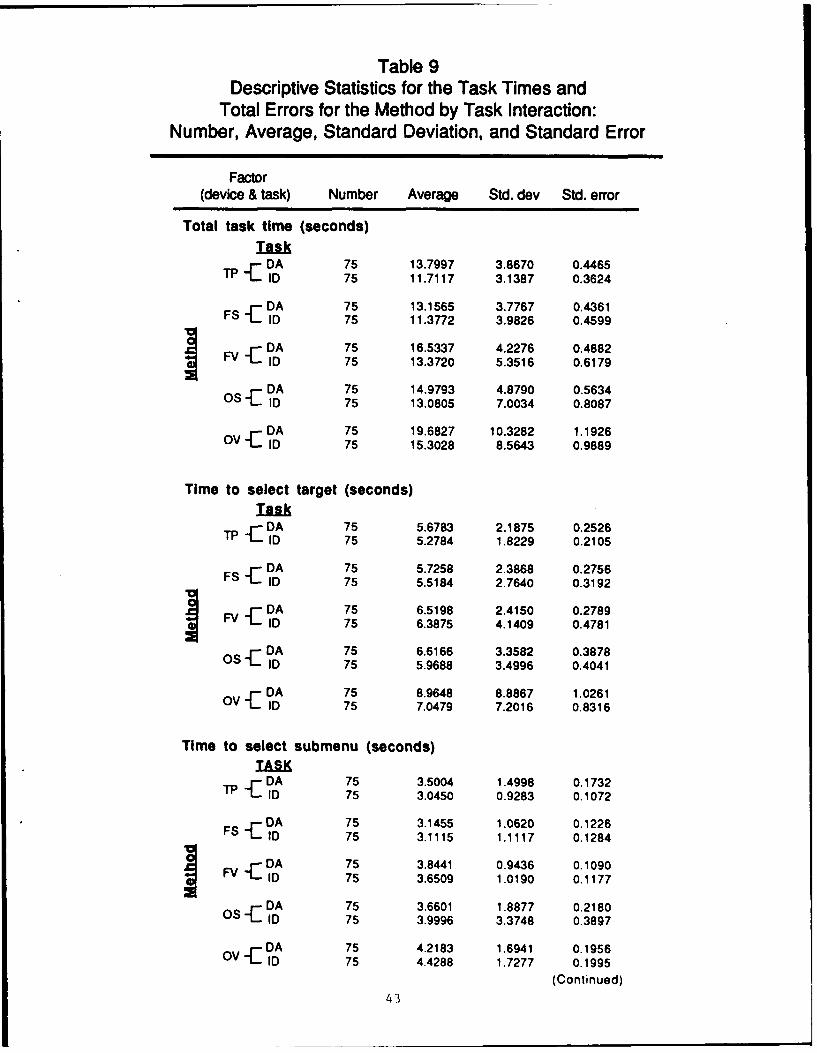
Table 9Descriptive Statistics for the Task Times and
Total Errors for the Method by Task Interaction:Number, Average, Standard Deviation, and Standard Error
Factor
(device & task) Number Average Std. dev Std. error
Total task time (seconds)Task
T DA 75 13.7997 3.8670 0.44651? ID 75 11.7117 3.1387 0.3624
F DA 75 13.1565 3.7767 0.4361FS ID 75 11.3772 3.9826 0.4599
FV DA 75 16.5337 4.2276 0.4882ID 75 13.3720 5.3516 0.6179
DA 75 14.9793 4.8790 0.5634OS - ID 75 13.0805 7.0034 0.8087
DA 75 19.6827 10.3282 1.1926OV ID 75 15.3028 8.5643 0.9889
Time to select target (seconds)Task
TP DA 75 5.6783 2.1875 0.2526ID 75 5.2784 1.8229 0.2105
DA 75 5.7258 2.3868 0.2756FS ID 75 5.5184 2.7640 0.3192
DA 75 6.5198 2.4150 0.2789FV ID 75 6.3875 4.1409 0.4781
OS DA 75 6.6166 3.3582 0.3878ID 75 5.9688 3.4996 0.4041
OV DA 75 8.9648 8.8867 1.0261ID 75 7.0479 7.2016 0.8316
Time to select submenu (seconds)TASK
Tf DA 75 3.5004 1.4998 0.1732TF ID 75 3.0450 0.9283 0.1072
DA 75 3.1455 1.0620 0.1226FS -ID 75 3.1115 1.1117 0.1284
FV DA 75 3.8441 0.9436 0.1090ID 75 3.6509 1.0190 0.1177
OS DA 75 3.6601 1.8877 0.2180ID 75 3.9996 3.3748 0.3897
OV DA 75 4.2183 1.6941 0.1956ID 75 4.4288 1.7277 0.1995(Continued)
43

Table 9 (Continued)
Factor(device & task) Number Average Std. dev Std. error
Time to complete subtask (seconds)
ImA"T -DA 75 4.6209 1.3169 0.1521
TP ".ID 75 3.3884 1.6958 0.1958
DA 75 4.2852 1.4042 0.1621FS "FID 75 2.7473 0.9455 0.1092
F -DA 75 6.1697 1.9702 0.2275F ID 75 3.3336 0.9295 0.1073
0 -DA 75 4.7025 1.4376 0.1660ID 75 3.1122 1.1047 0.1276
DA 75 6.4995 1.7047 0.1968OV -1ID 75 3.8261 1.9303 0.2229
Total errors
IaIkf- DA 75 0.0133 0.0000 0.0000
TP ID 75 0.0266 0.1622 0.0187
-DA 75 0.3333 0.6600 0.0762FS ID 75 0.2800 0.7035 0.0812
FV DA 75 0.2400 0.5123 0.0591ID 75 0.3333 0.7542 0.0871
DA 75 0.4667 0.9141 0.1055OS-C ID 75 0.4800 0.9981 0.1153
DA 75 0.7333 1.4079 0.1626OV-". ID 75 0.5733 1.1682 0.1349
KEY
TP -TOUCH PANEL
-F . XED RETICLE WITH VOICE ENTRY
! FS - FIXED RETICLE WITH SWITCH ENTRY
SOV - OCULOMETER WITH VOICE ENTRY
OS - OCULOMETER WITH SWITCH ENTRY
DA- ATA REQUEST
e-ID - IDENTIFICATION CHANGE
44
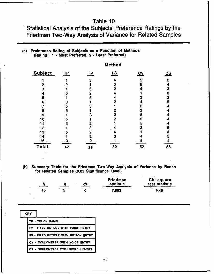
Table 10Statistical Analysis of the Subjects' Preference Ratings by theFriedman Two-Way Analysis of Variance for Related Samples
(a) Preference Rating of Subjects as a Function of Methods
(Rating: 1 - Most Preferred, 5 - Least Preferred)
Method
Subject TP FV FS OV OS
1 1 3 4 5 22 2 1 3 5 43 1 5 2 4 34 5 2 4 1 35 1 5 4 3 26 3 1 2 4 57 5 3 1 2 48 5 1 2 3 49 1 3 2 5 4
10 5 1 2 3 411 3 2 1 5 412 1 3 4 2 513 5 2 4 1 314 1 2 3 4 515 3 2 1 5 4
Total 42 36 39 52 56
(b) Summary Table for the Friedman Two-Way Analysis of Variance by Ranksfor Related Samples (0.05 Significance Level)
Friedman Chi-squareN k df statistic test statistic
15 5 4 7.893 9.49
KEY
TP - TOUCH PANEL
FV - FIXED RETICLE WITH VOICE ENTRY
FS - FIXED RETICLE WITH SWITCH ENTRY
OV - OCULOMETER WITH VOICE ENTRY
OS - OCULOMETER WITH SWITCH ENTRY
45

oculometer voice. The touch panel, oculometer switch, and reticle voice arestatistically grouped together. The switch methods are faster than the voice,and the fixed reticle is faster than the oculometer.
Task and Method Interactions
The results of the repeated measures analysis listed in Tables 5 and 6show that the task by method interaction is significant (0.05 confidencelevel) for the time to complete the submenu (T3). Figures 16 through 19 areplots of the average submenu times for each of the five methods performing thetwo tasks. The plot shows that the voice methods required longer than theswitch methods and the touch panel when performing the data request task (seeFigure 18); the performance was about the same for all the methods on theidentity specification task, however. The difference in times on the datarequest task is about 1.75 seconds. The subjects had to pause after readingthe requested data to the experimenter before voicing the "exit" command tothe speech recognizer. Since the recognizer processes connected speech butnot continuous speech, the pause was necessary to prevent running the twoutterances together.
Task Errors
The task errors are caused by the subjects selecting incorrect itemsinside the display capture window (see Methodology, Apparatus section), or bytrying to select display items outside the display window. The subject maymake these errors in one of two ways. First, he may make a cognitive mistakein selecting the wrong track or subtask in disagreement with the instruction.He then either completes the task erroneously or selects the "cancel" actionto start the task again. Another source of error is mechanical misalignmentof the selection point with the display item. The attempt to select a displayitem outside the display window will result in a hook action error if no otheritem is within the window. Again, the selection of a wrong display item maybe dropped with a cancel action to start the task again, or the subject mayerroneously process it to completion.
The results section shows that the total number of errors differsignificantly by method, but not by task or method and task interaction. Thedifferent types of errors made by the subjects are listed in Table 11 as"completed" errors and "selection" errors as a function of method. Completederrors are not corrected before the completion of the task. A selection erroris generated by any hook action exceeding the three selection actions requiredfor correct performance of the task, and by any cancel actions needed tocorrect erroneous hooking actions. These errors are a measure of thesubject's excessive activity in performing his task.
The total number of errors is 264 for the 750 test runs conducted in thisexperiment. On the average, this is one error every third test run. Thetotal number of errors are the sum of the number of completed errors and thenumber of selection errors.
Table 11 shows that very few completed errors were made. Most of the 31completed errors were caused by processing wrong tracks (24 errors). Threeerrors were caused by selecting the wrong track identification on the
46

= -i
ow
00> 0
_0 0J u.
W Lu
0 004
0 0
w~ >
0- 00
* 44
.1
00
-41
U'-
-4
(soes) eWi.
47

LL, 0W-u I-
0I>o
U.
0 W 0 0
I I)
ocn>00> -OOIfLLL>0.C', (A
0 '
w w.
.0
41
#E-
E4
(soes) ewij.
48

0 4 i
o ~
-'.
w. w
z wl-
I- W -
.1i>> m I w -)
1.- 0 0u
0 9)
w 4I0
0
>1
0.
494
00
0 co >J
0>-LU 0
Zti W w E=4
a. -dM
i 4-)
O X X <D
0 cc
o 0LIO 4-'
0 > 0 >j, 4
0 0
IL 0 Lw 0D
5- 0
--I
0 cD
>1
500

Table 11Statistical Analysis of Subject Errors by Error Type
(a) Number of subject errors by method and error type
Completed Errors Selection Errors
Method Track ID DA Task Hook Cancel
TP 0 1 1 0 1 0FV 1 0 0 0 32 10FS 7 0 2 0 31 8OV 8 0 1 0 71 19OS 8 2 0 0 49 12
Total 24 3 4 0 184 49
(b) Chi-square test of interaction between methods and error type:Contingency matrices
Observed ErrorsSelection
Method Hook Cancel Completed TotalFV 32 10 1 43FS 31 8 9 48OV 71 19 9 99OS 49 12 10 71
Total 183 49 29 261
Expected Errors
SelectionMethod Hook Cancel Completed
FV 30.15 8.07 4.78FS 33.66 9.01 5.33OV 69.41 18.59 11.00OS 49.78 13.33 7.89
Test value = 7.523
Chi-square statistic = 12.59
Confidence level = .05Degrees of freedom = 6
(Continued)
51

Table 11 (Continued)
(c) Chi-square test of total errors by type
SelectionHook Cancel Completed Total
Observed: 184 49 31 264
Expected: 87 87 87
Test value = 161.19
Chi-square statistic = 5.99
Confidence level = .05
Degrees of freedom = 2
K~EYITP - TOUCH PANEL
FV - FIXED RETICLE WITH VOICE ENTRY
FS - FIXED RETICLE WITH SWITCH ENTRY
OV - OCULOMETER WITH VOICE ENTRY
OS - OCULOMETER WITH SWITCH ENTRY
52

identification report task. Four errors were made by reporting the wrong dataon the data request task. No wrong tasks were completed.
A study of the selection error data listed in Table 11 suggests that theoculometer methods, and particularly the oculometer voice method, require muchmore activity than do the other methods to operate. In contrast, the touchpanel requires virtually no excessive activity. The fixed reticle with bothvoice or switch perform at about a level intermediate between the other twogroupings. The selection errors for the fixed reticle methods occur roughlyon the average once every fourth run. Those for the oculometer switch occuronce every 2-1/2 runs, while those for the oculometer voice occur once every1-1/2 runs. In all, 88.25% of the total errors were selection errors, and ofthese, 78.96% were hook action errors.
A nonparametric chi-square statistical test of the interaction betweenmethods and error types shows no significant interaction. The contingency.matrices are listed in Table 11 for both the observed errors and the expectederrors. The analysis is limited to the ocular methods. The touch panelerrors are too few to be included in a chi-square analysis since thecorresponding expected cell values are less than unity in violation of propertest conditions (Siegel, 1956). For the same reason, the different types ofcompleted errors are collapsed to a single column.
A large number of the errors are selection errors; about 90% of theerrors are of this type. A chi-square test shows significant difference (0.05confidence level) among the total errors for the hook selections, cancelselections, and completed errors (see Table 11). Table 12, which lists theselection errors as a function of subtask, shows that more than 80% of thehook selection errors occurred in the select menu subtask. Also, more than76% of the cancel selections occurred in the select menu subtask. The cancelselections during the select menu subtask are probably in response toerroneously hooked tracks in the track select subtask, however. The selectionof a track caused the display to automatically update from the track select tothe menu select. The 14% cancel selections in the track select subtask mightbe in response to the "error" message that followed hook actions of tracks notin the display selection window.
A nonparametric chi-square statistical test of the interaction betweenmethods and subtasks shows significant interaction for the hook selectionerrors. The contingency matrices are listed in Table 12 for both the observederrors and the expected errors. The analysis is limited to the ocularmethods. Again, the touch panel errors are too few to be included in a chi-square analysis since the corresponding expected cell values are less thanunity in violation of proper test conditions (Siegel, 1956). For the samereason, the data for the select submenu and complete submenu subtasks arecollapsed to a single column. A chi-square test shows significant difference(0.05 confidence level) among methods for the hook selection errors of thetrack select subtask (see Table 12). The implication is that significantlymore selection errors occurred with the oculometer voice method in the select-track subtask.
53

Table 12Statistical Analysis of the Selection Errors as a Function of Subtask
(a) Selection errors as a function of method and subtask
Hook Selection Errors
Select Select Complete CompleteMethod track submenu submenu task
TP 1 0 0 1FV 31 1 0 32FS 30 1 0 31OV .57 12 2 71OS 34 13 2 49
Total 153 27 4 184
Cancel Selections
Select Select Complete CompleteMethod track submenu submenu task
TP 0 0 0 0FV 3 7 0 10FS 0 7 1 8OV 3 13 3 19OS 1 10 1 12
Total 7 37 5 49
(b) Chi-square test of method by subtask Interaction for hook selection errors,Observed
Hook Selection ErrorsMethod Select-track Select-complete Total
FV 31 1 32FS 30 1 31OV 57 14 71OS 34 15 49
Total 152 31 183
ExpectedHook Selection Errors
Method Select-track Select-complete
FV 26.57 5.42FS 25.75 5.25OV 58.97 12.03OS 40.70 8.30
Test value - 15.37Chi-square = 7.82Significance level = 0.05Degrees of freedom = 3 (Continued)
54

Table 12 (Continued)
(c) Chi-square test of hook selection errors on track select subtask
Hook Selection ErrorsMethod
FV FS OV OS Total
Observed: 31 30 57 34 152Expected: 38 38 38 38
Test value = 12.89Chi-square statistic = 7.82Significance level = 0.05Degrees of freedom = 3
TP - TOUCH PANEL
FV - FIXED RETICLE WITH VOICE ENTRY
FS - FIXED RETICLE WITH SWITCH ENTRY
OV - OCULOMETER WITH VOICE ENTRY
OS - OCULOMETER WITH SWITCH ENTRY
55

Relation of Select-Track Subtask Times and Errors
Table 13 lists the number of runs for combinations of the select-tracksubtask times (seconds) and hook select errors for the different methods. Thetime is blocked in increments of 5 seconds to 30 seconds; the last column isfor task times greater than 30 seconds. Table 13 shows a uniform pattern from0 to 10 seconds for all runs with one or no errors. There is a scattering ofruns for larger errors and times beyond 10 to 15 seconds, however. This isespecially true of the oculometer voice method with a few runs longer than 30seconds and with five to six errors.
The computation of box plot outer fence values, which was derived withmedian-based exploratory data analysis techniques (Velleman & Hoaglin, 1983),shows that depending on the method, task times longer than 10 to 15 secondsmay be considered as distribution outliers. The correlation values for theconventional Pearson's linear correlation analysis of the times to errors for.the methods are listed in Table 13. The strongest correlation is for theoculometer voice method; the 0.7877 value indicates a high correlationcorresponding to a marked relationship. This is because of the few outliersof long task times and many errors. A review of the data shows that theseoutlier runs are well scattered among the subjects and not the product of onesubject or test sequence.
Sources of Selection Errors
The sources of selection errors for the ocular-based methods wereprobably (a) a slightly small display selection window, and (b) slight shiftsin boresight alignment from the calibration settings. The size of the displayselection window was determined from the published accuracies for theequipment (see Methodology, Apparatus, Display Selection Window section), andconfirmed in a pilot study. The listing in Table 13 shows that runs with oneselection error are intermixed with nonerror runs, however. This suggeststhat the selection window should have been slightly larger for the testpopulation. Test runs with two or more errors are mainly outliers possiblycaused by slight shifts in boresight alignment. While these explanations arespeculatively based on observations, two questions of interest are (a) what isthe cause of the misalignment, and (b) what is there about the oculometervoice method that causes the statistically significant increase in selectionerrors presumably associated with the misalignment? In this section of thereport, we review observations on the spatial tolerance needed to maintainalignment and possible causes of boresight misalignment.
The spatial tolerances required to operate the different methods aredetermined by the location accuracy of the devices comprising the method andthe effect of the subject's behavior on that accuracy. The accuracy of thespatial locating process for the fixed reticle methods is determined by theaccuracy of the Polhemus Isotrak and the accuracy with which the reticle maybe centered over the target image. The accuracy of the oculometer methods isdetermined by the accuracies of the Polhemus Isotrak and the NAC oculometer.These accuracies and the constraints on operation are covered in theMethodology, Apparatus section, and the Training and Test Procedures section.As noted in the Training and Test Procedures section, slight changes in facial
56

Table 13Statistical Analysis of the Relationship Between the
Times and Errors of the Select-Track Subtask
(a) Number of runs by task time and hook select errors for select-track subtask ofeach method
Number Subtask Time (seconds)Method errors 0-5 5-10 10-15 15-20 20-25 25-30 30+
0 68 51 1 a 0 0 0 0TP 1 4 18 5 1 0 0 0
2 0 0 2 0 0 0 0
0 48 72 Ob 0 0 0 0FV 1 2 20 2 4 1 0 0
2 0 0 0 0 0 1 00 74 48 2c 0 0 0 0
FS 1 4 12 5 0 1 0 02 0 1 3 0 0 0 00 41 75 1 d 0 0 0 01 0 14 8 1 0 0 0
Ov 2 0 0 0 2 2 0 03 0 0 1 0 0 1 04 0 0 0 0 0 1 05 0 0 0 0 0 0 26 0 0 0 0 0 0 10 62 56 3e 1 0 0 0
OS 1 2 14 4 1 1 0 02 0 0 3 2 1 0 0
Note: Outer fence values for exploratory data analysis box plots:a- 10-.39, b- 13.59, c- 12.44, d- 15.04, e- 13.48.
(b) Correlation of number of hook selection errors and task time for the select-tracksubtask of each method
Method CorrelationTP 0.3602FV 0.3759FS 0.3351OV 0.7877OS 0.4636
KEY
TP - TOUCH PANEL
FV - FIXED RETICLE WITH VOICE ENTRY
FS - FIXED RETICLE WITH SWITCH ENTRY
OV - OCULOMETER WITH VOICE ENTRY
OS - OCULOMETER WITH SWITCH ENTRY
57

expressions and head movements can cause a shift in the position of theoculometer mask on the face. A 0.1-millimeter shift in mask position willcause a 1.40 shift in boresight (NAC, 1987).
Another influence on spatial accuracy is the behavior of the subjectswhen operating the different data entry methods. Some subjects pushed thedata entry switch with such vigor that the reaction along the mechanicallinkage between their hands and shoulders would cause a shift in the positionof their heads. A change in switch type (toggle versus pressure) and positionmay correct this problem.
A source of error for the oculometer voice method may be the 1/2-seconddelay in verbalizing the voice command and processing by the automatic speechrecognizer. Shifting attention from the visual modality to the auditoryduring this time may allow a slight relaxing of the head position.Furthermore, the head may tend to shift as the subject expels air from thelungs when voicing the verbal command. The changes in facial muscles withspeech generation may also cause slight shifts in the mask on the face. Onesolution may be to keep a running record of previous gaze points and extractbackward to the time the utterance began, using an utterance start-detectioncircuit interfaced to the computer.
In contrast, the fixed reticle and voice method incorporates a visualalignment task with definite visual cues and feedback from the reticle. Inthis case, the subject's attention may be time-shared between the visual andauditory modalities, and the 1/2-second delay in processing the verbalizationwould not generate head relaxation with the associated selection errors.
As they made a button push or verbal command, some subjects tended toshift their gaze to the next part of the task before completing contact. Thesubjects had to be instructed to hold their gaze until display-generatedfeedback showed that the selected action had been implemented. A fastersampling rate and maintaining a running record of previous gaze positionscoupled with a backward --iction may afford a quicker and more flexiblesystem. It is doubtful that the gaze and decision times are constants, andthe implementation of such a scheme may generate erroneous selections.
Speech Recognizer Errors
The performance of the automatic speech recognizer was greater than99.44%; it was not a source of error in operating the fixed reticle oroculometer with voice. In this test, only five nonrecognition errors weremade with the automatic speech recognizer by 3 subjects of the 15. Allnonrecognitions were made with the oculometer voice method. No incorrectrepresentations or substitutions occurred. The performance of the speechrecognizer was better than 99.44% since more than 900 voice command entrieswere made during the test. A check of the nonerror task times for theoculometer voice method shows no noticeable change when the times of thecorresponding five test runs are adjusted for nonrecognitions.
The high accuracy of the speech recognizer was attained by the choicc ofonly two command words (i.e., hook and cancel) with different spectralcontents, and the setting of the reject threshold to 17, an extremely lowvalue. The recognition score was typically in the 30 to 40 value range.
58

This level of recognizer performance has not been attained in previousexperiments (Smyth, Denny, & Dotson, 1987) in which the recognizer was usedalone with many command choices. The use of the recognizer with theoculometer or fixed reticle allows the work load to be divided among thedifferent modalities of sight and voice, thereby reducing the word templatesrequired and consequently increasing the performance of the recognizer.
Dropped Subjects
While 15 subjects completed the test, 20 subjects started thisexperiment. The remaining five subjects were dropped from the test for thefollowing reasons. Two subjects had extremely erratic eye movement patternsand were not able to hold their eye gaze steady long enough to be calibratedwith the oculometer. One subject was a 17-year-old enlisted soldier who saidthat he got little sleep at night. Essentially, his eyes were in a continualsearch pattern. The other subject was 25 years old. His eye movementpatterns were more controlled but not enough to allow calibration.
Two subjects elected to discontinue the test before completion becauseof discomfort and fatigue. One of the uncontrolled factors in this test wasthe tightness of the head band on the oculometer head support system (seeFigures 1 and 2) used to maintain a fixed alignment on the head. Furthermore,the 1.6 pounds (720 grams) weight of the Eyemark are loaded to the front ofthe mask, and the uneven distribution places a strain on the user's neckmuscles. Finally, the visual attention demanded by the forced gaze, requiredto operate the oculometer as a pointing device, is known to reduce eye blinksand thereby dry the corneas of the eyes causing ocular fatigue. Most subjectslearned with practice to tolerate these discomforts, however.
The fifth subject could not complete the test because of computerequipment breakdown caused by failure of the controller board on the VAX11/780.
Nonerror Task Times
A question of interest is the effect that the error runs had on thestatistical results for the task times. Table 14 lists the differencesbetween the average task times for the error-free runs and all runs of eachsubtask and the total task for each method and task combination. The tablelists also the nonparametric sign test for the case of two related samples.The results show that there is a significant difference (0.05 confidencelevel) between the average error-free and all data times for the total tasktimes and the subtask times except for the subtask to complete the menuaction.
Since the differences between the average error-free and the all dataruns are statistically significant, the next question is whether there is asignificant difference among the nonerror task times for the differentmethods, and if so, what is the corresponding ranking? In other words, is thestatistically significant difference among the all data times for the methodsa result of the errors alone? Table 15 lists the results of a nonparametricFriedman two-way statistical analysis of variance by ranks for related
59

Table 14Statistical Analyses of the Difference Between the Average Times for
Error-Free Runs and Total Runs
(a) Differences between average times (seconds) for the error-free runs andtotal runs for method and task
Su btaskSelect Select Complete Complete
Task Method track menu menu task
ID TP -.0249 -.0021 -.0026 -.0297FS -.7554 -.1131 -.0419 -.9109FV -1.2623 -.1176 -.0371 -1.4173Os -.8805 -.6785 -.1876 -1.6658OV -1.4181 -.4282 -.3193 -2.1658
DA TP 0.0074 -.0257 0.0173 -.0009FS -.4500 0.0703 0.0103 -.3699FV -.6015 -.0205 -.0739 -.6964OIS -1.3821 -.4236 -.1876 -1.9944OV -3.0259 -.3097 0.0155 -3.3141
(b) Nonparametric sign test for two related samples applied to the differencedata
SubtaskSelect Select Complete Complete
Task Method track menu menu taskID TP-
FS-FV-
Ov-
DA TP+ +
FS -+ +FV-
Ov + -
Sign changes 1 1 3 0Probability 0.011 0.011 0.172 0.001
KEYTP - TOUCH PANEL
0 FV - FIXED RETICL.E NiTH VOICE ENTRY
$2FS - FIXED RETICLE WITH SWITCH ENTRY
*OV - OCULOMETER WITH VOICE ENTRY
OS - OCULOMETER WITH SWITCH ENTRY
SDA-.DATA REQUIEST
10 - IDENTIFICATION CHANGE
60

Table 15Statistical Analysis of the Error-Free Times
(a) Average times for the error-free runs by method and task
SubtaskSelect Select Complete Complete
Task Method Number track menu menu task
ID TP 73 5.2359 3.0428 3.3859 11.6830FS 61 4.7633 2.9988 2.7052 10.4651FV 59 5.1261 3.5338 3.2970 11.9545OS 53 5.0882 3.3214 3.0039 11.4119OV 49 5.6271 4.0004 3.5070 13.1334
............................................ ... ................. ...o.. .... .......... .................... ....... .= ....... ................. ................... ,o ..... ....... ° ... ........... ........... ,.....
DA TP 74 5.6857 3.4751 4.6381 13.7981FS 56 5.2758 3.2157 4.2958 12.7861FV 60 5.9179 3.8240 6.0959 15.8382OS 53 5.2346 3.2365 4.5152 12.9837OV 52 5.9412 3.9089 6.5165 16.3646
(b) Friedman two-way analysis of variance by ranks for related samples ofthe error-free times
MethodSubtask Task TP FS FV OS OV
Select track ID 4 1 3 2 5DA 3 2 4 1 5
Select menu ID 2 1 4 3 5DA 3 1 4 2 5
Complete menu ID 4 1 3 2 5DA 3 1 4 2 5
Complete task ID 3 1 4 2 5DA 3 1 4 2 5
Total 25 9 30 16 40
Friedman test value = 29.1Chi-square statistic = 9.49Confidence level = .05Degrees of freedom = 4
1?.- TOUCH PANEL
.FV- FXED RETICLE WITH VOICE ENTRY
FS - FIXED RETICLE WITH SWITCH ENTRY
3 OV - OCULOMETER WITH VOICE ENTRY
ETERWITH SWITCH ENTRY
DA - DATA REUEST
SID - IDENTIFICATION CHANGE
-6---- ---

samples. The table lists the average task times for the error-free runs bymethod and subtask and total task for each task. Table 15 also lists theranking of the times for each method. The difference among the methodsremains statistically significant (0.05 confidence level); the rankingscontinue to agree with the parametric analysis of all the data times reportedin the Results section. This result implies that the time differences arebecause of the different methods.
Nonerror Spatial Tolerance
Table 16 lists the descriptive statistics for the spatial tolerancerequired to operate the different methods in the track selection subtask forthe nonerror trials. The statistics are the number of nonerror trials, theaverage displacement of the computed selection point from the selected displayitem, the minimum and maximum displacements, and the standard deviation. Theselection point for the touch panel is the point where the subject touched thescreen. The selection point for the remaining methods is the computed gazepoint on the display. The average, minimum, and maximum are the appropriatestatistics for the displacement of the subject's touchpoint or computed gazepoint from the center of the selected track symbol. The standard deviation isthat of the displacements about the center of the selected display item. Themaximum value listed in Table 16 is used as an estimate of the toleranceneeded to operate the method.
The track symbol for the track selection subtask is a small target (.228in. 2 ) subtending 25 minutes of arc at the viewer's eye. The display isnormal to the viewing direction. The viewing distance is about 27 inches.Table 16 lists the statistics for both inches of displacement on the displaysurface and the equivalent angular displacement in degrees. The concept of anangular accuracy for the touch panel as measured from the viewpoint isoperationally meaningless but is included for comparison to the ocular-basedmethods.
An interpretation of the data listed in Table 16 is that for the trackselection subtask, the touch panel requires half the tolerance required forthe other devices. The tolerances required for the other devices are aboutthe same value. The tolerance of the touch panel is about +1/2 inch (±10).The tolerance of the remaining devices is about ±1.1 inches (±2.40).
The computed tolerance of the ocular-based methods is about half the sizeof the display window and the actual required tolerance may be larger. Theattempt to select track symbols outside the display window would be registeredas selection errors.
Table 17 lists the frequency distribution for the spatial tolerance ofeach method. The table lists the midpoints for the spatial tolerance rangesof the eight cells from 0.0 inch to 1.384 inches and the correspondingfrequencies for each spatial cell. Figure 20 is a frequency plot of the datalisted in the table.
The frequency plot for the spatial tolerance of the touch panel is wellwithin the limits of the display selection window (±1.1 in.). In contrast,the distribution plots for the ocular methods are much wider. The plots forthe switch methods are certainly skewed and possibly bimodal with the larger
62

Table 16Descriptive Statistics for the Spatial Tolerance of the
Track Selection Subtask Number, Average, Minimum (MIN),Maximum (MAX), and Standard Deviation (SD)
I. Display tolerance (Inches)
Method Number Average MIN MAX SD
TP 107 0.219 0.011 0.553 0.249FV 117 0.502 0.014 1.115 0.554FS 114 0.521 0.085 1.148 0.579OV 88 0.516 0.076 1.226 0.584OS 99 0.520 0.085 1.031 0.566
I1. Angular tolerance (degrees)
Method Number Average MIN MAX SD
TP 107 0.464 0.022 1.173 0.528FV 117 1.066 0.029 2.365 1.175FS 114 1.105 0.181 2.435 1.229OV 88 1.096 0.161 2.600 1.240OS 99 1.103 0.181 2.187 1.202
HEY]
TP - TOUCH PANEL
FV - FIXED RETICLE WITH VOICE ENTRY
FS - FIXED RETICLE WITH SWITCH ENTRY
OV - OCULOMETER WITH VOICE ENTRY
OS - OCULOMETER WITH SWITCH ENTRY
63

Table 17Frequency Distribution of the Spatial Tolerance of Each Method
Spatial Tolerance (Inches)
Method Runs 0.081 0.254 0.427 0.601 0.773 0.946 1.119 1.292
TP 107 .411 .439 .140 .009 .000 .000 .000 .000FV 117 .086 .179 .274 .248 .154 .043 .017 .000FS 114 .079 .193 .272 .237 .088 .096 .035 .000OV 88 .114 .171 .239 .204 .148 .079 .028 .028OS 99 .061 .152 .263 .333 .101 .091 .000 .000
LKEYTP - TOUCH PANEL
FV - FIXED RETICLE WITH VOICE ENTRY
FS - FIXED RETICLE WITH SWITCH ENTRY
OV - OCULOMETER WITH VOICE ENTRY
OS - OCULOMETER WITH SWITCH ENTRY
64

owt () 0
U) >
> j-WWWW t)
.0
-i _j
D~o>o w
00-Oo~rL w
ol
> Z 4< 4)
U.- m 00O -J (a0
4)
CL '
r-4
CY
In; C;I
(1N338d) AO3n~fO3U~
65
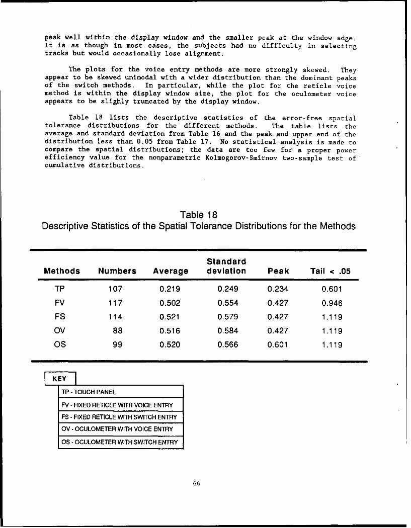
peak well within the display window and the smaller peak at the window edge.It is as though in most cases, the subjects had no difficulty in selectingtracks but would occasionally lose alignment.
The plots for the voice entry methods are more strongly skewed. Theyappear to be skewed unimodal with a wider distribution than the dominant peaksof the switch methods. In particular, while the plot for the reticle voicemethod is within the display window size, the plot for the oculometer voiceappears to be slighly truncated by the display window.
Table 18 lists the descriptive statistics of the error-free spatialtolerance distributions for the different methods. The table lists theaverage and standard deviation from Table 16 and the peak and upper end of thedistribution less than 0.05 from Table 17. No statistical analysis is made tocompare the spatial distributions; the data are too few for a proper powerefficiency value for the nonparametric Kolmogorov-Smirnov two-sample test ofcumulative distributions.
Table 18Descriptive Statistics of the Spatial Tolerance Distributions for the Methods
Standard
Methods Numbers Average deviation Peak Tail < .05
TP 107 0.219 0.249 0.234 0.601
FV 117 0.502 0.554 0.427 0.946
FS 114 0.521 0.579 0.427 1.119
OV 88 0.516 0.584 0.427 1.119
OS 99 0.520 0.566 0.601 1.119
SKEYITP - TOUCH PANEL
FV - FIXED RETICLE WITH VOICE ENTRY
FS - FIXED RETICLE WITH SWITCH ENTRY
OV - OCULOMETER WITH VOICE ENTRY
OS - OCULOMETER WITH SWITCH ENTRY
66

CONCLUSIONS
The results of this experiment suggest that the ocular-based gazepointing methods are more inaccurate and no faster than the touch panel forselection of displayed data items in simple primary tasks involving displayinteractions. The touch panel and the switch-based methods are significantlyfaster than the voice entry methods. The head-fixed reticle methods arefaster than the oculometer methods of the same modality. The gaze pointingmethods require a larger display selection window than is required for thetouch panel. This is especially true for the oculometer voice method whichgenerated significantly more selection errors than the other methods,suggesting that the oculometer voice method is more inaccurate than the othermethods. The ocular-based gaze pointing methods may be acceptable as a meansof interacting with a display for secondary discrete tasks during flying whenonly a few widely spaced selections are displayed on the screen at one time.
RECOMMENDATIONS FOR FURTHER RESEARCH
The use of the ocular-based gaze pointing methods with properly designeddisplays may allow the display interaction part of the pilot's work load to beseparated into a sequence of short discrete steps. These may cause minimalinterference with the continual tracking task component used to pilot ahelicopter. The pilot would interact with the displays through a few, widelyspaced menu options which he would select with a momentary eye gaze and buttonpush or voice command. Alternately, he could use a sequence of switch actionsto index to the data item of interest within a display selection windowcentered by an initial eye gaze. For this reason, further research into theuse of eye gaze techniques for display and instrument control is recommendedas follows:
1. Better equipment is needed for further investigation, includinga lighter, more accurate, and stable head-held oculometer and a fastercomputer processing system.
2. Investigate the use of responses from intrinsic variables toreplace switches or voice entry as methods to select display items. Thevariables could include eye dwell time, pupil dilation, eye blinks, andElectroencephalograms (EEC). The processing of these signals may allow a morenatural and quicker response freeing the manual modality in helicopters forpiloting.
3. Investigate helicopter display formats appropriate for thereduced spatial accuracy of ocular-based gaze pointing methods. The use ofwidely separated menu tree selections could be used with a sequence ofchoices. Another approach would a sequential hook mechanism using a three-waytoggle switch with positions for initialization, selection, and confirmation.The first switch action would center a selection window at the gaze point andthe remaining actions would index the hooking among the track symbols withinthe window until a confirmation switch action is made.
67
4. Investigate the change in work load caused by the increase invisual loading associated with the use of such devices. The necessity ofdirected gazes decreases eye blinks while increasing ocular fatigue.
5. Investigate the integration of an ocular-based gaze pointingmethod with helmet-mounted displays (HMD). In particular, can a fixed reticledisplayed on a HMD be used to interact with panel-mounted displays?Alternately, does the addition of an oculometer to a helmet allow interactionwith HMDs? How can the processing system be designed to distinguish betweenthe selection of a data item on the HMD ocular display and that of an externaltarget when the pilot is operating in a heads-up mode?
6. Investigate the effects of the operational environment withnatural sunlight and the vibrations induced in a moving helicopter on theperformance of an oculometer-based system.
68

REFERENCES
Billingsley, P. A. (1982). Navigation through hierarchical menustructures: Does it help to have a map? Proceedings of the HumanFactors Society 26th Annual Meeting, 103-107.
Breglia, D. R. (1981). Helmet Mounted Eye Tracker Using a Position SensingDetector, PAT-APPL-6-262 153 (Patent Application), Washington, DC:Department of the Navy.
Department of Defense. (1981, May). Military Standard on HumanEngineering Design Criteria for Military Systems. Equipment andFacilities (MIL-STD-1472C). Washington, DC: U.S. Government PrintingOffice.
Department of Defense. (1983, May). Military Standard on Symbols for ArmyAir System Displays (DoD-STD-1477 [MI]). Washington, DC: U.S.Government Printing Office.
Fallesen, J. J., Smyth, C. C., & Blackmer, R. F. (1983). Human EngineeringLaboratory Division Air Defense Systems-I (HELDADS-I): Baseline AirBattle Management Operations Center (ABMOC) Manual Performance(Technical Memorandum 11-83). Aberdeen Proving Ground, MD: U.S. HumanEngineering Laboratory.
List, Uwe H. (1983). Nonlinear prediction of head movements for helmet-mounted displays (AFHRL-TP-83-45). Williams Air Force Base, AZ:Operations Training Division, Air Force Human Resources Laboratory.
Meyer, A. U. (1981). Dynamics of two-dimensional eye-head tracking (AFOSR-TR-81-0610). Newark, NJ: Department of Electrical Engineering,Institute of Technology.
Miller, D. P. (1981). The depth/breadth tradeoff in hierarchical computermenus. Proceedings of the Human Factors Society 25th Annual Meeting,542-546.
NAC, Inc. (1987). Operational manual: Eye Mark Recorder (Model V). NAG,Incorporated.
Setterholm, J. M. (1982). Assessment of stereo-graphics for fire controland navigation in fighter aircraft (AFWAL-TR-82-3008). Minneapolis, MN:Honeywell, Incorporated.
Siegel, S. (1956). Non-parametric statistics for the behavior sciences,New York, NY: McGraw-Hill Book Company.
Smyth, C. C., Denny, S. M., & Dotson, D. D. (1987). Comparison of voicerecognition, touch panel, and keypad techniques of data entry for aforward area air defense command, control, and intelligence (FAAD C_ I)display (Technical Memorandum 25-87). Aberdeen Proving Ground, MD:U.S. Army Human Engineering Laboratory.
69

70

APPENDIX
POSTTEST QUESTIONNAIRE AND RESULTS
71

72

POSTTEST QUESTIONNAIRE
1. How would you rank the five hooking test procedures?
The combinations were
a. Fixed Reticle Search with Switch Inputb. Fixed Reticle Search with Voice Inputc. Oculometer Search with Switch Inputd. Oculometer Search with Voice Inpute. Touch Panel
Rank Combination
1
2345
2. Why did you like 1 the best?
3. Why did you like 5 the least?
4. Do you have any suggestions for improvements?
Overall-
Oculometer related-
Fixed Reticle related-
Data Input Methods-
Switch-
Voice-
Touch Panel-
5. What is your overall opinion of the experiment?
6. Do you have any suggestions for further research?
73

7. What is your opinion of the concept of the fixed reticle, the oculometer,and the touch panel regardless of the equipment used?
8. What improvements (in the equipment or procedure) do you feel would berequired in order to make the concept of these methods more attractive?
74

QUESTIONNAIRE RESULTS
General problems and suggestions for improvements were noted in thesubjects' questionnaires, as follow:
1. HELMET
Suggestions:
- Need a better fitting helmet to reduce fatigue and pain- Lighten helmet- Need better helmet adjustability- Make mask part bigger - eliminate closed in feeling- Need to work on better head gear
2. OCULOMETER
Suggestions:
- Should be able to move your head, too fatiguing to hold itstill
- Use a head brace to relieve muscle fatigue- Oculometer should be calibrated by the operator- Should have a better balanced head set- Get rid of helmet and find another method or make helmet
comfortable
3. FIXED RETICLE
Problems:
- Reticle was too difficult to see- Had trouble adjusting eye focus on target and reticle overlay- Had trouble seeing reticle with both eyes open
Suggestions:
- Reticle should be projected to infinity and sharper image- Reticle should be thinner- Illuminate the reticle- Replace cross hairs with a dot- Use a larger reticle and adjust it to individual's focal point
75
4. SWITCH
Suggestions:
- Make switches more sensitive- Get better switches- Use hand-held switches
5. VOICE INTERACTION
Suggestions:
- Improve voice recognition given stress- Improve voice recognition given voice inflection
6. TOUCH PANEL
Problem:
- Too cumbersome and slow
Suggestions:
- Use a soft touch switch panel- Improve touch panel so pencil need not be put straight
in and out- Use finger to touch
76

Table 1Cross Tabulation Table for Subjects' Rating of Preference
Configurations
TP FV FS OV OS
S1,S3,S5, S2,$6,S8 S7, S11 & S15 S4 & S13 None
1 9, S12 & & S10
814"o
~0a_
. 82 S4, S11 ,13. $3,$6,S8 S7 & S12 S1 & S5
$) 2 S14 &15 S9 & S10.J
a)-
S6, S11 & S15 $1,$7,$9 S2 & S14 S5, $8 & S10 S3, S4 & S13S 3 & $12
C.
'IA02 None None S1 84, 5, 83. S6 & S14 82, S7, 88,
4 812 & S13 89, 10, 811
& S15
-4,7,8, S3 & S5 None $1,$2,89, S6, 12 & S14
5 S10 & S13 S11 & 815
TP -TOUCH PANEL
FV -FIXED RETICLE WITH VOICE ENTRY
FS -FIXED RETICLE WITH SWITCH ENTRY
OV -OCULOMETER WITH VOICE ENTRY
OS -OCULOMETER WITH SWITCH ENTRY
77