DT|C · DT|C Richard A. Voipet Pradeep K. Khosla 1EC ' 993 CMU-RI-TR-93-11 Advanced Manipulators...
28
o Technical Report Design of Dynamically Reconfigurable "o Real-Time Software using Port-Based Objects David B. Stewart Richard A. Voipet DT|C Pradeep K. Khosla 1EC ' 993 CMU-RI-TR-93-11 Advanced Manipulators Laboratory, The Robotics Institute, and Department of Electrical and Computer Engineering Carnegie Mellon University 5000 Forbes Avenue I oc Pittsburgh, PA 15213 ,ItZUti~ July 1, 1993 a 1993 Carnegie Mellon Unviersity The research reported in this paper is supported, in part by, U.S. Army AMCOM and DARPA under contract DAAA- 2189-C-O000, the National Aeronautics and Space Administration (NASA) under contract NAG1-1075, the Depart- "ment of Electrical and Computer Engineering, and by The Robotics Institute at Carnegie Mellon University. Partial support for David B. Stewart is provided by the Natural Sciences and Engineering Research Council of Canada (NSERC) through a Graduate Scholarship. Part of the research reported in this paper was also performed for the Jet Propulsion Laboratory (JPL), California Institute of Technology, for the Remote Surface Inspection system develop- ment and accompanying projects under a contract with NASA. Reference herein to any specific commercial product, process, or service by trade name, trademark, manufacturer, or otherwise, does not constitute or imply its endorsement by the United States Government or JPL. t R. Volpe is at the Jet Propulsion Laboratory, California Instihtte of Technology, Pasadena, California. 93 12 16 045 93-30563 I liii Ii
Transcript of DT|C · DT|C Richard A. Voipet Pradeep K. Khosla 1EC ' 993 CMU-RI-TR-93-11 Advanced Manipulators...

o Technical Report
Design of Dynamically Reconfigurable"o Real-Time Software using Port-Based Objects
David B. StewartRichard A. Voipet
DT|C Pradeep K. Khosla
1EC ' 993 CMU-RI-TR-93-11
Advanced Manipulators Laboratory, The Robotics Institute, andDepartment of Electrical and Computer Engineering
Carnegie Mellon University5000 Forbes Avenue
I oc Pittsburgh, PA 15213,ItZUti~ July 1, 1993
a 1993 Carnegie Mellon Unviersity
The research reported in this paper is supported, in part by, U.S. Army AMCOM and DARPA under contract DAAA-
2189-C-O000, the National Aeronautics and Space Administration (NASA) under contract NAG1-1075, the Depart-"ment of Electrical and Computer Engineering, and by The Robotics Institute at Carnegie Mellon University. Partialsupport for David B. Stewart is provided by the Natural Sciences and Engineering Research Council of Canada(NSERC) through a Graduate Scholarship. Part of the research reported in this paper was also performed for the JetPropulsion Laboratory (JPL), California Institute of Technology, for the Remote Surface Inspection system develop-ment and accompanying projects under a contract with NASA. Reference herein to any specific commercial product,process, or service by trade name, trademark, manufacturer, or otherwise, does not constitute or imply its endorsementby the United States Government or JPL.
t R. Volpe is at the Jet Propulsion Laboratory, California Instihtte of Technology, Pasadena, California.
93 12 16 045 93-30563I liii Ii

Abstract
The current development of applications for sensor-based robotic and automation (R&A) systems is typi-cally a "one-of-a-kind" process, where most software is developed from scratch, even though much of thecode is similar to code written for other applications. The cost of these systems can be drastically reducedand the capability of these systems improved by providing a suitable software framework for all R&A sys-tems. We describe a novel software framework, based on the notion of dynamically reconfigurable softwarefor sensor-based control systems. Tools to support the implementation of this framework have been builtinto the Chimera 3.0 Real-Time Operating System. The framework provides for the systematic developmentand predictable execution of flexible R&A applications while maintaining the ability to reuse code from pre-vious applications. It combines object-oriented design of software with port-automaton design of digitalcontrol systems. A control module is an instance of a class of port-based objects. A task set is formed byintegrating objects from a module library to form a specific configuration. An implementation using globalstate variables for the automatic integration of port-based objects is presented. A control subsystem is a col-lection of jobs which are executed one at a time, and can be programmed by a user. Multiple control sub-systems can execute in parallel, and operate either independently or cooperatively. One of the fundamentalconcepts of reconfigurable software design is that modules are developed independent of the target hard-ware. Our framework defines classes of reconfigurable device driver objects for proving hardware indepen-dence to I/O devices, sensors, actuators, and special purpose processors. Hardware independent real-timecommunication mechanisms for inter-subsystem communication are also described. Along with providinga foundation for design of dynamically reconfigurable real-time software, we are also developing manymodules for the control module, device driver, and subroutine libraries. As the libraries continue to grow,they will form the basis of code that can eventually be used by future R&A applications. There will no long-er be a need for developing software from scratch for new applications, since many required modules willalready be available in one of the libraries.
Accesion For
NTIS CRA& L
DTIC iPJ3Unannou;,:cdJustification ...............................
By .. ..... S'SDist ~ution 4 .. ..... I.............
Availab,.-.y "%Aes
Avail a! 'I OrDist Spuciat
,r I

Table of Contents
1. Introduction ......... .......................................... 1
2. Motivation ................................................... 2
3. Term inology ........... ......................... .. .... 3
4. Description of a Software Framework for Reconfigurable Systems ................ 64.1. Port-Based Objects ........................................ 74.2. Control Module Integration .................................... 84.3. Generic Framework of a Port-Based Object ......................... 114.4. Reusing and Reconfiguring Modules ............................. 154.5. Combining Objects ........................................ 164.6. Hardware Independent Interfaces ................................ 16
4.6.1. Reconfigurable I/O Device Drivers ........................ 174.6.2. Sensor-Actuator Interface and Drivers ...................... 184.6.3. Special Purpose Processor Interface and Drivers ............... 19
5. Systems Integration .............................................. 195.1. Aperiodic Communication ................................... 195.2. Periodic Communication .................................... 20
6. Future Work .................................................. 21
7. Acknowledgments .............................................. 22
8. References ................................................... 23

List of Figures
Figure 1: Reusable software control modules within a reconfigurable system ........... 2
Figure 2: Software framework for reconfigurable systems ...................... 4Figure 3: Typical target hardware for a reconfigurable sensor-based control system ....... 6Figure 4: Simple model of a port-based object, also called a control module ........... 7Figure 5: Fanning an output into multiple inputs ............................ 7Figure 6: Joining multiple outputs into a single input ........................... 8Figure 7: Sample control module library ....... ............................ 9Figure 8: Example of PD) joint control .................................... 9
Figure 9: Structure of state variable table mechanism for control module integration ..... .10Figure 10: Example of module integration: Cartesian teleoperation ................ 12Figure 11: Generic framework of a port-based object .......................... 13Figure 12: Example of visual servoing using inverse dynamics control module ........ .15
Figure 13: Example of visual servoing using damped least squares control module ...... .15Figure 14: Example of combining modules: a computed torque controller ........... .17Figure 15: Flowchart of the sender and receiver tasks for triple-buffered communication . . . 21

1 Introduction
The current development of applications for sensor-based robotic and automation (R&A) systems is typi-cally a "one-of-a-kind" process, where most software is developed from scratch, even though much of thecode is similar to code written for other applications. A high level of expertise is required to program anduse these systems: both the programmer and user must have combined experience in sensor-based controlsystems theory, mechanics of manipulators, software engineering, real-time systems theory, operating sys-tems programming, writing device drivers, and possibly other specialty areas depending on the application.The end result is a significant investment in software development, maintenance, and operating costs.
The cost of these systems can be drastically reduced and the capability of these systems improved by pro-viding a suitable software framework for all R&A systems. The framework should provide an infrastructurefor the programmer. It should include guidelines for decomposing applications into modules, methods forusing modules from previous applications with minimal code modification, and specifications for moduleand communication interfaces. The infrastructure should also provide software tools for directly implement-ing an application based on familiar abstractions, automatically integrating the software modules, and en-suring predictable execution of the real-time code. The framework must be targeted to those people whowill actually program and use the systems, which are the control engineers and shop floor workers respec-tively, and not software engineers or computer scientists.
Predictable execution of robotic applications has been addressed by Lyons et al. [10]. They use robot sche-mas based on port-automaton theory [171 to model computational aspects of robot execution, and provide away of analyzing these models for real-time execution. This method provides systematic development ofone-of-a-kind applications, but does not provide any means for reusing code from previous applications.
A popular method for improving code reusability is to use object-oriented design [3]. This methodology wasadopted for robotic applications in the Robot Independent Programming Environment (RIPE) [121. RIPEuses object-oriented design for planning and programming of robotics applications. RIPE, however, doesnot make any specifications for the underlying real-time code. Object-oriented design of real-time systemshas been addressed by the Chaos system [15], which provides real-time support for objects. However, asdiscussed in [2] they have been unable to provide suitable real-time dynamic creation and destruction of ob-jects nor predictable inter-object communication, both of which are required in flexible R&A systems.
In this paper, we describe a novel software framework, based on the notion of dynamically reconfigurablesoftware for sensor-based control systems. It provides for the systematic development and predictable exe-cution of flexible R&A applications while maintaining the ability to reuse code from previous applications.The framework combines object-oriented design of software with port-automaton design of digital controlsystems. The object-oriented methodology is used to provide a general framework for reusing code fromprevious applications and for providing hardware independent interfaces to specialized hardware, while theport-automaton methodology is used to provide automatic integration, real-time communication, and dy-namic reconfiguration of task sets within an application. From this combination, we introduce the notion ofport-based objects, which are objects that have input and output ports for real-time inter-object communi-cation, and resource ports for communication with sensors, actuators, specialized hardware, and externalsubsystems. The real-time communication is performed by predictable mechanisms we have developed,which are based on shared memory within an open-architecture hardware environment.
Currently the only other work that we know of related to developing reconfigurable software for real-timesystems is by Adan and Magalhaes. They have designed the STER programming model for reconfigurabledistributed systems [1]. Their target application domain is distributed real-time applications, as comparedto our target application domain of sensor-based control systems. The communication mechanisms, sched-

2 Tech Report CMU-RI-TR-93-11
uling algorithms, real-time configuration analysis and hardware independent interfaces that are used for ap-plications based on local-area-networks are very different from the ones that can be used in an open-architecture hardware environment. Although their approach and reasoning in developing modules asreconfigurable and reusable components is similar to ours, the details of their design are very different inorder to correspond to the different target domain.
2 Motivation
We define a reconfigurable system as a sensor-based control subsystem which is capable of supporting mul-tiple applications, and within a single application it can support multiple jobs or hardware setups. An exam-ple of a reconfigurable system is shown in Figure 1. Configuration i has the modules A, B, C, and D, andconfigurationj has the modules A, D, E, and F. Analysis of multiple configurations within a subsystem fallsinto two broad categories:
"* For static reconfigurability, we are concerned with the correctness of each configuration,based on the inter-module communication, timing constraints and resource requirementsof each module.
"* For dynamic reconfigurability, we are concerned with maintaining the integrity of thesubsystem while performing the transition from configuration i to configuration j.
In our example, modules A and D are shared by both configurations. We consider a software module to bereconfigurable only if it meets the following two criteria:
1. Module design and implementation is independent of the target application;2. Module design and implementation is independent of the target hardware configuration.
The first point ensures that the software is not application specific, and hence can be used in multiple appli-cations. The second point ensures that the software is hardware independent, and hence can be used withvarious hardware configurations. Note that the second point stresses hardware configuration, and not justhardware. A software module may be hardware dependent, but all hardware dependencies must be hiddenwithin that module, so that if the configuration changes, and that special piece of hardware is still part of the
Configuration i
I A B C D
Configurationj
E so E ste
Figure 1: Reusable software control modules within a reconfigurable system
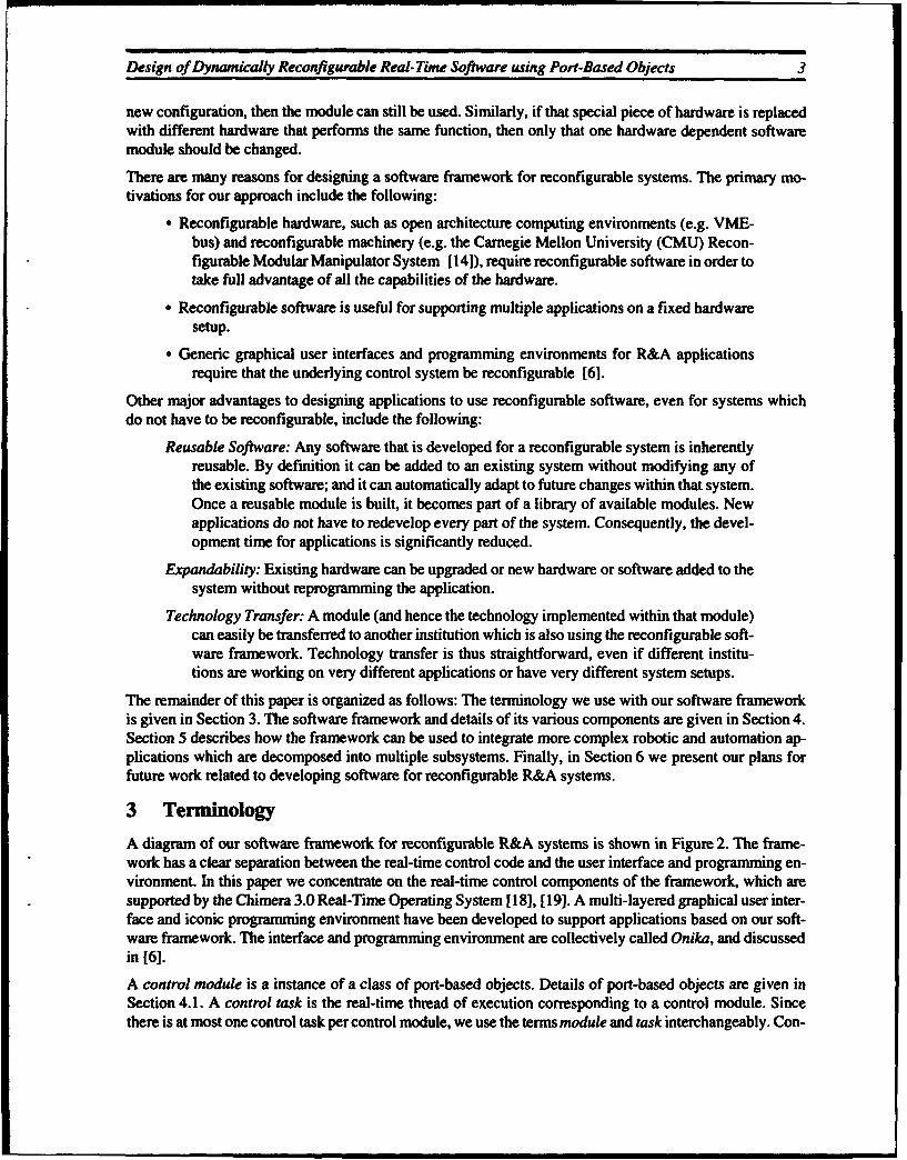
Design of Dynamically Reconfigurable Real-Time Software using Port-Based Objects 3
new configuration, then the module can still be used. Similarly, if that special piece of hardware is replacedwith different hardware that performs the same function, then only that one hardware dependent softwaremodule should be changed.
There are many reasons for designing a software framework for reconfigurable systems. The primary mo-tivations for our approach include the following:
* Reconfigurable hardware, such as open architecture computing environments (e.g. VME-bus) and reconfigurable machinery (e.g. the Carnegie Mellon University (CMU) Recon-figurable Modular Manipulator System [141), require reconfigurable software in order totake full advantage of all the capabilities of the hardware.
* Reconfigurable software is useful for supporting multiple applications on a fixed hardwaresetup.
• Generic graphical user interfaces and programming environments for R&A applicationsrequire that the underlying control system be reconfigurable [6].
Other major advantages to designing applications to use reconfigurable software, even for systems whichdo not have to be reconfigurable, include the following:
Reusable Software: Any software that is developed for a reconfigurable system is inherentlyreusable. By definition it can be added to an existing system without modifying any ofthe existing software; and it can automatically adapt to future changes within that system.Once a reusable module is built, it becomes part of a library of available modules. Newapplications do not have to redevelop every part of the system. Consequently, the devel-opment time for applications is significantly reduced.
Expandability: Existing hardware can be upgraded or new hardware or software added to thesystem without reprogramming the application.
Technology Transfer: A module (and hence the technology implemented within that module)can easily be transferred to another institution which is also using the reconfigurable soft-ware framework. Technology transfer is thus straightforward, even if different institu-tions are working on very different applications or have very different system setups.
The remainder of this paper is organized as follows: The terminology we use with our software frameworkis given in Section 3. The software framework and details of its various components are given in Section 4.Section 5 describes how the framework can be used to integrate more complex robotic and automation ap-plications which are decomposed into multiple subsystems. Finally, in Section 6 we present our plans forfuture work related to developing software for reconfigurable R&A systems.
3 Terminology
A diagram of our software framework for reconfigurable R&A systems is shown in Figure 2. The frame-work has a clear separation between the real-time control code and the user interface and programming en-vironment. In this paper we concentrate on the real-time control components of the framework, which aresupported by the Chimera 3.0 Real-Time Operating System [ 18], [19]. A multi-layered graphical user inter-face and iconic programming environment have been developed to support applications based on our soft-ware framework. The interface and programming environment are collectively called Onika, and discussedin [6].
A control module is a instance of a class of port-based objects. Details of port-based objects are given inSection 4.1. A control task is the real-time thread of execution corresponding to a control module. Sincethere is at most one control task per control module, we use the terms module and task interchangeably. Con-

4 Tech Report CMU-PJ-TR-93-))
user
radgan raphialai Oniwdaiconi
usritrfaver proge~ Chmramm3.0
from snsor Y tolactatore
jcobnicb programsmjb)eeir vr betgrahialintrfce L prtbaysted objectsito
Co subrtoutne caR
F~ue :Sotar raeor orrcofgualesstm
Design of Dynamically Reconfigurable Real-Time Software using Port-Based Objects 5
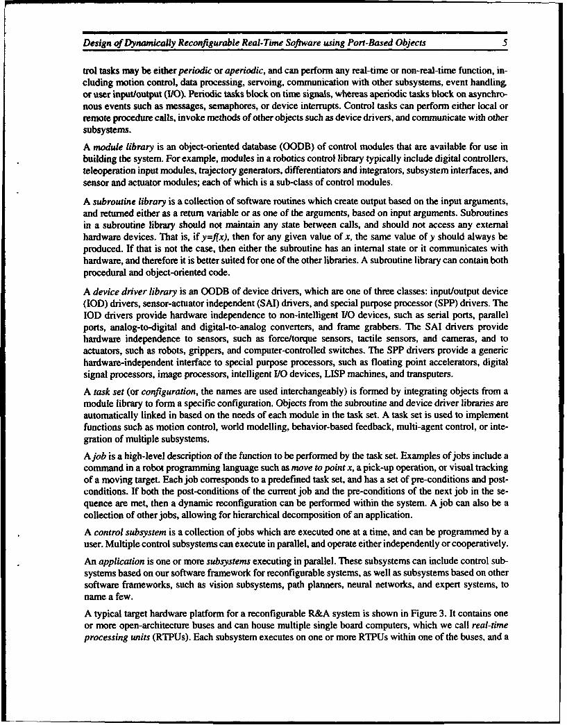
trol tasks may be either periodic or aperiodic, and can perform any real-time or non-real-time function, in-cluding motion control, data processing, servoing, communication with other subsystems, event handling,or user input/output (1/0). Periodic tasks block on time signals, whereas aperiodic tasks block on asynchro-nous events such as messages, semaphores, or device interrupts. Control tasks can perform either local orremote procedure calls, invoke methods of other objects such as device drivers, and communicate with othersubsystems.
A module library is an object-oriented database (OODB) of control modules that are available for use inbuilding the system. For example, modules in a robotics control library typically include digital controllers,teleoperation input modules, trajectory generators, differentiators and integrators, subsystem interfaces, andsensor and actuator modules; each of which is a sub-class of control modules.
A subroutine library is a collection of software routines which create output based on the input arguments,and returned either as a return variable or as one of the arguments, based on input arguments. Subroutinesin a subroutine library should not maintain any state between calls, and should not access any externalhardware devices. That is, if y=flx), then for any given value of x, the same value of y should always beproduced. If that is not the case, then either the subroutine has an internal state or it communicates withhardware, and therefore it is better suited for one of the other libraries. A subroutine library can contain bothprocedural and object-oriented code.
A device driver library is an OODB of device drivers, which are one of three classes: input/output device(IOD) drivers, sensor-actuator independent (SAI) drivers, and special purpose processor (SPP) drivers. TheIOD drivers provide hardware independence to non-intelligent I/O devices, such as serial ports, parallelports, analog-to-digital and digital-to-analog converters, and frame grabbers. The SAI drivers providehardware independence to sensors, such as force/torque sensors, tactile sensors, and cameras, and toactuators, such as robots, grippers, and computer-controlled switches. The SPP drivers provide a generichardware-independent interface to special purpose processors, such as floating point accelerators, digitalsignal processors, image processors, intelligent I/O devices, LISP machines, and transputers.
A task set (or configuration, the names are used interchangeably) is formed by integrating objects from amodule library to form a specific configuration. Objects from the subroutine and device driver libraries areautomatically linked in based on the needs of each module in the task set. A task set is used to implementfunctions such as motion control, world modelling, behavior-based feedback, multi-agent control, or inte-gration of multiple subsystems.
A job is a high-level description of the function to be performed by the task set. Examples of jobs include acommand in a robot programming language such as move to point x, a pick-up operation, or visual trackingof a moving target. Each job corresponds to a predefined task set, and has a set of pre-conditions and post-conditions. If both the post-conditions of the current job and the pre-conditions of the next job in the se-quence are met, then a dynamic reconfiguration can be performed within the system. A job can also be acollection of other jobs, allowing for hierarchical decomposition of an application.
A control subsystem is a collection of jobs which are executed one at a time, and can be programmed by auser. Multiple control subsystems can execute in parallel, and operate either independently or cooperatively.
An application is one or more subsystems executing in parallel. These subsystems can include control sub-systems based on our software framework for reconfigurable systems, as well as subsystems based on othersoftware frameworks, such as vision subsystems, path planners, neural networks, and expert systems, toname a few.
A typical target hardware platform for a reconfigurable R&A system is shown in Figure 3. It contains oneor more open-architecture buses and can house multiple single board computers, which we call real-timeprocessing units (RTPUs). Each subsystem executes on one or more RTPUs within one of the buses, and a

6 Tech Report CMU-RI-TR-93-11
control task executes on one of the RTPUs. Special purpose processors, I/O devices, a host workstation, andother hardware communication links may also be part of the target hardware platform.
4 Description of a Software Framework for Reconfigurable Systems
In this section, the details of our software framework for reconfigurable systems are presented. We start byproviding a description of a port-based object. We then present the state variable table mechanism we havedeveloped for integrating control tasks while maintaining the real-time constraints of a task set. We then
Ethernet
PlanningLevels
host graphics andmainframe workstation workstation file server User Interface
L Host VME bus
Software Development and Simulation (non-real-time)
Real-Time Execution G
Primary VME bus
LevelsReal-Time Real-Time Special Real-Time (May consist of
Processing Processing High-Speed Processing more than oneUnit #1 Unit #2 Processor Unit #3 VME bus)
Alternate High Speed Local Bus
Communication Link(e.g. Fiber Optics) Gateway
Secondary VME busT
I Servo LevelsReal-Time Serial and Real-Time (may consist of
Procssin ] Vision more than oneProcessing Parallel Processing
FiUrity#g System VME bus)Uni #4SseI/0 ports Unit #1
Figure 3: Typical target hardware for a reconflgurable sensor-based control system.

Design of Dynamically Reconfigurable Real-Time Software using Port-Based Objects 7
describe the internal structure of a control module and how it makes use of the state variable table. We giveexamples of a library of software modules, sample configurations, and an example of reconfiguring a taskset. We describe how modules can be combined in order to reduce complexity, save execution time, andreduce bus bandwidth for a configuration. Finally, we describe the hardware independent interfaces of thedevice drivers which are required to develop modules independent of the target hardware setup.
4.1 Port-Based Objects
A port-based object, also called a control module, combines the notions of object-oriented and port autom-aton design paradigms, in that it is defined as an object, but it has various ports for real-time communication.As with any standard object [3], each module has a state and is characterized by its methods. The internalsof the object are hidden from other objects. Only the ports of an object are visible to other objects. A sim-plified model of a port-based object is shown in Figure 4; a more detailed model is given in Section 4.3.Each module has zero or more input ports, zero or more output ports, and may have any number of resourceports. Input and output ports are used for communication between tasks in the same subsystem, while re-source ports are used for communication external to the subsystem, such as with the physical environment,other subsystems, or a user interface.
A link between two objects is created by connecting an output port of one module to a corresponding inputport of another module. A configuration can be legal only if every input port in the system is connected toone, and only one, output port. A single output may be used as input by multiple tasks. In our diagrams, werepresent such fanning of the output with just a dot at the intersection between two links, as shown inFigure 5. In this example, both modules A and B require the same input p, and therefore the module C fansthe single output p into two identical outputs, one for each A and B.
If two modules have the same output ports, then a join connector is required, as shown in Figure 6. A joinconnector is a special object which takes two or more conflicting inputs, and produces a single non-conflict-ing output based on some kind of combining operation, such as a weighted average. In this example modulesA and B are both generating a common, hence conflicting output p. In order for any other module to use p
ip module Ym
resource ports, forcommunication with sensors,
actuators, and other subsystems
Figure 4: Simple model of a port-based object, also called a control module
Figure 5: Fanning an output Into multiple inputs

8 Tech Report CMU-RI-TR-93-11
as an input, it must only connect to a single output p. The modules with conflicting outputs have their outputport variables modified, such that they are two separate, intermediate variables. In our example, the outputof module A becomes p', and the output of module B becomes p ". The join connector takes p' and p" asinputs, and produces a single unambiguous output p.
A task is not required to have both input and output ports. Some tasks instead receive input from or sendoutput to the external environment or to other subsystems, through the resource ports. Other tasks may gen-erate data internally (e.g. trajectory generator) and hence not have any input ports, or just gather data (e.g.data logger), and hence have no output ports.
A sample library of control modules is shown in Figure 7. The following variable notation is used in ourdiagram:
0: joint position x: Cartesian position0: joint velocity x: Cartesian velocity0: joint acceleration i: Cartesian acceleration,r: joint torque f: Cartesian force/torqueJ: Jacobian z: wild-card: match any variable
The following subscript notation is used in our diagram:
d: desired (the final goal)r: reference (the goal for each cycle)m: measured (obtained from sensors on each cycle)u: control signal (a computed control value after each cycle)y: wild-card: match any subscript
The target users of this software framework are control systems engineers, and not software engineers orcomputer scientists. One of our major design decisions was therefore to integrate tasks based on a controlsystems model, where a task set resembles a control systems block diagram, and each input and output portis a state variable, and not a message port. Tasks execute asynchronously, and on each cycle, the most recentdata corresponding to the input port variables is obtained, and at the end of the cycle, the new data corre-sponding to the output port variables is used to update the subsystem's state information.
4.2 Control Module Integration
A task set is formed by selecting objects from the control module library which link together to form eitheran open-loop or closed-loop system. Each object will execute as a separate task on one of the RTPUs in thereal-time environment. An example of a fairly simple task set is the PID joint control of a robot, as shownin Figure 8. It uses three modules taken from the control module library: the joint position trajectory gen-erator, the PID joint position controller, and the torque-mode robot interface.
"P, connector p
Figure 6: Joining multiple outputs into a single input

Design of Dynamically Reconfigurable Real-Time Software using Port-Based Objects 9
As mentioned in the previous section, a legal configuration exists when there is exactly one output port forevery input port in the task set. Such an abstraction is only useful if there exists a straightforward implemen-tation. We now change our focus from software abstractions to the design and implementation of a real-timesystem based on those abstractions.
To support our abstraction of port-based objects, we have designed a state variable table mechanism for pro-viding the real-time intertask communication of a task set in a multiprocessor environment. Our mechanismassumes that each control task is self-contained on a single processor, and that a control subsystem is con-tained within a single open-architecture backplane.
The communication mechanism is based on using global shared memory for the exchange of data betweenmodules, as shown in Figure 9, thus providing communication with minimal overhead. Every input port andoutput port is a state variable. A global state variable table is stored in the shared memory. The variables in
ROWo Interface Modules; Digita Controleirs Teleoperm~on MWpu Modules
_torque-mode ~ o J -Cartesian -\" forw rd - 6-DOF 6-DOF -)
hornro robotrot er Irjeofi. y kidnematics Oy eoctbnteffacej em Xd4i =atr~ i+r and Jacobian~ ~ ~ f
@' from trackbell: from tracitei:
frr obtt rbttraecow -. '- %denc raw reference data raw reference dataraw joint raw torque % 4 In.t_.j kr
position data command Te
1Wrton-mode em * j~oint * dnmc trajectory trjcot.r robot I dmi 4 I igenerator x(d generatorInerac OM~~ Cartesian joint-position 08fro rovote too J multiln
from robottorobot xm from user, file, from user, file.rawjoint joint move xd or path-planning or path-planning
posfel data commnd Ines sui~T bsysteml subystemJr8.- , acelraton~-+'.acceleration X
Dffrentlators and integrators xm corler) mapping .Module
time * M 6-DOF Visuelz . erentlato V x damped f forceltorque I, servoing F
, tm 01 sensor interface
inegatr l from RA sensorraw strain from vision
Sgauge data subsystem
Figure 7: Sample control module library
generator position / ~ , robot I--'!joint position • cotolr, iefae3 m
O d cotolritraeefrom robot: to robot:
from user raw joint joint movepos/vel data command
Figure 8: Example of PID joint control.

10 Tech Report CMU-RI-TR-93-11
this table are a union of the input port and output port variables of all the modules that may be configuredinto the system. Tasks corresponding to each control module cannot access this table directly. Rather, everytask has its own local copy of the table, called the local state variable table.
Only the variables used by the task are kept up-to-date in the local table. Since each task has its own copyof the local table, mutually exclusive access is not required. At the beginning of every cycle of a task, thevariables which are input ports are transferred into the local table from the global table. At the end of thetask's cycle, variables which are output ports are copied from the local table into the global table. This de-sign ensures that data is always transferred as a complete set, since the global table is locked whenever datais transferred between global and local tables.
Each task executes asynchronously. That is, it executes according to its own internal timer, and not accord-ing to a signal received from a different task. This method allows tasks to execute at different rates, and min-imizes the inter-dependency of tasks, thus simplifying the real-time analysis of a configuration. A real-timescheduling algorithm for dynamically reconfigurable systems, such as the maximum-urgency-first algo-rithm [20] can be used to guarantee the time and resource constraints of the task set, assuming that the statevariable table mechanism used for communication is predictable. We now show that our mechanism is pre-dictable when a proper locking mechanism for the global state variable table is selected.
First, we consider the utilization of the open-architecture bus, which is a shared resource among tasks whichexecute on different processors. When using the global state variable table for inter-module communication,the number of transfers per second (Zj) for module Mj can be calculated as follows:
S (xj) + S (yj) + 2A)
Zj = ( (1Tj (i)
where ni is the number of input ports for Mj, mj is the number of output ports for My, x~i is input variable xifor Mi, Yij is output variable yi for Mi, S(x) is the transfer size of variable x, Tj is the period of Mj, and A isthe transfer overhead required for locking and releasing the state variable table for each set of transfers.
Global State Variable Table
local state Iocal state local state local statevariable table variable table variable table variable table
task mule task module task module task moduleAj K, K1
Processor A Processor K
Figure 9: Structure of state variable table mechanism for control module integration

Design of Dynamically Reconfigurable Real-Time Software using Port-Based Objects 11
We assume that there is a single lock for the entire global state variable. The table is locked by a task at mosttwice per cycle: first to transfer all input variables before each cycle, and again to transfer all the output vari-ables at the end of each cycle. If each variable has its own lock, the locking overhead increases to (m+n)A.Advantages of using a single lock for the entire table over using multiple locks, a performance comparison,and details on guaranteeing a bounded waiting time for the task are given in [211.
Whether multiple modules run on the same RTPU, or each module runs on a separate RTPU, the maximumbus bandwidth B required for a particular configuration remains constant. Therefore B can be used to deter-mine whether there is sufficient bus bandwidth for a given configuration. The maximum bus utilization Bfor k modules in a particular configuration, in transfers per second, is
k
B -- Z (2)
j= I
where Zj is the number of transfers per second for module Mi, as computed in (1).
The global state variable table mechanism described in this section has been incorporated into the Chimera3.0 Real-Time Operating System. More details on the implementation can be obtained in the Chimera pro-gram documentation [191.
4.3 Generic Framework of a Port-Based Object
In the previous section we described how control tasks communicate with each other through a state variabletable. We have yet to address the issue of when such communication is to occur. We now refine our softwareabstraction of a port-based object by describing its components, the actions taken by the object in responseto external signals, and the communication performed by the object before and after each of those actions.
A port-based object can have two kinds of input: constant input that needs to be read in only once during itsinitialization (in-const), and variable input which must be read in at the beginning of each cycle (in-var) forperiodic tasks, and at the start of processing an event for aperiodic tasks. Similarly, a task can have outputconstants (out-const) or output variables (out-var). Bt'h the constants and variables are transferred throughthe global state variable table.
The input and output connections shown in the control module library in Figure 7 are all variables; constantinputs and outputs were omitted for the sake of simplicity in presenting the software framework. InFigure 10 we show a sample Cartesian teleoperation configuration which does include both the constantsand variables. The constant connections are shown with a dotted line, while the variable connections areshown with solid lines. The Cartesian controller can be designed for any robotic system if it uses generalizedforward and inverse kinematics [8]. In such a case, the forward kinematics and Jacobian and inverse dy-namics modules require the Denavit-Hartenberg parameters (DH) [5] as input during initialization. In ad-dition, many modules require the number of degrees-of-freedom (NDOF) of the robot. The robot interfacemodule can be designed so that it is dependent on the robotic hardware, but provides a hardware independentinterface to the rest of the system. It generates the constants NDOF and DH, therefore these constants areout-consts. Other modules can then have these constants as input during initialization, and configure them-selves for the robot being used. If the robot is changed, then only the robot interface module needs to bechanged. For fixed-configuration robots, the values of NDOF and DH are typically hard-coded within themodule or stored in a configuration file, while for reconfigurable robots [14], these values are read in fromEPROMs on the robot during initialization of the robot interface module.
The use of in-consts and out-consts by the modules create a necessary order for initialization of tasks withinthe configuration. Tasks that generate out-consts must be initialized before any other task that uses that con-stant as an in-const is initialized.

12 Tech Report CMU-RI-TR-93-11
The code for a control module is decomposed into several components, which are implemented as methodsof the control object, or as subroutines if the control object is defined as an abstract data type. The compo-nents are init, on, cycle, off, kill, error, and clear. The init and on components are for a two-step initializa-tion. The cycle component executes once for each cycle of a periodic task, or once for each event to beprocessed by an aperiodic server. The off and kill components are for a two-step termination. The error andclear components are for automatic and manual recovery from errors respectively. We now go into moredetail on the functionality of each of these components, and the intertask communication which occurs be-fore and after each component is executed. Refer to Figure 11 for a diagram of these components, and howthey relate to the state variable table transfers and events in the system.
A task is created from an object by sending that object a spawn signal. In response to that signal, a newthread of execution is created within the real-time system. The task performs any initialization it requires,including allocating memory, initializing the local state variable table, and initializing resources, by execut-ing its init component. When using an objectvoriented programming language such as C++ for implemen-tation, the init component is the constructor method of the object. Before calling the init component, any in-consts are read from the state variable table, allowing the task to configure itself based on other tasks in thesystem. If the task has any out-consts, these are sent to the state variable table following the execution ofthe init component, allowing for the subsequent initialization of other tasks that require those constants. Af-ter the task is created and initialized, it remains in the OFF state until it receives an on signal.
Once a task is created, it can be turned on (executing) and off (not executing) quickly by sending the taskon and off signals respectively. When the task receives an on signal, both its in-vars and out-vars are trans-ferred from the global state variable table into the local table. The on component is then executed to performa small amount of initialization in order to place the task into a known internal state which is consistent withthe rest of the system. It is generally quite obvious that the in-vars must be read in to update a task's internalstate, but it is not as obvious why the out-vars must also be read in. Control algorithms generally compute
6, r n do dh
o Jacobianam
SI j-1 kinematics -
data an pao sitio dta oman
r 1ndof
zr d acceleration LL accelerationX
Xd - dh_ _.n
takaltime Om inverserqe-od
trackbllct integrator dynamics robotS• xuclt interface
from trackball: from robot: to robot:raw reference r~aw joint raw torque
data psition data command
Figure 10: Example of module integration: Cartesian teleoperation

Design of Dynamically Reconfigurable Real-Time Software using Port-Based Objects 13
NOT
after task receives
'off' states
on cony fromr gWobaluintolocale state varabeatr
reache copyfromloca Intgloba sttevaialetal
ont VIf statSoftas
Pigure 11: returcranewokod ot-ae bet

14 Tech Report CMU-RI-TR-93-11
a new output as a function of its inputs and previous outputs. Normally, the control algorithm remembersits outputs, and therefore only has to read in the inputs from the state variable table. When turning a task on,the control algorithm requires initial values for those output variables to ensure that the system remains sta-ble. These initial values must represent the current state of the system, which is reflected only by the currentvalues in the state variable table. During system start-up initial values are often copied into the state variabletable by the overseeing task, while during a dynamic reconfiguration a different control algorithm that isbeing turned off may have been producing those output variables. Therefore by reading the out-vars beforeexecution of the on component, the control algorithm can properly update its internal view of the system. Ifnecessary, the task can update the out-vars during the on component, and hence the out-vars are copied backto the global state variable table after execution of the on component. The task then enters the ON state.
For as long as the task is in the ON state, the cycle component is executed every time the task receives awakeup signal. For periodic tasks, the wakeup signal comes from the operating system timer, while for ape-riodic tasks, the wakeup signal can result from an incoming message or other asynchronous signallingmechanism supported by the underlying operating system. Before the cycle component is called, in-vars aretransferred from the global state variable table into the local table. After the cycle component finishes, theout-vars are transferred from the local to the global table.
The off component is called in response to a signal which tells the task to stop executing. It is useful fordisabling interrupts and placing final values on the output ports and output resources, to ensure that the sta-bility of the system is maintained while that task is not executing, and to save any internal state or loggeddata onto more permanent storage. The kill component is used to terminate a task and free up any resourcesit had previously allocated. When using an object-oriented programming language, the kill component is theobject's destructor method.
The signals spawn, on, off, and kill are issued externally from the task set, either by the user interface or bythe underlying job control software which perfor ms automatic integration and dynamic reconfiguration oftask sets. The format of these signals is flexible within the framework, and is usually programming environ-ment dependent. In our implementation, these signals can come from a planning task overseeing the appli-cation, a command-line or graphical user interface, or over the network from an external subsystem.
Until now, we have made no mention of errors which may occur during the initialization, execution, or ter-mination of a task. Within our framework, we have adopted the global error handling paradigm, as support-ed by Chimera [181. With global error handling, whenever an error is encountered, an error signal isgenerated. The signal can then be caught by either a user-defined or system-defined error handler.
By default, an error generated during initialization prevents the creation of the task, and immediately callsthe kill component --hi:h can free any resources that had been allocated before the error occurred. If an erroroccurs after a task is initialized, then the error component is called. The purpose of the error component isto either attempt to clear the error, or to perform appropriate alternate handling, such as a graceful degrada-tion or shutdown of the system. It "zý" any reason the task is unable to recover from an error, the task becomessuspended in the ERROR state, and a message sent to the job control task that operator intervention is r -quired. After the problem is fixed, the operator sends a clear signal (from the user interface), at which timethe clear component is called. This code can do any checks to ensure the problem has indeed been fixed. Ifeverything is fine to proceed, then the task returns to the OFF state, and is ready to receive an on signal. Ifthe error has not been corrected, then the task remains in the ERROR state.
A more detailed C-language specification for this control ir rlule interface, which makes use of abstractdata types for implementing objects, is given in [191. Developing a C++ specification for this structure ofa port-object is straightforw;.. ,,-d ' -iart of our future plans. Using an object-oriented programming lan-guage has the advantage of supporting inheritance for separating port-objects into various sub-classes, sim-ilar to the separation shown in Figure 7.

Design of Dynamically Reconfigurable Real-Time Software using Port-Based Objects 15
4.4 Reusing and Reconfiguring Modules
Our software framework is designed especially to support reconfigurable software. In this section, we dem-onstrate that capability by use of an example. Figure 12 and Figure 13 show two different visual servoingconfigurations. Both configurations obtain a new desired Cartesian position from a visual servoingsubsystem [ 13], and supply the robot with new reference joint positions. The configuration in Figure 12 usesstandard inverse kinematics, while the configuration in Figure 13 uses a damped least squares algorithm toprevent the robot from going through a singularity [24]. The visual servoing, forward kinematics and Jaco-bian, and position-mode robot interface modules are the same in both configurations. Only the controllermodule is different.
The change in configurations can occur either statically or dynamically. In the static case, only the objectsrequired for a particular configuration are created. In the dynamic case, the union of all objects required arecreated during initialization of the system. Assuming we are starting up using the configuration in Figure 12,then the inverse kinematics task is turned on immediately after initialization, causing it to run periodically,while the damped least squares and time integrator tasks remain in the OFF state. At the instant that wewant the dynamic change in controllers, we send an off signal to the inverse kinematics task and an on signalto the damped least squares and time integrator tasks. On the next cycle, the new tasks automatically update
xm f voforward ot o t
y kinematics ji J,e daandoJacobiam mm
Figu e a visual sertoin un er dynamic position-mode Omservoing trajectory lxr squares nroboter-a"intefc Xd -•interpolatorj Xr .Jkinematics interface e_ m
from robot: to robot:from vision raw joint joint movesubsystem pos/vel data command
Figure 12: Example of visual servoing using inverse dynamics control module
Xrn forward •Skinematics
-- 'jand Jacobian., Om
integrator
viua J psftinr eviul ateind"" damped • •~iinmd'
servoing -- trajectory x.m robotinterface j •nepltr-br• atqae~ • Interface ;Jem
from robot: to robot:from vision raw joint joint movesubsystem pos/vel data command
Figure 13: Example of visual servoing using damped least squares control module

16 Tech Report CMU-RI-TR-93-11
their own local state variable table, and execute a cycle of their loop, instead of the inverse kinematics taskdoing so. Assuming the on and off operations are fairly low overhead, the dynamic reconfiguration can beperformed without any loss of cycles.
For a dynamic reconfiguration which takes longer than a single cycle, the stability of the system becomes aconcern. In such cases, when the dynamic reconfiguration begins, a global illegal configuration flag is set,which signals to all tasks that a potentially illegal configuration exists. Critical tasks which send signals di-rectly to hardware or external subsystems (e.g. the robot interface module) can go into locally stable execu-tion, in which the module ignores all input variables from other tasks, and instead implements a simplecontrol feedback loop which maintains the integrity of the system. That loop can be something like keepinga robot's position or velocity constant while the dynamic configuration takes place. When the dynamicreconfiguration is complete, the global flag is reset, and the critical tasks resume taking input from the statevariable table.
The illegal configuration flag can also be used when an error is detected in the system. If the execution ofone or more modules is halted because of an error, then the state variable data may no longer be valid. Toprevent damage to the system, critical tasks go into their locally stable execution until the error is cleared orthe system properly shut down. Note that any task with locally stable execution should be considered a crit-ical task for real-time scheduling purposes and thus have highest priority in the system.
4.5 Combining Objects
The model of our port-based objects allows multiple modules to be combined into a single module. This hastwo major benefits: 1) complex modules can be built out of smaller, simpler modules, some or all of whichmay already exist, and hence be reused; and 2) the bus and processor utilization for a particular configura-tion can be improved.
For maximum flexibility, every object is executed as a separate task. This structure allows any object to ex-ecute on any processor, and hence provides the maximum flexibility when assigning tasks to processors.However, the operating system overhead of switching between these tasks can be eliminated if each objectexecutes at the same frequency on the s& me processor. Multiple objects then make up a single larger module,which can then be a single task.
The bus utilization and execution times for updating and reading the global state variable table may also bereduced by combining objects. If data from the interconnecting ports of the objects forming the combinedmodule is not needed by any other module, the global state variable table does not have to be updated. Sincethe objects are combined into a single task, they have a single local state variable table between them. Com-munication between those tasks remains local, and thus reduces the bus bandwidth required by the overallapplication.
The computed torque controller [ I I] shown in Figure 14 is an example of a combined module. It combinesthe PID joint position computation object with the inverse dynamics object. The resulting module has theinputs of the PID joint position computation, and the output of the inverse dynamic object. The intermediatevariable x. does not have to be updated in the global state variable table. In addition, the measured joint po-sition and velocity is only copied from the global state variable once, since by combining the two modules,both modules use the same local table. Combining modules is desirable only if they can execute at the samefrequency on the same RTPU at all times, as a single module cannot be distributed among multiple RTPUs.
4.6 Hardware Independent Interfaces
One of the fundamental concepts of reconfigurable software design is that modules are developed indepen-dent of the target hardware. The issue of hardware independence has been addressed extensively, and is oneof the main goals of any operating system. However, most operating systems do not provide sufficient hard-ware independence that is required by reconfigurable systems.

Design of Dynamically Reconfigurable Real-Time Software using Port-Based Objects 17
UNIX-based real-time operating systems (RTOS) support a device driver concept, where all devices aretreated as files, and the generic C interface routines openo, read(, write(), close(), and ioctl() are used toaccess all functions of the device. This interface works well as long as data transferred between the deviceand program arrives as a steady stream. In sensor-based control systems, however, this is usually not thecase. For example, an analog-to-digital converter (ADC) may have several ports. On each cycle of a periodictask, one or more of the ports must be read. Very often the same device is shared, with different tasks readingfrom different ports. There is no standard method of writing UNIX-like device drivers for these port-based1/0 devices. In many cases, programmers either change the function of the arguments for the read() andwrite() calls, the ioctl() routine is over-used as an interface to every function, or the ports are memorymapped, thus requiring the higher-level software to be responsible for the synchronization and handshakingof the device in a hardware dependent manner.
We now describe the additional hardware independence provided within our framework by using variousclasses of device driver objects. In our abstraction port-based objects communicate with the devices throughresource ports. In our implementation, these resource ports are created by instantiating a device driver ob-ject.
4.6.1 Reconfigurable 1/0 Device Drivers
Reconfigurable software modules must be capable of running on any processor in a multi-processor system.This is often a problem for modules which require access to I/0 devices. Since most UNIX-like RTOS havethe device drivers built into the kernel, each I/0 device in a system is tied to the processor for which its driv-er has been initialized at bootup time. Although this may be acceptable for single-processor systems, it lim-its a software module to a specific RTPU in a multiprocessor system--the one which has the device driverfor the particular device built-in to the kernel-which in turn puts severe constraints on the reconfigurabilityof a task set.
We define the concept of reconfigurable 1/0 device (IOD) drivers for multiprocessor reconfigurable system,in which a device driver can float to any RTPU on the system. Instead of being initialized at bootup time, adevice driver is a standard object (i.e. not a port-based object) is created during the init component of a port-based object, and on the processor on which that task is executing. A global database of device informationis kept on one of the RTPUs, which keeps track of device usage within a subsystem. It is responsible forlocking non-shared devices, and ensuring appropriate cooperation for shared devices.
4d - PID joint ne
"position yinverseOm - controller dynamics
0m0em e
computed torque controller
odid computed
0d torqueFm o m controller
Figure 14: Example of combining modules: a computed torque controller

18 Tech Report CMU-RI-TR-93-11
The IOD driver objects are designed especially for the port-based I/O devices (not to be confused with port-based objects) typical in an R&A system. An 1/0 device is typically a collection of ports. A task opens eitherall or a subset of the ports for the I/O device. If only a subset of ports are used, the remaining ports are avail-able to other tasks. The device can be opened from any RTPU, but once opened, the device remains lockedfor that RTPU until all tasks using it close it. It can then be reopened by a task on any RTPU in the system.Since multiple ports from the same 1/0 port usually share one or more registers, any synchronization re-quired to access different ports from different tasks can be built-in to the IOD drivers, and thus hidden fromany higher level code.
In most operating systems that have drivers built-in to the kernel, a new kernel must be rebuilt every timenew devices are added into the system. This practice is not suitable for reconfigurable systems, as it mustbe possible to add and remove devices, without rebuilding any code. To do so, the objects are stored in anOODB and is loaded at run time, and the device drivers execute in user mode, and not in privilege mode. Inour Chimera implementation which uses abstract data types for implementing objects, the OODB is con-structed as a configuration file; the underlying driver code is data-driven, such that it becomes automaticallyconfigured to use the devices available in the system. Adding, removing, or modifying the characteristicsof a device is then a matter of modifying a configuration file only, with no code recompilation.
4.6.2 Sensor-Actuator Interface and Drivers
Another shortcoming of the UNIX-based device driver methodology is that a hardware independent inter-face is provided to 1/0 devices only, and not to any equipment that may be attached to the device. There areno provisions in traditional real-time operating systems to provide a hardware independent interface to thesensors and actuators connected to the I/O devices. As a result, code must be written with knowledge of the
types of sensors and actuators in the system, hence the software modules are hardware dependent.
To alleviate this problem we have defined a class of sensor-actuator independent (SAI) objects that provide
a hardware independent layer to all sensors and actuators. Sensors and actuators have a set of input and out-put variables, similar to the inputs and outputs of the control modules. Similar sensors would have similarvariables. The sensor-actuator driver contains any hardware specific code for the particular sensor or actu-ator, which may include scaling raw data into typed data, reading a specific type of I/O device, preprocess-ing the data, and controlling the synchronization of the sensor or actuator.
Consider force-torque sensors from two different manufacturers: one requires a parallel I/O port for com-munication, the other requires an analog-to-digital converter. Because of the different 1/0 interfaces, eachone must perform different kinds of device initialization. The raw data from each may also be different, andmust be scaled according to the calibration matrices of the particular sensor. In any case, the output fromboth sensors is identical-3 force readings and 3 torque readings. Thus both of these sensors would providethe same output variable of measured force/torque. As with the control modules, SI units are used for allvariables. A module that requires force data can read the measured force variable through any SAI objectthat produces force/torque data. The module is compatible with any force-torque sensor, and hence the re-
quired hardware independence for the module has been achieved, allowing it to be used in a reconfigurablesystem.
More details of a C-language specification using abstract data types for an SAI interface has been definedin Chimera and is given in [19]. SAI objects have already been written for several sensors and actuators,including the Puma robot, Direct Drive Arm II Robot [71, [23], CMU Reconfigurable Modular ManipulatorSystem [14], both Lord and Assurance Technology force/torque sensors, Dimension-6 trackball, and an Im-
aging Technology vision subsystem.

Design of Dynamically Reconfigurable Real-Time Software using Port-Based Objects 19
4.6.3 Special Purpose Processor Interface and Drivers
Most operating systems attempt to treat all hardware, including special purpose processors (SPPs) such asfloating point accelerators, image processors, LISP machines, transputers, and digital signal processors, asfiles. The basic function of an SPP is so different from any file or 1/0 device that the traditional reado,write(), and ioctl() do not provide an adequate interface. These operating systems generally provide someform of memory mapping function (e.g. mmapO) which allows mapping the entire memory and registers ofthe SPP into user space. Commercial manufacturers of the SPPs write their own custom interface to the SPPto bypass the standard device driver interface, and provide commands such as download, call, and transfer-data. As a result, every SPP has its own unique interface, and hence the code using the interface is hardwaredependent.
We define a class of special purpose processor objects, which provide a hardware independent interface toSPPs. The SPP objects have characteristics similar to the reconfigurable 1/0 device drivers, in that it oper-ates at the lowest level and communicates directly with the hardware. It has generic driver components forinitializing and downloading code to the SPP, translating subroutine names into local pointers, makingtransparent remote procedure calls, transferring data between the SPP and RTPU, and synchronizing atask's execution with the SPP's execution. Remote procedure calls from a control task to an SPP are thushandled internally by the object, and hence transparent to the remainder of the application.
The C-language specification using abstract data types for the SPP objects has been defined in [ 19i and issupported by Chimera. SPP drivers have already been implemented for the Mercury 3200 and SKYbolt i860Floating Point Accelerators.
5 Systems Integration
In simpler applications, a few control modules is sufficient to implement a feedback loop to control a robot.In more complex systems, however, there may be many subsystems, including multiple control feedbackloops to control multiple robots or complex grippers, and external subsystems such as path planners, visionsystems, and expert systems. When the application consists of multiple subsystems, a higher-level softwarearchitecture is used to describe the interconnections between subsystems.
Our software framework is designed to be independent of the software architecture used for an application.An application is designed as one or more subsystems. The subsystems can either be control feedback loops,which make use of reconfigurable software modules as described previously in this paper, or consist of asingle module, which is an interfacing module to an external subsystem.
There is generally two types of conmnunication between subsystems: aperiodic or periodic. Aperiodic com-munication occurs on an as-needed basis, while periodic communication occurs at regular intervals. Withinour framework, there are no constraints as to what kind of communication can be used between subsystems,as long as the interfacing module within each subsystem uses the same mechanism. In this section, wepresent some of the mechanisms available in Chimera 3.0.5.1 Aperiodic Communication
When tasks communicate aperiodically, usually a message is sent, which contains either a command or newdata, or a signal is sent to the other subsystem. In Chimera 3.0, the multiprocessor priority message passingcan be used to send messages between subsystems, and the remote semaphores can be used to send signalsto a remote subsystem [ 181. Other user-defined mechanisms can also be used if necessary.
A subsystem interfacing module is an aperiodic server, which waits for a message or signal from the remotesubsystem. When the signal is received, the aperiodic server executes its cycle component, which can eitherparse the data in the message, or read from a shared memory location which now contains the data. After

20 Tech Report CMU-RI-TR-93-11
filtering or processing the data (if necessary) the data is placed on its output ports, which in turn updates thatsubsystem's global state variable table.
5.2 Periodic Communication
When multiple subsystems must communicate with each other periodically, there are several real-time con-cerns that come into play, including the following:
"• Communication should be non-blocking, so that the real-time considerations of eachsubsystem can be isolated from other subsystems.
"* Interfacing modules in each subsystem may not be executing at the same rate; whenever thereceiving module requires new information, the most recent data must be obtained.
"* The two subsystems may be on different buses; although some shared memory is available,hardware synchronization such as semaphores or the test-and-set instruction is notavailable.
We have designed and implemented a communication mechanism which addresses these issues. It providesnon-blocking periodic real-time communication with other subsystems. Like the state variable table mech-anism, it relies on state information, where the most recent data is always read by the receiving module.
Between subsystems, we assume that there is a one-to-one communication link and a fixed amount of datato be transferred on each cycle. One task is the sender, and writes data into shared memory periodically,while the other task is the receiver, and reads from that shared memory periodically. Such communicationhas sometimes been implemented using a double-buffer technique. While the sender is writing the data intoone buffer, the receiver can read the data from the other buffer. When both are finished, they swap bufferpointers, and can continue with the next buffer. This method insures that the sender and receiver are neveraccessing the same data at the same time. There are major problems with this scheme, however. It requiresthat both tasks operate at the same frequency and be properly synchronized. Alternately, the tasks may beat different frequencies, but if those frequencies are not multiples of each other, then one task ends up con-stantly blocking while the other task tries to finish using the buffer. Another problem exists if there is a clockskew between the clocks of the two tasks, which can also cause undesirable blocking between the tasks.
A solution to this problem is to use three buffers instead of two. At any given time, there is always one buffernot in use. When one of the two tasks finishes with its buffer, it can immediately use the free buffer. Thisallows both tasks to execute independently and not block. Flowcharts of the algorithms used for the senderand receiver are shown in Figure 15. The receiver always reads the most recent data, and neither the receivernor sender ever block because a buffer is not ready.
A time-stamp is attached to each data item, which keeps track of when the data was generated. The time-stamp may be either the physical time when the data was generated, or a counter that is incremented oncefor each data item generated. In the Chimera 3.0 implementation, both are provided. The physical time isuseful if a task must differentiate or integrate the data over time. The counter makes it easier to check howmany data packets were lost if the receiver is slower than the sender. If the time-stamp of the current dataread by the receiver is the same as the time-stamp of the previous data read, then the receiver is executingfaster than the sender, and hence it must reuse the old data.
Since there is usually no test-and-set or equivalent hardware synchronization available between the sub-systems, the triple buffering mechanism uses a software mutual exclusion algorithm [161 to ensure the in-tegrity of all buffers in the case where both the sender and receiver are trying to switch bufferssimultaneously. The algorithm uses polling if the lock is not obtained on the first try. However, since thelock is only kept for as long as it takes to switch the buffer pointer (less than 5 iisec on an MC68030), settinga polling time equal to 5 ipsec on an MC68030 ensures that the task never has to retry more than once, andits maximum waiting time for the lock is less than two times the polling time. For real-time analysis, this

Design of Dynamically Reronfigurable Real- Time Software using Port-Based Objects 21
time can be considered execution time, and not blocking time. In the Chimera implementation, the synchro-nization is completely transparent to the user.
6 Future Work
The software framework we describe has proven to be an extremely valuable tool for building R&A appli-cations. The methodology is being used at Carnegie Mellon University with the Direct DriveArm 1I [7], [23], the Reconfigurable Modular Manipulator System [141, the Troikabot System for RapidAssembly [9], and the Self-Mobile Space-Manipulator [41, and at the Jet Propulsion Laboratory, CaliforniaInstitute of Technology, on a Robotics Research 7-DOF redundant manipulator [221. These systems allshare the same software framework. In many cases, the systems also share the same software modules. Thesensors, actuators, and computing hardware used for any particular experiment on any of these systems canbe reconfigured in a matter of seconds, and the software can be reconfigured dynamically. By using theframework, we can install new systems and get applications up and running in a matter of days, instead ofthe several months it took us before we began to use our framework.
Despite our current success, there are still many issues that have not yet been resolved. Some of the issuesinclude the following:
"* The global allocation of tasks to RTPUs is currently done manually. A global schedulingalgorithm which can automatically map these tasks to the RTPUs based on the timing andresource constraints of each task within a subsystem is required.
"* The real-time analysis of a configuration requires that the CPU time required by a modulebe known a priori. This is often difficult to obtain, especially in a multiprocessorapplication where the RTPUs are not necessarily the same type, and thus the task may
sender receiver
wait for start of wait for start ofcycle sign&; cycle signal
acquire an acquire oldest acquire newest reuse buffer fromlEMPTY buffer unused buffer FULL buffer previous cycle
with new data of buffer
as FULL E# EPTY
lFigure 15: Flowchart of the sender and reciver tasks for trple-buffered communication

22 Tech Report CMU-RI-TR-93-11
have different CPU requirements for each RTPU. We are looking into automaticallyprofiling the tasks in order to obtain fairly accurate first estimates of execution time, andto be able to automatically adjust the estimates during run-time if the original estimatesare incorrect.
" Most real-time scheduling concentrates on guaranteeing that critical tasks meet theirdeadlines in a hard real-time system. However, many R&A applications have at most oneor two hard real-time tasks, and the remaining tasks are soft real-time. We are currentlyanalyzing the potential for using soft real-time scheduling algorithms in order to improvethe functionality of an R&A application without adding additional hardware, and henceadditional costs to the system.
"• Currently the dynamic reconfiguration is performed under program control or by the user.The underlying operating system does not ensure that the stability of a system ismaintained. We are further studying the possibility of having the critical tasks in thesystem remain locally stable during dynamic reconfiguration. This means that the taskignores its input ports whenever an invalid configuration is detected, and instead ensureslocally that the hardware it is controlling remains stable. These same mechanisms can beused if errors in the system are detected, and the system must either remain stable orperform a graceful degradation or shutdown.
"• We have implemented all our objects in Chimera using abstract data types in C, andsubroutine calls for each of an objects components. A logical next step is to use an object-oriented programming language, such as C++, which would give us the advantage ofobject inheritance for further improving the reusability of existing application code.
Along with the foundation provided by the software framework, we are also developing many modules forthe control module, device driver, and subroutine libraries. As the libraries continue to grow, they will formthe basis of code that can eventually be used by future R&A applications. There will no longer be a need fordeveloping software from scratch for new applications, since many required modules will already be avail-able in one of the libraries.
7 Acknowledgments
The research reported in this paper is supported, in part by, U.S. Army AMCOM and DARPA under con-tract DAAA-2189-C-0001, the National Aeronautics and Space Administration (NASA) under contractNAGl-1075, the Department of Electrical and Computer Engineering, and by The Robotics Institute at Car-negie Mellon University. Partial support for David B. Stewart is provided by the Natural Sciences and En-gineering Research Council of Canada (NSERC) through a Graduate Scholarship.
Part of the research reported in this paper was also performed for the Jet Propulsion Laboratory (JPL), Cal-ifornia Institute of Technology, for the Remote Surface Inspection system development and accomparyingprojects [22] under a contract with NASA. Reference herein to any specific commercial product, process,or service by trade name, trademark, manufacturer, or otherwise, does not constitute or imply its endorse-ment by the United States Government or JPL.
We would like to thank Professor Mary Shaw (School of Computer Science, Carnegie Mellon University)for giving us the opportunity of presenting this work to her software architecture reading group from whichwe obtained valuable feedback, and for her many comments which have helped us improve the presentationof our work.

Design of Dynamically Reconfigurable Real-Time Software using Port-Based Objects 23
8 References
[11 J. M. Adan, M. F. Magalhaes, "Developing reconfigurable distributed hard real-time control systemsin STER," in Algorithms and Architectures for Real-Time Control, Proc. of the IFAC Workshop(Oxford, U.K.: Pergamon), pp. 147-52, September 1991.
[2] T. E. Bihari, P. Gopinath, "Object-oriented real-time systems: concepts and examples," Computer,
vol. 25, no. 12, pp. 25-32, December 1992.
13] G. Booch, "Object-oriented development," IEEE Transactions on Software Engineering, vol. SE-12,no. 2, pp. 211-221, February 1986.
[4] H. B. Brown, M. B. Friedman, T. Kanade, "Development of a 5-DOF walking robot for space stationapplication: overview," in Proc. of 1990 IEEE International Conference on Systems Engineering,Pittsburgh, Pennsylvania, pp. 194-197, August 1990.
[5] J. J. Craig, Introduction to Robotics, 2nd Ed., (Reading, Massachusetts: Addison Wesley PublishingCompany), 1989.
[6] M. W. Gertz, D. B. Stewart, and P. K. Khosla, "A Software architecture-based human-machine inter-face for reconfigurable sensor-based control systems," in Proc. of 8th IEEE International Sympo-sium on Intelligent Control, Chicago, Illinois, August 1993.
[7] T. Kanade, P.K Khosla, and N. Tanaka, "Real-time control of the CMU Direct Drive Arm II usingcustomized inverse dynamics," in Proc. of the 23rd IEEE Conference on Decision and Control, LasVegas, NV, pp. 1345-1352, December 1984.
[8] L. Kelmar and P. K. Khosla, "Automatic generation of forward and inverse kinematics for a recon-figurable modular manipulators systems," in Journal of Robotics Systems, vol.7, no.4, pp. 599-619,August 1990.
[9] P. K. Khosla, R. S. Mattikalli, B. Nelson, and Y. Xu, "CMU Rapid Assembly System," in Video Proc.of the 1992 IEEE International Conference on Robotics and Automation, Nice, France, May 1992.
[10] D. M. Lyons and M. A. Arbib, "A formal model of computation for sensory-based robotics," IEEETransactions on Robotics and Automation, vol 5, no. 3, pp. 280-293, June 1989.
[11] B. Markiewicz, "Analysis of the computed-torque drive method and comparison with the conven-tional position servo for a computer-controlled manipulator," Technical Memorandum 33-601, TheJet Propulsion Laboratory, California Institute of Technology, Pasadena, California, March 1973.
[12] D. Miller and R. C. Lennox, "An object-oriented environment for robot system architectures," inProc. of 1990 IEEE International Conference on Robotics and Automation, Cincinnati, Ohio, pp.352-361, May 1990.
[13] N. P. Papanikolopoulos, P. K. Khosla, and T. Kanade, "Vision and control techniques for roboticvisual tracking", in Proc. of 1991 IEEE International Conference on Robotics and Automation, pp.857-864, May 1991.
[14] D. E. Schmitz, P. K. Khosla, and T. Kanade, "The CMU reconfigurable modular manipulatorsystem," in Proc. of the International Symposium and Exposition on Robots (designated 19th ISIR),Sydney, Australia, pp. 473-488, November 1988.
[15] K. Schwan, P. Gopinath, and W. Bo, "Chaos: kernel support for objects in the real-time domain,"IEEE Transactions on Computers, vol. C-36, no. 8, pp. 904-916, August 1987.
[16] A. Silberschatz and J. L. Peterson, Operating System Concepts, Alternate Ed.,(Reading, Mass: Add-ison-Wesley) 1989.

24 Tech Report CMU-RI-TR-93-11
[17] M. Steenstrup, M. A. Arbib, and E. G. Manes, "Port automata and the algebra of concurrent pro-cesses," Journal of Computer and System Sciences, vol. 27, no. 1, pp. 29-50, August 1983.
[181 D. B. Stewart, D. E. Schmitz, and P. K. Khosla, "The Chimera II real-time operating system foradvanced sensor-based robotic applications," IEEE Transactions on Systems, Man, and Cybernet-ics, vol. 22, no. 6, pp. 1282-1295, November/December 1992.
[19] D. B. Stewart and P. K. Khosla, Chimera 3.0 Real-Time Programming Environment, Program Docu-mentation, Dept. of Elec. and Comp. Engineering and The Robotics Institute, Carnegie Mellon Uni-versity, Pittsburgh, PA 15213; to obtain copy electronically, send email to <[email protected]>;July 1993.
[20] D. B. Stewart and P. K. Khosla, "Real-time scheduling of dynamically reconfigurable systems," inProc. of 1991 International Conference on Systems Engineering, Dayton, Ohio, pp. 139-142,August 1991.
[21] D. B. Stewart, R. A. Volpe, and P. K. Khosla, "Integration of real-time software modules for recon-figurable sensor-based control systems," in Proc. 1992 IEEE/RSJ International Conference onIntelligent Robots and Systems (IROS '92), Raleigh, North Carolina, pp. 325-333, July 1992.
[22] S.T. Venkataraman, S. Gulati, J. Barhen, and N. Toomarian, "Experiments in parameter learning andcompliance control using neural networks," in Proceedings of the 1992 American Control Confer-ence, July 1992.
[23] R. A. Volpe, Real and Artificial Forces in the Control of Manipulators: Theory and Experimentation,Ph.D. Thesis, Dept. of Physics, Carnegie Mellon University, Pittsburgh, Pennsylvania, September1990.
[241 C. Wampler and L. Leifer, "Applications of damped least-squares methods to resolved-rate andresolved-acceleration control of manipulators," ASME Journal of Dynamic Systems, Measurement,and Control, vol. 110, pp. 31-38, 1988.