Dsp
22
Ehsan Shams Saeed Sharifi Tehrani
-
Upload
hari-unnikrishnan -
Category
Documents
-
view
217 -
download
0
description
DSP PPT
Transcript of Dsp

Ehsan Shams
Saeed Sharifi Tehrani

What is DSP ?
Digital Signal Processing (DSP) is used in a wide variety of applications, and it is hard to find a good definition that is general.
changing or analyzing information which is measured as discrete sequences of numbers
TMS320C25 DSP

DSP Algorithm
TMS320C25 DSP
Example : Digital Filters (e.g. Digital FIR Filters ,...)
Most share common features:•They use a lot of maths (multiplying and adding signals) •They deal with signals that come from the real world •They require a response in a certain time

Why DSP Processors?
A Comparison :
As shown ,DSP Processors are more efficient
TMS320C25 DSP

TMS320C25 DSP
Why DSP Processors? (Contd.)
As in FIR FiltersAs in FIR Filters

TMS320C25 DSP
Texas Instruments,the company
designer and supplier of digital signal processing and analog technologies
Six decades of history
TI envisions a world where every wireless call, every phone call and every Internet connection is touched by a Digital Signal Processor (DSP).

TMS320C25 DSP
History of the TMS320 family
This family currently includes five generations of DSPs. TMS320C1x,TMS320C2x, TMS320C3x, TMS320C4x, and TMS320C5x
TMS320C1x,TMS320C2x, TMS320C3x, TMS320C4x, and TMS320C5x
TMS320C25, a CMOS 40-MHz digital signal processor capable of twice the performance of the TMS320C1x devices
is capable of executing 10 million instructions per second.
24 additional instructions (133 total)
eight auxiliary registers
an eight-level hardware stack
4K words of on-chip program ROM
low power dissipation inherent to CMOS

TMS320C25 DSP
Architectural overview
Harvard architecture
On-chip memory
ALU
Multiplier
Memory interface
Serial ports
Multiprocessing applications
Direct Memory Access

TMS320C25 DSP
TMS320C25 Functional Block Diagram

Memory Organization
TMS320C25 DSP
Total of 544 16-bit words of on-chip data RAM,
288 words are always data memory and the remaining 256 words maybe configured as either program or data memory.
The TMS320C2x can address a total of 64K words of data memory.
Program and Data MemoryProgram and Data Memory

TMS320C25 DSP
Memory Organization (Cntd.)
Three separate address spaces for program memory, data memory, and I/O
spaces are distinguished externally by means of the PS, DS, and IS
spaces are distinguished externally by means of the PS, DS, and IS
The on-chip program ROM can be mapped into the lower 4K words of program
memory. This ROM is enabled when MP/MC is set to a logic low.
The on-chip program ROM can be mapped into the lower 4K words of program
memory. This ROM is enabled when MP/MC is set to a logic low.

TMS320C25 DSP
Memory Organization (Auxiliary Registers)
register file containing eight auxiliary registers (AR0–AR7).
ARAU is useful for address manipulation
it may also serve as an additional general-purpose arithmetic unit

TMS320C25 DSP
Memory Organization (Memory Addressing Modes)
In the direct addressing mode, the 9-bit data memory page pointer (DP) points to one of 512 pages, each page consisting of 128 words.
In the direct addressing mode, the 9-bit data memory page pointer (DP) points to one of 512 pages, each page consisting of 128 words.
In the indirect addressing mode, the currently selected 16-bit auxiliary register AR(ARP) addresses the data memory through the auxiliary register file bus(AFB).
In the indirect addressing mode, the currently selected 16-bit auxiliary register AR(ARP) addresses the data memory through the auxiliary register file bus(AFB).
When an immediate operand is used, it is contained either within the instruction word itself or in the word following the instruction opcode .
When an immediate operand is used, it is contained either within the instruction word itself or in the word following the instruction opcode .

TMS320C25 DSP
CALU
A typical ALU instruction:1) Data is fetched from the RAM on the data bus,2) Data is passed through the scaling shifter and the ALU3) The result is moved into the accumulator.
Scaling Shifter
ALU and accumulator
Multiplier;T and P registers

TMS320C25 DSP
System Control
16-bit program counter (PC)
hardware stack of eight locations
TMS320C25 DSP
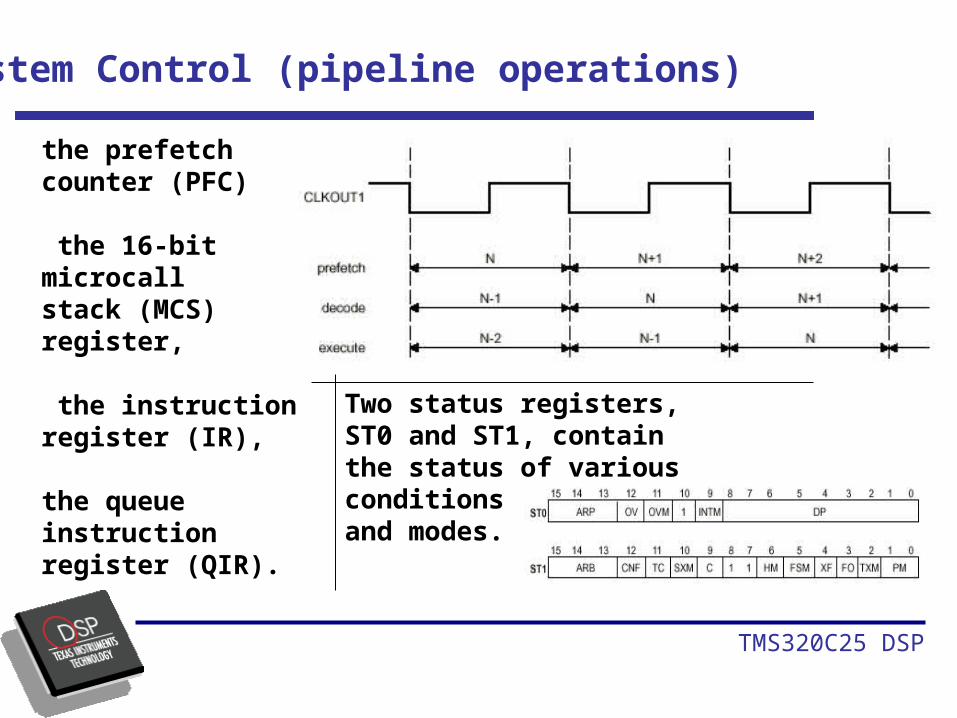
System Control (pipeline operations)
the prefetch counter (PFC)
the 16-bit microcallstack (MCS) register,
the instruction register (IR),
the queue instructionregister (QIR).
Two status registers, ST0 and ST1, contain the status of various conditionsand modes.

TMS320C25 DSP
System Control (Timer Operation+Repeat Counter)
The TMS320C2x provides a memory-mapped 16-bit timer (TIM) register anda 16-bit period (PRD) register.
The on-chip timer isa down counter that is continuously clocked by CLKOUT1.
The repeat counter (RPTC) is an 8-bit counter.It can be loaded with a number from 0 to 255 . RPTC is cleared by reset.

TMS320C25 DSP
External Memory and IO Interface
A 16-bit parallel data bus (D15–D0), A 16-bit address bus (A15–A0), Data, program, and I/O space select (DS, PS, and IS) signals, and Various system control signals.
6) Program Internal ROM/Data External (PR/DE)
1) Program Internal RAM/Data Internal (PI/DI)2) Program Internal RAM/Data External (PI/DE)
3) Program External/Data Internal (PE/DI)
4) Program External/Data External (PE/DE)
5) Program Internal ROM/Data Internal (PR/DI)

TMS320C25 DSP
Interrupts
three external maskable user interrupts (INT2–INT0),
Internal interrupts are generated by the serial port (RINT and XINT), by the timer (TINT), and by the software interrupt (TRAP) instruction.
The TMS320C2x has a built-in mechanism for protecting multicycle instructions
from interrupts.

TMS320C25 DSP
Serial Ports
A full-duplex on-chip serial port provides direct communication with serial devices such as codecs, serial A/D converters, and other serial systems.
If the serial port is not being used, the DXR and DRR registers can be used
as general-purpose registers.
If the serial port is not being used, the DXR and DRR registers can be used
as general-purpose registers.

TMS320C25 DSP
Direct Memory Access
The flexibility of the TMS320C2x allows configurations to satisfy a wide range of system requirements:
A standalone system (single processor),
A multiprocessor with devices in parallel,
A host/slave multiprocessor with shared global data memory space
A peripheral processor
In a multiprocessor environment, the SYNC input can be used to greatly ease interface between processors.
For multiprocessing applications, the TMS320C2xs allocates global data memory space and communicates with that space via the BR (bus request) and READY control signals.