DSP-E800 AV PROCESSOR/AMPLIFIER · yamaha canada music ltd. 135 milner ave., scarborough, ontario...
38
BG DSP-E800 AV PROCESSOR/AMPLIFIER AMPLIFICATEUR D’EFFETS AUDIO-VIDEO OWNER’S MANUAL MODE D’EMPLOI BEDIENUNGSANLEITUNG BRUKSANVISNING MANUALE DI ISTRUZIONI MANUAL DE INSTRUCCIONES GEBRUIKSAANWIJZING
Transcript of DSP-E800 AV PROCESSOR/AMPLIFIER · yamaha canada music ltd. 135 milner ave., scarborough, ontario...

YAMAHA ELECTRONICS CORPORATION, USA 6660 ORANGETHORPE AVE., BUENA PARK, CALIF. 90620, U.S.A.YAMAHA CANADA MUSIC LTD. 135 MILNER AVE., SCARBOROUGH, ONTARIO M1S 3R1, CANADAYAMAHA ELECTRONIK EUROPA G.m.b.H. SIEMENSSTR. 22-34, 25462 RELLINGEN BEI HAMBURG, F.R. OF GERMANYYAMAHA ELECTRONIQUE FRANCE S.A. RUE AMBROISE CROIZAT BP70 CROISSY-BEAUBOURG 77312 MARNE-LA-VALLEE CEDEX02, FRANCEYAMAHA ELECTRONICS (UK) LTD. YAMAHA HOUSE, 200 RICKMANSWORTH ROAD WATFORD, HERTS WD1 7JS, ENGLANDYAMAHA SCANDINAVIA A.B. J A WETTERGRENS GATA 1, BOX 30053, 400 43 VÄSTRA FRÖUNDA, SWEDENYAMAHA MUSIC AUSTRALIA PTY, LTD. 17-33 MARKET ST., SOUTH MELBOURNE, 3205 VIC., AUSTRALIA Printed in Malaysia V584180
BG
DSP-E800AV PROCESSOR/AMPLIFIERAMPLIFICATEUR D’EFFETS AUDIO-VIDEO
OWNER’S MANUALMODE D’EMPLOI
BEDIENUNGSANLEITUNGBRUKSANVISNING
MANUALE DI ISTRUZIONIMANUAL DE INSTRUCCIONES
GEBRUIKSAANWIJZING
DS
P-E
800
CAUTION
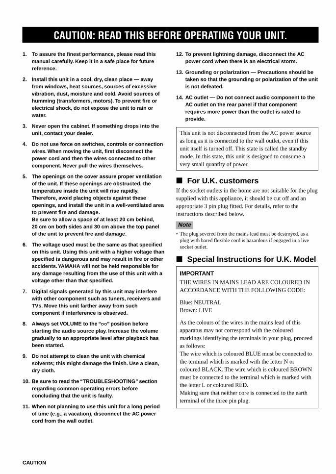
CAUTION: READ THIS BEFORE OPERATING YOUR UNIT.
1. To assure the finest performance, please read thismanual carefully. Keep it in a safe place for futurereference.
2. Install this unit in a cool, dry, clean place — awayfrom windows, heat sources, sources of excessivevibration, dust, moisture and cold. Avoid sources ofhumming (transformers, motors). To prevent fire orelectrical shock, do not expose the unit to rain orwater.
3. Never open the cabinet. If something drops into theunit, contact your dealer.
4. Do not use force on switches, controls or connectionwires. When moving the unit, first disconnect thepower cord and then the wires connected to othercomponent. Never pull the wires themselves.
5. The openings on the cover assure proper ventilationof the unit. If these openings are obstructed, thetemperature inside the unit will rise rapidly.Therefore, avoid placing objects against theseopenings, and install the unit in a well-ventilated areato prevent fire and damage.Be sure to allow a space of at least 20 cm behind,20 cm on both sides and 30 cm above the top panelof the unit to prevent fire and damage.
6. The voltage used must be the same as that specifiedon this unit. Using this unit with a higher voltage thanspecified is dangerous and may result in fire or otheraccidents. YAMAHA will not be held responsible forany damage resulting from the use of this unit with avoltage other than that specified.
7. Digital signals generated by this unit may interferewith other component such as tuners, receivers andTVs. Move this unit farther away from suchcomponent if interference is observed.
8. Always set VOLUME to the “ m” position beforestarting the audio source play. Increase the volumegradually to an appropriate level after playback hasbeen started.
9. Do not attempt to clean the unit with chemicalsolvents; this might damage the finish. Use a clean,dry cloth.
10. Be sure to read the “TROUBLESHOOTING” sectionregarding common operating errors beforeconcluding that the unit is faulty.
11. When not planning to use this unit for a long periodof time (e.g., a vacation), disconnect the AC powercord from the wall outlet.
12. To prevent lightning damage, disconnect the ACpower cord when there is an electrical storm.
13. Grounding or polarization — Precautions should betaken so that the grounding or polarization of the unitis not defeated.
14. AC outlet — Do not connect audio component to theAC outlet on the rear panel if that componentrequires more power than the outlet is rated toprovide.
This unit is not disconnected from the AC power sourceas long as it is connected to the wall outlet, even if thisunit itself is turned off. This state is called the standbymode. In this state, this unit is designed to consume avery small quantity of power.
For U.K. customersIf the socket outlets in the home are not suitable for the plugsupplied with this appliance, it should be cut off and anappropriate 3 pin plug fitted. For details, refer to theinstructions described below.
Note• The plug severed from the mains lead must be destroyed, as a
plug with bared flexible cord is hazardous if engaged in a livesocket outlet.
Special Instructions for U.K. Model
IMPORTANT
THE WIRES IN MAINS LEAD ARE COLOURED INACCORDANCE WITH THE FOLLOWING CODE:
Blue: NEUTRALBrown: LIVE
As the colours of the wires in the mains lead of thisapparatus may not correspond with the colouredmarkings identifying the terminals in your plug, proceedas follows:The wire which is coloured BLUE must be connected tothe terminal which is marked with the letter N orcoloured BLACK. The wire which is coloured BROWNmust be connected to the terminal which is marked withthe letter L or coloured RED.Making sure that neither core is connected to the earthterminal of the three pin plug.
101.E800_Cau(Eng) 5/18/0, 1:36 PM2

English
BA
SIC
OP
ER
ATIO
NADVAN
CED
OPER
AT
ION
AP
PE
ND
IXIN
TR
OD
UC
TIO
NP
RE
PAR
ATIO
N
E-1
INTRODUCTION
Manufactured under license from Digital Theater Systems,Inc. US Pat. No. 5,451,942 and other world-wide patentsissued and pending. “DTS”, “DTS Digital Surround”, aretrademarks of Digital Theater Systems, Inc. Copyright 1996Digital Theater Systems, Inc. All Rights Reserved.
FEATURES
The DSP-E800 makes it possible for you to enjoy advancedsurround sound with a 5.1 channel system by connecting itto your present main amplifier.
Built-in 3-Channel Power Amplification Minimum RMS Output
(0.06% THD, 20 Hz – 20 kHz)Center: 70 W (8 Ω)Rear: 70 W + 70 W (8 Ω)
Multi-Mode Digital Sound FieldProcessing Digital Sound Field Processor (DSP) Dolby Pro Logic Decoder Dolby Digital Decoder DTS Decoder CINEMA DSP: Combination of YAMAHA DSP
Technology and Dolby Pro Logic, Dolby Digital orDTS
Other Features 96-kHz/24-bit D/A Converter “SET MENU” which Provides You with 12 Items
for Optimizing This Unit for Your Audio/VideoSystem
Test Tone Generator for Easier Speaker BalanceAdjustment
6-Channel External Decoder Input for Other FutureFormats
S Video Signal Input/Output Capability 3 Optical/2 Coaxial Digital Signal Input Terminals SLEEP Timer Remote Control
Manufactured under license from DolbyLaboratories. “Dolby”, “Pro Logic” and thedouble-D symbol are trademarks of DolbyLaboratories. Confidential Unpublished Works.©1992 – 1997 Dolby Laboratories, Inc. Allrights reserved.
CONTENTS
INTRODUCTIONFEATURES .................................................................. 1CONTENTS ................................................................. 1GETTING STARTED ................................................. 2CONTROLS AND FUNCTIONS ............................... 4
PREPARATIONSPEAKER SETUP ....................................................... 7CONNECTIONS .......................................................... 8ADJUSTING THE SPEAKER BALANCE ............ 14
BASIC OPERATIONPLAYING A SOURCE .............................................. 16DIGITAL SOUND FIELD PROCESSOR (DSP)
EFFECT .................................................................. 20RECORDING A SOURCE ON TAPE, MD OR
VIDEO CASSETTE ............................................... 21
ADVANCED OPERATIONSOUND FIELD PROGRAM .................................... 22SET MENU ................................................................. 25DELAY TIME AND SPEAKER
OUTPUT LEVELS ................................................. 29SLEEP TIMER .......................................................... 31
APPENDIXTROUBLESHOOTING ............................................ 32SPECIFICATIONS .................................................... 35
y indicates a tip for your operation.• When buttons on this unit and the remote control are
noted together in this Owner’s Manual, these buttonnames are in principle noted in the order of “button name(remote control button name)”.
102.E800_01-06(Eng) 5/18/0, 1:36 PM1
E-2
POWER
PROGRAM /DTS
SUR.
21
4
MOVIETHTR 1
3
MOVIETHTR 2
MONO MOVIE
7ROCK
TEST
TIME/LEVEL
6CH INPUT
SET MENU
5TV SPORTS
8HALL
6DISCO
EFFECT
DSP
CD TUNER TAPE/MD
DVD/LD D–TV VCR
CBL/SAT
SLEEP MUTING
+VOLUME–
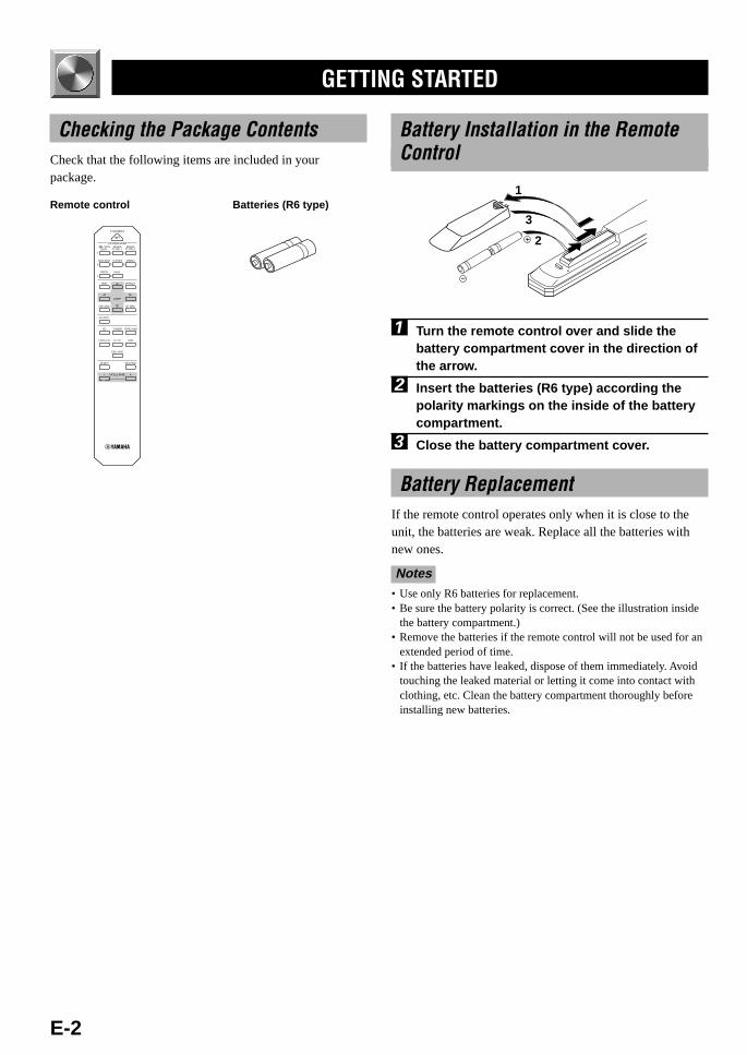
Remote control Batteries (R6 type)
GETTING STARTED
Battery Installation in the RemoteControl
1 Turn the remote control over and slide thebattery compartment cover in the direction ofthe arrow.
2 Insert the batteries (R6 type) according thepolarity markings on the inside of the batterycompartment.
3 Close the battery compartment cover.
Battery ReplacementIf the remote control operates only when it is close to theunit, the batteries are weak. Replace all the batteries withnew ones.
Notes• Use only R6 batteries for replacement.• Be sure the battery polarity is correct. (See the illustration inside
the battery compartment.)• Remove the batteries if the remote control will not be used for an
extended period of time.• If the batteries have leaked, dispose of them immediately. Avoid
touching the leaked material or letting it come into contact withclothing, etc. Clean the battery compartment thoroughly beforeinstalling new batteries.
2
1
3
Checking the Package ContentsCheck that the following items are included in yourpackage.
102.E800_01-06(Eng) 5/18/0, 1:36 PM2

E-3
English
BA
SIC
OP
ER
ATIO
NADVAN
CED
OPER
AT
ION
AP
PE
ND
IXIN
TR
OD
UC
TIO
NP
RE
PAR
ATIO
N
STANDBY/ON
INPUT MODE
INPUT SELECTORVOLUME
16
20
28
40
60
00 0
2
4
8
12
–dB
PROGRAMSET MENU EFFECTTAPE/MD MON
/6CH INPUT
NEXT+–
NATURAL SOUND AV PROCESSOR/AMPLIFIER DSP–E800 CINEMA DSP DOLBYD I G I T A L
D I G I T A L
SURROUND
Using the Remote Control
Remote controlsensor
Within approximately 6 m(20 feet)
The remote control transmits a directional infrared beam. Besure to aim the remote control directly at the infrared sensorduring operation. When the sensor is covered or there is alarge object between the remote control and the sensor, thesensor cannot receive signals. The sensor may not be able toreceive signals properly when it is exposed to direct sunlightor a strong artificial light (such as a fluorescent or strobelight). In this case, change the direction of the light orreposition the unit to avoid direct lighting.
Notes• Handle the remote control with care.• Do not spill water, tea or other liquids on the remote control.• Do not drop the remote control.• Do not leave or store the remote control in the following
conditions:– high humidity or temperature such as near a heater, stove or
bath;– dusty places; or– extremely low temperature.
GETTING STARTED
102.E800_01-06(Eng) 5/18/0, 1:36 PM3

E-4
CONTROLS AND FUNCTIONS
Front Panel
1 STANDBY/ONPress this switch to turn on the power of this unit or to setthis unit in the standby mode. Before turning the power on,set VOLUME to the “m” position.
Standby mode
In this mode, this unit consumes a very small quantity ofpower to receive infrared-signals from the remotecontrol.
2 Remote control sensorThis receives signals from the remote control.
3 DisplayThis shows various information. (Refer to page 5 fordetails.)
4 INPUT MODEPress this button to select the input mode among AUTO,DTS and ANALOG for the DVD/LD, D-TV and CBL/SATsources.
5 INPUT SELECTORTurn this selector to select the input source (TUNER, CD,VCR, CBL/SAT, D-TV, DVD/LD) that you want to listen toor watch. The arrow for the selected input source indicatorlights up on the display.
6 VOLUMETurn this control to turn up or down the volume.
7 SET MENU +/–Press these buttons to adjust the setting on the SET MENU.
8 NEXTPress this button to select the item on the SET MENU. Thisbutton functions like on the remote control when usingthe SET MENU.
9 TAPE/MD MON / 6CH INPUTPress this button to select a tape or an MD source. The“TAPE/MD MONITOR” indicator lights up on the display.When you press the button again, the “TAPE/MDMONITOR” indicator goes off, “6CH INPUT” appears onthe display and you can listen to a source connected to the6CH INPUT terminals.
0 EFFECTPress this button to turn on or off the effect speakers (centerand rear). If you turn them off, the signals of the center andrear channels are directed to the right and left main speakerswhen playing a source encoded with Dolby Digital andDTS. In this case, the output levels of the right and leftspeakers may not match.
q PROGRAM selectorPress l or h to select a DSP program when the effectspeakers (center and rear) are turned on. The name of theselected program appears on the display.
STANDBY/ON
INPUT MODE
INPUT SELECTORVOLUME
16
20
28
40
60
00 0
2
4
8
12
–dB
PROGRAMSET MENU EFFECTTAPE/MD MON
/6CH INPUT
NEXT+–
NATURAL SOUND AV PROCESSOR/AMPLIFIER DSP–E800 CINEMA DSP DOLBYD I G I T A L
D I G I T A L
SURROUND
1 2 3 4 5 6
q0987
102.E800_01-06(Eng) 5/18/0, 1:36 PM4

E-5
English
BA
SIC
OP
ER
ATIO
NADVAN
CED
OPER
AT
ION
AP
PE
ND
IXIN
TR
OD
UC
TIO
NP
RE
PAR
ATIO
NCONTROLS AND FUNCTIONS
Display
1 t indicatorThe “t” indicator lights up when the built-in DTSdecoder is on.
2 Multi-information displayThis display shows various information: for example thename of the selected DSP program and the various settingsduring adjustment with the SET MENU.
3 Input source indicatorsOne of the arrows for these indicators lights up dependingon which source is selected.
4 TAPE/MD MONITOR indicatorThis lights up when the tape deck or MD recorder, etc. isselected as the input source by pressing TAPE/MD MON /6CH INPUT (or TAPE/MD).
5 g and o indicators“ g ” lights up when the built-in Dolby Digitaldecoder is on. “ o ” lights up when the built-inDolby Pro Logic decoder is on.
6 x indicator“ x ” lights up when the built-in digital soundfield processor is on.
7 DSP program indicatorsThese indicators light up when DSP program No. 2, 3 or thesubprogram “ENHANCED” of No. 1 is selected.
8 SLEEP indicatorThis lights up while the built-in SLEEP timer is on.
DIGITAL
PRO LOGIC
DSP ENHANCED MOVIE THEATER 12
dBms
DVD/LDD–TVVCR
TUNERCDCBL/SATTAPE/MDMONITOR
SLEEP
4
8
32
765
1
102.E800_01-06(Eng) 5/18/0, 1:36 PM5

E-6
Remote Control
1 POWEREach time you press this button, the unit switches betweenthe power on and standby mode.
2 TESTPress this button to output the test tone for each speaker.
3 l (left), h (right)These buttons adjust the setting of the SET MENU andTIME/LEVEL mode.
4 TIME/LEVELPress this button to select the items in the TIME/LEVELmode.
5 6CH INPUTPress this button to select the source connected to the 6CHINPUT terminals.
6 SLEEPPress this button to set the SLEEP timer.
7 PROGRAM selector buttonsThese buttons select a DSP program.
8 EFFECTPress this button to turn on or off the effect speakers (centerand rear).
9 (next), (back)These buttons are used to advance or go back one selectionon the SET MENU and TIME/LEVEL mode.
0 SET MENUPress this button to select the items on the SET MENU.
q Input selector buttonsThese buttons select the input source.CD: To play a CDTUNER: To listen to an FM or AM broadcastTAPE/MD: To play a tape or MDDVD/LD: To play a DVD or LDD-TV: To watch a TVVCR: To play a video cassetteCBL/SAT: To watch cable TV or satellite broadcast
w MUTINGPress this button to mute the sound. To cancel mute, pressthis button again.
e VOLUME +/–These buttons are used to adjust the volume level.+: To turn up the volume–: To turn down the volume
CONTROLS AND FUNCTIONS
POWER
PROGRAM /DTS
SUR.
21
4
MOVIETHTR 1
3
MOVIETHTR 2
MONO MOVIE
7ROCK
TEST
TIME/LEVEL
6CH INPUT
SET MENU
5TV SPORTS
8HALL
6DISCO
EFFECT
DSP
CD TUNER TAPE/MD
DVD/LD D–TV VCR
CBL/SAT
SLEEP MUTING
+VOLUME–e
w
q
0
9
8
7
1
2
3
4
5
6
102.E800_01-06(Eng) 5/18/0, 1:36 PM6

E-7
English
BA
SIC
OP
ER
ATIO
NADVAN
CED
OPER
AT
ION
AP
PE
ND
IXIN
TR
OD
UC
TIO
NP
RE
PAR
ATIO
NPREPARATION
SPEAKER SETUP
Speaker PlacementRefer to the following diagram when you place thespeakers.
Main speakersPlace the right and left main speakers an equal distancefrom the ideal listening position. The distance of eachspeaker from each side of the TV monitor should be thesame.
Rear speakersPlace these speakers behind your listening position, facingslightly inwards, nearly 1.8 m (approx. 6 feet) above thefloor.
Center speakerAlign the front face of the center speaker with the front faceof your TV monitor. Place the speaker as close to themonitor as possible, such as directly over or under themonitor and centrally between the main speakers.
Note• If the center speaker is not used, the center channel sound will be
heard from the right and left main speakers. In that case,“CENTER SP” on the SET MENU is set to the NONE position.(Refer to page 26 for details.)
SubwooferThe position of the subwoofer is not so critical, because lowbass sounds are not highly directional. But it is better toplace the subwoofer near the main speakers. Turn it slightlytoward the center of the room to reduce the wall reflections.
CAUTION
Some types of speakers interfere with a TV monitor. Ifthis problem occurs, move the speakers away from themonitor. If you cannot avoid installing the center speakeror subwoofer near the TV monitor, use magneticallyshielded speakers.
Speakers to Be UsedThis unit is designed to provide the best sound-field qualitywith a 5-speaker system, using main speakers, rear speakersand a center speaker. If you use different brands of speakers(with different tonal qualities) in your system, the tone of amoving human voice and other types of sound may not shiftsmoothly. We recommend that you use speakers from thesame manufacture or speakers with the same tonal quality.
The main speakers are used for the main source sound plusthe effect sounds. They will probably be the speakers fromyour present stereo system. The rear speakers are used forthe effect and surround sounds, and the center speaker is forthe center sounds (dialog, vocals, etc.). If for some reason itis not practical to use a center speaker, you can do withoutit. Best results, however, are obtained with the full system.
The main speakers should be high-performance models andhave enough power-handling capacity to accept themaximum output of your audio system. The other speakersdo not have to be equal to the main speakers. For precisesound localization, however, it is ideal to use high-performance models that can reproduce sounds over the fullrange for the center speaker and the rear speakers.
Use of a subwoofer expands yoursound field
It is also possible to further expand your system with theaddition of a subwoofer. The use of a subwoofer is effectivenot only for reinforcing bass frequencies from any or allchannels, but also for reproducing the LFE (low frequencyeffect) channel with high fidelity when playing back asource encoded with Dolby Digital or DTS. The YAMAHAActive Servo Processing Subwoofer System is ideal fornatural and lively bass reproduction.
Subwoofer
Mainspeaker (L)
Center speakerRear speaker (L)
1.8 m
Rear speaker (R)
Main speaker (R)
103.E800_07-15(Eng) 5/18/0, 1:36 PM7

E-8
6CHINPUT
EXTERNALDECODER
MAIN IN
R
L
R
L
R
L
MAIN SURROUND CENTER
SUBWOOFER
DIGITAL SIGNAL
DVD/LD D–TV CBL/SAT DVD/LD CBL/SAT
OPTICAL COAXIAL
AUDIO SIGNAL
1 2 3 4CD TUNER TAPE/MD
IN (PLAY) OUT (REC)
DVD/LD D–TV CBL/SAT
IN
VCR
OUT
S VIDEO SIGNALDVD/LD D–TV CBL/SAT
IN OUT MONITOROUTVCR DVD/LD D–TV CBL/SAT
INVCR
OUT MONITOROUT
VIDEO SIGNAL
IMPEDANCE SELECTOR
SPEAKERS
CAUTION SEE INSTRUCTION MANUAL FOR CORRECT SETTING.
CENTER REAR(SURROUND)
+
–
R L
OUTPUT
R
L
MAIN REAR(SURROUND)
CENTER
SUBWOOFER
SET BEFORE POWER ON
REARCENTER
: 4ΩMIN./SPEAKER: 4ΩMIN./SPEAKER
REARCENTER
: 8ΩMIN./SPEAKER: 8ΩMIN./SPEAKER
AC OUTLET
SWITCHED100W MAX.
CONNECTIONS
Before Connecting Components
CAUTION
Never connect this unit and other components to mains power until all connections between components have beencompleted.
Be sure all connections are made correctly, that is to say L (left) to L, R (right) to R, “+” to “+” and “–” to “–”. Somecomponents require different connection methods and have different terminal names. Refer to the instructions for eachcomponent to be connected to this unit.
When you connect other YAMAHA audio components (such as a tape deck, MD recorder and CD player or changer), connectit to the terminals with the same number labels as !, @, #, $ etc. YAMAHA applies this labeling system to all itsproducts.
Use RCA-type pin plug cables for connecting audio/video components with the exception described later.
The input and output terminals for pin plugs can be distinguished as follows:
Yellow video signals (composite)
White analog audio signals for the left channel
Red analog audio signals for the right channel
coaxial digital signals
After completing all connections, check them again to make sure they are correct.
Connecting an AudioComponent (page 9)
L
R
L
R
C C
V V
IMPEDANCE SELECTORswitch (page 13)
Connecting the PowerSupply Cords (page 13)
Connecting theSpeakers (page 11)
Connecting to an ExternalDecoder (page 9)
Digital signal inputterminals (page 10)
To AC outlet
Connecting the ExternalAmplifier (page 11)
Connecting a VideoComponent (pages 10 and 11)
(Europe model)
103.E800_07-15(Eng) 5/18/0, 1:36 PM8

E-9
English
BA
SIC
OP
ER
ATIO
NADVAN
CED
OPER
AT
ION
AP
PE
ND
IXIN
TR
OD
UC
TIO
NP
RE
PAR
ATIO
N
Connecting an Audio Component
Be sure to connect the right channel (R), left channel (L),input (IN) and output (OUT) properly.
Connecting to an External DecoderThis unit has additional 6-channel audio signal inputterminals for connecting an external decoder to this unit. Setthe EXTERNAL DECODER/MAIN IN switch to theEXTERNAL DECODER position. Connect the 6-channelaudio signal output terminals of the decoder to the 6CHINPUT terminals of this unit.
CAUTION
Be sure to move the EXTERNAL DECODER/MAIN INswitch only when this unit is in the standby mode.
Notes• When a source connected to these terminals is selected, the digital
sound field processor cannot be used.• The settings of “CENTER SP”, “REAR SP”, “MAIN SP” and
“BASS OUT” on the SET MENU have no effect on a sourceconnected to these terminals. The setting of “MAIN LVL” iseffective. (Refer to pages 26 and 27 for details.)
• Adjustment of the output level of the center speaker, rear speakersand subwoofer is effective when a source connected to theseterminals is selected as the input source. (Refer to page 29 fordetails.)
6CHINPUT
EXTERNALDECODER
MAIN IN
R
L
R
L
MAIN SURROUND CENTER
SUBWOOFER
DIGITAL SIGNAL
DVD/LD D–TV CBL/SAT DVD/LD CBL/SA
OPTICAL COAXIAL
AUDIO SIGNAL
1 2 3 4CD TUNER TAPE/MD
IN (PLAY) OUT (REC)
DVD/LD D–TV CBL/SAT
IN
VCR
OUT
S VIDEO SIGNALDVD/LD D–TV CBL/SAT
IN OUT MONITOROUTVCR DVD/LD D–TV CBL/SAT
INVCR
OUT
VIDEO SIGNAL
L R L R
MAINOUT
SURROUNDOUT
CENTEROUT
SUBWOOFEROUT
EXTERNALDECODER
MAIN IN
External decoder
CONNECTIONS
6CHINPUT
EXTERNALDECODER
MAIN IN
R
L
MAIN SURROUND CENTER
SUBWOOFER
DIGITAL SIGNAL
DVD/LD D–TV CBL/SAT DVD/LD CBL/SAT
OPTICAL COAXIAL
AUDIO SIGNAL
1 2 3 4CD TUNER TAPE/MD
IN (PLAY) OUT (REC)
DVD/LD D–TV CBL/SAT
IN
VCR
OUT
S VIDEO SIGNALDVD/LD D–TV CBL/SAT
IN OUT MONITOROUTVCR DVD/LD D–TV CBL/SAT
INVCR
OUT MONITOROUT
VIDEO SIGNAL
R
L
R
L
LINE IN
L R
OUTPUT
L R
LINE OUT
L R
OUTPUT
L R
CD player
Tape deck orMD recorder
L
R
Analog signal
Signal flow
Tuner
EXTERNAL DECODER/MAIN IN switch
103.E800_07-15(Eng) 5/18/0, 1:36 PM9

E-10
DVD/LD D–TV CBL/SAT VCR
R
VIDEO SIGNALDVD/LD D–TV CBL/SAT
INVCR
OUT MONITOROUT
VIDEO IN
VV
VIDEOIN
VIDEOOUT
V
VIDEOOUT
V
V
VIDEO OUT
VV
VIDEOOUT
Connecting a Video Component
CONNECTIONS
Analog signal
Digital signal(optical)
Digital signal(coaxial)
Signal flow
Audio signal terminalsBe sure to connect the right channel (R), left channel (L),input (IN) and output (OUT) properly.
Note• Be sure to make the video connections as well.
Digital audio signal terminalsIf your DVD/LD player, TV/digital TV or cable TV/satellitetuner, etc. has coaxial or optical digital signal outputterminals, they can be connected to this unit’s COAXIALand/or OPTICAL digital signal input terminals. To make aconnection between the optical digital signal terminals,remove the cover from each terminal, and then connectthem by using a commercially available optical fiber cablethat conforms to EIA standards. Other cables might notfunction correctly.
When making connections between the digital signalterminals, you should connect the components to the same-named analog audio signal terminals of this unit, because adigital signal cannot be recorded by a tape deck, MDrecorder or VCR connected to this unit.
Notes• Be sure to attach the covers when the OPTICAL terminals are not
being used in order to protect them from dust.• If your LD player has a Dolby Digital RF signal output terminal,
be sure to use the RF demodulator (separately purchased).• No sound will be heard when connecting your LD player’s Dolby
Digital RF signal output terminal directly to this unit’s COAXIALDVD/LD digital signal input terminal.
y• The input signal from the DVD/LD or CBL/SAT input terminals
is selected in the following order of priority with the input modeset to AUTO: COAXIAL terminal → OPTICAL terminal →Analog terminal. Refer to page 18 for details.
• All digital signal input terminals are applicable to samplingfrequencies of 32 kHz, 44.1 kHz, 48 kHz and 96 kHz. (Refer topage 19 about 96-kHz sampling 24-bit digital signals.)
Video signal terminals (composite)If your video components do not have “S” video terminals,they can be connected to this unit’s VIDEO terminals. Besure to connect the input (IN) and output (OUT) properly.
Notes• Be sure to make the audio connections as well.• If video signals are input from both the S VIDEO input and
composite input terminals, the signals will be directed to theirrespective output terminals.
IN
R
L
MAIN SURROUND CENTER
SUBWOOFER
DIGITAL SIGNAL
DVD/LD D–TV CBL/SAT DVD/LD CBL/SAT
OPTICAL COAXIAL
AUDIO SIGNAL
1 2 3 4CD TUNER TAPE/MD
IN (PLAY) OUT (REC)
DVD/LD D–TV CBL/SAT
IN
VCR
OUT
R
L
R
L
AUDIOOUT
AUDIOIN
DIGITALSIGNAL(COAXIAL)
ANALOGAUDIO
OUT
ANALOGAUDIOOUT
DIGITALSIGNAL(OPTICAL)
O
DIGITALSIGNAL(OPTICAL)
DIGITALSIGNAL(OPTICAL)
O
DIGITAL SIGNAL(COAXIAL)
L R C
C
L R
L RL R
ANALOGAUDIO OUT
L R
O
VCR
DVD/LD playerCable TV/
satellite tuner
TV/Digital TV
L
R
C
O
Video signal
DVD/LD player
TV/Digital TV TV monitor
VCRCable TV/satellite tuner
Signal flow
103.E800_07-15(Eng) 5/18/0, 1:36 PM10

E-11
English
BA
SIC
OP
ER
ATIO
NADVAN
CED
OPER
AT
ION
AP
PE
ND
IXIN
TR
OD
UC
TIO
NP
RE
PAR
ATIO
N
IMPEDANCE
SET BEFORE
REARCENTER
: 4ΩM: 4ΩM
REARCENTER
: 8ΩM: 8ΩM
SPEAKERS
CAUTION SEE INSTRUCTION MANUAL FOR CORRECT SETTING.
CENTER REAR(SURROUND)
+
–
R L
OUTPUT
R
L
MAIN REAR(SURROUND)
CENTER
SUBWOOFER
R L
MAININ
L R
SubwoofersystemRear speakers
Main speakerRight
LeftRight
Center speaker
2-ch power amplifier
1 2 3 4
S VIDEO SIGNALDVD/LD D–TV CBL/SAT
IN OUT MONITOROUTVCR DV
S
SS
S VIDEO IN
S VIDEO OUT
S VIDEO OUT
S VIDEO IN
S VIDEO OUT
S
S
S
S VIDEO OUT
S
S VIDEO terminalsIf your video components have “S” (high-resolution) videoterminals, they can be connected to this unit’s S VIDEOterminals. Be sure to connect the input (IN) and output(OUT) properly.
Notes• Use a special S VIDEO cable (commercially available) for the S
VIDEO connection.• If video signals are input from both the S VIDEO input and
composite input terminals, the signals will be directed to theirrespective output terminals.
CONNECTIONS
DVD/LD player
TV Monitor
S Video signal
Signal flow
VCR
TV/Digital TVCable TV/satellite tuner
Main speakerLeft
Connecting the Speakers and the External Amplifier
Basic connectionIt is necessary to connect a 2-channel amplifier to this unitin order to drive main speakers.
Be sure to connect the right channel (R), left channel (L),“+” (red) and “–” (black) properly. If the connections arefaulty, no sound will be heard from the speakers, and if thepolarity of the speaker connections is incorrect, the soundwill be unnatural and lack bass.
Connecting 2-channel amplifierConnect the input terminals of a 2-ch power amplifier to theMAIN OUTPUT terminals of this unit. If you connect theAUX input terminals of the external amplifier to the MAINOUTPUT terminals of this unit, be sure to set the volume ofthe external amplifier around –16 dB to –18 dB.
Connecting a rear speaker systemConnect a rear speaker system to the REAR SPEAKER(SURROUND) output terminals of this unit.
Connecting a center speakerConnect a center speaker to the CENTER SPEAKER outputterminals of this unit.
Connecting a subwoofer systemConnect the input terminal of a subwoofer system to theSUBWOOFER OUTPUT terminal of this unit.
CAUTIONS
• Use speakers with the specified impedance shown onthe rear panel of this unit.
• Do not let the bare speaker wires touch each other anddo not let them touch any metal part of this unit. Thiscould damage the unit and/or speakers.
103.E800_07-15(Eng) 5/18/0, 1:36 PM11

E-12
Speaker cables
1 Remove approx. 10 mm (3/8”) of insulationfrom each of the speaker cables.
2 Twist the exposed wires of the cable togetherto prevent short circuits.
Connecting to the REAR andCENTER SPEAKERS terminals
1 Unscrew the knob.
2 Insert one bare wire into the hole in the side ofeach terminal.
3 Tighten the knob to secure the wire.
CONNECTIONS
1 2
10 mm (3/8”)
2
3
1Red: positive (+)Black: negative (–)
Other connections
Using this unit as a Dolby Digitalor DTS decoder
Connect the OUTPUT terminals (MAIN, REAR, CENTERand SUBWOOFER) of this unit to the EXTERNALDECODER or 6 CHANNEL input terminals of the externalamplifier.
Receiving the multi-channel signalfrom other equipment
1 Be sure to move the EXTERNAL DECODER/MAIN IN switch to the EXTERNAL DECODERposition before you turn on this unit.
2 Connect the OUTPUT terminal of the externalamplifier to the 6CH INPUT terminals of thisunit.
3 Press TAPE/MD MON / 6CH INPUT repeatedly(or 6CH INPUT once) until “6CH INPUT”appears on the display.• The signal on the main channel will be output to the
MAIN OUTPUT terminals.• The overall volume level will be controlled by DSP-
E800.
Using this unit as a poweramplifier
1 Be sure to move the EXTERNAL DECODER/MAIN IN switch to the MAIN IN position beforeyou turn on this unit.
2 Press TAPE/MD MON / 6CH INPUT repeatedly(or 6CH INPUT once) until “6CH INPUT”appears on the display.• DSP-E800 is regarded as 3-channel power amplifier.
The REAR L, the REAR R, and the CENTERterminals can be used for the connection.
• The volume control of this unit will be bypassed.
103.E800_07-15(Eng) 5/18/0, 1:37 PM12

E-13
English
BA
SIC
OP
ER
ATIO
NADVAN
CED
OPER
AT
ION
AP
PE
ND
IXIN
TR
OD
UC
TIO
NP
RE
PAR
ATIO
N
SET BEFORE POWER ON
REARCENTER
: 4ΩMIN./SPEAKER: 4ΩMIN./SPEAKER
REARCENTER
: 8ΩMIN./SPEAKER: 8ΩMIN./SPEAKER
AC OUTLET
SWITCHED100W MAX.
IMPEDANCE SELECTOR
Connecting the Power Supply CordsAfter completing all connections, connect the AC powercord to an AC power outlet. Disconnect the AC power cordif you will not use this unit for a long period of time.
AC OUTLET (SWITCHED)U.K. and Europe models .................................... 1 OUTLETUse this outlet to connect the power cords from yourcomponents to this unit. The power to the AC OUTLET iscontrolled by this unit’s STANDBY/ON (or POWER). Thisoutlet will supply power to any connected componentwhenever this unit is turned on. The maximum power (totalpower consumption of components) that can be connectedto the AC OUTLET is 100 W.
IMPEDANCE SELECTOR Switch
WARNING
Do not change the IMPEDANCE SELECTOR switch setting while the power of this unit is on, otherwise the unit may bedamaged.If this unit fails to turn on when STANDBY/ON (POWER) is pressed, the IMPEDANCE SELECTOR switch may not befully slide to either position. If so, slide the switch to either position fully when this unit is in the standby mode.
Select the right or left position according to the impedance of speakers in your system. Be sure to move this switch onlywhen this unit is in the standby mode.
(Europe model)
SET BEFORE POWER ON
REARCENTER
: 4ΩMIN./SPEAKER: 4ΩMIN./SPEAKER
REARCENTER
: 8ΩMIN./SPEAKER: 8ΩMIN./SPEAKER
AC OUTLET
SWITCHED100W MAX.
IMPEDANCE SELECTOR
SWITCHED
(Europe model)
To AC outlet
IMPEDANCESELECTOR
CONNECTIONS
Switch potision
Left
Right
Speakers Impedance level
Rear
Center
Rear
The impedance of each speaker must be4 Ω or higher.
The impedance must be 4Ω or higher.
The impedance of each speaker must be8 Ω or higher.
The impedance must be 8Ω or higher.Center
103.E800_07-15(Eng) 5/18/0, 1:37 PM13

E-14
1 Set VOLUME to the “ m”position.
2 Turn the power on.
3 Press TEST.“TEST LEFT” appears on the display.
4 Turn up the volume.You will hear a test tone (like pink noise) from eachspeaker for about two seconds in the following order:left main speaker, center speaker, right main speaker,right rear speaker and left rear speaker. The displaychanges as shown below.
Notes• If the test tone cannot be heard, turn down the volume, set the unit
in the standby mode and check the speaker connections.• If the test tone cannot be heard from the center speaker, check the
setting of “CENTER SP” on the SET MENU.
This procedure lets you adjust the sound output levelbalance between the main, center and rear speakers by usingthe built-in test tone generator. When this adjustment isperformed, the sound output level heard at the listeningposition will be the same from each speaker. This isimportant for the best performance of the digital sound fieldprocessor, the Dolby Pro Logic decoder, Dolby Digitaldecoder and DTS decoder.
The adjustment of each speaker sound output level shouldbe performed at your listening position with the remotecontrol. After completing the adjustments, use VOLUME+/– at your listening position to check if the adjustments aresatisfactory.
ADJUSTING THE SPEAKER BALANCE
STANDBY/ON
INPUT MODE
INPUT SELECTORVOLUME
16
20
28
40
60
00 0
2
4
8
12
–dB
PROGRAMSET MENU EFFECTTAPE/MD MON
/6CH INPUT
NEXT+–
NATURAL SOUND AV PROCESSOR/AMPLIFIER DSP–E800 CINEMA DSP DOLBYD I G I T A L
D I G I T A L
SURROUND
2 1
VOLUME16
20
28
40
60
00 0
2
4
8
12
–dB
STANDBY/ON
POWER
PROGRAM /DTS
SUR.
21
4
MOVIETHTR 1
3
MOVIETHTR 2
MONO MOVIE
7ROCK
TEST
TIME/LEVEL
6CH INPUT
SET MENU
5TV SPORTS
8HALL
6DISCO
EFFECT
DSP
CD TUNER TAPE/MD
CD TUNER TAPE/MD
DVD/LD D–TV VCR
CBL/SAT
SLEEP MUTING
+VOLUME–3,7
2
5 6
4
TEST
TEST LEFT
TEST RIGHT
TEST L SUR. TEST R SUR.
TEST CENTER
POWER
Front panel Remote control
or
Front panel
+VOLUME–
103.E800_07-15(Eng) 5/18/0, 1:37 PM14
E-15
English
BA
SIC
OP
ER
ATIO
NADVAN
CED
OPER
AT
ION
AP
PE
ND
IXIN
TR
OD
UC
TIO
NP
RE
PAR
ATIO
N
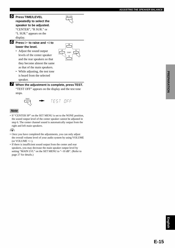
TIME/LEVEL5 Press TIME/LEVELrepeatedly to select thespeaker to be adjusted.“CENTER”, “R SUR.” or“L SUR.” appears on thedisplay.
6 Press h to raise and l tolower the level.• Adjust the sound output
levels of the center speakerand the rear speakers so thatthey become almost the sameas that of the main speakers.
• While adjusting, the test toneis heard from the selectedspeaker.
7 When the adjustment is complete, press TEST.“TEST OFF” appears on the display and the test tonestops.
Note• If “CENTER SP” on the SET MENU is set to the NONE position,
the sound output level of the center speaker cannot be adjusted instep 6. The center channel sound is automatically output from theright and left main speakers.
y• Once you have completed the adjustments, you can only adjust
the overall volume level of your audio system by using VOLUME(or VOLUME +/–).
• If there is insufficient sound output from the center and rearspeakers, you may decrease the main speaker output level bysetting “MAIN LVL” on the SET MENU to “–10 dB”. (Refer topage 27 for details.)
DSP
TEST
ADJUSTING THE SPEAKER BALANCE
103.E800_07-15(Eng) 5/18/0, 1:37 PM15

E-16
1 Set VOLUME to the “ m”position.
2 Turn the power on.
3 Select the desired inputsource with INPUTSELECTOR (or the inputselector buttons). (Turn onthe TV monitor for videosources.)The name of the selected inputsource appears for a momentand the arrow for the selectedinput source indicator lights upon the display.
PLAYING A SOURCE
BASIC OPERATION
a. To select a tape or an MD sourcePress TAPE/MD MON / 6CH INPUT (or TAPE/MD)so that the “TAPE/MD MONITOR” indicator lights upon the display.
b. To select a source connected to the 6CHINPUT terminalsPress TAPE/MD MON / 6CH INPUT repeatedly (or6CH INPUT) until “6CH INPUT” appears on thedisplay.
Notes• If the “TAPE/MD MONITOR” indicator lights up or “6CH
INPUT” is shown on the display, no other audio source except atape/MD source and a source connected to the 6CH INPUTterminals can be played. To select another input source withINPUT SELECTOR (or the input selector buttons):– Press TAPE/MD MON / 6CH INPUT twice (or TAPE/MD
once) to turn off the “TAPE/MD MONITOR” indicator.– Press TAPE/MD MON / 6CH INPUT once (or 6CH INPUT) to
turn off “6CH INPUT”.• If you select and play a video source when the “TAPE/MD
MONITOR” indicator lights up, the play back result will be avideo image from the video source and the sound from the audiosource connected to the TAPE/MD IN (PLAY) terminals.
• A video source cannot be selected when “6CH INPUT” is shownon the display. If you want to enjoy an audio source connected tothe 6CH INPUT terminals together with a video source, firstselect the video source and then select the source connected to the6CH INPUT terminals.
yFor the DVD/LD, D-TV and CBL/SAT sources, the current inputmode is also shown. Refer to page 18 for details about the inputmode.
Front panel
Front panel Remote control
or
INPUT SELECTOR
Front panelor
CD TUNER TAPE/MD
DVD/LD D–TV VCR
CBL/SAT
Remote control
DVD/LDD–TVVCR
TUNERCDCBL/SAT
Input source
TAPE/MD MON
/6CH INPUT
Front panel
POWER
PROGRAM /DTS
SUR.
21
4
MOVIETHTR 1
3
MOVIETHTR 2
MONO MOVIE
7ROCK
TEST
TIME/LEVEL
6CH INPUT
SET MENU
5TV SPORTS
8HALL
6DISCO
EFFECT
DSP
CD TUNER TAPE/MD
CD TUNER TAPE/MD
DVD/LD D–TV VCR
CBL/SAT
SLEEP MUTING
+VOLUME–
3
5
2
6
3
VOLUME16
20
28
40
60
00 0
2
4
8
12
–dB
STANDBY/ON
POWER
STANDBY/ON
INPUT MODE
INPUT SELECTORVOLUME
16
20
28
40
60
00 0
2
4
8
12
–dB
PROGRAMSET MENU EFFECTTAPE/MD MON
/6CH INPUT
NEXT+–
NATURAL SOUND AV PROCESSOR/AMPLIFIER DSP–E800 CINEMA DSP DOLBYD I G I T A L
D I G I T A L
SURROUND
2
6
3 1,5
orTAPE/MD
Remote control
DVD/LDD–TVVCR
TUNERCDCBL/SATTAPE/MDMONITOR
DVD/LDD–TVVCR
TUNERCDCBL/SAT
TAPE/MD MON
/6CH INPUT
Front panel
or6CH INPUT
Remote control
Lights up
104.E800_16-20(Eng) 5/18/0, 1:37 PM16

E-17
English
BA
SIC
OP
ER
ATIO
NADVAN
CED
OPER
AT
ION
AP
PE
ND
IXIN
TR
OD
UC
TIO
NP
RE
PAR
ATIO
N
4 Play the source.Refer to the instructions for the source component.
5 Adjust the volume to the desired output level.
6 Use the digital sound field processor.Refer to page 20.
PLAYING A SOURCE
VOLUME16
20
28
40
60
00 0
2
4
8
12
–dB
Front panel Remote control
or+VOLUME–
PROGRAM
Front panel Remote control
PROGRAM /DTS
SUR.
21
4
MOVIETHTR 1
3
MOVIETHTR 2
MONO MOVIE
7ROCK
5TV SPORTS
8HALL
6DISCO
or
MUTING
To mute the soundPress MUTING on theremote control so that“MUTE ON” appears on thedisplay.To cancel mute, press MUTING again so that“MUTE OFF” appears for a moment on the display.
When you have finished using thisunitPress STANDBY/ON (or POWER) to set thisunit in the standby mode.
BGV (background video) functionThe BGV function allows you to combine a video imagefrom a video source with a sound from an audio source.(For example, you can listen to classical music while youare watching a video.) This function can only be controlledwith the remote control.
Play a video source, and then select an audio source withthe input selector buttons on the remote control. The BGVfunction does not work if you select the audio source withINPUT SELECTOR on the front panel.
104.E800_16-20(Eng) 5/18/0, 1:37 PM17

E-18
Switching the input modePress INPUT MODE (or the input selectorbutton that you have pressed to select theinput source on the remote control) repeatedlyuntil the desired input mode is shown on thedisplay.
Notes• Set the input mode to AUTO to play a DVD/LD source encoded
with Dolby Digital.• If the input mode is set to AUTO for the source, this unit
automatically determines which type of signal the sourcecontains. If this unit detects a Dolby Digital or DTS signal, thedecoder automatically switches to the appropriate setting andreproduces 5.1 channel sound.
• The sound output may be interrupted for some LD and DVDplayers in the following situation: The input mode is set to AUTO.A search is performed while playing the disc encoded with DolbyDigital or DTS, and then disc playing is restored. The soundoutput is interrupted for a moment because the digital signal wasselected again.
• The input mode cannot be changed for the CD, TUNER, TAPE/MD and VCR sources because only analog signals are used forthese.
• The current input mode appears on the display when the DVD/LD, D-TV or CBL/SAT source is selected or the input mode ischanged.
INPUT MODE
Front panel
CD TUNER TAPE/MD
DVD/LD D–TV VCR
CBL/SAT
Remote control
or
DVD/LDD–TVVCR
TUNERCDCBL/SAT
Input Mode (for the DVD/LD, D-TVand CBL/SAT sources)
This unit allows you to switch the input mode for sourcesthat send both digital and analog signals to this unit. TheAUTO, DTS and ANALOG input modes are provided.
When you turn on the power of this unit, the input mode forthe DVD/LD source is always set to AUTO and for D-TV orCBL/SAT source is set according to “TV INPUT” and“CBL INPUT” on the SET MENU. (Refer to page 28 fordetails.)
AUTOIn this mode, the input signal is selected in the followingorder of priority:1. Digital signal encoded with Dolby Digital or DTS2. Normal digital signal (PCM)3. Analog signal (ANALOG)
Note• If digital signals are input from both the OPTICAL and
COAXIAL terminals, the digital signal from the COAXIALterminal is selected.
DTSIn this mode, only a digital signal encoded with DTS isselected, even if other signals are being input at the sametime.
ANALOGIn this mode, only an analog signal is selected, even if adigital signal is being input at the same time. Select thismode when you want to use an analog signal instead of adigital signal.
PLAYING A SOURCE
Input mode
104.E800_16-20(Eng) 5/18/0, 1:37 PM18

E-19
English
BA
SIC
OP
ER
ATIO
NADVAN
CED
OPER
AT
ION
AP
PE
ND
IXIN
TR
OD
UC
TIO
NP
RE
PAR
ATIO
N
Notes on playing a sourceencoded with DTS
• If “DATA ERROR” appears on the display while playing an LDsource encoded with DTS, stop playback and turn the player offand then on again.
• If the digital output data of the player has been processed in anyway, you may not be able to perform DTS decoding even if youmake a digital connection between this unit and the player.
• If you play an LD source encoded with DTS and set the inputmode to ANALOG, there will be the noise of an unprocessedDTS signal. When you want to play a DTS source, be sure toconnect the source to the digital input terminal and set the inputmode to AUTO or DTS.
• If you play a source encoded with DTS and set the input mode toAUTO, there will be a short noise at first while the unitrecognizes the DTS signal and turns on the DTS decoder. This isnot a malfunction, and can be avoided by setting the input modeto DTS beforehand. In addition, if you continue to play a sourceencoded with DTS with the input mode setting left to AUTO, thisunit automatically switches to the “DTS-decoding” mode toprevent noise from being generated during subsequent operation.(The “t” indicator lights up on the display.) The “t”indicator will flash immediately after playback of a sourceencoded with DTS has finished. Only a source encoded with DTScan be played back while this indicator is flashing. If you want toplay a normal PCM source soon, set the input mode back toAUTO.
PLAYING A SOURCE
Notes on playing an LD source• Some audio/video component, such as LD player, output different
audio signals through their analog and digital terminals. Changethe input mode as necessary.
• If the LD player is transmitting signals by a non-normal method,this unit cannot detect the Dolby Digital or DTS signal. In thiscase, the decoder automatically switches to PCM or analog.
• If the LD source does not contain a digital soundtrack, connectthe LD player to the analog terminals and set the input mode toAUTO or ANALOG.
• While you are operating the LD player and playing a disc encodedwith Dolby Digital, if you switch from the pause or chapterforwarding function to normal playback, you may hear the PCMor analog sound an instant before the Dolby Digital sound isplayed.
Notes on the digital signalThe digital input terminal of this unit can also handle96-kHz sampling 24-bit digital signals. (To utilize this, use asource that supports 96-kHz sampling 24-bit digital signalsand set the player for digital output. Refer to the instructionsfor the player.) Note the following when a 96-kHz sampling24-bit digital signal is input to this unit.1. The following indicator will appear on the display.
2. DSP programs cannot be selected. Sound will be outputas normal 2-channel stereo sound using only the rightand left main speakers.
3. Delay time and speaker output level cannot be adjusted.
DVD/LDD–TVVCR
TUNERCDCBL/SAT
104.E800_16-20(Eng) 5/18/0, 1:37 PM19

E-20
DIGITAL SOUND FIELD PROCESSOR (DSP) EFFECT
Selecting a DSP ProgramYou can enhance your listening experience by selecting aDSP program. Refer to pages 22 to 24 for details about eachprogram.
1 Make sure that the effect speakers (center andrear) and subwoofer are turned on.
2 Press PROGRAM l or h repeatedly (or one ofthe PROGRAM selector buttons) to select thedesired program.The name of the selected program appears on thedisplay.
yIf desired, adjust the delay time and the sound output level of eachspeaker. (Refer to pages 29 and 30 for details.)
Notes• You can select a DSP program for each of the input sources. Once
you select a program, it is linked with the input source selected atthat time. So, when you select the input source next time, thesame program is automatically selected.
• When a monaural source is being played with PRO LOGIC/Normal or PRO LOGIC/ENHANCED, no sound will be heardfrom the main speakers and the rear speakers. Sound can only beheard from the center speaker. However, if “CENTER SP” on theSET MENU is set to the NONE position, the center channelsound is output from the main speakers.
• When a source connected to the 6CH INPUT terminals of thisunit is selected, the digital sound field processor cannot be used.
• When high-rate 96-kHz sampling 24-bit digital signals are inputto this unit, no DSP program can be selected and the sound is onlyoutput from right and left main speakers as a normal 2-channelstereo sound.
PROGRAM
PRO LOGIC
DSP MOVIE THEATER 2
DVD/LDD–TVVCR
TUNERCDCBL/SAT
PROGRAM /DTS
SUR.
21
4
MOVIETHTR 1
3
MOVIETHTR 2
MONO MOVIE
7ROCK
5TV SPORTS
8HALL
6DISCO
Canceling the Sound Effect (turningoff the effect speakers)
Press EFFECT to cancel the sound effect andmonitor only the main sound.Press EFFECT again to turn the sound effect back on.
Notes• If you turn off the sound effect when Dolby Digital or DTS is
decoding, the sounds of the center and rear channels are mixedand output from the main speakers.
• If you turn off the sound effect when Dolby Digital or DTS isdecoding, it may happen that the sound is output faintly or notoutput normally, depending on the source. In this case, turn soundeffect back on.
EFFECT
Front panel
EFFECT
Remote control
STANDBY/ON
INPUT MODE
INPUT SELECTORVOLUME
16
20
28
40
60
00 0
2
4
8
12
–dB
PROGRAMSET MENU EFFECTTAPE/MD MON
/6CH INPUT
NEXT+–
NATURAL SOUND AV PROCESSOR/AMPLIFIER DSP–E800 CINEMA DSP DOLBYD I G I T A L
D I G I T A L
SURROUND
2
POWER
PROGRAM /DTS
SUR.
21
4
MOVIETHTR 1
3
MOVIETHTR 2
MONO MOVIE
7ROCK
TEST
TIME/LEVEL
6CH INPUT
SET MENU
5TV SPORTS
8HALL
6DISCO
EFFECT
DSP
CD TUNER TAPE/MD
2
Front panel Remote control
or
DSP program name
or
104.E800_16-20(Eng) 5/18/0, 1:37 PM20

E-21
English
BA
SIC
OP
ER
ATIO
NADVAN
CED
OPER
AT
ION
AP
PE
ND
IXIN
TR
OD
UC
TIO
NP
RE
PAR
ATIO
N
RECORDING A SOURCE ON TAPE, MD OR VIDEO CASSETTE
Recording adjustments and other operations are performedfrom the tape deck, MD recorder or VCR. Refer to theinstructions for these components.
1 Set VOLUME to the “ m”position.
2 Select the source you want to record.
3 Begin recording by the tape deck, MD recorderor VCR connected to this unit.
4 Play the source and then turn up the volume toconfirm the input source.
Front panel
Front panel
or
Remote control
Remote control
or
Front panel
VOLUME16
20
28
40
60
00 0
2
4
8
12
–dB
INPUT SELECTOR CD TUNER
DVD/LD D–TV VCR
CBL/SAT
VOLUME16
20
28
40
60
00 0
2
4
8
12
–dB
+VOLUME–
yIf a tape deck or MD recorder is being used for recording, you canmonitor the sounds being recorded by pressing TAPE/MD MON /6CH INPUT (or TAPE/MD).
Notes• The DSP program and the setting of VOLUME have no effect on
the material being recorded.• Composite video and S video signals pass independently through
this unit’s video circuits. Therefore, when recording or dubbingvideo signals, if your video source component is connected toprovide only an S video (or only a composite video) signal, youcan record only an S video (or only a composite video) signal byyour VCR.
• A source connected to this unit only through the digital terminalscannot be recorded by the tape deck, MD recorder or VCRconnected to this unit.
• A source connected to the 6CH INPUT terminals of this unitcannot be recorded.
• Check the copyright laws in your country to record from records,CDs, radio, etc. Recording of copyrighted material may infringecopyright laws.
If you play back a video source that uses scrambled orencoded signals to prevent it from being dubbed, thepicture itself may be disturbed due to those signals.
STANDBY/ON
INPUT MODE
INPUT SELECTORVOLUME
16
20
28
40
60
00 0
2
4
8
12
–dB
PROGRAMSET MENU EFFECTTAPE/MD MON
/6CH INPUT
NEXT+–
NATURAL SOUND AV PROCESSOR/AMPLIFIER DSP–E800 CINEMA DSP DOLBYD I G I T A L
D I G I T A L
SURROUND
2 1,4
6CH INPUT
CD TUNER TAPE/MD
DVD/LD D–TV VCR
CBL/SAT
SLEEP MUTING
+VOLUME–
2
4
105.E800_21(Eng) 5/18/0, 1:37 PM21

E-22
SOUND FIELD PROGRAM
This unit incorporates a sophisticated, multi-program digital sound field processor (DSP). This processor allows you toelectronically expand and change the shape of the audio sound field from both audio and video sources, creating a theater-like experience in your listening room. You can create outstanding audio sound by selecting a suitable DSP program (thiswill, of course, depend on what you are listening to).
When you select a CINEMA DSP program, one of the built-in decoders (Dolby Pro Logic, Dolby Digital and DTS) is turnedon according to which type of signals the source being played contains.
The following list gives you a brief description of the sound fields produced by each of the DSP programs. Keep in mind thatmost of these are precise digital re-creations of actual acoustic environments.
• The input source given in the following table for programs 4 through 8 indicates that input source which each programis best suited for.
• Select the DSP program that you feel sounds best regardless of the name and description given for it below.
For movie or audio/video sources (Program No. 1 to No. 5: CINEMA DSPprograms)
[1] PRO LOGIC/Normal ( o )• Input source: Dolby Surround
2-ch Dolby Digital• Output channel: 4 channels• DSP: —[2] DOLBY DIGITAL/Normal ( g )• Input source: Dolby Digital• Output channel: 5.1 channels• DSP: —[3] DTS DGTL SUR/Normal ( t )• Input source: DTS• Output channel: 5.1 channels• DSP: —
[4] PRO LOGIC/ENHANCED(ox )
• Input source: Dolby Surround2-ch Dolby Digital
• Output channel: 4 channels• DSP: 1 (surround)[5] DOLBY DIGITAL/ENHANCED
(gx )• Input source: Dolby Digital• Output channel: 5.1 channels• DSP: 2 (surround L, R)[6] DTS DGTL SUR/ENHANCED
(tx )• Input source: DTS• Output channel: 5.1 channels• DSP: 2 (surround L, R)
This program ideally simulates the multi-surround speaker systems of the 35 mm-filmmovie theater. Dolby Pro Logic decoding,Dolby Digital decoding or DTS decoding anddigital sound field processing are preciselyperformed without altering the original soundorientation.The surround effect produced by the soundfield folds around the viewer naturally fromthe rear to the right and left and toward thescreen.
The built-in Dolby Pro Logic decoder, DolbyDigital decoder or DTS decoder preciselyreproduces the sound and effect of a sourceencoded with Dolby Surround, Dolby Digitalor DTS.The realization of a highly efficient decodingprocess improves cross talk and channelseparation, and makes sound positioningsmoother and more precise.In this program, the digital sound fieldprocessor is not turned on.
1 q/DTSSURROUND
No. PROGRAM SUBPROGRAM FEATURES
TEST
TIME/LEVEL SET MENU
EFFECT
DSP
ADVANCED OPERATION
106.E800_22-24(Eng) 5/18/0, 1:37 PM22

E-23
English
BA
SIC
OP
ER
ATIO
NADVAN
CED
OPER
AT
ION
AP
PE
ND
IXIN
TR
OD
UC
TIO
NP
RE
PAR
ATIO
NSOUND FIELD PROGRAM
This program creates the extremely wide soundfield of a movie theater. It precisely reproducesthe source sound in detail, giving both the videoand the sound field incredible reality. It is idealfor any kind of video source encoded withDolby Surround, Dolby Digital or DTS(especially large-scale movie productions).
[1] 70 mm SPECTACLE(ox )
• Input source: Dolby Surround2-ch Dolby Digital
• Output channel: 3 channels• DSP: 2 (presence & surround)[2] DGTL SPECTACLE
( g x )• Input source: Dolby Digital• Output channel: 5.1 channels• DSP: 3 (presence & surround L, R)[3] DTS SPECTACLE ( tx )• Input source: DTS• Output channel: 5.1 channels• DSP: 3 (presence & surround L, R)
[4] 70 mm SCI-FI ( o x )• Input source: Dolby Surround
2-ch Dolby Digital• Output channel: 3 channels• DSP: 2 (presence & surround)[5] DGTL SCI-FI ( g x )• Input source: Dolby Digital• Output channel: 5.1 channels• DSP: 3 (presence & surround L, R)[6] DTS SCI-FI ( t x )• Input source: DTS• Output channel: 5.1 channels• DSP: 3 (presence & surround L, R)
[1] 70 mm ADVENTURE(ox )
• Input source: Dolby Surround2-ch Dolby Digital
• Output channel: 3 channels• DSP: 2 (presence & surround)[2] DGTL ADVENTURE
(gx )• Input source: Dolby Digital• Output channel: 5.1 channels• DSP: 3 (presence & surround L, R)[3] DTS ADVENTURE ( t x )• Input source: DTS• Output channel: 5.1 channels• DSP: 3 (presence & surround L, R)
[4] 70 mm GENERAL ( ox )• Input source: Dolby Surround
2-ch Dolby Digital• Output channel: 3 channels• DSP: 2 (presence & surround)[5] DGTL GENERAL ( gx )• Input source: Dolby Digital• Output channel: 5.1 channels• DSP: 3 (presence & surround L, R)[6] DTS GENERAL ( t x )• Input source: DTS• Output channel: 5.1 channels• DSP: 3 (presence & surround L, R)
Clearly reproduces dialog and sound effects inthe latest sound form of science fiction films,thus creating a broad and expansive cinematicspace amid the silence. You can enjoy sciencefiction films in a virtual-space sound field thatincludes Dolby Surround, Dolby Digital andDTS-encoded software employing the mostadvanced techniques.
2 MOVIETHEATER 1
3 MOVIETHEATER 2
Ideal for precisely reproducing the sound of thenewest multi-track films. The sound field ismade to be similar to that of the newest movietheaters, so the reverberations of the sound fielditself are restrained as much as possible. Thedata for the sound field of an opera house areused for the front presence, so the three-dimensional feeling of the sound field isemphasized, and dialog is precisely oriented onthe screen. By using the data for the sound fieldof a concert hall on the surround sound field,powerful reverberations are generated. You canenjoy watching action, adventure movies, etc.with strong presence.
This program is for reproducing sounds on amulti-track film, and is characterized by a softand extensive sound field. The front presence ofthe sound field is relatively narrow. It spatiallyspreads all around and toward the screen,restraining echo effect of conversations withoutlosing clarity. For the surround sound field, theharmony of music or chorus sounds beautifullyin a wide space at the rear of the sound field.
No. PROGRAM SUBPROGRAM FEATURES
106.E800_22-24(Eng) 5/18/0, 1:37 PM23

E-24
CINEMA DSP: Dolby Surround + DSP/Dolby Digital + DSP/DTS + DSP
Dolby Pro Logic + 2 digital sound fieldsDigital sound fields are created in both the presence andrear surround zones of the Dolby Pro Logic-decoded soundfield. They create a wide acoustic environment andemphasize the surround effect in the room, letting you feelas much presence as if you were watching a movie in apopular Dolby Stereo theater.
Dolby Digital or DTS + 3 digital sound fieldsDigital sound fields are created in the presence zone andindependently on the left and right surround zones of theDolby Digital-decoded or DTS-decoded sound field. Theycreate a wide acoustic environment and strong surroundeffect in the room without losing high channel separation.With the wide dynamic range of Dolby Digital or DTSsound, this sound field combination lets you feel as if youwere watching a movie in the newest Dolby Digital theateror DTS-installed theater. This is the most ideal home theatersound at the present time.
SOUND FIELD PROGRAM
This program is designed specifically to enhance monauralsources. Compared to a strictly mono setting, the sound imageis wider and slightly forward of the speaker pair, lending animmediacy to the overall sound. It is particularly effective forold mono movie, news broadcasts and dialog.
4 MONO MOVIE ( x )• Input source: Monaural• Output channel: 1 channel• DSP: 1
No. PROGRAM FEATURES
This program is furnished with a tight sound field in which thesound will not spread excessively at the front, but the rearsurround produces dynamic sound expansion. It is the mostsuitable for sports programs.
5 TV SPORTS ( x )• Input source: Audio/Video• Output channel: 2 to 5.1 channels• DSP: 2 to 3 (presence & surround)
For Hi-Fi audio sources
No. PROGRAM FEATURES
This program creates the expansive ambience of a large concerthall. It is suited for orchestra and opera music.
This program simulates the acoustic environment of a disco inthe heart of a lively city. The sound is dense and highlyconcentrated.
This program is ideally suited for rock music. You willexperience a dynamic and lively sound field.
6 DISCO ( x )• Input source: 2-ch PCM/Analog audio• Output channel: 2 channels• DSP: 1
7 ROCK CONCERT ( x )• Input source: 2-ch PCM/Analog audio• Output channel: 2 channels• DSP: 1
8 CONCERT HALL ( x )• Input source: 2-ch PCM/Analog audio• Output channel: 2 channels• DSP: 1
106.E800_22-24(Eng) 5/18/0, 1:37 PM24

E-25
English
BA
SIC
OP
ER
ATIO
NADVAN
CED
OPER
AT
ION
AP
PE
ND
IXIN
TR
OD
UC
TIO
NP
RE
PAR
ATIO
N
TEST
TIME/LEVEL SET MENU
EFFECT
DSP
This unit provides you with the following items on the SETMENU to maximize the performance of your system andexpand your enjoyment for audio listening and videowatching.
1. CENTER SP2. REAR SP3. MAIN SP4. BASS OUT5. MAIN LVL6. D.D. LFE7. D-RANGE8. DTS LFE9. CNTR DELAY10.MEM. GUARD11.TV INPUT12.CBL INPUT
Adjusting Items in the SET MENUAdjustments should be performed while watching theinformation on the display.
1 Press NEXT (or SET MENU) repeatedly toselect the item you want to adjust.The selected item appears on the display.
yAfter pressing NEXT (or SET MENU) once, you can also select theitem by pressing . (Pressing goes back one selection.)
2 Press SET MENU +/– (or l or h) repeatedly toadjust the setting.
3 Repeat steps 1 and 2 to adjust the setting ofany other item in the same way.
Memory back-up
The memory back-up circuit prevents the stored datafrom being lost when this unit is set in the standby mode.If, however, the power cord is disconnected from the ACpower outlet or the power is cut for more than one week,the settings of the SET MENU will automatically returnto the preset positions and values. If so, adjust thesettings of the SET MENU again.
DVD/LDD–TVVCR
TUNERCDCBL/SAT
SET MENU
STANDBY/ON
INPUT MODE
INPUT SELECTORVOLUME
16
20
28
40
60
00 0
2
4
8
12
–dB
PROGRAMSET MENU EFFECTTAPE/MD MON
/6CH INPUT
NEXT+–
NATURAL SOUND AV PROCESSOR/AMPLIFIER DSP–E800 CINEMA DSP DOLBYD I G I T A L
D I G I T A L
SURROUND
2 1
POWER
PROGRAM /DTS
SUR.
21
4
MOVIETHTR 1
3
MOVIETHTR 2
MONO MOVIE
7ROCK
TEST
TIME/LEVEL
6CH INPUT
SET MENU
5TV SPORTS
8HALL
6DISCO
EFFECT
DSP
CD TUNER TAPE/MD
21
NEXT SET MENU
Front panel Remote control
or
SET MENU +–
DSP
Front panel Remote control
or
DVD/LDD–TVVCR
TUNERCDCBL/SAT
107.E800_25-31(Eng) 5/18/0, 1:37 PM25

E-26
SET MENU
Description of Each Item
1. CENTER SPChoices: LRG (Large)/SML (Small)/NONEPreset position: LRG (Large)
LRG (Large)Select this position if your center speaker is approximatelythe same size as the main speakers. In this position, full-range signals on the center channel are directed to the centerspeaker.
SML (Small)Select this position if you use a center speaker that issmaller than the main speakers. In this position, low basssignals (below 90 Hz) on the center channel are distributedto the SUBWOOFER OUTPUT terminal (or to the right andleft main speakers if “BASS OUT” is set to the MAINposition).
NONESelect this position if you do not have a center speaker(4-speaker system). In this position, full-range signals onthe center channel are directed to the right and left mainspeakers.
2. REAR SPChoices: LARGE/SMALLPreset position: LARGE
LARGESelect this position if your rear speakers have high abilityfor bass reproduction, or if a subwoofer is connected inparallel to the rear speaker. In this position, full-rangesignals on the rear channels are directed to the rear speakers.
SMALLSelect this position if your rear speakers do not have highability for bass reproduction. In this position, low basssignals (below 90 Hz) on the rear channels are distributed tothe SUBWOOFER OUTPUT terminal (or to the right andleft main speakers if “BASS OUT” is set to the MAINposition).
3. MAIN SPChoices: LARGE/SMALLPreset position: LARGE
LARGESelect this position if your main speakers have high abilityfor bass reproduction. In this position, full-range signals onthe main channels are directed to the right and left mainspeakers.
SMALLSelect this position if your main speakers do not have highability for bass reproduction. However, if your system doesnot include a subwoofer, do not select this position. In thisposition, low bass signals (below 90 Hz) on the mainchannels are distributed to the SUBWOOFER OUTPUTterminal if “BASS OUT” is set to the SW position.
4. BASS OUTChoices: SW/MAIN/BOTHPreset position: BOTH
SW/BOTHSelect either the SW or BOTH position if your systemincludes a subwoofer. In either position, signals on the LFEchannel and low bass signals (below 90 Hz) on the centerand rear channels are directed to the SUBWOOFEROUTPUT terminal if “CENTER SP” is set to the SML orNONE position and “REAR SP” is set to the SMALLposition. In the SW position, low bass signals on the mainchannels are directed to the SUBWOOFER OUTPUTterminal if “MAIN SP” is set to the SMALL position. In theBOTH position, low bass signals on the main channels aredirected to both the main speakers and the SUBWOOFEROUTPUT terminal.
Note• When playing a 2-channel source (tape, MD, CD, video
cassette etc.), select the BOTH position to direct low bass signals(below 90 Hz) to the SUBWOOFER OUTPUT terminal.
MAINSelect this position if your system does not include asubwoofer. In this position, besides full-range signals on themain channels, signals on the LFE channel and other lowbass signals (below 90 Hz) that are distributed from otherchannels are directed to the right and left main speakers.
107.E800_25-31(Eng) 5/18/0, 1:37 PM26

E-27
English
BA
SIC
OP
ER
ATIO
NADVAN
CED
OPER
AT
ION
AP
PE
ND
IXIN
TR
OD
UC
TIO
NP
RE
PAR
ATIO
NSET MENU
5. MAIN LVLChoices: NORM (Normal)/–10 dBPreset position: NORM (Normal)
NORM (Normal)Normally select this position.
–10 dBSelect this position if the sound output from the mainspeakers is too loud and cannot be balanced with the soundoutput from the center and rear speakers. In this position,the sound output from the main speakers is attenuated.
Notes• The setting of “CENTER SP”, “REAR SP”, “MAIN SP” and
“BASS OUT” have no effect on a source connected to the 6CHINPUT terminals on the rear of this unit.
• Once you have adjusted appropriately for “CENTER SP”, “REARSP”, “MAIN SP”, “BASS OUT” and “MAIN LVL”, you do nothave to change any settings unless your speaker system ismodified.
6. D.D. LFE (Adjusting the outputlevel of the LFE channel for DolbyDigital)
Control range: –20 dB to 0 dB (in 1 dB steps)Preset value: 0 dB
Note• This adjustment is only effective when Dolby Digital is being
decoded and the selected source encoded with Dolby Digitalcontains LFE signals.
This adjusts the output level of the LFE channel. If the LFEsignals are mixed with signals of other channels and theyare directed to the same speakers, the ratio of the LFE signallevel to the level of the other signals can be adjusted.
7. D-RANGE (Adjusting the dynamicrange)
Choices: MAX/STD (Standard)/MINPreset position: MAX
Note• This adjustment is only effective when Dolby Digital is being
decoded.
“Dynamic range” is the difference between the maximumlevel and the minimum level of sounds. Sounds on a movieoriginally designed for movie theaters feature a very widedynamic range. Dolby Digital technology can modify theoriginal sound track into a home audio format with thiswide dynamic range unchanged. Powerful sounds ofextremely wide dynamic range are not always suitable forhome use. Depending on the condition of your listeningenvironment, it may not be possible to increase the soundoutput to a level as high as that in a movie theater. However,at the normal level suitable for listening in your room, thelow-level parts of source sound often cannot be heard wellbecause they will be lost among noise in your environment.Dolby Digital technology has also made it possible toreduce an original sound track’s dynamic range for a homeaudio format by “compressing” the sound data.
MAXIn this position, a source encoded with Dolby Digital isreproduced in the original sound track’s wide dynamicrange to provide you with powerful sounds just like those ina movie theater. Selecting this position will be even better ifyou can listen to a source at a high output level in a roomspecially soundproofed for audio/video enjoyment.
STD (Standard)In this position, a source encoded with Dolby Digital isreproduced in the “compressed” dynamic range of thesource that is suitable for low-level listening.
MINIn this position, the dynamic range is more reduced than inthe STD position. Selecting this position will be effectivewhen you must listen to a source at a low level.
Note• It may happen that sound is output faintly or not output normally
depending on the source. In that case, select the MAX or STDposition.
107.E800_25-31(Eng) 5/18/0, 1:37 PM27

E-28
SET MENU
8. DTS LFE (Adjusting the outputlevel of the LFE channel for DTS)
Control range: –10 dB to +10 dB (in 1 dB steps)Preset value: 0 dB
Note• This adjustment is effective only when DTS is being decoded and
the selected source encoded with DTS contains LFE signals.
This adjusts the output level of the LFE channel. If the LFEsignals are mixed with signals of other channels and theyare directed to the same speakers, the ratio of the LFE signallevel to the level of the other signals can be adjusted.
9. CNTR DELAY (Adjusting the delayof the sound from the centersound)
Control range: 0 ms to 5 ms (in 1 ms steps)Preset value: 0 ms
This adjusts the delay between the main sound (on the mainchannels) and dialog, etc. (on the center channel). The largerthe value, the later the dialog, etc. is generated.
This makes sounds from the left main, center and right mainspeakers reach your listening position at the same time. Thisis achieved by delaying the sound from the center speaker ifthe distance from the center speaker to your listeningposition is shorter than the distance from the right and leftmain speaker to your listening position.
10.MEM. GUARD (Locking thesettings)
Choices: ON/OFFPreset position: OFF
If you wish to prevent accidental alterations to the settingsof the SET MENU and other adjustments on this unit, selectthe ON position. The following settings on this unit can belocked:• Settings of other items on the SET MENU• Settings in the TIME/LEVEL mode• Settings when using TEST
11.TV INPUT (Selecting the initialinput mode for a source connectedto the D-TV input terminals)
Choices: AUTO/LASTPreset position: AUTO
The input mode for a source connected to the D-TV inputterminals of this unit can be automatically set when thepower of this unit is turned on. Refer to page 18 for detailsabout the input mode.
AUTOIn this position, the input mode is always set to AUTO.
LASTIn this position, the input mode is automatically set to thatselected the last time when the power of this unit was turnedon.
12.CBL INPUT (Selecting the initialinput mode for a source connectedto the CBL/SAT input terminals)
Choices: AUTO/LASTPreset position: AUTO
The input mode for a source connected to the CBL/SATinput terminals of this unit can be automatically set whenthe power of this unit is turned on. Refer to page 18 fordetails about the input mode.
AUTOIn this position, the input mode is always set to AUTO.
LASTIn this position, the input mode is automatically set to thatselected the last time when the power of this unit was turnedon.
107.E800_25-31(Eng) 5/18/0, 1:37 PM28

E-29
English
BA
SIC
OP
ER
ATIO
NADVAN
CED
OPER
AT
ION
AP
PE
ND
IXIN
TR
OD
UC
TIO
NP
RE
PAR
ATIO
N
TEST
TIME/LEVEL SET MENU
EFFECT
DSP DELAY TIME AND SPEAKER OUTPUT LEVELS
Speaker Control range (dB) Preset valueCenter MIN, –20 to +10 0Right rear MIN, –20 to +10 0Left rear MIN, –20 to +10 0Subwoofer MIN, –20 to 0 0
1. PRO LOGIC/Normal 15 to 30 20DOLBY DIGITAL/Normal 0 to 15 5DTS DGTL SUR/Normal 0 to 15 5PRO LOGIC/ENHANCED 15 to 30 20DOLBY DIGITAL/ENHANCED 0 to 15 5DTS DGTL SUR/ENHANCED 0 to 15 5
2. 70 mm SPECTACLE 15 to 30 23DGTL SPECTACLE 1 to 99 15DTS SPECTACLE 1 to 99 1570 mm SCI-FI 15 to 30 20DGTL SCI-FI 1 to 99 16DTS SCI-FI 1 to 99 16
3. 70 mm ADVENTURE 15 to 30 20DGTL ADVENTURE 1 to 99 15DTS ADVENTURE 1 to 99 1570 mm GENERAL 15 to 30 20DGTL GENERAL 1 to 99 15DTS GENERAL 1 to 99 15
4. MONO MOVIE 1 to 99 495. TV SPORTS 1 to 99 96. DISCO 1 to 99 407. ROCK CONCERT 1 to 99 168. CONCERT HALL 1 to 99 44
Program Controlrange (ms)
Presetvalue
When using the digital sound field processor with the DolbyPro Logic decoder, Dolby Digital decoder or DTS decoder,you can adjust the delay time between the main sound andsound effect, and each speaker’s output level as you wish.
Note• When high-rate 96-kHz sampling 24-bit digital signals are input
to this unit, the delay time and speaker output levels cannot beadjusted.
Delay TimeYou can adjust the time difference between the beginning ofthe sound from the main speakers and the beginning of thesound effect from the rear speakers. The larger the value,the later the sound effect is generated. The delay time can beindividually adjusted to all DSP programs.
Notes• Adding too much delay will cause an unnatural effect with some
sources.• The sound is momentarily interrupted while adjusting the delay
time.
Sound Output Level of the Center,Right Rear and Left Rear Speakers,and Subwoofer
If desired, you can adjust the sound output level of eachspeaker even if it has already been adjusted in“ADJUSTING THE SPEAKER BALANCE” on pages 14and 15.
Notes• The sound output level of the center speaker cannot be adjusted
when the input signal is analog, PCM audio, or encoded withDolby Digital in 2-channel.
• If “CENTER SP” on the SET MENU is set to the NONE position,the sound output level of the center speaker cannot be adjusted.This is because the center channel sound is automatically outputfrom the right and left main speakers.
• Once the sound output level has been adjusted, the level will bethe same for all DSP programs.
107.E800_25-31(Eng) 5/18/0, 1:37 PM29

E-30
DELAY TIME AND SPEAKER OUTPUT LEVELS
Adjusting MethodAdjustments should be performed with the remote controlwhile watching the information on the display.
1 Press TIME/LEVEL repeatedly to select theitem you want to adjust.Each time you press TIME/LEVEL, the selected itemchanges and appears on the display as shown below.
Note• Depending on the setting of the SET MENU, you may not be able
to select all these items.
2 Press l or h to adjust thedelay time or speakeroutput levels.
3 Repeat steps 1 and 2 to adjust the settings ofany other item.
TIME/LEVEL
POWER
PROGRAM /DTS
SUR.
21
4
MOVIETHTR 1
3
MOVIETHTR 2
MONO MOVIE
7ROCK
TEST
TIME/LEVEL
6CH INPUT
SET MENU
5TV SPORTS
8HALL
6DISCO
EFFECT
DSP
21
D E L A Y
C E N T E R
R S U R .
L S U R .
S W F R
DSP
Memory back-up
The memory back-up circuit prevents the stored datafrom being lost when this unit is set in the standby mode.If, however, the power cord is disconnected from the ACpower outlet or the power is cut for more than one week,the latest values for the delay time and the center/rear/subwoofer output levels that were set will automaticallyreturn to the preset values. If so, adjust the delay timeand output levels again.
Delay time
Center speaker output level
Right rear speaker output level
Left rear speaker output level
Subwoofer output level
107.E800_25-31(Eng) 5/18/0, 1:38 PM30
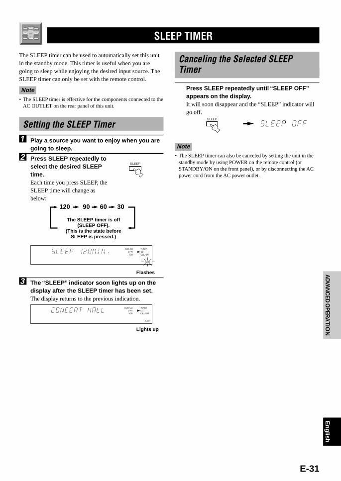
E-31
English
BA
SIC
OP
ER
ATIO
NADVAN
CED
OPER
AT
ION
AP
PE
ND
IXIN
TR
OD
UC
TIO
NP
RE
PAR
ATIO
N
The SLEEP timer can be used to automatically set this unitin the standby mode. This timer is useful when you aregoing to sleep while enjoying the desired input source. TheSLEEP timer can only be set with the remote control.
Note• The SLEEP timer is effective for the components connected to the
AC OUTLET on the rear panel of this unit.
Setting the SLEEP Timer
1 Play a source you want to enjoy when you aregoing to sleep.
2 Press SLEEP repeatedly toselect the desired SLEEPtime.Each time you press SLEEP, theSLEEP time will change asbelow:
3 The “SLEEP” indicator soon lights up on thedisplay after the SLEEP timer has been set.The display returns to the previous indication.
TEST
TIME/LEVEL SET MENU
EFFECT
DSP
DVD/LDD–TVVCR
TUNERCDCBL/SAT
SLEEP
120 90 60 30
The SLEEP timer is off(SLEEP OFF).
(This is the state beforeSLEEP is pressed.)
SLEEP TIMER
SLEEP
Flashes
Canceling the Selected SLEEPTimer
Press SLEEP repeatedly until “SLEEP OFF”appears on the display.It will soon disappear and the “SLEEP” indicator willgo off.
Note• The SLEEP timer can also be canceled by setting the unit in the
standby mode by using POWER on the remote control (orSTANDBY/ON on the front panel), or by disconnecting the ACpower cord from the AC power outlet.
DVD/LDD–TVVCR
TUNERCDCBL/SAT
SLEEP
Lights up
SLEEP
107.E800_25-31(Eng) 5/18/0, 1:38 PM31

E-32
APPENDIX
TROUBLESHOOTING
If the unit fails to operate normally, check the following points to determine whether the fault can be corrected by the simplemeasures suggested. If it cannot be corrected, or if the fault is not listed in the SYMPTOM column, disconnect the powercord and contact your authorized YAMAHA dealer or service center.
General
SYMPTOM
The unit fails to turn onwhen STANDBY/ON(POWER) is pressed, orenters in the standbymode soon after thepower has been turnedon.
The unit does not worknormally.
No sound and/or nopicture.
No picture.
The sound suddenlygoes off.
Only the speaker on oneside can be heard.
No sound from the effectspeakers.
CAUSE
The power cord is not connected or the plug isnot completely inserted.
The IMPEDANCE SELECTOR switch on therear panel is not fully set to the right or leftposition.
The internal microcomputer has been frozen byan external electric shock (lightning, excessivestatic electricity, etc.) or by a power supply withlow voltage.
Incorrect input or output cable connections.
An appropriate input source has not beenselected.
The speaker connections are not secure.
The sound is muted.
Digital signals other than PCM audio and thesignals encoded with Dolby Digital or DTSwhich this unit cannot reproduce are being inputto this unit by a CD-ROM, etc.
There is no S VIDEO connection between thisunit and the TV monitor, although S videosignals are being input to this unit.
The protection circuit has been activated becauseof a short circuit, etc.
The SLEEP timer has functioned.
Incorrect cable connections.
The sound effect is off.
A Dolby Surround, Dolby Digital or DTSdecoding DSP program is being used withmaterial not encoded with Dolby Surround,Dolby Digital or DTS.
The 96-kHz sampling 24-bit digital signals areinput to this unit.
REMEDY
Firmly connect the power cord.
Set the switch fully to the right or left positionwhen the unit is in the standby mode.
Set the unit in the standby mode and disconnectthe AC power cord from the AC power outlet.After about 30 seconds have passed, connect thepower and operate the unit again.
Connect the cables properly. If the problempersists, the cables may be defective.
Select an appropriate input source with INPUTSELECTOR or TAPE/MD MON / 6CH INPUT(or the input selector buttons).
Secure the connections.
Set VOLUME to the “m” position, pressMUTING to cancel a mute and adjust thevolume.
Play a source whose signals this unit canreproduce.
Connect the monitor’s “S” video input terminalto this unit’s S VIDEO MONITOR OUTterminal.
Set the unit in the standby mode and then turnon to reset the protection circuit.
Turn on the power, and play the source again.
Connect the cables properly. If the problempersists, the cables may be defective.
Press EFFECT to turn it on.
Select another DSP program.
Refer topage
13
13
—
9, 10
16
11
17
—
11
—
31
11
20
24
19
108.E800_32-37(Eng) 5/18/0, 1:38 PM32
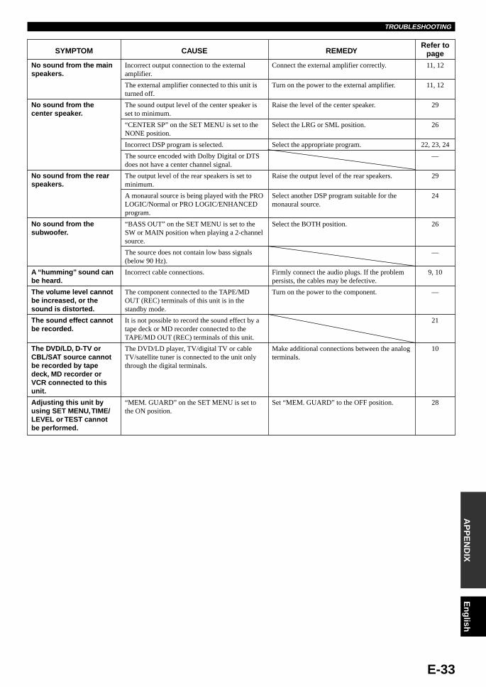
E-33
English
BA
SIC
OP
ER
ATIO
NADVAN
CED
OPER
AT
ION
AP
PE
ND
IXIN
TR
OD
UC
TIO
NP
RE
PAR
ATIO
NTROUBLESHOOTING
SYMPTOM
No sound from the mainspeakers.
No sound from thecenter speaker.
No sound from the rearspeakers.
No sound from thesubwoofer.
A “humming” sound canbe heard.
The volume level cannotbe increased, or thesound is distorted.
The sound effect cannotbe recorded.
The DVD/LD, D-TV orCBL/SAT source cannotbe recorded by tapedeck, MD recorder orVCR connected to thisunit.
Adjusting this unit byusing SET MENU, TIME/LEVEL or TEST cannotbe performed.
CAUSE
Incorrect output connection to the externalamplifier.
The external amplifier connected to this unit isturned off.
The sound output level of the center speaker isset to minimum.
“CENTER SP” on the SET MENU is set to theNONE position.
Incorrect DSP program is selected.
The source encoded with Dolby Digital or DTSdoes not have a center channel signal.
The output level of the rear speakers is set tominimum.
A monaural source is being played with the PROLOGIC/Normal or PRO LOGIC/ENHANCEDprogram.
“BASS OUT” on the SET MENU is set to theSW or MAIN position when playing a 2-channelsource.
The source does not contain low bass signals(below 90 Hz).
Incorrect cable connections.
The component connected to the TAPE/MDOUT (REC) terminals of this unit is in thestandby mode.
It is not possible to record the sound effect by atape deck or MD recorder connected to theTAPE/MD OUT (REC) terminals of this unit.
The DVD/LD player, TV/digital TV or cableTV/satellite tuner is connected to the unit onlythrough the digital terminals.
“MEM. GUARD” on the SET MENU is set tothe ON position.
REMEDY
Connect the external amplifier correctly.
Turn on the power to the external amplifier.
Raise the level of the center speaker.
Select the LRG or SML position.
Select the appropriate program.
Raise the output level of the rear speakers.
Select another DSP program suitable for themonaural source.
Select the BOTH position.
Firmly connect the audio plugs. If the problempersists, the cables may be defective.
Turn on the power to the component.
Make additional connections between the analogterminals.
Set “MEM. GUARD” to the OFF position.
Refer topage
11, 12
11, 12
29
26
22, 23, 24
—
29
24
26
—
9, 10
—
21
10
28
108.E800_32-37(Eng) 5/18/0, 1:38 PM33

E-34
When playing back a source encoded with DTS
SYMPTOM
A loud hissing noise isheard when playing backa source encoded withDTS.
A percussive noise isheard when playing backa source encoded withDTS.
No sound is heard whenplaying back a sourceencoded with DTS, evenif the input mode is setto AUTO on this unit.
No sound is heard whenplaying back an MD orDAT on which has beenrecorded a sourceencoded with DTS.
No sound is heard whenplaying back a source(CD, etc.) even if thecurrently selected inputmode is AUTO.
CAUSE
The player which plays back the source is notconnected to a digital audio signal input terminalof this unit.
The input mode is set to ANALOG on this unit.
If the input mode is set to AUTO, depending onsome sources, there may be a noise heard whilethis unit is identifying the format of the inputsignal.
The built-in DTS decoder does not functionbecause the player has a digital volume controland it is set at a position other than “maximum,”“neutral” or “ineffective.”
A source encoded with DTS cannot be recordedon an MD or DAT.
In the AUTO mode, the DTS-decoding modecannot be automatically changed to the normal(PCM) digital signal input mode.
REMEDY
The player must be connected to a digital audiosignal input terminal of this unit besides theanalog audio signal terminal connections.
Set a proper input mode to turn on the built-inDTS decoder.
Set the input mode of the currently selectedinput source to DTS.
Set the player’s digital volume control at themaximum, neutral or ineffective position.
Set the input mode to AUTO again.
Refer topage
10
18
18
—
—
19
Notes• It is necessary to use a DTS decoder to play back a source encoded with DTS, so the player which plays back the source must be connected
to a digital audio input terminal of this unit in the way described in this manual. If this connection is not made or only a D-to-A converter isbeing used without using a DTS decoder, only a loud hissing noise will be heard when you play back the source.
• The “t” indicator will flash when the input mode is set to AUTO and a search or skip operation is performed while playing back asource encoded with DTS. If this status continues for 30 or more seconds, the unit will automatically switch from DTS-decoding mode toPCM digital signal input mode and the “t” indicator will go out.
Remote control
SYMPTOM
The remote control doesnot work.
CAUSE
Direct sunlight or lighting (from an inverter typeof fluorescent lamp, etc.) is striking the remotecontrol sensor of this unit.
The batteries are weak.
REMEDY
Reposition the unit.
Replace all batteries with new ones.
Refer topage
3
2
OthersRefer to
page
—
—
REMEDY
Turn on the power of the unit.
Move the unit further away from suchequipment.
CAUSE
This unit is in the standby mode.
The unit is too close to the digital or high-frequency equipment.
SYMPTOM
The sound is degradedwhen listening withheadphones to a tapedeck or CD playerconnected to this unit.
There is noiseinterference from digitalor high-frequencyequipment, or the unit.
TROUBLESHOOTING
108.E800_32-37(Eng) 5/18/0, 1:38 PM34

E-35
English
BA
SIC
OP
ER
ATIO
NADVAN
CED
OPER
AT
ION
AP
PE
ND
IXIN
TR
OD
UC
TIO
NP
RE
PAR
ATIO
N
AUDIO SECTION• Minimum RMS Output Power
20 Hz to 20 kHz, 0.06% THD, 8 ohmsCenter, Rear L/R ......................................................................... 70 W1 kHz, 0.09% THD, 8 ohmsCenter, Rear L/R ......................................................................... 80 W
• Maximum Output Power (EIAJ)1 kHz, 10% THD, 8 ohms ........................................................ 105 W
• DIN Standard Output Power1 kHz, 0.7% THD, 4 ohmsCenter, Rear L/R ....................................................................... 110 W
• IEC Output Power1 kHz, 0.04% THD, 8 ohms ....................................................... 75 W
• Dynamic Power (IHF)8/6/4/2 ohms ........................................................ 90/110/135/160 W
• Damping Factor20 Hz to 20 kHz, 8 ohms ................................................................ 80
• Frequency ResponseCD etc. to MAIN L/R .............................. 10 Hz to 100 kHz, 0/–3 dB
• Total Harmonic Distortion (20 Hz to 20 kHz)6CH INPUT to REAR SP OUT, 35W/8 ohms ....................... 0.06 %
• Signal-to-Noise Ratio (IHF-A Network)CD etc. to MAIN PRE OUT (250 mV, Input Shorted) ........................................................ 103 dB
• Residual Noise (IHF-A Network)CENTER, REAR SP OUT ..................................................... 150 µV
• Input Sensitivity/ImpedanceCD etc. ................................................................. 150 mV/47 k-ohms6CH INPUT ......................................................... 150 mV/47 k-ohms
• Output Level/ImpedanceREC OUT ........................................................... 150 mV/1.2 k-ohmsPRE OUT ................................................................ 1.0 V/1.2 k-ohmsSUBWOOFER ........................................................ 4.0 V/1.2 k-ohms
• Channel Separation (Vol. –30 dB)CD etc. (Input 5.1 k-ohms terminated, 1 kHz/10 kHz)
..................................................................................... 60 dB/45 dB
VIDEO SECTION• Video Signal Type ........................................................... NTSC or PAL
• Video Signal Level ....................................................... 1 Vp-p/75 ohms
• Signal-to-Noise Ratio .................................................................. 50 dB
• Monitor Out Frequency Response .................... 5 Hz to 10 MHz, –3 dB
GENERAL• Power Supply ............................................................. AC 230 V, 50 Hz
• Power Consumption .................................................................... 180 W
• AC Outlet (100 W max. total) ..................................... 1 (SWITCHED)
• Dimensions (W x H x D) ...................................... 435 x 126 x 391 mm
• Weight ....................................................................................... 10.0 kg
• Accessories ................................................................... Remote control........................................................................................... Batteries
Specifications are subject to change without notice.
SPECIFICATIONS

YAMAHA ELECTRONICS CORPORATION, USA 6660 ORANGETHORPE AVE., BUENA PARK, CALIF. 90620, U.S.A.YAMAHA CANADA MUSIC LTD. 135 MILNER AVE., SCARBOROUGH, ONTARIO M1S 3R1, CANADAYAMAHA ELECTRONIK EUROPA G.m.b.H. SIEMENSSTR. 22-34, 25462 RELLINGEN BEI HAMBURG, F.R. OF GERMANYYAMAHA ELECTRONIQUE FRANCE S.A. RUE AMBROISE CROIZAT BP70 CROISSY-BEAUBOURG 77312 MARNE-LA-VALLEE CEDEX02, FRANCEYAMAHA ELECTRONICS (UK) LTD. YAMAHA HOUSE, 200 RICKMANSWORTH ROAD WATFORD, HERTS WD1 7JS, ENGLANDYAMAHA SCANDINAVIA A.B. J A WETTERGRENS GATA 1, BOX 30053, 400 43 VÄSTRA FRÖUNDA, SWEDENYAMAHA MUSIC AUSTRALIA PTY, LTD. 17-33 MARKET ST., SOUTH MELBOURNE, 3205 VIC., AUSTRALIA Printed in Malaysia V584180-1