DSP Development System - pudn.comread.pudn.com/downloads158/ebook/707037/10 DSP applications...
32
1 DSP Development System 1 • Testing the software and hardware tools with Code Composer Studio • Use of the TMS320C6711 DSK • Programming examples to test the tools Chapter 1 introduces several tools available for digital signal processing (DSP). These tools include the popular Code Composer Studio (CCS), which provides an integrated development environment (IDE); the DSP starter kit (DSK) with the TMS320C6711 floating-point processor onboard and complete support for input and output. Three examples are included to test both the software and hardware tools included with the DSK. 1.1 INTRODUCTION Digital signal processors such as the TMS320C6x (C6x) family of processors are like fast special-purpose microprocessors with a specialized type of architecture and instruction set appropriate for signal processing. The C6x notation is used to desig- nate a member of Texas Instruments’ (TI) TMS320C6000 family of digital signal processors. The architecture of the C6x digital signal processor is very well suited for numerically intensive calculations. Based on a very-long-instruction-word (VLIW) architecture, the C6x is considered to be TI’s most powerful processor. Digital signal processors are used for a wide range of applications, from com- munications and controls to speech and image processing. They are found in cellu- lar phones, fax/modems, disk drives, radio, and so on.These processors have become the product of choice for a number of consumer applications, since they have become very cost-effective. They can handle different tasks, since they can be DSP Applications Using C and the TMS320C6x DSK. Rulph Chassaing Copyright © 2002 John Wiley & Sons, Inc. ISBNs: 0-471-20754-3 (Hardback); 0-471-22112-0 (Electronic)
Transcript of DSP Development System - pudn.comread.pudn.com/downloads158/ebook/707037/10 DSP applications...

1DSP Development System
1
• Testing the software and hardware tools with Code Composer Studio• Use of the TMS320C6711 DSK• Programming examples to test the tools
Chapter 1 introduces several tools available for digital signal processing (DSP).These tools include the popular Code Composer Studio (CCS), which provides anintegrated development environment (IDE); the DSP starter kit (DSK) with theTMS320C6711 floating-point processor onboard and complete support for inputand output. Three examples are included to test both the software and hardwaretools included with the DSK.
1.1 INTRODUCTION
Digital signal processors such as the TMS320C6x (C6x) family of processors are likefast special-purpose microprocessors with a specialized type of architecture andinstruction set appropriate for signal processing. The C6x notation is used to desig-nate a member of Texas Instruments’ (TI) TMS320C6000 family of digital signalprocessors. The architecture of the C6x digital signal processor is very well suitedfor numerically intensive calculations. Based on a very-long-instruction-word(VLIW) architecture, the C6x is considered to be TI’s most powerful processor.
Digital signal processors are used for a wide range of applications, from com-munications and controls to speech and image processing. They are found in cellu-lar phones, fax/modems, disk drives, radio, and so on.These processors have becomethe product of choice for a number of consumer applications, since they havebecome very cost-effective. They can handle different tasks, since they can be
DSP Applications Using C and the TMS320C6x DSK. Rulph ChassaingCopyright © 2002 John Wiley & Sons, Inc.
ISBNs: 0-471-20754-3 (Hardback); 0-471-22112-0 (Electronic)

reprogrammed readily for a different application. DSP techniques have been verysuccessful because of the development of low-cost software and hardware support.For example, modems and speech recognition can be less expensive using DSP techniques.
DSP processors are concerned primarily with real-time signal processing. Real-time processing means that the processing must keep pace with some external event;whereas non-real-time processing has no such timing constraint. The external eventto keep pace with is usually the analog input. While analog-based systems with dis-crete electronic components such as resistors can be more sensitive to temperaturechanges, DSP-based systems are less affected by environmental conditions such astemperature. DSP processors enjoy the advantages of microprocessors. They areeasy to use, flexible, and economical.
A number of books and articles have been published that address the importanceof digital signal processors for a number of applications [1–20]. Various tech-nologies have been used for real-time processing, from fiber optics for very high fre-quency to DSP processors very suitable for the audio-frequency range. Commonapplications using these processors have been for frequencies from 0 to 20kHz.Speech can be sampled at 8kHz (how quickly samples are acquired), which impliesthat each value sampled is acquired at a rate of 1/(8kHz) or 0.125ms. A commonlyused sample rate of a compact disk is 44.1kHz. A/D-based boards in the megahertzsampling rate range are currently available.
The basic system consists of an analog-to-digital converter (ADC) to capture an input signal. The resulting digital representation of the captured signal is thenprocessed by a digital signal processor such as the C6x and then output through adigital-to-analog converter (DAC).Also included within the basic system is a specialinput filter for antialiasing to eliminate erroneous signals, and an output filter tosmooth or reconstruct the processed output signal.
1.2 DSK SUPPORT TOOLS
Most of the work presented in this book involves the design of a program to imple-ment a DSP application. To perform the experiments, the following tools are used:
1. TI’s DSP starter kit (DSK). The DSK package includes:
(a) Code Composer Studio (CCS), which provides the necessary softwaresupport tools. CCS provides an integrated development environment(IDE), bringing together the C compiler, assembler, linker, debugger, andso on.
(b) A board, shown in Figure 1.1a, that contains the TMS320C6711 (C6711)floating-point digital signal processor as well as a 16-bit codec for inputand output (I/O) support.
(c) A parallel cable (DB25) that connects the DSK board to a PC.
(d) A power supply for the DSK board.
2 DSP Development System

2. An IBM-compatible PC. The DSK board connects to the parallel port of thePC through the DB25 cable included with the DSK package.
3. An oscilloscope, signal generator, and speakers. A signal/spectrum analyzer isoptional. Shareware utilities are available that utilize the PC and a sound cardto create a virtual instrument such as an oscilloscope, a function generator, ora spectrum analyzer.
DSK Support Tools 3
(a)
(b)
FIGURE 1.1. TMS320C6711-based DSK board: (a) board; (b) diagram (Courtesy of TexasInstruments).

All the files/programs listed and discussed in this book (except the student projectfiles in Chapter 9) are included on the accompanying disk. Most of the examplescan also run on the fixed-point C6211-based DSK (which has been discontinued).A list of all the examples is given on pages xv–xviii.
1.2.1 DSK Board
The DSK package is powerful, yet relatively inexpensive ($295), with the necessaryhardware and software support tools for real-time signal processing [21–33]. It is acomplete DSP system. The DSK board, with an approximate dimension of 5 ¥ 8inches, includes the C6711 floating-point digital signal processor [22] and a 16-bitcodec AD535 for input and output.
The onboard codec AD535 [34] uses a sigma–delta technology that providesanalog-to-digital conversion (ADC) and digital-to-analog conversion (DAC). A 4-MHz clock onboard the DSK connects to this codec to provide a fixed samplingrate of 8kHz.
A daughter card expansion is also provided on the DSK board. We will illustrateinput and output by plugging an audio daughter card based on the PCM3003 stereocodec (not included with the DSK package) into an 80-pin connector on the DSKboard.The audio daughter card is available from Texas Instruments and is describedin Appendix F. The PCM3003 codec has variable sample rates up to 72kHz and canbe useful for applications requiring higher sampling rates and two accessible inputand output channels.
The DSK board includes 16MB (megabytes) of synchronous dynamic RAM(SDRAM) and 128kB (kilobytes) of flash ROM. Two connectors on the boardprovide input and output and are labeled IN (J7) and OUT (J6), respectively. Threeof the four user dip switches on the DSK board can be read from a program (aproject example on voice scrambling makes use of these switches). The onboardclock is 150MHz. Also onboard the DSK are voltage regulators that provide 1.8Vfor the C6711 core and 3.3V for its memory and peripherals.
1.2.2 TMS320C6711 Digital Signal Processor
The TMS320C6711 (C6711) is based on the very-long-instruction-word (VLIW)architecture, which is very well suited for numerically intensive algorithms. Theinternal program memory is structured so that a total of eight instructions can befetched every cycle. For example, with a clock rate of 150MHz, the C6711 is capableof fetching eight 32-bit instructions every 1/(150MHz) or 6.66ns.
Features of the C6711 include 72kB of internal memory, eight functional or exe-cution units composed of six ALUs and two multiplier units, a 32-bit address bus toaddress 4GB (gigabytes), and two sets of 32-bit general-purpose registers.
The C67xx (such as the C6701 and C6711) belong to the family of the C6x floating-point processors; whereas the C62xx and C64xx belong to the family of the C6x fixed-point processors. The C6711 is capable of both fixed- and floating-
4 DSP Development System

point processing. The architecture and instruction set of the C6711 are discussed inChapter 3.
1.3 CODE COMPOSER STUDIO
The Code Composer Studio (CCS) provides an integrated development environ-ment (IDE) to incorporate the software tools. CCS includes tools for code genera-tion, such as a C compiler, an assembler, and a linker. It has graphical capabilitiesand supports real-time debugging. It provides an easy-to-use software tool to buildand debug programs.
The C compiler compiles a C source program with extension .c to produce anassembly source file with extension.asm. The assembler assembles an.asm sourcefile to produce a machine language object file with extension.obj. The linker com-bines object files and object libraries as input to produce an executable file withextension.out. This executable file represents a linked common object file format(COFF), popular in Unix-based systems and adopted by several makers of digitalsignal processors [21]. This executable file can be loaded and run directly on theC6711 processor.
To create an application project, one can “add” the appropriate files to theproject. Compiler/linker options can readily be specified. A number of debuggingfeatures are available, including setting breakpoints and watching variables, viewingmemory, registers, and mixed C and assembly code, graphing results, and monitor-ing execution time. One can step through a program in different ways (step into, orover, or out).
Real-time analysis can be performed using real-time data exchange (RTDX)associated with DSP/BIOS (Appendix G). RTDX allows for data exchange betweenthe host and the target and analysis in real time without stopping the target. Keystatistics and performance can be monitored in real time. Through the Joint TeamAction Group (JTAG), communication with on-chip emulation support occurs tocontrol and monitor program execution. The C6711 DSK board includes a JTAGemulator interface.
1.3.1 CCS Installation and Support
Use the parallel (printer) cable DB25 to connect the DSK board (J2) to the paral-lel port on the PC, such as LPT1 or LPT2. Use the 5-V adapter included with theDSK package to connect to the power connector J4, to turn on the DSK. InstallCCS with the CD-ROM included with the DSK, preferably using the c:\tistructure (as default).
The CCS icon should be on the desktop as “CCS 2 [’C 6000]” and is used to launchCCS.The code generation tools (C compiler, assembler, linker) Version 4.1 are used.
On power, the three LEDs located near the four user dip switches should countfrom 1 to 7 (binary).
Code Composer Studio 5

CCS provides useful documentations included with the DSK package on the following (see the Help icon):
1. Code generation tools (compiler, assembler, linker, etc.)
2. Tutorials on CCS, compiler, RTDX, advanced DSP/BIOS
3. DSP instructions and registers
4. Tools on RTDX, DSP/BIOS, and so on.
An extensive amount of support material (pdf files) is included with CCS (seeRefs. 22 to 34). There are also a few examples included with CCS, such as a confi-dence test example for the DSK, an audio example, and an example associated withthe onboard flash.
CCS Version 2 was used to build and test the examples included in this book. Anumber of files included in the following subfolders/directories within c:\ti canbe very useful:
1. docs: contains documentation and manuals.
2. myprojects: supplied for your projects. All the programs and projects dis-cussed in this book can be placed within this subdirectory.
3. c6000\cgtools: contains code generation tools.
4. bin: contains many utilities.
5. c6000\examples: contains examples included with CCS.
6. c6000\RTDX: contains support files for real-time data transfer.
7. c6000\bios: contains support files for DSP/BIOS.
1.3.2 Useful Types of Files
You will be working with a number of files with different extensions. They include:
1. file.pjt: to create and build a project named file.
2. file.c: C source program.
3. file.asm: assembly source program created by the user, by the C compiler,or by the linear optimizer.
4. file.sa: linear assembly source program. The linear optimizer uses file.saas input to produce an assembly program file.asm.
5. file.h: header support file.
6. file.lib: library file, such as the run-time support library file rts6701.lib.
7. file.cmd: linker command file that maps sections to memory.
8. file.obj: object file created by the assembler.
6 DSP Development System

9. file.out: executable file created by the linker to be loaded and run on theprocessor.
1.4 PROGRAMMING EXAMPLES TO TEST THE DSK TOOLS
Three programming examples are introduced to illustrate some of the features ofCCS and the DSK board. The primary focus is to become familiar with both thesoftware and hardware tools. It is strongly suggested that you complete these threeexamples before proceeding to subsequent chapters.
1.4.1 Quick Test of DSK
Launch CCS from the icon on the desktop. Press GEL Æ Check DSK Æ QuickTest. The Quick Test can be used for confirmation of correct operation and instal-lation. The following message is then displayed:
Switches: 7
Revision: 2
Target is OK
This assumes that the first three switches, USER_SW1, USER_SW2, andUSER_SW3, are all in the up (ON) position. Change the switches to (1 1 0 x)2 so thatthe first two switches are up (press the third switch down). The fourth switch is notused.
Repeat the procedure to select GEL Æ Check DSK Æ Quick Test and verifythat the value of the switches is now 3 (with the display “Switches: 3”). You can setthe value of the first three user switches from 0 to 7. Within your program you canthen direct the execution of your code based on these eight values. Note that theQuick Test cycles the LEDs three times.
A confidence test program example is included with the DSK to test and verifyproper operation of the major components of the DSK, such as interrupts, LEDs,SDRAM, DMA, serial ports, and timers.
Alternative Quick Test of DSK
1. Open/launch CCS from the icon on the desktop. Select File Æ Load Program.Access the accompanying disk. Click on the folder sine8_intr to Open(load) the file sine8_intr.out. This loads the executable filesine8_intr.out into the C6711 processor.
2. Select Debug Æ Run. Connect the OUT (connector J6) on the DSK board toa speaker or to an oscilloscope and verify the generation of a 1-kHz tone. TheIN/OUT connectors (J7/J6) on the DSK board use a 3.5-mm jack audio cable.
Programming Examples to Test the DSK Tools 7

The folder sine8_intr contains the necessary files to implement Example 1.1,which introduces some features of the tools.
1.4.2 Support Files
Create a new folder within your PC hard drive and name it sine8_intr. It is rec-ommended that you place this folder in c:\ti\myprojects (it is assumed thatyou have installed CCS in c:\ti). Some of the same support files that are used inmany examples in this book are included on the accompanying disk in the folderSupport. For now, don’t worry too much about the content or functions of thesefiles. Additional support files are included in the CCS CD with the DSK package.Copy the following support files from the folder Support (on the accompanyingdisk) into the folder sine8_intr that you created in your hard drive:
1. C6xdsk.cmd: sample linker command file.
2. C6xdsk.h: header file that defines addresses of external memory interface,the serial ports, etc. (TI support file included with CCS).
3. C6xinterrupts.h: contains init functions for interrupt (TI support fileincluded with the DSK).
4. C6xdskinit.h: header file with the function prototypes.
5. C6xdskinit.c: contains several functions used for the examplecodec_poll included with CCS. It includes functions to initialize the DSK,the codec, the serial ports, and for input/output.
6. Vectors_11.asm: version of vectors.asm included with CCS, but modi-fied to handle interrupts. Twelve interrupts, INT4 through INT15, are avail-able, and INT11 is selected within this vector file.
Also copy the C source file sine8_intr.c and the GEL file amplitude.gel fromthe disk (sine8_intr folder) into the folder sine8_intr on your hard drive.
Note: If you are using a C6211 DSK (which has been discontinued), changeXINT0 to XINT1 within the function comm_intr in the file C6xdskinit.c. Thisis due to a silicon bug associated with the C6211.
1.4.3 Examples
Example 1.1: Sine Generation with Eight Points (sine8_intr)
This example generates a sinusoid using a table-lookup method. More important, itillustrates some features of CCS for editing, building a project, accessing the codegeneration tools, and running a program on the C6711 processor. The C sourceprogram sine8_intr.c shown in Figure 1.2 implements the sine generation.
8 DSP Development System
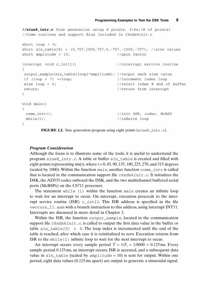
Program ConsiderationAlthough the focus is to illustrate some of the tools, it is useful to understand theprogram sine8_intr.c. A table or buffer sin_table is created and filled witheight points representing sin(t), where t = 0, 45, 90, 135, 180, 225, 270, and 315 degrees(scaled by 1000). Within the function main, another function comm_intr is calledthat is located in the communication support file c6xdskinit.c. It initializes theDSK, the AD535 codec onboard the DSK, and the two multichannel buffered serialports (McBSPs) on the C6711 processor.
The statement while (1) within the function main creates an infinite loop to wait for an interrupt to occur. On interrupt, execution proceeds to the inter-rupt service routine (ISR) c_int11. This ISR address is specified in the filevectors_11.asm with a branch instruction to this address, using interrupt INT11.Interrupts are discussed in more detail in Chapter 3.
Within the ISR, the function output_sample, located in the communicationsupport file C6xdskinit.c, is called to output the first data value in the buffer ortable sin_table[0] = 0. The loop index is incremented until the end of thetable is reached, after which case it is reinitialized to zero. Execution returns fromISR to the while(1) infinite loop to wait for the next interrupt to occur.
An interrupt occurs every sample period T = 1/Fs = 1/8000 = 0.125ms. Everysample period 0.125ms, an interrupt occurs, ISR is accessed, and a subsequent datavalue in sin_table (scaled by amplitude = 10) is sent for output. Within oneperiod, eight data values (0.125ms apart) are output to generate a sinusoidal signal.
Programming Examples to Test the DSK Tools 9
//sine8_intr.c Sine generation using 8 points, f=Fs/(# of points)
//Comm routines and support files included in C6xdskinit.c
short loop = 0;
short sin_table[8] = {0,707,1000,707,0,-707,-1000,-707}; //sine values
short amplitude = 10; //gain factor
interrupt void c_int11() //interrupt service routine
{
output_sample(sin_table[loop]*amplitude); //output each sine value
if (loop < 7) ++loop; //increment index loop
else loop = 0; //reinit index @ end of buffer
return; //return from interrupt
}
void main()
{
comm_intr(); //init DSK, codec, McBSP
while(1); //infinite loop
}
FIGURE 1.2. Sine generation program using eight points (sine8_intr.c).

The period of the output signal is T = 8(0.125ms) = 1ms, corresponding to a fre-quency of f = 1/T = 1kHz.
Create ProjectIn this section we illustrate how to create a project, adding the necessary files forbuilding the project sine8_intr. Access CCS (from the desktop).
1. To create the project file sine8_intr.pjt. Select Project Æ New. Typesine8_intr for project name as shown in Figure 1.3a. This project file issaved in sine8_intr (the folder you created in c:\ti\myprojects). The.pjt file stores project information on build options, source filenames, anddependencies.
2. To add files to project. Select Project Æ Add Files to Project. Look insine8_intr, Files of type C Source Files. Open the two C source filesC6xdskinit.c and sine8_intr.c. Open (to add to project) one file at atime; or place the cursor to one of these files, then to the other while holdingthe Shift key, and press Open. Click on the “+” symbol on the left of the ProjectFiles window within CCS to expand and verify that the two C source files havebeen added to the project.
3. Select Project Æ Add Files to Project. Look in sine8_intr. Use the pull-down menu for Files of type: and select ASM Source Files. Double-click onthe assembly source file vectors_11.asm to open/add it to the project.
4. Repeat step 3 but select Files of type: Linker Command File, and add thelinker command file C6xdsk.cmd to the project.
5. Repeat step 3, but select Files of type: Object and Library Files. Look inc:\ti\c6000\cgtools\lib and select the run-time support library filerts6701.lib (which supports the C67x/C62x architecture) to add to theproject. This assumes that you used the default destination of c:\ti whenyou installed CCS.
6. Verify that the linker command (.cmd) file, the project (.pjt) file, the library(.lib) file, the two C source (.c) files, and the assembly (.asm) file havebeen added to the project. The GEL file dsk6211_6711.gel is added auto-matically when you create the project. It initializes the DSK.
7. Note that there are no “include” files yet. Select Project Æ Scan All Depen-dencies. This adds/includes the header files: C6xdsk.h, C6xdskinit.h,C6xinterrupts.h, and C6x.h. The first three header files were copied(transferred) from the accompanying disk, and C6x.h is included with CCS.
The Files window in CCS should look as in Figure 1.3b. Any of the files (exceptthe library file) from CCS’s Files window can be displayed by clicking on it. Youshould not add header or include files to the project. They are added to the projectautomatically when you select: Scan All Dependencies.
10 DSP Development System

It is also possible to add files to a project simply by “dragging” the file (from adifferent window) and dropping it into the CCS Project window.
Code Generation and OptionsVarious options are associated with the code generation tools: C compiler and linkerto build a project.
Programming Examples to Test the DSK Tools 11
(a)
(b)
FIGURE 1.3. CCS Project View window for sine8_intr: (a) creating project; (b) pro-ject files.

Compiler Option. Select Project Æ Build Options. Figure 1.4a shows CCS windowBuild Options for the compiler. Select the following for the compiler option: (a)Basic (for Category), (b) Default (for Target Version), (c) Full Symbolic Debug (forGenerate Debug Info), (d) Speed most critical (for Opt Speed vs. size), (e) None(for Opt Level and Program Level Opt). The resulting compiler option is
–gks
The –k option is to keep the assembly source file sine8_intr.asm. The –g optionis to enable symbolic debugging information, useful during the debugging process,and used in conjunction with the option –s to interlist the C source file with theassembly source file sine8_intr.asm. generated. The –g option disables manycode optimizations to facilitate the debugging process.
Selecting “Default” for Target Version invokes a fixed-point implementation.(If you have a C6211 DSK, you must use this option.) The C6711-based DSK canuse either fixed- or floating-point processing. Most examples implemented in thisbook can run using fixed-point processing. You will need to select C671x to invokea floating-point implementation for the examples in Chapter 6 and 7.
If No Debug is selected (for Generate Debug Info), and –o3:File is selected(for Opt Level), the Compiler option is automatically changed to
–ks –o3
The –o3 option invokes the highest level of optimization for performance or exe-cution speed. For now, speed is not critical (neither is debugging). Use the compileroption –gks (you can type it directly in the compiler command window). Initially,one would not optimize for speed but to facilitate debugging. There are a numberof compiler options described in Ref. 26.
Linker Option. Click on Linker (from CCS Build Options) and select AbsoluteExecutable (for Output Module), sine8_intr.out (for Output Filename), andRun-time Autoinitialization (for Autoinit Model). The output filename defaults tothe name of the .pjt filename. The linker option should be displayed as in Figure1.4(b)
–g –c –o “sine8_intr.out” –x
The –c option is used to initialize variables at run time, and the –o option is toname the linked executable output file sine8_intr.out. Press OK.
Note that you can choose to store the executable file within a subfolder “Debug,”especially during the debugging stage of a project.
Again, these various options can be typed directly within the appropriatecommand windows.
12 DSP Development System

Programming Examples to Test the DSK Tools 13
(b)
FIGURE 1.4. CCS Build options: (a) compiler; (b) linker.
(a)
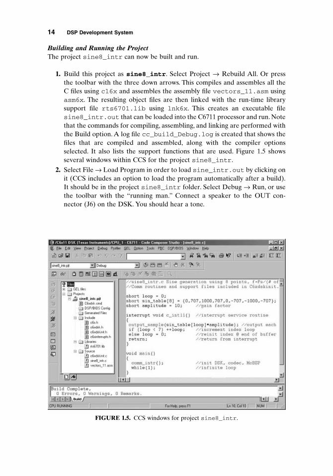
Building and Running the ProjectThe project sine8_intr can now be built and run.
1. Build this project as sine8_intr. Select Project Æ Rebuild All. Or press the toolbar with the three down arrows. This compiles and assembles all theC files using cl6x and assembles the assembly file vectors_11.asm usingasm6x. The resulting object files are then linked with the run-time librarysupport file rts6701.lib using lnk6x. This creates an executable filesine8_intr.out that can be loaded into the C6711 processor and run. Notethat the commands for compiling, assembling, and linking are performed withthe Build option. A log file cc_build_Debug.log is created that shows thefiles that are compiled and assembled, along with the compiler optionsselected. It also lists the support functions that are used. Figure 1.5 showsseveral windows within CCS for the project sine8_intr.
2. Select File Æ Load Program in order to load sine_intr.out by clicking onit (CCS includes an option to load the program automatically after a build).It should be in the project sine8_intr folder. Select Debug Æ Run, or usethe toolbar with the “running man.” Connect a speaker to the OUT con-nector (J6) on the DSK. You should hear a tone.
14 DSP Development System
FIGURE 1.5. CCS windows for project sine8_intr.

The sampling rate Fs of the codec is fixed at 8kHz. The frequency gener-ated is f = Fs/(number of points) = 8kHz/8 = 1kHz. Connect the output of theDSK to an oscilloscope to verify a 1-kHz sinusoidal signal with an amplitudeof approximately 0.85V p-p (peak to peak).
Monitoring the Watch WindowVerify that the processor is still running. Note the indicator “DSP RUNNING” atthe bottom left of CCS. The Watch window allows you to change the value of a parameter or to monitor a variable:
1. Select View Æ Quick Watch window, which should be displayed on the lower-section of CCS.Type amplitude, then click on “Add to Watch.”The amplitudevalue of 10 set in the program in Figure 1.2 should appear in the Watch window.
2. Change amplitude from 10 to 30.
3. Verify that the volume of the generated tone has increased (note that theprocessor was still running). The amplitude of the sine wave has increasedfrom approximately 0.85V p-p to approximately 2.6V p-p.
4. Change amplitude to 33 (as in step 2). Verify a higher-pitch tone, whichimplies that the frequency of the sine wave has changed just by changing itsamplitude. This is not so. You have overflowed the capacity of the 16-bit codecAD535. Since the values in the table are scaled by 33, the range of these valuesis now between + and -33,000. The range of output values is limited from -215
to (215 - 1), or from -32,768 to +32,767, due to the AD535 codec. Don’t attemptto send more than 16 bits’ worth of data to the codec. The onboard codec usesa 2’s-complement format.
Correcting Program Errors
1. Delete the semicolon in the statement
short amplitude = 10;
If the C source file sine8_intr is not displayed, double-click on it (from theFiles window).
2. Select Debug Æ Build to perform an incremental build or use the toolbar withthe two (not three) arrows. The incremental build is chosen so that only theC source file sine8_intr.c is compiled. With the Rebuild option (toolbarwith three arrows), files compiled and/or assembled previously would againgo through this unnecessary process.
3. An error message, highlighted in red, stating that a “;” is expected, shouldappear in the Build window of CCS (lower left). You may need to scroll-upthe Build window for a better display of this error message. Double-click onthe highlighted error message line. This should bring the cursor to the sectionof code where the error occurs. Make the appropriate correction, Build again,Load, and Run the program to verify your previous results.
Programming Examples to Test the DSK Tools 15

Applying the Slider Gel FileThe General Extension Language (GEL) is an interpretive language similar to (asubset of) C. It allows you to change a variable such as amplitude, sliding throughdifferent values while the processor is running. All variables must first be definedin your program.
1. Select File Æ Load GEL and open the file amplitude.gel, that you copied(from the accompanying disk) into the folder sine8_intr. Double-click onthe file amplitude.gel to view it within CCS. It should be displayed in theFiles window. This file is shown in Figure 1.6. By creating the slider functionamplitude shown in Figure 1.6, you can start with an initial value of 10 (firstvalue) for the variable amplitude that is set in the C program, up to a valueof 35 (second value), incremented by 5 (third value).
2. Select GEL Æ Sine Amplitude Æ Amplitude. This should bring out the Slider window shown in Figure 1.7, with the minimum value of 10 set foramplitude.
3. Press the up-arrow key to increase the amplitude value from 10 to 15, as dis-played in the Slider window. Verify that the volume of the sine wave gener-ated has increased. Press the up-arrow key again to continue increasing theslider, incrementing by 5 up to 30. The amplitude of the sine wave should beabout 2.6V p-p with an amplitude value set at 30. Now use the mouse to clickon the Slider window and slowly increase the slider position to 31, then 32,and verify that the frequency generated is still 1kHz. Increase the slider to 33and verify that you are no longer generating a 1-kHz sine wave (rather a signalwith two tones: 1 and 3kHz). The table values, scaled by amplitude, are nowbetween + and -33,000 (beyond the acceptable range by the codec).
Two sliders can readily be used, one to change the amplitude and the other tochange the frequency. A different frequency can be generated by changing the loopindex within the C program (e.g., stepping through every two points in the table;see Example 2.4). When you exit CCS after you build a project, all changes madeto the project can be saved. You can later return to the project with the status asyou left it before.
16 DSP Development System
/*Amplitude.gel Create slider and vary amplitude of sinewave*/
menuitem “Sine Amplitude”
slider Amplitude(10,35,5,1,amplitudeparameter) /*start at 10,up to 35*/
{
amplitude = amplitudeparameter; /*vary amplit of sine*/
}
FIGURE 1.6. GEL file to “slide” through different amplitude values in the sine generationprogram (amplitude.gel).

Example 1.2: Generation of Sinusoid and Plotting with CCS (sine8_buf)
This example generates a sinusoid with eight points, as in Example 1.1. More impor-tant, it illustrates CCS capabilities for plotting in both time and frequency domains.The program sine8_buf.c (Figure 1.8), implements this project. This programcreates a buffer to store the output data in memory.
Create this project as sine8_buf.pjt, add the necessary files to the project asin Example 1.1 (use sine8_buf.c in lieu of sine8_intr.c). Note that the necessary header support files are added to the project by selecting Project ÆScanning All Dependencies. All of the support files for this project are in the folder sine8_buf (on disk).
Build this project as sine8_buf. Load and run the executable filesine8_buf.out and verify that a 1-kHz sinusoid is generated with the output connected to a speaker or a scope (as in Example 1.1).
Plotting with CCSThe output buffer is being updated continuously every 256 points (you can readilychange the buffer size). Use CCS to plot the current output data stored in the bufferout_buffer.
1. Select View Æ Graph Æ Time/Frequency.
2. Change the Graph Property Dialog so that the options in Figure 1.9a areselected for a time-domain plot (use the pull-down menu when appropriate).The starting address of the output buffer is out_buffer. The other optionscan be left as default. Figure 1.10 shows a time-domain plot of the sinusoidalsignal.
Programming Examples to Test the DSK Tools 17
FIGURE 1.7. CCS slider window for varying the amplitude of a sine wave.

18 DSP Development System
//sine8_buf Sine generation. Output buffer plotted within CCS
//Comm routines and support files included in C6xdskinit.c
short loop = 0;
short sine_table[8] = {0,707,1000,707,0,-707,-1000,-707}; //sine values
short out_buffer[256]; //output buffer
const short BUFFERLENGTH = 256; //size of output buffer
short i = 0; //for buffer count
interrupt void c_int11() //interrupt service routine
{
output_sample(sine_table[loop]); //output each sine value
out_buffer[i] = sine_table[loop]; //output to buffer
i++; //increment buffer count
if (i == BUFFERLENGTH) i = 0; //if bottom reinit buffer count
if (loop < 7) ++loop; //increment index loop
else loop = 0; //if end of buffer,reinit index
return;
}
void main()
{
comm_intr(); //init DSK, codec, McBSP
while(1); //infinite loop
}
(a)
(b)
FIGURE 1.9. CCS Graph Property Dialog for sine8_buf: (a) for time-domain plot;(b) for frequency-domain plot.
FIGURE 1.8. Sine generation with output stored in memory also (sine8_buf.c).
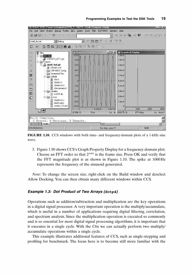
3. Figure 1.9b shows CCS’s Graph Property Display for a frequency-domain plot.Choose an FFT order so that 2order is the frame size. Press OK and verify thatthe FFT magnitude plot is as shown in Figure 1.10. The spike at 1000Hz represents the frequency of the sinusoid generated.
Note: To change the screen size, right-click on the Build window and deselectAllow Docking. You can then obtain many different windows within CCS.
Example 1.3: Dot Product of Two Arrays (dotp4)
Operations such as addition/subtraction and multiplication are the key operationsin a digital signal processor. A very important operation is the multiply/accumulate,which is useful in a number of applications requiring digital filtering, correlation,and spectrum analysis. Since the multiplication operation is executed so commonlyand is so essential for most digital signal processing algorithms, it is important thatit executes in a single cycle. With the C6x we can actually perform two multiply/accumulate operations within a single cycle.
This example illustrates additional features of CCS, such as single-stepping andprofiling for benchmark. The focus here is to become still more familiar with the
Programming Examples to Test the DSK Tools 19
1.3e+5
1.2e+5
1.0e+5
9.0e+4
7.7e+4
6.4e+4
5.1e+4
3.8e+4
2.6e+4
1.3e+4
00 1000 2000 3000
FIGURE 1.10. CCS windows with both time- and frequency-domain plots of a 1-kHz sinewave.

tools. We invoke the C compiler optimization to see how performance or executionspeed can be drastically increased.
The C source file dotp4.c (Figure 1.11) takes the sum of products of two arrays,each array with four numbers, contained in the header file dotp4.h (Figure 1.12).The first array contains the four numbers 1, 2, 3, and 4, and the second array con-tains the four numbers 0, 2, 4, and 6. The sum of products is (1 ¥ 0) + (2 ¥ 2) +(3 ¥ 4) + (4 ¥ 6) = 40.
The program can readily be modified to handle a larger set of data. No real-timeimplementation is used in this example, and no real-time I/O support files are
20 DSP Development System
//Dotp4.c Multiplies two arrays, each array with 4 numbers
int dotp(short *a, short *b, int ncount); //function prototype
#include <stdio.h> //for printf
#include “dotp4.h” //data file of numbers
#define count 4 //# of data in each array
short x[count] = {x_array}; //declara 1st array
short y[count] = {y_array}; //declara 2nd array
main()
{
int result = 0; //result sum of products
result = dotp(x,y,count); //call dotp function
printf(“result = %d (decimal) \n”, result); //print result
}
int dotp(short *a, short *b, int ncount) //dot product function
{
int sum = 0; //init sum
int i;
for (i = 0; i < ncount; i++)
sum += a[i] * b[i]; //sum of products
return(sum); //return sum as result
}
FIGURE 1.11. Sum-of-products program using C code (dotp4.c).
//dotp4.h Header file with two arrays of numbers
#define x_array 1,2,3,4
#define y_array 0,2,4,6
FIGURE 1.12. Header file with two arrays each with four numbers (dotp4.h).

needed. The support functions for interrupts are not needed here. The vector fileused in this example is less extensive, as shown in Figure 1.13.
Create and build this project as dotp4 and add the following files to the projectas in Example 1.1:
1. dotp4.c: C source file
2. vectors.asm: vector file defining entry address c_int00
3. C6xdsk.cmd: linker command file
4. rts6701.lib: library file
Do not add any “include” files using “Add Files to Project” since they are addedby selecting Project Æ Scan All Dependencies. The header file stdio.h is neededdue to the printf statement in the program dotp4.c to print the result.
Implementing a Variable Watch
1. Select Project Æ Options:
Compiler: –gs
Linker: –c –o dotp4.out
2. Rebuild All by selecting the toolbar with the three arrows (or select DebugÆ Build).
3. Select View Æ Quick Watch. Type sum to watch the variable sum, and clickon “Add to Watch.” A message “identifier not found” associated with sum isdisplayed (as Value) because this local variable “does not exist” yet since weare still in the function main.
4. Set a breakpoint at the line of code
sum += a[i] * b[i];
Programming Examples to Test the DSK Tools 21
*Vectors.asm Vector file for non-interrupt driven program
.title “vectors.asm”
.ref _c_int00 ;reference entry address
.sect “vectors” ;in vector section
rst: mvkl .s2 _c_int00,b0 ;lower 16 bits —> b0
mvkh .s2 _c_int00,b0 ;higher 16 bits —> b0
b .s2 b0 ;branch to entry address
nop ;5 NOPs for rest of fetch packet
nop
nop
nop
nop
FIGURE 1.13. Vector file for non-interrupt-driven program (vectors.asm).

by placing the mouse cursor (clicking) on that line, then right-click and select Toggle breakpoint. A circle on the left of that line of code should appear.
5. Select Debug Æ Run (or use the “running man” toolbar). The program exe-cutes up to the line of code with the set breakpoint. A yellow arrow will alsopoint to that line of code.
6. Single-step using F8 (or use the toolbar). Repeat or continue to single-stepand observe/watch the variable sum change in value to 0, 4, 16, 40. SelectDebug Æ Run, and verify that the resulting value of sum is printed as
sum = 40 (decimal)
7. Note the printf statement in the C program dotp4.c for printing the result. Such statement should be avoided, since it can take 3000 cycles toexecute.
Animating
1. Select Debug Æ Reset CPU Æ File Æ Reload Program to reload the exe-cutable file dotp4.out.
2. Again set the breakpoint as in the same line of code as before. Select DebugÆ Animate. Observe the variable sum change in values through the Watchwindow. The speed of animation can be controlled by selecting Option ÆCustomize Æ Animate Speed.
Benchmarking without Optimization (Profiling)In this section we illustrate how to benchmark a section of code: in this case, thedotp function. Verify that the same options for the compiler (–gs), and linker (–c –o dotp4.out) are still set.To profile code, you must use the compiler option–g for symbolic debugging information. Remove any breakpoint by clicking on theline of code with the breakpoint, right-click, and select Toggle breakpoint.
1. Select Debug Æ Reset CPU Æ File Æ Reload program, to reload the exe-cutable file.
2. Select Profiler Æ Start New Session, and enter dotp4 as the Profile SessionName. Then press OK.
3. Click on the icon to “Create Profile Area” which is the fourth icon from thetop left in Figure 1.14b. Figure 1.14b shows the added profile area for the func-tion dotp within the C source file dotp4.c.
4. Run the program. Verify the results shown in Figure 1.14b. This indicates thatit takes 138 cycles to execute the function dotp (with no optimization).
22 DSP Development System

FIGURE 1.14. CCS display of project dotp4 for profiling: (a) profile area of code lines 18–26;(b) profiling function dotp with no optimization; (c) profiling function dotp with optimization.
(a)
(b)
(c)
23

Benchmarking with Optimization (Profiling)In this section we illustrate how to optimize using one of the optimization options–o3.The program’s execution speed can be increased by the optimizing C compiler.Change the compiler option (select Project Æ Build Options) to
–g –o3
and use the same linker options as before (you can type this option directly). Theoption –o3 invokes the highest level of compiler optimization. Various compileroptions are described in Ref. 26. Rebuild All (toolbar with three arrows) and loadthe executable file (select File Æ Load Program) dotp4.out. Note that after theexecutable file is loaded, the entry address for execution is c_int00, as can be ver-ified by the disassembled file.
Select Debug Æ Run. Verify that it takes now 30 cycles (from 138) to execute the dotp function, as shown in Figure 1.14c. This is a considerable improvement using the C compiler optimizer. We further optimize the dot product example using an intrinsic function in Chapter 3 and code optimization techniques in Chapter 8.
1.5 SUPPORT PROGRAMS/FILES CONSIDERATIONS
The following support files are used for practically all the examples in this book:(1) C6xdskinit.c, (2) Vectors_11.asm, and (3) C6xdsk.cmd. For now, theemphasis associated with these files should be on using them.
1.5.1 Initialization/Communication File (C6xdskinit.c)
The function comm_intr within main in the C source program is located in the communication file c6xdskinit.c, a partial listing of which is shown in Figure 1.15. The DSK is initialized, then the transmit interrupt INT11 is configured andenabled.
Two functions for input and output are also included in this communicationsupport file. The function input_sample returns the input data value frommcbsp0_read,and the function output_sample calls mcbsp0_write for output.
Interrupt-Driven ProgramWith an interrupt-driven program, an interrupt is selected (we selected INT11). Thenonmaskable interrupt bit must be enabled as well as the Global Interrupt Enable(GIE) bit. The appropriate support functions for interrupts are within the supportfile C6xdskinterrupts.h and are called from the function comm_intr withinthe file C6xdskinit.c.
24 DSP Development System

//C6xdskinit.c Partial listing. Init DSK,AD535,McBSP
#include <c6x.h>#include “c6xdsk.h”#include “c6xdskinit.h”#include “c6xinterrupts.h”
void mcbsp0_write(int out_data) //function for writing{int temp;
if (polling) //bypass if interrupt-driven{temp = *(unsigned volatile int *)McBSP0_SPCR & 0x20000;while ( temp == 0)
temp = *(unsigned volatile int *)McBSP0_SPCR & 0x20000;}*(unsigned volatile int *)McBSP0_DXR = out_data;}
int mcbsp0_read() //function for reading{int temp;
if (polling) //bypass if interrupt-driven{temp = *(unsigned volatile int *)McBSP0_SPCR & 0x2;while ( temp == 0)
temp = *(unsigned volatile int *)McBSP0_SPCR & 0x2;}temp = *(unsigned volatile int *)McBSP0_DRR;return temp;}
void comm_poll() //communication with polling{
polling = 1; //setup for pollingc6x_dsk_init(); //call init DSK function
}
void comm_intr() //communication with interrupt{polling = 0; //if interrupt-drivenc6x_dsk_init(); //call init DSK functionconfig_Interrupt_Selector(11,XINT0); //using transmit interrupt INT11enableSpecificINT(11); //for specific interruptenableNMI(); //enable NMIenableGlobalINT(); //enable GIE global interruptmcbsp0_write(0); //write to SP0
}
void output_sample(int out_data) //added function for output{mcbsp0_write(out_data & 0xfffe); //mask out LSB
}
int input_sample() //added function for input{
return mcbsp0_read(); //read from McBSP0}
FIGURE 1.15. Partial listing of communication support program (C6xdskinit.c).
25

Polling-Based ProgramA polling-based program (non-interrupt driven) continuously polls or tests whetheror not data are ready to be received or transmitted.This scheme is less efficient thanthe interrupt scheme. Within the input read function mcbsp0_read, the content ofthe serial port control register (SPCR) is ANDed with 0x2 to test bit 1 (secondLSB) of the register, as shown in Figure B.8 (Appendix B). Within the output writefunction mcbsp0_write, SPCR is ANDed with 0x20000 to test bit 17. An inputdata value is accessed through the data receive register of the multichannel bufferedserial port (McBSP). An output data value is sent through the data transmit regis-ter of McBSP.
We use the polling scheme later in several examples to control the input andoutput data rate. Most examples are interrupt driven. Interrupts are discussed inChapter 3. For now, INT11 is generated via the serial port (McBSP).
1.5.2 Vector File (vectors_11.asm)
To select interrupt INT11, a branch instruction to the interrupt service routine (ISR)c_int11 located in the C program (sine8_intr.c or sine8_buf.c) is placedat the address INT11 in vectors_11.asm. A listing of the file vectors_11.asmis shown in Figure 1.16. Note the underscore preceding the name of the routine or function being called. The ISR is also referenced in vectors_11.asm using.ref _c_int11.
For a non-interrupt-driven vector program, modify vectors_11.asm:
1. Delete the reference to the interrupt service routine (ISR) .ref _c_int11.
2. For interrupt INT11, replace the branch instruction to the ISR by NOP.
1.5.3 Linker File (C6xdsk.cmd)
The linker command file C6xdsk.cmd is listed in Figure 1.17. It shows that sectionssuch as .text and .stack reside in IRAM, which is mapped to the internalmemory of the C6711 digital signal processor. It can be used as a generic samplelinker command file even though some portion of it is not necessary. In Chapter 4we show an example of the use of external RAM using SDRAM which starts at theaddress 0x80000000.
1.6 COMPILER/ASSEMBLER/LINKER SHELL
In previous examples the code generation tools for compiling, assembling, andlinking were invoked within CCS while building a project. The tools may also beinvoked directly outside CCS, using a DOS shell.
26 DSP Development System

*Vectors_11.asm Vector file for interrupt-driven program.ref _c_int11 ;ISR used in C program.ref _c_int00 ;entry address.sect “vectors” ;section for vectors
RESET_RST: mvkl .S2 _c_int00,B0 ;lower 16 bits —> B0Mvkh .S2 _c_int00,B0 ;upper 16 bits —> B0B .S2 B0 ;branch to entry addressNOP ;NOPs for remainder of FPNOP ;to fill 0x20 BytesNOPNOPNOP
NMI_RST: .loop 8NOP ;fill with 8 NOPs.endloop
RESV1: .loop 8NOP.endloop
RESV2: .loop 8NOP.endloop
INT4: .loop 8NOP.endloop
INT5: .loop 8NOP.endloop
INT6: .loop 8NOP.endloop
INT7: .loop 8NOP.endloop
INT8: .loop 8NOP.endloop
INT9: .loop 8NOP.endloop
INT10: .loop 8NOP.endloop
INT11: b _c_int11 ;branch to ISR.loop 7NOP.endloop
INT12: .loop 8NOP.endloop
INT13: .loop 8NOP.endloop
INT14: .loop 8NOP.endloop
INT15: .loop 8NOP.endloop
FIGURE 1.16. Interrupt-driven vector program (vectors_11.asm).
27

1.6.1 Compiler
The compiler shell can be invoked using
Cl6x [options] [files]
to compile and assemble files that can be C files with extension .c, assembly fileswith extension .asm, and linear assembly (introduced in Chapter 3) with extension.sa. A linear assembly program file is a “cross” between C and assembly that canprovide a compromise between the more versatile C program and the most efficientassembly program. For example,
Cl6x –gks –o3 file1.c, file2, file3.asm, file4.sa
invokes the C compiler to compile file1 and file2 (default to extension .c) andgenerates the assembly files file1.asm and file2.asm. This also invokes theassembler optimizer to optimize file4.sa and create file4.asm. Then the assem-bler (invoked with the shell command cl6x) assembles the four assembly sourcefiles and creates the four object files file1.obj, . . . , file4.obj. The option –gs
28 DSP Development System
/*C6xdsk.cmd Generic Linker command file*/
MEMORY
{
VECS: org = 0h, len = 0x220 /*vector section*/
IRAM: org = 0x00000220, len = 0x0000FDC0 /*internal memory*/
SDRAM: org = 0x80000000, len = 0x01000000 /*external memory*/
FLASH: org = 0x90000000, len = 0x00020000 /*flash memory*/
}
SECTIONS
{
vectors :> VECS
.text :> IRAM
.bss :> IRAM
.cinit :> IRAM
.stack :> IRAM
.sysmem :> SDRAM
.const :> IRAM
.switch :> IRAM
.far :> SDRAM
.cio :> SDRAM
}
FIGURE 1.17. Generic linker command file (C6xdsk.cmd).

adds debugger-specific information for debugging purposes and interlists C state-ments into assembly files, respectively. The –k option is to keep the assembly sourcefiles generated.
Four levels of compiler optimizations are available, with –o3 to invoke the highestlevel of optimization.Level 0 allocates variables to registers.Level 1 performs all level0 optimizations and eliminates local common expressions and removes unusedassignments. Level 2 performs all level 1 optimizations plus loop optimizations androlling (discussed later). Level 3 performs all level 2 optimizations and removes func-tions that are not called.There are also compiler optimizations to minimize code size(with possible degradation in execution speed).
Note that full optimization may change memory locations that can affect thefunctionality of a program. In such cases, these memory locations must be declaredas volatile. The compiler does not optimize volatile variables. A volatile variable isallocated to an uninitialized section in lieu of a register. Volatiles can be used whenmemory access is to be exactly as specified in the C code.
Initially, the functionality of a program is of primary importance. One should notinvoke any (or too-high-level) optimization option initially while debugging, sinceadditional debugger-specific information is provided to enhance the debuggingprocess. Such additional information suppresses the level of performance. It is alsodifficult to debug a program after optimization since the lines of code are usuallyno longer arranged in a serial fashion. Compiler options can also be set using theenvironment variable with C_OPTION.
1.6.2 Assembler
An assembly file file3.asm can also be assembled using
asm6x file3.asm
to create file3.obj. The .asm extension is optional. The resulting object files mustthen be linked with a run-time support library to create an executable commonobject file format (COFF) file with extension .out that can be loaded directly andrun on the digital signal processor.
1.6.3 Linker
The linker can be invoked using
lnk6x –c prog1.obj –o prog1.out –l rts6701.lib
The –c option tells the linker to use special conventions defined by the C environ-ment for automatic variable initialization at run time (another linker option, –cr,initializes the variables at load time). The –l option invokes the run-time support
Compiler/Assembler/Linker Shell 29

library file rts6701.lib. These options [–c (or –cr) and –l] must be used whenlinking. The object file prog1.obj is linked with the library file and creates theexecutable file prog1.out. Without the –o option, the executable file a.out (bydefault) is created.
The linker can also be invoked with the compiler shell command with the –zoption:
Cl6x –gks –o3 prog1.c prog2.asm –z –o prog.out –m prog.map–l rts6701.lib
to create the executable file prog.out. The –m option creates a map file that pro-vides a list of all the addresses of sections, symbols, and labels that can be useful fordebugging.
Linker options include –heap size to specify the heap size in bytes for dynamicmemory allocation (default is 1kB) and the option –stack size to specify the Csystem stack size in bytes. Other linker options can be found in Ref. 24.
The linker allocates your program in memory using a default location algorithm.It places the various sections into appropriate memory locations, where code anddata reside. By using a linker command file, with extension .cmd, one can customizethe allocation process, specifying MEMORY and SECTIONS directives within thecommand file.The linker directive MEMORY (uppercase) defines a memory modeland designates the origin and length of various available memory spaces. The direc-tive SECTIONS (uppercase) allocate the output sections into defined memory anddesignate the various code sections to available memory spaces.
The sample linker command file, shown in Figure 1.17, can be used for almost allof the examples in the book. We will use internal memory (IRAM) for code anddata. In Chapter 4 we illustrate implementation of a digital filter using externalmemory SDRAM, which starts at 0x80000000, with a length (size) of 0x1000000= 16MB. Flash starts at memory location 0x90000000 and has a length of0x20000 = 128kB.
The linker also links automatically boot.obj when using C programs to ini-tialize the run-time environment, setting the entry point to c_int00. The symbol_c_int00 is defined automatically when the linker option –c (or –cr) is invoked.The function _c_int00, included in the run-time support library, is the entry pointin boot.obj, which sets up the stack and calls main. The run-time library supportprogram boot.c is used to autoinitialize variables. The linker option –c invokesthe initialization process with boot.c. Note that it is defined in the vector filesvectors_11.asm and vectors.asm.
REFERENCES
Note: References 21 to 33 are included with the DSK package.
1. R. Chassaing, Digital Signal Processing Laboratory Experiments Using C and theTMS320C31 DSK, Wiley, New York, 1999.
30 DSP Development System

2. R. Chassaing, Digital Signal Processing with C and the TMS320C30, Wiley, New York,1992.
3. R. Chassaing and D. W. Horning, Digital Signal Processing with the TMS320C25, Wiley,New York, 1990.
4. N. Kehtarnavaz and M. Keramat, DSP System Design Using the TMS320C6000,Prentice Hall, Upper Saddle River, NJ, 2001.
5. N. Kehtarnavaz and B. Simsek, C6x-Based Digital Signal Processing, Prentice Hall,Upper Saddle River, NJ, 2000.
6. N. Dahnoun, DSP Implementation Using the TMS320C6x Processors, Prentice Hall,Upper Saddle River, NJ, 2000.
7. J. H. McClellan, R. W. Schafer, and M. A. Yoder, DSP First: A Multimedia Approach,Prentice Hall, Upper Saddle River, NJ, 1998.
8. C. Marven and G. Ewers, A Simple Approach to Digital Signal Processing, Wiley, NewYork, 1996.
9. J. Chen and H. V. Sorensen, A Digital Signal Processing Laboratory Using theTMS320C30, Prentice Hall, Upper Saddle River, NJ, 1997.
10. S. A. Tretter, Communication System Design Using DSP Algorithms, Plenum Press, NewYork, 1995.
11. A. Bateman and W. Yates, Digital Signal Processing Design, Computer Science Press,New York, 1991.
12. Y. Dote, Servo Motor and Motion Control Using Digital Signal Processors, Prentice Hall,Upper Saddle River, NJ, 1990.
13. J. Eyre, The newest breed trade off speed, energy consumption, and cost to vie for anever bigger piece of the action, IEEE Spectrum, June 2001.
14. J. M. Rabaey, ed., VLSI design and implementation fuels the signal-processing revolu-tion, IEEE Signal Processing, Jan. 1998.
15. P. Lapsley, J. Bier, A. Shoham, and E. Lee, DSP Processor Fundamentals: Architecturesand Features, Berkeley Design Technology, Berkeley, CA, 1996.
16. R. M. Piedra and A. Fritsh, Digital signal processing comes of age, IEEE Spectrum, May1996.
17. R. Chassaing, The need for a laboratory component in DSP education: a personalglimpse, Digital Signal Processing, Jan. 1993.
18. R. Chassaing,W.Anakwa, and A. Richardson, Real-time digital signal processing in edu-cation, Proceedings of the 1993 International Conference on Acoustics, Speech and SignalProcessing (ICASSP), Apr. 1993.
19. S. H. Leibson, DSP development software, EDN Magazine, Nov. 8, 1990.
20. D. W. Horning, An undergraduate digital signal processing laboratory, Proceedings ofthe 1987 ASEE Annual Conference, June 1987.
21. TMS320C6000 Programmer’s Guide, SPRU198D, Texas Instruments, Dallas, TX, 2000.
22. TMS320C6211 Fixed-Point Digital Signal Processor–TMS320C6711 Floating-PointDigital Signal Processor, SPRS073C, Texas Instruments, Dallas, TX, 2000.
References 31

23. TMS320C6000 CPU and Instruction Set Reference Guide, SPRU189F, Texas Instru-ments, Dallas, TX, 2000.
24. TMS320C6000 Assembly Language Tools User’s Guide, Texas Instruments, Dallas, TX,SPRU186G, 2000.
25. TMS320C6000 Peripherals Reference Guide, SPRU190D, Texas Instruments, Dallas, TX,2001.
26. TMS320C6000 Optimizing Compiler User’s Guide, SPRU187G, Texas Instruments,Dallas, TX, 2000.
27. TMS320C6000 Technical Brief, SPRU197D, Texas Instruments, Dallas, TX, 1999.
28. TMS320C64x Technical Overview, SPRU395, Texas Instruments, Dallas, TX, 2000.
29. TMS320C6x Peripheral Support Library Programmer’s Reference, SPRU273B, TexasInstruments, Dallas, TX, 1998.
30. Code Composer Studio User’s Guide, SPRU328B, Texas Instruments, Dallas, TX,2000.
31. Code Composer Studio Getting Started Guide, SPRU509, Texas Instruments, Dallas, TX,2001.
32. TMS320C6000 Code Composer Studio Tutorial, SPRU301C, Texas Instruments, Dallas,TX, 2000.
33. TLC320AD535C/I Data Manual Dual Channel Voice/Data Codec, SLAS202A, TexasInstruments, Dallas, TX, 1999.
34. B. W. Kernigan and D. M. Ritchie, The C Programming Language, Prentice Hall, UpperSaddle River, NJ, 1988.
35. Details on Signal Processing (quarterly publication), Texas Instruments, Dallas, TX.
36. G. R. Gircys, Understanding and Using COFF, O’Reilly & Associates, Newton, MA,1988.
32 DSP Development System