DSP & DSPpro Series C Programming Reference
256
DSP & DSPpro Series C Programming Reference Mar 2002 33 South La Patera Lane Santa Barbara, CA 93117 ph (805) 681-3300 fax (805) 681-3311 [email protected] For the following MEI motion controllers: CPCI Bus ISA Bus PC-104 Bus STD Bus DSPpro Series CPCI/DSP PCX/DSP 104/DSP SERCOS/STD DSPpro-Serial PCI Bus LC/DSP 104X/DSP STD/DSP DSPpro-VME PCI/DSP SERCOS/DSP SERCOS/104 VME Bus PC/DSP V6U/DSP
Transcript of DSP & DSPpro Series C Programming Reference

DSP & DSPpro SeriesC ProgrammingReference
Mar 2002
33 South La Patera LaneSanta Barbara, CA 93117ph (805) 681-3300fax (805) [email protected]
For the following MEI motion controllers:
CPCI Bus ISA Bus PC-104 Bus STD Bus DSPpro Series
CPCI/DSP PCX/DSP 104/DSP SERCOS/STD DSPpro-Serial
PCI Bus LC/DSP 104X/DSP STD/DSP DSPpro-VME
PCI/DSP SERCOS/DSP SERCOS/104 VME Bus
PC/DSP V6U/DSP

DSP & DSPpro Series C Programming Reference
Mar 2002Part # M001-0002 rev BCopyright 2002, Motion Engineering, Inc.
Motion Engineering, Inc.33 South La Patera LaneSanta Barbara, CA 93117-3214ph 805-681-3300fax 805-681-3311e-mail: [email protected]
This document contains proprietary and confidential information of Motion Engineering, Inc. and is protect-ed by Federal copyright law. The contents of the docu-ment may not be disclosed to third parties, translated, copied, or duplicated in any form, in whole or in part, without the express written permission of Motion En-gineering, Inc.
The information contained in this document is subject to change without notice. No part of this document may be reproduced or transmitted in any form or by any means, electronic or mechanical, for any purpose, without the express written permission of Motion En-gineering, Inc.
All product names shown are trademarks or registered trademarks of their respective owners.

CONTENTS
1 INTRODUCTIONThe Function Library . . . . . . . . . . . . . . . . . . . . . . . . . . . . . . . . . . . . . . . . . . . . . . . . . . . . . 1-1
Supported Languages & Operating Systems . . . . . . . . . . . . . . . . . . . . . . . . . . . . . 1-1Software Distribution . . . . . . . . . . . . . . . . . . . . . . . . . . . . . . . . . . . . . . . . . . . . . . . . . 1-1
To Load the Software . . . . . . . . . . . . . . . . . . . . . . . . . . . . . . . . . . . . . . . . . . . . . 1-2To Update Existing Software . . . . . . . . . . . . . . . . . . . . . . . . . . . . . . . . . . . . . . 1-2To Compile Your Program . . . . . . . . . . . . . . . . . . . . . . . . . . . . . . . . . . . . . . . . 1-2
Library Organization . . . . . . . . . . . . . . . . . . . . . . . . . . . . . . . . . . . . . . . . . . . . . . . . . . 1-2Compiled Library Naming Convention . . . . . . . . . . . . . . . . . . . . . . . . . . . . . 1-3Library/Firmware Version Control . . . . . . . . . . . . . . . . . . . . . . . . . . . . . . . . . 1-4
Library Compilation . . . . . . . . . . . . . . . . . . . . . . . . . . . . . . . . . . . . . . . . . . . . . . . . . . 1-5To Recompile the Function Library . . . . . . . . . . . . . . . . . . . . . . . . . . . . . . . . 1-5To Compile under Unsupported Operating Systems . . . . . . . . . . . . . . . . . . 1-5
Application Development Tips . . . . . . . . . . . . . . . . . . . . . . . . . . . . . . . . . . . . . . . . . . . . . 1-6Before Writing Any Code . . . . . . . . . . . . . . . . . . . . . . . . . . . . . . . . . . . . . . . . . . . . . 1-6Coding Recommendations . . . . . . . . . . . . . . . . . . . . . . . . . . . . . . . . . . . . . . . . . . . . . 1-6
Homing Routines Can Be Complicated . . . . . . . . . . . . . . . . . . . . . . . . . . . . . 1-6Use the Error Codes . . . . . . . . . . . . . . . . . . . . . . . . . . . . . . . . . . . . . . . . . . . . . . 1-7Look for Exception Events . . . . . . . . . . . . . . . . . . . . . . . . . . . . . . . . . . . . . . . . 1-7Save & Maintain Your Firmware . . . . . . . . . . . . . . . . . . . . . . . . . . . . . . . . . . . 1-7CONFIG.EXE Utility . . . . . . . . . . . . . . . . . . . . . . . . . . . . . . . . . . . . . . . . . . . . . 1-8
Troubleshooting Tips . . . . . . . . . . . . . . . . . . . . . . . . . . . . . . . . . . . . . . . . . . . . . . . . . 1-9Motion Developer’s Support Program . . . . . . . . . . . . . . . . . . . . . . . . . . . . . . . . . . . . . . 1-10
To Get Software Updates . . . . . . . . . . . . . . . . . . . . . . . . . . . . . . . . . . . . . . . . . . . . . 1-10Future Controller Purchases . . . . . . . . . . . . . . . . . . . . . . . . . . . . . . . . . . . . . . . . . . 1-10VERSION.EXE Utility . . . . . . . . . . . . . . . . . . . . . . . . . . . . . . . . . . . . . . . . . . . . . . 1-11Firmware Versions . . . . . . . . . . . . . . . . . . . . . . . . . . . . . . . . . . . . . . . . . . . . . . . . . . . . 1-11
2 CONFIGURATION FUNCTIONSQuick List . . . . . . . . . . . . . . . . . . . . . . . . . . . . . . . . . . . . . . . . . . . . . . . . . . . . . . . . . . . . . . . 2-2
Configuration Functions . . . . . . . . . . . . . . . . . . . . . . . . . . . . . . . . . . . . . . . . . . . . . . 2-2SERCOS Functions . . . . . . . . . . . . . . . . . . . . . . . . . . . . . . . . . . . . . . . . . . . . . . . . . . . 2-5typedefs and #defines . . . . . . . . . . . . . . . . . . . . . . . . . . . . . . . . . . . . . . . . . . . . . . . . . 2-6Error #defines . . . . . . . . . . . . . . . . . . . . . . . . . . . . . . . . . . . . . . . . . . . . . . . . . . . . . . . . 2-9More #defines . . . . . . . . . . . . . . . . . . . . . . . . . . . . . . . . . . . . . . . . . . . . . . . . . . . . . . 2-11
Firmware . . . . . . . . . . . . . . . . . . . . . . . . . . . . . . . . . . . . . . . . . . . . . . . . . . . . . . . . . . . . . . 2-13Sample Rate . . . . . . . . . . . . . . . . . . . . . . . . . . . . . . . . . . . . . . . . . . . . . . . . . . . . . . . . . . . . 2-14Boot Memory . . . . . . . . . . . . . . . . . . . . . . . . . . . . . . . . . . . . . . . . . . . . . . . . . . . . . . . . . . . 2-15Closed Loop Configuration . . . . . . . . . . . . . . . . . . . . . . . . . . . . . . . . . . . . . . . . . . . . . . . 2-17Feedback Configuration . . . . . . . . . . . . . . . . . . . . . . . . . . . . . . . . . . . . . . . . . . . . . . . . . . 2-18Dual Loop Configuration . . . . . . . . . . . . . . . . . . . . . . . . . . . . . . . . . . . . . . . . . . . . . . . . . 2-20Encoder Integrity Checking . . . . . . . . . . . . . . . . . . . . . . . . . . . . . . . . . . . . . . . . . . . . . . . 2-22Step Output Configuration . . . . . . . . . . . . . . . . . . . . . . . . . . . . . . . . . . . . . . . . . . . . . . . . 2-24Step Output Speed Range . . . . . . . . . . . . . . . . . . . . . . . . . . . . . . . . . . . . . . . . . . . . . . . . 2-26Analog Output Voltage Configuration . . . . . . . . . . . . . . . . . . . . . . . . . . . . . . . . . . . . . . 2-28PID Filter Parameters . . . . . . . . . . . . . . . . . . . . . . . . . . . . . . . . . . . . . . . . . . . . . . . . . . . . 2-29Auxiliary Filter Parameters . . . . . . . . . . . . . . . . . . . . . . . . . . . . . . . . . . . . . . . . . . . . . . . 2-31Home Action Configuration . . . . . . . . . . . . . . . . . . . . . . . . . . . . . . . . . . . . . . . . . . . . . . 2-32Home Logic Configuration . . . . . . . . . . . . . . . . . . . . . . . . . . . . . . . . . . . . . . . . . . . . . . . 2-34Limit Input Action Configuration . . . . . . . . . . . . . . . . . . . . . . . . . . . . . . . . . . . . . . . . . 2-37Limit Input Level Configuration . . . . . . . . . . . . . . . . . . . . . . . . . . . . . . . . . . . . . . . . . . 2-39
i

CONTENTS
ii
Amp Fault Input Configuration . . . . . . . . . . . . . . . . . . . . . . . . . . . . . . . . . . . . . . . . . . . .2-41Amp Enable Output Configuration . . . . . . . . . . . . . . . . . . . . . . . . . . . . . . . . . . . . . . . . .2-43Software Position Limits . . . . . . . . . . . . . . . . . . . . . . . . . . . . . . . . . . . . . . . . . . . . . . . . .2-45In Position . . . . . . . . . . . . . . . . . . . . . . . . . . . . . . . . . . . . . . . . . . . . . . . . . . . . . . . . . . . . . .2-47Error Limit . . . . . . . . . . . . . . . . . . . . . . . . . . . . . . . . . . . . . . . . . . . . . . . . . . . . . . . . . . . . . .2-48Interrupt Configuration . . . . . . . . . . . . . . . . . . . . . . . . . . . . . . . . . . . . . . . . . . . . . . . . . . .2-50SERCOS Initialization . . . . . . . . . . . . . . . . . . . . . . . . . . . . . . . . . . . . . . . . . . . . . . . . . . .2-53SERCOS Phase 2 & 3 IDNs Configuration . . . . . . . . . . . . . . . . . . . . . . . . . . . . . . . . . .2-56SERCOS Cyclic Data Configuration . . . . . . . . . . . . . . . . . . . . . . . . . . . . . . . . . . . . . . .2-58SERCOS Drive Addresses . . . . . . . . . . . . . . . . . . . . . . . . . . . . . . . . . . . . . . . . . . . . . . . .2-60SERCOS Change Operation Mode . . . . . . . . . . . . . . . . . . . . . . . . . . . . . . . . . . . . . . . . .2-61SERCOS Read/Write IDN . . . . . . . . . . . . . . . . . . . . . . . . . . . . . . . . . . . . . . . . . . . . . . . .2-62SERCOS Read/Write Multiple IDNs . . . . . . . . . . . . . . . . . . . . . . . . . . . . . . . . . . . . . . .2-64SERCOS Procedures . . . . . . . . . . . . . . . . . . . . . . . . . . . . . . . . . . . . . . . . . . . . . . . . . . . . .2-66SERCOS Read/Write Cyclic Data . . . . . . . . . . . . . . . . . . . . . . . . . . . . . . . . . . . . . . . . .2-68SERCOS Enable/Disable LED . . . . . . . . . . . . . . . . . . . . . . . . . . . . . . . . . . . . . . . . . . . .2-70SERCOS Drive Status/Reset . . . . . . . . . . . . . . . . . . . . . . . . . . . . . . . . . . . . . . . . . . . . . .2-71SERCOS Diagnostics . . . . . . . . . . . . . . . . . . . . . . . . . . . . . . . . . . . . . . . . . . . . . . . . . . . .2-73
3 OPERATION FUNCTIONSQuick List . . . . . . . . . . . . . . . . . . . . . . . . . . . . . . . . . . . . . . . . . . . . . . . . . . . . . . . . . . . . . . .3-2Initialization . . . . . . . . . . . . . . . . . . . . . . . . . . . . . . . . . . . . . . . . . . . . . . . . . . . . . . . . . . . . .3-8Initialization with Environment Variables . . . . . . . . . . . . . . . . . . . . . . . . . . . . . . . . . . . .3-9PCI and CompactPCI Initialization . . . . . . . . . . . . . . . . . . . . . . . . . . . . . . . . . . . . . . . . .3-10PCI and CompactPCI Board Identification . . . . . . . . . . . . . . . . . . . . . . . . . . . . . . . . . .3-11Error Handling . . . . . . . . . . . . . . . . . . . . . . . . . . . . . . . . . . . . . . . . . . . . . . . . . . . . . . . . . .3-13Single Axis Point-to-Point Motion . . . . . . . . . . . . . . . . . . . . . . . . . . . . . . . . . . . . . . . . .3-17Single-Axis S-Curve Profile Motion . . . . . . . . . . . . . . . . . . . . . . . . . . . . . . . . . . . . . . .3-19Single-Axis Parabolic Profile Motion . . . . . . . . . . . . . . . . . . . . . . . . . . . . . . . . . . . . . .3-21Multi-Axis Point-to-Point Motion . . . . . . . . . . . . . . . . . . . . . . . . . . . . . . . . . . . . . . . . . .3-22Velocity Move . . . . . . . . . . . . . . . . . . . . . . . . . . . . . . . . . . . . . . . . . . . . . . . . . . . . . . . . . .3-23Coordinated Axis Map . . . . . . . . . . . . . . . . . . . . . . . . . . . . . . . . . . . . . . . . . . . . . . . . . . .3-24Start/End Coordinated Point List . . . . . . . . . . . . . . . . . . . . . . . . . . . . . . . . . . . . . . . . . .3-25Coordinated Motion Parameters . . . . . . . . . . . . . . . . . . . . . . . . . . . . . . . . . . . . . . . . . . .3-26Start/Stop Coordinated Motion . . . . . . . . . . . . . . . . . . . . . . . . . . . . . . . . . . . . . . . . . . . .3-28Linear Coordinated Motion . . . . . . . . . . . . . . . . . . . . . . . . . . . . . . . . . . . . . . . . . . . . . . .3-29Circular Coordinated Motion . . . . . . . . . . . . . . . . . . . . . . . . . . . . . . . . . . . . . . . . . . . . . .3-30User I/O During Coordinated Motion . . . . . . . . . . . . . . . . . . . . . . . . . . . . . . . . . . . . . .3-31Cubic Spline Coordinated Motion . . . . . . . . . . . . . . . . . . . . . . . . . . . . . . . . . . . . . . . . .3-33Frame Buffer Management . . . . . . . . . . . . . . . . . . . . . . . . . . . . . . . . . . . . . . . . . . . . . . .3-36Position Control . . . . . . . . . . . . . . . . . . . . . . . . . . . . . . . . . . . . . . . . . . . . . . . . . . . . . . . . .3-38Trajectory Control . . . . . . . . . . . . . . . . . . . . . . . . . . . . . . . . . . . . . . . . . . . . . . . . . . . . . . .3-40Motion Status . . . . . . . . . . . . . . . . . . . . . . . . . . . . . . . . . . . . . . . . . . . . . . . . . . . . . . . . . . .3-42Axis Status . . . . . . . . . . . . . . . . . . . . . . . . . . . . . . . . . . . . . . . . . . . . . . . . . . . . . . . . . . . . . .3-44Axis State . . . . . . . . . . . . . . . . . . . . . . . . . . . . . . . . . . . . . . . . . . . . . . . . . . . . . . . . . . . . . .3-45Axis Source . . . . . . . . . . . . . . . . . . . . . . . . . . . . . . . . . . . . . . . . . . . . . . . . . . . . . . . . . . . . .3-46Stop Event . . . . . . . . . . . . . . . . . . . . . . . . . . . . . . . . . . . . . . . . . . . . . . . . . . . . . . . . . . . . . .3-48Emergency Stop Event . . . . . . . . . . . . . . . . . . . . . . . . . . . . . . . . . . . . . . . . . . . . . . . . . . .3-50Abort Event . . . . . . . . . . . . . . . . . . . . . . . . . . . . . . . . . . . . . . . . . . . . . . . . . . . . . . . . . . . . .3-52Event Recovery . . . . . . . . . . . . . . . . . . . . . . . . . . . . . . . . . . . . . . . . . . . . . . . . . . . . . . . . .3-54Dedicated Inputs . . . . . . . . . . . . . . . . . . . . . . . . . . . . . . . . . . . . . . . . . . . . . . . . . . . . . . . . .3-56
CONTENTS
iii
User I/O Port Control . . . . . . . . . . . . . . . . . . . . . . . . . . . . . . . . . . . . . . . . . . . . . . . . . . . . 3-58User I/O Bit Control . . . . . . . . . . . . . . . . . . . . . . . . . . . . . . . . . . . . . . . . . . . . . . . . . . . . . 3-61User I/O Monitoring . . . . . . . . . . . . . . . . . . . . . . . . . . . . . . . . . . . . . . . . . . . . . . . . . . . . . 3-63Analog Inputs . . . . . . . . . . . . . . . . . . . . . . . . . . . . . . . . . . . . . . . . . . . . . . . . . . . . . . . . . . . 3-65Axis Analog Inputs . . . . . . . . . . . . . . . . . . . . . . . . . . . . . . . . . . . . . . . . . . . . . . . . . . . . . . 3-67Axis Analog Outputs . . . . . . . . . . . . . . . . . . . . . . . . . . . . . . . . . . . . . . . . . . . . . . . . . . . . 3-69Counter/Timer . . . . . . . . . . . . . . . . . . . . . . . . . . . . . . . . . . . . . . . . . . . . . . . . . . . . . . . . . . 3-71Master/Slave . . . . . . . . . . . . . . . . . . . . . . . . . . . . . . . . . . . . . . . . . . . . . . . . . . . . . . . . . . . . 3-73Master/Cam . . . . . . . . . . . . . . . . . . . . . . . . . . . . . . . . . . . . . . . . . . . . . . . . . . . . . . . . . . . . 3-75Feed Speed Override . . . . . . . . . . . . . . . . . . . . . . . . . . . . . . . . . . . . . . . . . . . . . . . . . . . . . 3-77Position Latching . . . . . . . . . . . . . . . . . . . . . . . . . . . . . . . . . . . . . . . . . . . . . . . . . . . . . . . . 3-79On-Board Jogging . . . . . . . . . . . . . . . . . . . . . . . . . . . . . . . . . . . . . . . . . . . . . . . . . . . . . . . 3-81Multiple Controllers . . . . . . . . . . . . . . . . . . . . . . . . . . . . . . . . . . . . . . . . . . . . . . . . . . . . . 3-83Trajectory Frames . . . . . . . . . . . . . . . . . . . . . . . . . . . . . . . . . . . . . . . . . . . . . . . . . . . . . . . 3-85I/O Frames . . . . . . . . . . . . . . . . . . . . . . . . . . . . . . . . . . . . . . . . . . . . . . . . . . . . . . . . . . . . . 3-87Position-Triggered Frames . . . . . . . . . . . . . . . . . . . . . . . . . . . . . . . . . . . . . . . . . . . . . . . 3-88Looping Sequence Frames . . . . . . . . . . . . . . . . . . . . . . . . . . . . . . . . . . . . . . . . . . . . . . . . 3-90Action Frames . . . . . . . . . . . . . . . . . . . . . . . . . . . . . . . . . . . . . . . . . . . . . . . . . . . . . . . . . . 3-92Filter Frames . . . . . . . . . . . . . . . . . . . . . . . . . . . . . . . . . . . . . . . . . . . . . . . . . . . . . . . . . . . 3-94Frame Control . . . . . . . . . . . . . . . . . . . . . . . . . . . . . . . . . . . . . . . . . . . . . . . . . . . . . . . . . . 3-95Time . . . . . . . . . . . . . . . . . . . . . . . . . . . . . . . . . . . . . . . . . . . . . . . . . . . . . . . . . . . . . . 3-97Direct Memory Access . . . . . . . . . . . . . . . . . . . . . . . . . . . . . . . . . . . . . . . . . . . . . . . . . . . 3-98
A ABOUT THE DSP CONTROLLERHardware Architecture . . . . . . . . . . . . . . . . . . . . . . . . . . . . . . . . . . . . . . . . . . . . . . . . . . . .A-2
Hardware + Firmware + Software . . . . . . . . . . . . . . . . . . . . . . . . . . . . . . . . . . . . . .A-3Internal Boot Sequence . . . . . . . . . . . . . . . . . . . . . . . . . . . . . . . . . . . . . . . . . . . . . . .A-4Firmware Execution . . . . . . . . . . . . . . . . . . . . . . . . . . . . . . . . . . . . . . . . . . . . . . . . . .A-4Step Motor Control via VFCs . . . . . . . . . . . . . . . . . . . . . . . . . . . . . . . . . . . . . . . . . .A-6
Motion Concepts . . . . . . . . . . . . . . . . . . . . . . . . . . . . . . . . . . . . . . . . . . . . . . . . . . . . . . . . .A-8What is a Frame? . . . . . . . . . . . . . . . . . . . . . . . . . . . . . . . . . . . . . . . . . . . . . . . . . . . . .A-8Communication via 3 Words in I/O Space . . . . . . . . . . . . . . . . . . . . . . . . . . . . . . .A-8Function Execution Time . . . . . . . . . . . . . . . . . . . . . . . . . . . . . . . . . . . . . . . . . . . . . .A-8Coordinated Motion . . . . . . . . . . . . . . . . . . . . . . . . . . . . . . . . . . . . . . . . . . . . . . . . . .A-9How to Program Coordinated Motion . . . . . . . . . . . . . . . . . . . . . . . . . . . . . . . . . .A-10I/O with Coordinated Motion . . . . . . . . . . . . . . . . . . . . . . . . . . . . . . . . . . . . . . . . .A-11
B ABOUT SERCOSBrief Intro . . . . . . . . . . . . . . . . . . . . . . . . . . . . . . . . . . . . . . . . . . . . . . . . . . . . . . . . . . . . . . .B-2
About the MEI SERCOS Controller . . . . . . . . . . . . . . . . . . . . . . . . . . . . . . . . . . . .B-2Supported Drives/Modules . . . . . . . . . . . . . . . . . . . . . . . . . . . . . . . . . . . . . . . . . . . .B-2
MEI Software . . . . . . . . . . . . . . . . . . . . . . . . . . . . . . . . . . . . . . . . . . . . . . . . . . . . . . . . . . . .B-3Initialization Structures . . . . . . . . . . . . . . . . . . . . . . . . . . . . . . . . . . . . . . . . . . . . . . .B-3Drive Manufacturers . . . . . . . . . . . . . . . . . . . . . . . . . . . . . . . . . . . . . . . . . . . . . . . . . .B-3Drive Modes . . . . . . . . . . . . . . . . . . . . . . . . . . . . . . . . . . . . . . . . . . . . . . . . . . . . . . . . .B-4Initialization Status . . . . . . . . . . . . . . . . . . . . . . . . . . . . . . . . . . . . . . . . . . . . . . . . . . .B-4
MEI Developer Topics . . . . . . . . . . . . . . . . . . . . . . . . . . . . . . . . . . . . . . . . . . . . . . . . . . . .B-6Service Channel Error Messages . . . . . . . . . . . . . . . . . . . . . . . . . . . . . . . . . . . . . . .B-6
SERCOS Overview . . . . . . . . . . . . . . . . . . . . . . . . . . . . . . . . . . . . . . . . . . . . . . . . . . . . . . .B-7Operation Modes . . . . . . . . . . . . . . . . . . . . . . . . . . . . . . . . . . . . . . . . . . . . . . . . . . . . .B-8Closed-Loop Tuning . . . . . . . . . . . . . . . . . . . . . . . . . . . . . . . . . . . . . . . . . . . . . . . . . .B-8
CONTENTS
iv
Axis/Drive Assignments . . . . . . . . . . . . . . . . . . . . . . . . . . . . . . . . . . . . . . . . . . . . . . B-9Data Transmission . . . . . . . . . . . . . . . . . . . . . . . . . . . . . . . . . . . . . . . . . . . . . . . . . . . B-9
Telegrams . . . . . . . . . . . . . . . . . . . . . . . . . . . . . . . . . . . . . . . . . . . . . . . . . . . . . . . . . . . . . B-11BOF Delimiter . . . . . . . . . . . . . . . . . . . . . . . . . . . . . . . . . . . . . . . . . . . . . . . . . . . . . B-11ADR Target Address . . . . . . . . . . . . . . . . . . . . . . . . . . . . . . . . . . . . . . . . . . . . . . . . B-12Message Field . . . . . . . . . . . . . . . . . . . . . . . . . . . . . . . . . . . . . . . . . . . . . . . . . . . . . . B-12FCS (Frame Check Sequence) . . . . . . . . . . . . . . . . . . . . . . . . . . . . . . . . . . . . . . . . B-12EOF (End Of Frame) Delimiter . . . . . . . . . . . . . . . . . . . . . . . . . . . . . . . . . . . . . . . B-13Data Record . . . . . . . . . . . . . . . . . . . . . . . . . . . . . . . . . . . . . . . . . . . . . . . . . . . . . . . . B-13Master Synchronization Telegram . . . . . . . . . . . . . . . . . . . . . . . . . . . . . . . . . . . . B-14Master Data Telegram . . . . . . . . . . . . . . . . . . . . . . . . . . . . . . . . . . . . . . . . . . . . . . . B-15Amplifier Telegram . . . . . . . . . . . . . . . . . . . . . . . . . . . . . . . . . . . . . . . . . . . . . . . . . B-17
SERCOS Data Types . . . . . . . . . . . . . . . . . . . . . . . . . . . . . . . . . . . . . . . . . . . . . . . . . . . . B-19Data Block Structure . . . . . . . . . . . . . . . . . . . . . . . . . . . . . . . . . . . . . . . . . . . . . . . . B-19Data Block Structure of IDNs . . . . . . . . . . . . . . . . . . . . . . . . . . . . . . . . . . . . . . . . B-19Element 1: IDNumbers . . . . . . . . . . . . . . . . . . . . . . . . . . . . . . . . . . . . . . . . . . . . . B-20Element 2: Name of Operation Data . . . . . . . . . . . . . . . . . . . . . . . . . . . . . . . . . . B-21Element 3: Attributes of Operation Data . . . . . . . . . . . . . . . . . . . . . . . . . . . . . . B-21Element 4: Operation Data Unit . . . . . . . . . . . . . . . . . . . . . . . . . . . . . . . . . . . . . . B-22Element 5: Minimum Input Value of Operation Data . . . . . . . . . . . . . . . . . . . B-23Element 6: Maximum Input Value of Operation Data . . . . . . . . . . . . . . . . . . . B-23Element 7: Operation Data . . . . . . . . . . . . . . . . . . . . . . . . . . . . . . . . . . . . . . . . . . B-23Procedures . . . . . . . . . . . . . . . . . . . . . . . . . . . . . . . . . . . . . . . . . . . . . . . . . . . . . . . . . B-24
SERCOS Communications . . . . . . . . . . . . . . . . . . . . . . . . . . . . . . . . . . . . . . . . . . . . . . . B-25Synchronization . . . . . . . . . . . . . . . . . . . . . . . . . . . . . . . . . . . . . . . . . . . . . . . . . . . . B-25Ring Timing . . . . . . . . . . . . . . . . . . . . . . . . . . . . . . . . . . . . . . . . . . . . . . . . . . . . . . . B-25SERCOS Initialization . . . . . . . . . . . . . . . . . . . . . . . . . . . . . . . . . . . . . . . . . . . . . . B-27

FIGURES
v
1 INTRODUCTION
Figure 1-1 Naming Convention for Compiled Libraries . . . . . . . . . . . . . . . . . . . 1-3
2 CONFIGURATION FUNCTIONS
Figure 2-1 Dual-Loop Control: PCI/DSP . . . . . . . . . . . . . . . . . . . . . . . . . . . . . 2-21Figure 2-2 Motion Status During Trapezoidal Profile Move . . . . . . . . . . . . . . . 2-35Figure 2-3 DSP Interrupt Circuits . . . . . . . . . . . . . . . . . . . . . . . . . . . . . . . . . . . 2-50Figure 2-4 DSP’s Internal Memory Registers . . . . . . . . . . . . . . . . . . . . . . . . . . 2-51
3 OPERATION FUNCTIONS
Figure 3-1 Trapezoidal Profile Motion . . . . . . . . . . . . . . . . . . . . . . . . . . . . . . . 3-18Figure 3-2 S-Curve Profile Motion . . . . . . . . . . . . . . . . . . . . . . . . . . . . . . . . . . 3-19Figure 3-3 Parabolic Profile Motion . . . . . . . . . . . . . . . . . . . . . . . . . . . . . . . . . 3-21Figure 3-4 End Point Handling . . . . . . . . . . . . . . . . . . . . . . . . . . . . . . . . . . . . . 3-33Figure 3-5 Motion Status During Trapezoidal Profile Move . . . . . . . . . . . . . . . 3-43Figure 3-6 Undedicated Counter/Timer . . . . . . . . . . . . . . . . . . . . . . . . . . . . . . . 3-72
A ABOUT THE DSP CONTROLLERFigure A-1 DSP Controller Block Diagram . . . . . . . . . . . . . . . . . . . . . . . . . . . . .A-3Figure A-2 The DSP’s Main Execution Loop . . . . . . . . . . . . . . . . . . . . . . . . . . . .A-4Figure A-3 Formula for PID Algorithm . . . . . . . . . . . . . . . . . . . . . . . . . . . . . . . .A-6Figure A-4 2-Axis Coordinated Motion . . . . . . . . . . . . . . . . . . . . . . . . . . . . . . . .A-9Figure A-5 Simple Coordinated Move . . . . . . . . . . . . . . . . . . . . . . . . . . . . . . . .A-11
B ABOUT SERCOSFigure B-1 SERCOS Topology . . . . . . . . . . . . . . . . . . . . . . . . . . . . . . . . . . . . . . .B-7Figure B-2 SERCOS Cycles - Telegrams - Data Records . . . . . . . . . . . . . . . . .B-10Figure B-3 General Telegram Structure . . . . . . . . . . . . . . . . . . . . . . . . . . . . . . .B-11Figure B-4 Telegram Communications . . . . . . . . . . . . . . . . . . . . . . . . . . . . . . . .B-11Figure B-5 BOF Delimiter . . . . . . . . . . . . . . . . . . . . . . . . . . . . . . . . . . . . . . . . .B-11Figure B-6 ADR Target Address . . . . . . . . . . . . . . . . . . . . . . . . . . . . . . . . . . . .B-12Figure B-7 FCS (Frame Check Sequence) . . . . . . . . . . . . . . . . . . . . . . . . . . . . .B-12Figure B-8 EOF Delimiter . . . . . . . . . . . . . . . . . . . . . . . . . . . . . . . . . . . . . . . . .B-13Figure B-9 Data record Structure . . . . . . . . . . . . . . . . . . . . . . . . . . . . . . . . . . . .B-13Figure B-10 MST Telegram Structure . . . . . . . . . . . . . . . . . . . . . . . . . . . . . . . . .B-14Figure B-11 MDT Telegram Structure . . . . . . . . . . . . . . . . . . . . . . . . . . . . . . . . .B-15Figure B-12 AT Telegram Structure . . . . . . . . . . . . . . . . . . . . . . . . . . . . . . . . . . .B-17Figure B-13 Data Block Structure of IDNs . . . . . . . . . . . . . . . . . . . . . . . . . . . . .B-19Figure B-14 IDNumber Structure . . . . . . . . . . . . . . . . . . . . . . . . . . . . . . . . . . . . .B-20Figure B-15 Operation Data Name Structure . . . . . . . . . . . . . . . . . . . . . . . . . . . .B-21Figure B-16 Operation Data Attribute Structure . . . . . . . . . . . . . . . . . . . . . . . . . .B-21Figure B-17 Operation Data Unit Structure . . . . . . . . . . . . . . . . . . . . . . . . . . . . .B-23Figure B-18 Operation Data Variable Length Structure . . . . . . . . . . . . . . . . . . . .B-23Figure B-19 Procedure Element 7: Bit Definitions . . . . . . . . . . . . . . . . . . . . . . .B-24Figure B-20 SERCOS Ring Timing . . . . . . . . . . . . . . . . . . . . . . . . . . . . . . . . . . .B-26Figure B-21 Phase 0 Operations . . . . . . . . . . . . . . . . . . . . . . . . . . . . . . . . . . . . . .B-27Figure B-22 Phase 1 Operations . . . . . . . . . . . . . . . . . . . . . . . . . . . . . . . . . . . . . .B-28Figure B-23 Phase 2 Operations . . . . . . . . . . . . . . . . . . . . . . . . . . . . . . . . . . . . . .B-28Figure B-24 Phase 3 Operations . . . . . . . . . . . . . . . . . . . . . . . . . . . . . . . . . . . . . .B-29Figure B-25 Phase 4 Operations . . . . . . . . . . . . . . . . . . . . . . . . . . . . . . . . . . . . . .B-31

FIGURES
vi
TABLES
1 INTRODUCTION Table 1-1 Library Source Files in sources Directory . . . . . . . . . . . . . . . . . . . . . . . . . 1-3 Table 1-2 Library Product, Compiler and Versions . . . . . . . . . . . . . . . . . . . . . . . . . . 1-3 Table 1-3 Library Memory Models . . . . . . . . . . . . . . . . . . . . . . . . . . . . . . . . . . . . . . 1-4 Table 1-4 Library Extensions . . . . . . . . . . . . . . . . . . . . . . . . . . . . . . . . . . . . . . . . . . . 1-4 Table 1-5 Library Product, Compiler and Versions . . . . . . . . . . . . . . . . . . . . . . . . . . 1-4 Table 1-6 Library Typedefs . . . . . . . . . . . . . . . . . . . . . . . . . . . . . . . . . . . . . . . . . . . . 1-5 Table 1-7 CONFIG.EXE Command Options . . . . . . . . . . . . . . . . . . . . . . . . . . . . . . . 1-8 Table 1-8 Contacting MEI Technical Support . . . . . . . . . . . . . . . . . . . . . . . . . . . . . 1-10
2 CONFIGURATION FUNCTIONS Table 2-1 True & False Values . . . . . . . . . . . . . . . . . . . . . . . . . . . . . . . . . . . . . . . . . . 2-6 Table 2-2 High & Low Values . . . . . . . . . . . . . . . . . . . . . . . . . . . . . . . . . . . . . . . . . . 2-6 Table 2-3 DSP Configuration’ . . . . . . . . . . . . . . . . . . . . . . . . . . . . . . . . . . . . . . . . . . 2-6 Table 2-4 DSP Software Version . . . . . . . . . . . . . . . . . . . . . . . . . . . . . . . . . . . . . . . . 2-6 Table 2-5 I/O Port . . . . . . . . . . . . . . . . . . . . . . . . . . . . . . . . . . . . . . . . . . . . . . . . . . . . 2-6 Table 2-6 Events . . . . . . . . . . . . . . . . . . . . . . . . . . . . . . . . . . . . . . . . . . . . . . . . . . . . . 2-7 Table 2-7 Axis Status . . . . . . . . . . . . . . . . . . . . . . . . . . . . . . . . . . . . . . . . . . . . . . . . . 2-7 Table 2-8 Axis Source . . . . . . . . . . . . . . . . . . . . . . . . . . . . . . . . . . . . . . . . . . . . . . . . . 2-7 Table 2-9 PID Filter Parameters . . . . . . . . . . . . . . . . . . . . . . . . . . . . . . . . . . . . . . . . . 2-8 Table 2-10 Aux Filter Parameters . . . . . . . . . . . . . . . . . . . . . . . . . . . . . . . . . . . . . . . . . 2-8 Table 2-11 Error #defines . . . . . . . . . . . . . . . . . . . . . . . . . . . . . . . . . . . . . . . . . . . . . . . 2-9 Table 2-12 Master Slave Control . . . . . . . . . . . . . . . . . . . . . . . . . . . . . . . . . . . . . . . . 2-11 Table 2-13 Integration Modes . . . . . . . . . . . . . . . . . . . . . . . . . . . . . . . . . . . . . . . . . . . 2-11 Table 2-14 Feedback Devices . . . . . . . . . . . . . . . . . . . . . . . . . . . . . . . . . . . . . . . . . . . 2-11 Table 2-15 Home/Index Configurations . . . . . . . . . . . . . . . . . . . . . . . . . . . . . . . . . . . 2-11 Table 2-16 Step Output Pulse Speeds . . . . . . . . . . . . . . . . . . . . . . . . . . . . . . . . . . . . . 2-12 Table 2-17 Step Mode Types . . . . . . . . . . . . . . . . . . . . . . . . . . . . . . . . . . . . . . . . . . . 2-12 Table 2-18 Trigger Sense . . . . . . . . . . . . . . . . . . . . . . . . . . . . . . . . . . . . . . . . . . . . . . 2-12 Table 2-19 Firmware Version & Option Numbers . . . . . . . . . . . . . . . . . . . . . . . . . . . 2-13 Table 1-20 Max Sample Rate . . . . . . . . . . . . . . . . . . . . . . . . . . . . . . . . . . . . . . . . . . . 2-14 Table 2-21 Possible Feedback Devices . . . . . . . . . . . . . . . . . . . . . . . . . . . . . . . . . . . . 2-18 Table 2-22 Step Pulse Output . . . . . . . . . . . . . . . . . . . . . . . . . . . . . . . . . . . . . . . . . . . 2-26 Table 2-23 Step Speed Ranges . . . . . . . . . . . . . . . . . . . . . . . . . . . . . . . . . . . . . . . . . . 2-26 Table 2-24 PID Filter Parameters . . . . . . . . . . . . . . . . . . . . . . . . . . . . . . . . . . . . . . . . 2-29 Table 2-25 Integration Active/Not Active . . . . . . . . . . . . . . . . . . . . . . . . . . . . . . . . . 2-29 Table 2-26 First Auxiliary Coefficient . . . . . . . . . . . . . . . . . . . . . . . . . . . . . . . . . . . . 2-31 Table 2-27 Derivative Sample Rate . . . . . . . . . . . . . . . . . . . . . . . . . . . . . . . . . . . . . . 2-31 Table 2-28 Possible Homing Actions . . . . . . . . . . . . . . . . . . . . . . . . . . . . . . . . . . . . . 2-32 Table 2-29 Home Index Configurations . . . . . . . . . . . . . . . . . . . . . . . . . . . . . . . . . . . 2-34 Table 2-30 Possible Home Logic Configurations . . . . . . . . . . . . . . . . . . . . . . . . . . . . 2-35 Table 2-31 Possible DSP-Generated Actions . . . . . . . . . . . . . . . . . . . . . . . . . . . . . . . 2-37 Table 2-32 Possible Axis Actions . . . . . . . . . . . . . . . . . . . . . . . . . . . . . . . . . . . . . . . . 2-41 Table 2-33 Possible Axis Actions . . . . . . . . . . . . . . . . . . . . . . . . . . . . . . . . . . . . . . . . 2-45 Table 2-34 Possible Axis Actions . . . . . . . . . . . . . . . . . . . . . . . . . . . . . . . . . . . . . . . . 2-48 Table 2-35 SERCOS Phases . . . . . . . . . . . . . . . . . . . . . . . . . . . . . . . . . . . . . . . . . . . . 2-53 Table 2-36 Baud Rates . . . . . . . . . . . . . . . . . . . . . . . . . . . . . . . . . . . . . . . . . . . . . . . . 2-53 Table 2-37 SERCOS Drive Modes . . . . . . . . . . . . . . . . . . . . . . . . . . . . . . . . . . . . . . . 2-54 Table 2-38 Mapping of Drive Status Word to Dedicated I/O Registers . . . . . . . . . . . 2-54 Table 2-39 SERCOS Manufacturer defines . . . . . . . . . . . . . . . . . . . . . . . . . . . . . . . . 2-55 Table 2-40 SERCOS Baud Rates . . . . . . . . . . . . . . . . . . . . . . . . . . . . . . . . . . . . . . . . 2-60 Table 2-41 SERCOS Operating Modes . . . . . . . . . . . . . . . . . . . . . . . . . . . . . . . . . . . 2-61 Table 2-42 SERCOS Drive Status Word . . . . . . . . . . . . . . . . . . . . . . . . . . . . . . . . . . 2-71 Table 2-43 Drive Status Word Mapping to DSP Dedicated I/O Register . . . . . . . . . 2-71 Table 2-44 Class 1 Diagnostic Word . . . . . . . . . . . . . . . . . . . . . . . . . . . . . . . . . . . . . 2-73 Table 2-45 Class 2 Diagnostic Word . . . . . . . . . . . . . . . . . . . . . . . . . . . . . . . . . . . . . 2-73
vii

TABLES
viii
3 OPERATION FUNCTIONS Table 3-1 Error Codes . . . . . . . . . . . . . . . . . . . . . . . . . . . . . . . . . . . . . . . . . . . . . . . .3-13 Table 3-2 Return Values for in_sequence, in_motion, frames_left . . . . . . . . . . . . .3-42 Table 3-3 axis__status Conditions for an Axis . . . . . . . . . . . . . . . . . . . . . . . . . . . .3-44 Table 3-4 axis_state Conditions for an Axis . . . . . . . . . . . . . . . . . . . . . . . . . . . . . .3-45 Table 3-5 Possible Sources of Exception Events (Returned by axis_source) . . . . . .3-46 Table 3-6 User I/O Connector (Any board)
PC/PCX, STD, V6U, 104X & CPCI DSP Series 3-59 Table 3-7 User I/O Connector (Boards with 4 axes or less)
PC/PCX, STD, V6U, 104X & CPCI DSP Series 3-59 Table 3-8 User I/O Connector:
104 & LC DSP Series (100 pins) 3-59 Table 3-9 Conversion of Base Units for User I/O Port . . . . . . . . . . . . . . . . . . . . . . .3-60 Table 3-10 Analog Input Connections . . . . . . . . . . . . . . . . . . . . . . . . . . . . . . . . . . . . .3-66 Table 3-11 Master/Slave Parameters . . . . . . . . . . . . . . . . . . . . . . . . . . . . . . . . . . . . . .3-73 Table 3-12 How the DSP Updates the Trajectory . . . . . . . . . . . . . . . . . . . . . . . . . . . .3-86 Table 3-13 Selecting a Trigger for dsp_position_trigger . . . . . . . . . . . . . . . . . . . . . . .3-88 Table 3-14 Possible Frame Actions . . . . . . . . . . . . . . . . . . . . . . . . . . . . . . . . . . . . . . .3-88 Table 3-15 Possible Frame Actions- Looping Sequence Frames . . . . . . . . . . . . . . . .3-90 Table 3-16 Possible Frame Actions in Action Frames . . . . . . . . . . . . . . . . . . . . . . . .3-92 Table 3-17 PID Filter Parameter Mapping . . . . . . . . . . . . . . . . . . . . . . . . . . . . . . . . .3-94 Table 3-18 Frame Control Words . . . . . . . . . . . . . . . . . . . . . . . . . . . . . . . . . . . . . . . .3-95 Table 3-19 Encoder DMA Addresses . . . . . . . . . . . . . . . . . . . . . . . . . . . . . . . . . . . . .3-98 Table 3-20 Dedicated I/O DMA Addresses . . . . . . . . . . . . . . . . . . . . . . . . . . . . . . . . .3-98 Table 3-21 User I/O DMA Addresses . . . . . . . . . . . . . . . . . . . . . . . . . . . . . . . . . . . . .3-98 Table 3-22 Internal Logic DMA Addresses . . . . . . . . . . . . . . . . . . . . . . . . . . . . . . . .3-99
A ABOUT THE DSP CONTROLLER Table A-1 DSP Boot Sequence . . . . . . . . . . . . . . . . . . . . . . . . . . . . . . . . . . . . . . . . . . A-4 Table A-2 Trajectory Calculations at Sample n . . . . . . . . . . . . . . . . . . . . . . . . . . . . . A-5 Table A-3 PID Terms . . . . . . . . . . . . . . . . . . . . . . . . . . . . . . . . . . . . . . . . . . . . . . . . . A-6 Table A-4 Step Pulse Output Speed Ranges . . . . . . . . . . . . . . . . . . . . . . . . . . . . . . . . A-7 Table A-5 Minimum Hardware Revision Levels Required for Faster Step Output Speed A-7 Table A-6 How Functions Communicate with the DSP . . . . . . . . . . . . . . . . . . . . . . . A-8 Table A-7 How Many Points Can Be Stored in DSP Buffer? . . . . . . . . . . . . . . . . . A-10
B ABOUT SERCOS Table B-1 Supported Drives and I/O Modules . . . . . . . . . . . . . . . . . . . . . . . . . . . . . . B-2 Table B-2 SERCOS Drive Modes Supported . . . . . . . . . . . . . . . . . . . . . . . . . . . . . . B-4 Table B-3 Service Channel Error Messages . . . . . . . . . . . . . . . . . . . . . . . . . . . . . . . . B-6 Table B-4 SERCOS Has 3 Main Operation Modes . . . . . . . . . . . . . . . . . . . . . . . . . . B-8 Table B-5 Address Values vs. Phases During Telegram Transmission . . . . . . . . . . B-12 Table B-6 MST Telegram Fields . . . . . . . . . . . . . . . . . . . . . . . . . . . . . . . . . . . . . . . B-14 Table B-7 MDT Telegram Fields . . . . . . . . . . . . . . . . . . . . . . . . . . . . . . . . . . . . . . . B-16 Table B-8 MDT Telegram Control Word (Same as S-0-134) . . . . . . . . . . . . . . . . . B-16 Table B-9 AT Telegram Fields . . . . . . . . . . . . . . . . . . . . . . . . . . . . . . . . . . . . . . . . . B-17 Table B-10 AT Telegram Status Word (Same as S-0-135) . . . . . . . . . . . . . . . . . . . . B-18 Table B-11 The 7 Elements of an IDN . . . . . . . . . . . . . . . . . . . . . . . . . . . . . . . . . . . . B-20 Table B-12 IDNumber Structure . . . . . . . . . . . . . . . . . . . . . . . . . . . . . . . . . . . . . . . . B-21 Table B-13 Operation Data Attribute Structure . . . . . . . . . . . . . . . . . . . . . . . . . . . . . B-22 Table B-14 Phases of the SERCOS Cycle . . . . . . . . . . . . . . . . . . . . . . . . . . . . . . . . . B-27

CHAPTER 1 INTRODUCTION
The Function LibraryC programming skill is required!
The function library is written for C programmers, and will enable you to integrate your data acquisition, user interfaces, vision systems, and similar systems with motion and I/O control. You must be proficient with the C language and whichever operating system and compiler you use. We are happy to help you with the function libraries and motion programming issues, but we are not the best party to ask about how to run your compiler. If you have any questions about your specific compiler, contact the compiler manufacturer directly.
Supported Languages & Operating SystemsMotion Engineering supports the C and C++ programming languages. The DSP function library is written in standard ANSI-compatible C. After the software is installed, the sources and make-files for the function library will be located in the sources directory. Motion Engineering also supports Visual Basic programming under Windows, Windows95/98, and Windows NT. Note that Motion Engineering does not support Visual Basic under DOS.
The standard software distribution is available for DOS, Windows 3.x, Windows 95/98 and Windows NT. In addition to the standard software distribution, optional software is available for various real-time operating systems:
For information about optional software, or if you desire the library to be ported to other oper-ating systems, please contact the Sales Department at Motion Engineering.
Software DistributionThe software distribution contains several utility programs. For more information, refer to the release note which accompanies your software distribution.
1-1
INTRODUCTION
1-2
The
Fun
ctio
n L
ibra
ryLi
brar
y O
rgan
izat
ion
Which MEI software distribution you receive depends upon which operating system you are using. Software distributions, on CD-ROM, contain release notes, compiled libraries, DLLs, sources, makefiles, utility programs, sample code, and device drivers (when applicable).
To Load the SoftwareInsert CD-ROM, auto-run will start the installation process.
To Update Existing SoftwareIf you are updating an older version of the firmware and library, you must delete or archive all old versions of that software. If you have several different versions of the same software on your computer, you may get unpredictable and undesirable results.
To download new firmware, switch to the directory where all the new .ABS and the CON-FIG.EXE files are stored, and then run the CONFIG.EXE program.
The CONFIG.EXE program downloads new firmware and configures the DAC offsets, and throws away all previous configurations (stored in the controller’s boot memory).
If your controller is located at an address other than the default (300 hex) then set an environ-ment variable called ‘DSP’ to the appropriate address. For example, if ‘set DSP=base:0x280’ is executed at the DOS prompt, SETUP.EXE, CONFIG.EXE and any other programs which call do_dsp(...) will automatically read the ‘DSP’ variable and access the controller at address 280 hex. Also, read the RELXX.PDF, which describe the latest updates to the software library.
To Compile Your ProgramFor information about compiling your program, please see the specific release note for the op-erating system that you are using.
Library OrganizationThe library is organized into 2 major sub-libraries: low-level and medium-level. The low-level sub-library deals with all positions, velocities, accelerations, and jerk values in a fixed point numeric format. Floating point math is not performed at this level. The low-level sub-library knows the internal organization of the DSP controller.
The medium-level sub-library contains the floating point calculations necessary for trapezoi-dal profile motion, constant velocity motion, parabolic, S-curve motion or coordinated motion. The unit-of-measurement code converts the floating point numbers of the medium-level sub-library to the fixed point numbers required at the low-level sub-library.
BEFORE running CONFIG.EXE, ALWAYS DISCONNECT all cables from the DSP Series controller and TURN OFF the power to any external devices, such as amplifiers and drivers, etc.Safety Tip
The F
unction Library
INTRODUCTION
1-3
Library Organization
After the software is installed, the function library sources will be located in the sources direc-tory.
Most applications will use only the medium-level functions, all of which are documented in this manual. You are welcome to examine the library sources. Some of the low-level functions may be helpful in creating your own special purpose motion control functions. However, due to their complexity and infrequent use in most applications, the low-level functions are not doc-umented. If you need a special function or feature, please contact Technical Support.
We recommend that you do not modify the original sources. If you use the standard function library, debugging and upgrading software will be much easier to do in the future.
Compiled Library Naming Convention
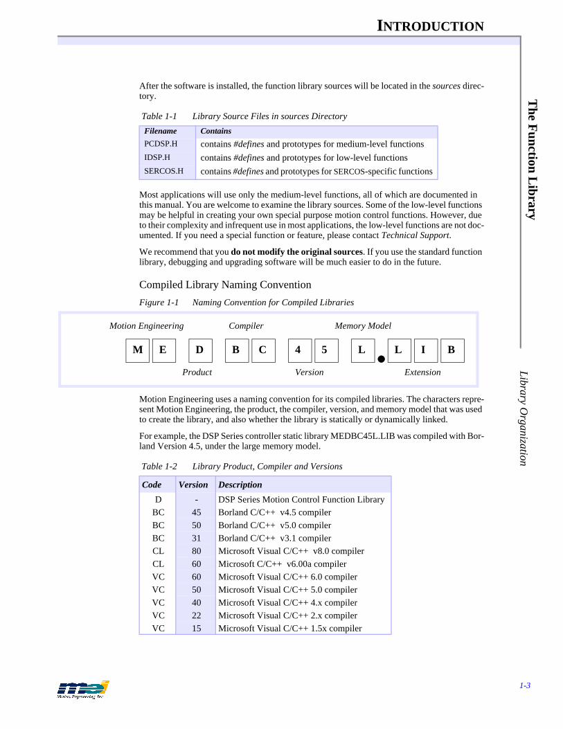
Figure 1-1 Naming Convention for Compiled Libraries
Motion Engineering uses a naming convention for its compiled libraries. The characters repre-sent Motion Engineering, the product, the compiler, version, and memory model that was used to create the library, and also whether the library is statically or dynamically linked.
For example, the DSP Series controller static library MEDBC45L.LIB was compiled with Bor-land Version 4.5, under the large memory model.
Table 1-1 Library Source Files in sources Directory
Filename Contains
PCDSP.H contains #defines and prototypes for medium-level functionsIDSP.H contains #defines and prototypes for low-level functionsSERCOS.H contains #defines and prototypes for SERCOS-specific functions
Table 1-2 Library Product, Compiler and Versions
Code Version Description
D - DSP Series Motion Control Function LibraryBC 45 Borland C/C++ v4.5 compilerBC 50 Borland C/C++ v5.0 compilerBC 31 Borland C/C++ v3.1 compilerCL 80 Microsoft Visual C/C++ v8.0 compilerCL 60 Microsoft C/C++ v6.00a compilerVC 60 Microsoft Visual C/C++ 6.0 compilerVC 50 Microsoft Visual C/C++ 5.0 compilerVC 40 Microsoft Visual C/C++ 4.x compilerVC 22 Microsoft Visual C/C++ 2.x compilerVC 15 Microsoft Visual C/C++ 1.5x compiler
M E D B C 4 5 L L I B
Motion Engineering
Product
Compiler
Version
Memory Model
Extension
INTRODUCTION
1-4
The
Fun
ctio
n L
ibra
ryLi
brar
y O
rgan
izat
ion
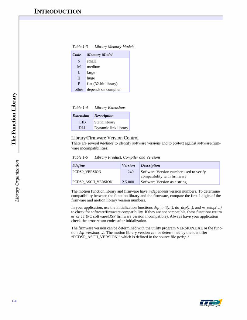
Library/Firmware Version ControlThere are several #defines to identify software versions and to protect against software/firm-ware incompatibilities:
The motion function library and firmware have independent version numbers. To determine compatibility between the function library and the firmware, compare the first 2 digits of the firmware and motion library version numbers.
In your application, use the initialization functions dsp_init(…), do_dsp(…), and m_setup(…) to check for software/firmware compatibility. If they are not compatible, these functions return error 11 (PC software/DSP firmware version incompatible). Always have your application check the error return codes after initialization.
The firmware version can be determined with the utility program VERSION.EXE or the func-tion dsp_version(…). The motion library version can be determined by the identifier “PCDSP_ASCII_VERSION,” which is defined in the source file pcdsp.h.
Table 1-3 Library Memory Models
Code Memory Model
S smallM mediumL largeH hugeF flat (32-bit library)
other depends on compiler
Table 1-4 Library Extensions
Extension Description
LIB Static libraryDLL Dynamic link library
Table 1-5 Library Product, Compiler and Versions
#define Version Description
PCDSP_VERSION 240 Software Version number used to verify compatibility with firmware
PCDSP_ASCII_VERSION 2.5.000 Software Version as a string
The F
unction Library
INTRODUCTION
1-5
Library Com
pilation
Library Compilation
To Recompile the Function LibraryPlease consult the operating system/compiler-specific Release Note for information about re-compiling the function library.
To Compile under Unsupported Operating SystemsThere are commonly 2 areas of difficulty in porting the function library to other operating sys-tems typically appear: hardware access and different integer sizes.
1. Hardware accessUnder some operating systems the C compilers don't provide in-port or out-port instruc-tions, requiring some assembly support. In this case, modifying the functions DSP_IN and DSP_OUT would be necessary. In other cases, systems can further deny I/O access through hardware, forcing the system designer to either provide special privilege to that program or write a device driver.
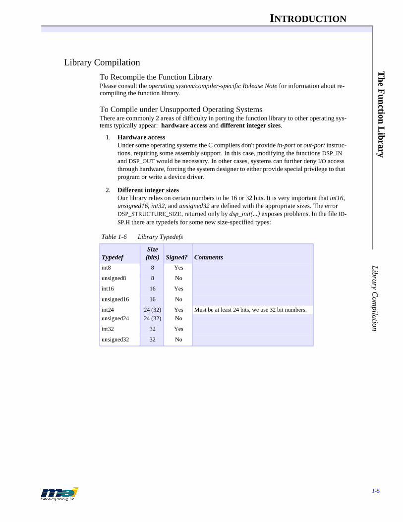
2. Different integer sizesOur library relies on certain numbers to be 16 or 32 bits. It is very important that int16, unsigned16, int32, and unsigned32 are defined with the appropriate sizes. The error DSP_STRUCTURE_SIZE, returned only by dsp_init(...) exposes problems. In the file ID-SP.H there are typedefs for some new size-specified types:
Table 1-6 Library Typedefs
TypedefSize (bits) Signed? Comments
int8 8 Yes
unsigned8 8 No
int16 16 Yes
unsigned16 16 No
int24 24 (32) Yes Must be at least 24 bits, we use 32 bit numbers.unsigned24 24 (32) No
int32 32 Yes
unsigned32 32 No
INTRODUCTION
1-6
App
licat
ion
Dev
elop
men
t Tip
sB
efor
e W
ritin
g A
ny C
ode
Application Development Tips
Before Writing Any CodeDo not start writing your application until you have:
1. Installed the DSP Series controller 2. Commanded two-point motion with either Motion Console or the SETUP.EXE program 3. Successfully compiled and executed the HELLODSP.C program
Writing the application requires a basic understanding of the controller’s design, the hardware (both the controller and external devices), the firmware, and the software. Most of the infor-mation you will need to create your application is available in this manual and on the Applica-tions distribution CD-ROM. Start by taking a careful look at chapters 2 and 3. Both chapters are logically organized into sections of functions that support specific features. Also, look over the sample programs on the Applications distribution diskette.
Before programming, configure and thoroughly test the hardware with Motion Console (for Windows-based systems) or the SETUP.EXE program (for DOS-based systems). Be sure that you can perform two-point motion with all of your motors before you write any code.
Tip: If you do not have motors connected to the DSP controller, you can simulate motors by configuring the axes as open-loop steppers. The programming is the same for servo and step motors. Refer to the controller’s installation manual for more details.
Coding RecommendationsWe recommend several techniques that can help you write and debug your applications quickly and easily.
1. Write small programs to test individual features, And then combine the small code modules into the larger application. If a feature doesn’t work properly in the application code, you can always go back to the small programs to figure out what to do next.
2. Build debugging tools into your code. Most functions return error codes, so write code to check the error codes. Also, the library contains many functions that examine the current condition of the con-troller, such as get_command(...), get_position(...), get_error(...), get_dac_output(...), axis_status(...), axis_state(...) and axis_source(...).
3. Make the application as simple as possible. Most applications do not require interrupts, so don’t use interrupts unless you really, re-ally need them. Writing code that uses interrupts can become very difficult very quickly.
Homing Routines Can Be ComplicatedAlmost every application requires a homing routine, because immediately after a system is turned on, the controller does not know the physical locations of the motors. You use a homing routine to calibrate the physical location of the motors with the absolute coordinates tracked by the DSP controller. You use different algorithms for a homing routine depending upon the me-chanical system that you are using. Note that when planning a homing routine, the most impor-tant thing is the repeatability of the home location.
Quite often, the homing routine is one of the most complicated portions of a motion applica-tion, so be methodical. Refer to the Sample Applications Distribution on the CD-ROM and the Applications distribution on the CD-ROM for example homing programs.

Application D
evelopment T
ips
INTRODUCTION
1-7
Coding R
ecomm
endations
Use the Error CodesIf any function doesn't work as expected, have your application check the function's return code, because most functions in the library return an integer error code. An error code of 0 (de-fined as DSP_OK in pcdsp.h) indicates success of the last operation; any other nonzero code indicates a problem.
It is very important to check the error code returned by the initial call to dsp_init(...), do_dsp(...), or serc_reset(…). If dsp_init(...), do_dsp(...), or serc_reset(…) fails, it usually indi-cates a hardware or configuration problem which will likely prevent any motion to be per-formed correctly after dsp_init(...) or do_dsp(...) fails.
Look for Exception EventsDSP Series controllers have several built-in safety features, which include hardware limit in-puts, home inputs, amp faults inputs, software position limits, position error limits, and encoder broken wire detection. All of these safety features can be examined and configured using the SETUP.EXE program or Motion Console. The firmware stores default configurations for the safety features.
Always check the configurations for the limit inputs, home inputs, amp faults inputs, software position limits, and position error limits. If these inputs are not connected, they may float and trigger unexpected exception events in the controller. Configure all unused limit inputs, home inputs, amp faults inputs, software position limits, or position error limits for No Event.
Save & Maintain Your FirmwareThe DSP Series controller has nonvolatile memory which contains the firmware, which con-tains executable code and configuration information. The controller’s behavior and software compatibility are determined by the firmware configuration, because at start-up, the firmware is loaded into the DSP. You can easily download firmware to your controller, or upload the firmware contents to a disk file.
Note that it is your responsibility to maintain the appropriate firmware file(s) for your ma-chine’s configuration. Also note that MEI always ships the DSP Series controllers with the lat-est software and firmware.
When building several machines, it is important to save the current firmware configuration to a disk file. Future DSP Series controllers can be configured using one of the following meth-ods:
Method 1: Download a configured firmware fileConfigure the controller’s firmware with SETUP.EXE, Motion Console, or your applica-tion program. Next upload the configured firmware to a disk file. When you build ma-chines in the future, simply download the configured firmware file from the disk to the controller.
Method 2: Download a default firmware file and then configure itSave a copy of the default firmware files from the distribution CD-ROM. When you build machines in the future, simply download the default firmware file from the dis-kette to the controller. Next configure the controller’s firmware with SETUP.EXE, Mo-tion Console, or your application program.
Method 3: Have your application download a firmware file and configure itEvery time that the machine is turned on, download firmware from your application to the controller. This method makes it easy to upgrade software and firmware on ma-chines in the field. The only restriction is that the firmware can only be reconfigured 10,000 times.
INTRODUCTION
1-8
App
licat
ion
Dev
elop
men
t Tip
sC
odin
g R
ecom
men
datio
ns
To upload or download firmware, use the SETUP.EXE program or Motion Console. To download firmware and to zero the DAC offsets, use the CONFIG.EXE program.
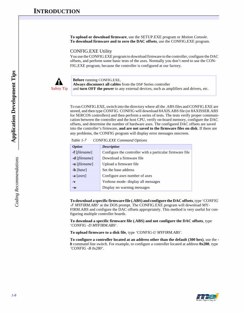
CONFIG.EXE UtilityYou use the CONFIG.EXE program to download firmware to the controller, configure the DAC offsets, and perform some basic tests of the axes. Normally you don’t need to use the CON-FIG.EXE program, because the controller is configured at our factory.
To run CONFIG.EXE, switch into the directory where all the .ABS files and CONFIG.EXE are stored, and then type CONFIG. CONFIG will download 8AXIS.ABS file (or 8AXISSER.ABS for SERCOS controllers) and then perform a series of tests. The tests verify proper communi-cation between the controller and the host CPU, verify on-board memory, configure the DAC offsets, and determine the number of hardware axes. The configured DAC offsets are saved into the controller’s firmware, and are not saved to the firmware files on disk. If there are any problems, the CONFIG program will display error messages onscreen.
To download a specific firmware file (.ABS) and configure the DAC offsets, type ‘CONFIG -F MYFIRM.ABS‘ at the DOS prompt. The CONFIG.EXE program will download MY-FIRM.ABS and configure the DAC offsets appropriately. This method is very useful for con-figuring multiple controller boards.
To download a specific firmware file (.ABS) and not configure the DAC offsets, type ‘CONFIG -D MYFIRM.ABS‘.
To upload firmware to a disk file, type ‘CONFIG-U MYFIRM.ABS’.
To configure a controller located at an address other than the default (300 hex), use the -b command line switch. For example, to configure a controller located at address 0x280, type ’CONFIG -B 0x280’.
Table 1-7 CONFIG.EXE Command Options
Option Description
-f [filename] Configure the controller with a particular firmware file-d [filename] Download a firmware file -u [filename] Upload a firmware file -b [base] Set the base address-a [axes] Configure axes number of axes-v Verbose mode- display all messages-w Display no warning messages
Before running CONFIG.EXE, Always disconnect all cables from the DSP Series controller and turn OFF the power to any external devices, such as amplifiers and drivers, etc.Safety Tip

Application D
evelopment T
ips
INTRODUCTION
1-9
Troubleshooting Tips
Troubleshooting TipsFinding the cause of the problem is often more difficult than the solution.
Isolate the Problem:
1. If the problem occurs during the execution of your application, then try to create the smallest piece of code that reproduces the problem.
2. Run the SETUP.EXE program or Motion Console for a second opinion. (The position sta-tus and axis status screens are the most helpful.) Note that the SETUP.EXE program and Motion Console use the same function library as your application does.
Determine if it is a hardware or software problem:
1. If the problem is in the hardware, find which signals are at fault. Is it the user I/O, ded-icated I/O, the +/-10 V control signal, the step/direction signals, the encoder inputs, or the analog inputs?
Does the problem occur when the DSP Series controller is connected or disconnected from the external devices?
Can the problem be reproduced on another computer?
Can the problem be reproduced using another DSP Series controller?
2. Is the problem consistent or random?
Use an oscilloscope to look at the integrity of the signals. Are the signals clean or noisy?
Do the signals look the same when connected or disconnected from the external devic-es?
Are the signals noisy when the motor is moving or standing still. Or when the amplifier is powered on or off?
If the problem is in software, try to reproduce the problem with the smallest piece of code pos-sible. Next fax this small piece of code along with a description of the problem to MEI. Be spe-cific about the problem and any other information that is pertinent. Don’t forget to include your name, phone and fax number, and date.

INTRODUCTION
1-10
Mot
ion
Dev
elop
er’s
Sup
port
Pro
gram
To G
et S
oftw
are
Upd
ates
Motion Developer’s Support ProgramMotion Engineering takes technical support seriously. We want your system to work! To con-tinue to provide the best possible applications support, we have created the Motion Developer’s Support Program. Participation in the Motion Developer’s Support Program is required in or-der to receive application support. Contact MEI for more information.
MEI’s Motion Developer’s Support Program ensures that your critical project will receive the utmost applications support for timely problem resolution and faster development.
The Motion Developer’s Support Program includes:
One year of 24 hour/day, 7 day/week application technical support by telephone, e-mail, and/or fax (weekends and holidays included)
Priority access to application engineers with response in the same business day
Updated Motion Developer’s Kit (MDK) - provided on CD-ROM. This includes MEI’s DSP Series development tools, libraries, and sample code for Windows NT, Windows 95/98, and Windows 3.x with the current MEI features, functions, and bug fixes.
One year of software maintenance and updates for MDK software, tools, libraries, and sample applications code.
To Get Software UpdatesMEI periodically releases new software/firmware versions. New features are implemented, performance enhanced, and new applications developed. The latest firmware/software releas-es are available on our FTP site at ftp://ftp.motioneng.com.
The DSP Series controller has non-volatile memory space to store the firmware and configu-ration parameters. All of the DSP Series controllers are compatible with the latest firmware and software versions. Firmware can be easily downloaded to the controller with CON-FIG.EXE.
Future Controller PurchasesMEI ships the DSP Series controllers with the latest software, firmware, and on-board pro-grammable logic. When building multiple machines, we recommend that you save a config-ured version of your firmware to a diskette. The next time you build a machine, simply load that firmware (from diskette) to the DSP Series controller using the CONFIG.EXE program. This method is easiest.
We are constantly adding new features and improving the capability of our controllers, by re-vising the hardware and programmable logic to meet increased application demands. All future hardware/programmable logic revisions are backwards-compatible with older software and firmware revisions, and new features can be enabled if you start using the latest versions of software and firmware.
Table 1-8 Contacting MEI Technical Support
24-hour support (805) 681-3300
Fax (805) 681-3311
e-mail [email protected]
Motion D
eveloper’s Support Program
INTRODUCTION VERSIO
N.EXE U
tility
VERSION.EXE UtilityThe VERSION program reads the hardware identity, PROM version (on-board logic), and the firmware version from the controller and displays them to the screen. The firmware version and option numbers can be read directly from your application code with the functions dsp_version(...) and dsp_option(...).
Firmware VersionsMEI always ships the DSP controllers with the latest software and firmware. The firmware, software and Motion Console all have a version check built into the code. If the library version is incompatible with the firmware version, controller status will be listed as "bad" in Motion Console’s Controller List and the controller will be inaccessible.
If you wish to use an earlier version of the firmware on a newly purchased controller, or if you have an older controller and want to use a new firmware version, run the CONFIG program as described in the section in CONFIG.EXE Board Configuration Program, or use the Motion Console application.
Note that current firmware versions are available 24 hours a day on Motion Engineering’s FTP site (ftp.motioneng.com). Files for downloading are located in the /pub directory.
1-11

INTRODUCTION
1-12
Mot
ion
Dev
elop
er’s
Sup
port
Pro
gram
Firm
war
e Ve
rsio
ns
2-1
CHAPTER 2 CONFIGURATION FUNCTIONS
This chapter describes the medium-level functions used for configuration, logically organized into topics that support specific features. The function prototypes are in PCDSP.H.
CONFIGURATION FUNCTIONS
2-2
Qui
ck L
ist
Con
figur
atio
n F
unct
ions
Quick List
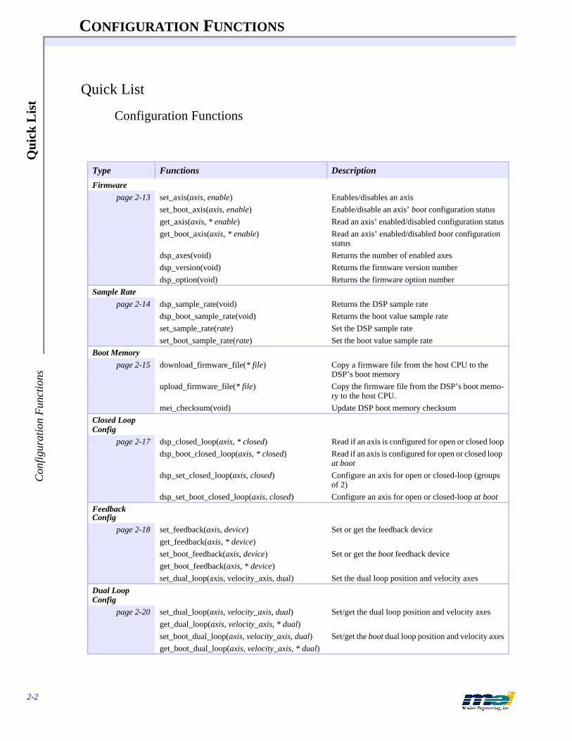
Configuration Functions
Type Functions Description
Firmwarepage 2-13 set_axis(axis, enable) Enables/disables an axis
set_boot_axis(axis, enable) Enable/disable an axis’ boot configuration statusget_axis(axis, * enable) Read an axis’ enabled/disabled configuration statusget_boot_axis(axis, * enable) Read an axis’ enabled/disabled boot configuration
statusdsp_axes(void) Returns the number of enabled axesdsp_version(void) Returns the firmware version numberdsp_option(void) Returns the firmware option number
Sample Ratepage 2-14 dsp_sample_rate(void) Returns the DSP sample rate
dsp_boot_sample_rate(void) Returns the boot value sample rateset_sample_rate(rate) Set the DSP sample rateset_boot_sample_rate(rate) Set the boot value sample rate
Boot Memorypage 2-15 download_firmware_file(* file) Copy a firmware file from the host CPU to the
DSP’s boot memoryupload_firmware_file(* file) Copy the firmware file from the DSP’s boot memo-
ry to the host CPU. mei_checksum(void) Update DSP boot memory checksum
Closed Loop Config
page 2-17 dsp_closed_loop(axis, * closed) Read if an axis is configured for open or closed loopdsp_boot_closed_loop(axis, * closed) Read if an axis is configured for open or closed loop
at bootdsp_set_closed_loop(axis, closed) Configure an axis for open or closed-loop (groups
of 2)dsp_set_boot_closed_loop(axis, closed) Configure an axis for open or closed-loop at boot
Feedback Config
page 2-18 set_feedback(axis, device) Set or get the feedback deviceget_feedback(axis, * device)set_boot_feedback(axis, device) Set or get the boot feedback deviceget_boot_feedback(axis, * device)set_dual_loop(axis, velocity_axis, dual) Set the dual loop position and velocity axes
Dual Loop Config
page 2-20 set_dual_loop(axis, velocity_axis, dual) Set/get the dual loop position and velocity axesget_dual_loop(axis, velocity_axis, * dual)set_boot_dual_loop(axis, velocity_axis, dual) Set/get the boot dual loop position and velocity axesget_boot_dual_loop(axis, velocity_axis, * dual)
CONFIGURATION FUNCTIONS
2-3
Quick L
ist C
onfiguration Functions
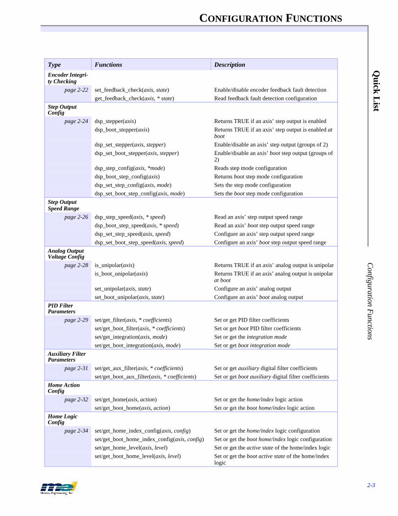
Encoder Integri-ty Checking
page 2-22 set_feedback_check(axis, state) Enable/disable encoder feedback fault detectionget_feedback_check(axis, * state) Read feedback fault detection configuration
Step Output Config
page 2-24 dsp_stepper(axis) Returns TRUE if an axis’ step output is enableddsp_boot_stepper(axis) Returns TRUE if an axis’ step output is enabled at
bootdsp_set_stepper(axis, stepper) Enable/disable an axis’ step output (groups of 2)dsp_set_boot_stepper(axis, stepper) Enable/disable an axis’ boot step output (groups of
2)dsp_step_config(axis, *mode) Reads step mode configurationdsp_boot_step_config(axis) Returns boot step mode configurationdsp_set_step_config(axis, mode) Sets the step mode configurationdsp_set_boot_step_config(axis, mode) Sets the boot step mode configuration
Step Output Speed Range
page 2-26 dsp_step_speed(axis, * speed) Read an axis’ step output speed rangedsp_boot_step_speed(axis, * speed) Read an axis’ boot step output speed rangedsp_set_step_speed(axis, speed) Configure an axis’ step output speed rangedsp_set_boot_step_speed(axis, speed) Configure an axis’ boot step output speed range
Analog Output Voltage Config
page 2-28 is_unipolar(axis) Returns TRUE if an axis’ analog output is unipolaris_boot_unipolar(axis) Returns TRUE if an axis’ analog output is unipolar
at bootset_unipolar(axis, state) Configure an axis’ analog outputset_boot_unipolar(axis, state) Configure an axis’ boot analog output
PID Filter Parameters
page 2-29 set/get_filter(axis, * coefficients) Set or get PID filter coefficientsset/get_boot_filter(axis, * coefficients) Set or get boot PID filter coefficientsset/get_integration(axis, mode) Set or get the integration modeset/get_boot_integration(axis, mode) Set or get boot integration mode
Auxiliary Filter Parameters
page 2-31 set/get_aux_filter(axis, * coefficients) Set or get auxiliary digital filter coefficientsset/get_boot_aux_filter(axis, * coefficients) Set or get boot auxiliary digital filter coefficients
Home Action Config
page 2-32 set/get_home(axis, action) Set or get the home/index logic actionset/get_boot_home(axis, action) Set or get the boot home/index logic action
Home Logic Config
page 2-34 set/get_home_index_config(axis, config) Set or get the home/index logic configurationset/get_boot_home_index_config(axis, config) Set or get the boot home/index logic configurationset/get_home_level(axis, level) Set or get the active state of the home/index logicset/get_boot_home_level(axis, level) Set or get the boot active state of the home/index
logic
Type Functions Description
CONFIGURATION FUNCTIONS
2-4
Qui
ck L
ist
Con
figur
atio
n F
unct
ions
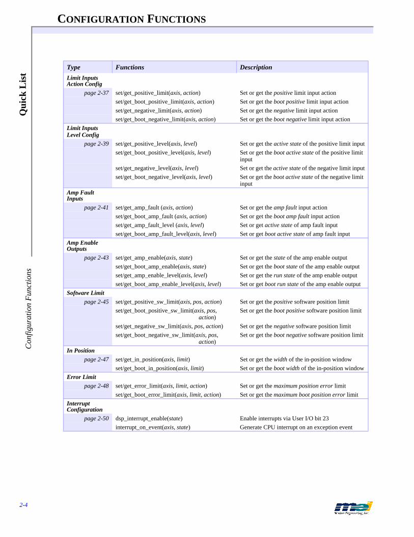
Limit Inputs Action Config
page 2-37 set/get_positive_limit(axis, action) Set or get the positive limit input actionset/get_boot_positive_limit(axis, action) Set or get the boot positive limit input actionset/get_negative_limit(axis, action) Set or get the negative limit input actionset/get_boot_negative_limit(axis, action) Set or get the boot negative limit input action
Limit Inputs Level Config
page 2-39 set/get_positive_level(axis, level) Set or get the active state of the positive limit inputset/get_boot_positive_level(axis, level) Set or get the boot active state of the positive limit
inputset/get_negative_level(axis, level) Set or get the active state of the negative limit inputset/get_boot_negative_level(axis, level) Set or get the boot active state of the negative limit
inputAmp Fault Inputs
page 2-41 set/get_amp_fault (axis, action) Set or get the amp fault input actionset/get_boot_amp_fault (axis, action) Set or get the boot amp fault input actionset/get_amp_fault_level (axis, level) Set or get active state of amp fault inputset/get_boot_amp_fault_level(axis, level) Set or get boot active state of amp fault input
Amp Enable Outputs
page 2-43 set/get_amp_enable(axis, state) Set or get the state of the amp enable outputset/get_boot_amp_enable(axis, state) Set or get the boot state of the amp enable outputset/get_amp_enable_level(axis, level) Set or get the run state of the amp enable outputset/get_boot_amp_enable_level(axis, level) Set or get boot run state of the amp enable output
Software Limitpage 2-45 set/get_positive_sw_limit(axis, pos, action) Set or get the positive software position limit
set/get_boot_positive_sw_limit(axis, pos, action)
Set or get the boot positive software position limit
set/get_negative_sw_limit(axis, pos, action) Set or get the negative software position limitset/get_boot_negative_sw_limit(axis, pos,
action)Set or get the boot negative software position limit
In Positionpage 2-47 set/get_in_position(axis, limit) Set or get the width of the in-position window
set/get_boot_in_position(axis, limit) Set or get the boot width of the in-position windowError Limit
page 2-48 set/get_error_limit(axis, limit, action) Set or get the maximum position error limitset/get_boot_error_limit(axis, limit, action) Set or get the maximum boot position error limit
Interrupt Configuration
page 2-50 dsp_interrupt_enable(state) Enable interrupts via User I/O bit 23interrupt_on_event(axis, state) Generate CPU interrupt on an exception event
Type Functions Description

CONFIGURATION FUNCTIONS
2-5
Quick L
ist SE
RC
OS F
unctions
SERCOS Functions
Type Functions Descriptions
Initialization
page 2-53 serc_reset(baud, ndrives, * dinfo) Resets controller & initializes SERCOS get_sercos_phase(* phase) Reads the SERCOS ring initialization phase
Configure Phase 2/3 IDNs
page 2-56 configure_phase2_idns(nidns, * didns) Specifies IDNs to be set during phase 2 initconfigure_phase3_idns(nidns, * didns) Specifies IDNs to be set during phase 3 init
Cyclic Data Configuration
page 2-58 configure_at_data(natdata, * at_data) Specifies IDNs to be placed in the ATconfigure_mdt_data(nmdtdata, *
mdt_data)Specifies IDNs to be placed in the MDT
Drive Addresses
page 2-60 get_drive_addresses(baud, * ndrives, * dr_addrs)
Determines the addresses for SERCOS nodes
Changing Op Modes
page 2-61 change_operation_mode(axis, mode) Changes the drive’s operation modeRead/Write IDN
page 2-62 set_idn(axis, idn, value) Writes an IDN value to a SERCOS nodeget_idn(axis, idn, * value) Reads an IDN value from a SERCOS nodeget_idn_size(axis, idn, * size) Reads element 7’s size from the specified IDNget_idn_string(axis, dr_addr, idn, * str) Reads a string from an IDNget_idn_attributes(axis, idn, * attr) Reads an IDN’s attributes
Read/Write Multiple IDNs
page 2-64 set_idns(axis, dr_addr, idns, * idns) Writes an array of IDN values to a SERCOS nodeget_idns(axis, dr_addr, firstidn, idns,
* idns)Reads an array of IDN values from a SERCOS node
Procedures
page 2-66 start_exec_procedure(axis, procedure) Starts a SERCOS drive procedurecancel_exec_procedure(axis, proce-dure)
Cancels a SERCOS drive procedure
exec_procedure_done(axis, procedure, * done)
Determines a drive procedure’s completion
Read/Write Cyclic Data
page 2-68 read_cyclic_at_data(axis, offset) Reads cyclic data from an Amplifier Telegramread_cyclic_mdt_data(axis, offset) Reads cyclic data from the Master Data Telegramwrite_cyclic_mdt_data(axis, offset, data)
Writes cyclic data to the Master Data Telegram
Enable/Disable LED
page 2-70 turn_on_sercos_led(void) Enables the LED from the output moduleturn_off_sercos_led(void) Disables the LED from the output module
Drive Status/Reset
page 2-71 get_drive_status(axis, * status) Read the SERCOS node’s status wordreset_sercos_drive(axis) Resets a SERCOS node
Diagnostics
page 2-73 get_class_1_diag(axis, * code, * msg) Read class 1 diagnostic message from driveget_class_2_diag(axis, * code, * msg) Read class 2 diagnostic message from drive
CONFIGURATION FUNCTIONS
2-6
Qui
ck L
ist
type
defs
and
#de
fines
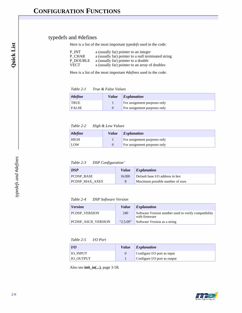
typedefs and #definesHere is a list of the most important typedefs used in the code:
P_INT a (usually far) pointer to an integerP_CHAR a (usually far) pointer to a null terminated stringP_DOUBLE a (usually far) pointer to a doubleVECT a (usually far) pointer to an array of doubles
Here is a list of the most important #defines used in the code:
Also see init_io(...), page 3-58.
Table 2-1 True & False Values
#define Value Explanation
TRUE 1 For assignment purposes onlyFALSE 0 For assignment purposes only
Table 2-2 High & Low Values
#define Value Explanation
HIGH 1 For assignment purposes onlyLOW 0 For assignment purposes only
Table 2-3 DSP Configuration’
DSP Value Explanation
PCDSP_BASE 0x300 Default base I/O address in hexPCDSP_MAX_AXES 8 Maximum possible number of axes
Table 2-4 DSP Software Version
Version Value Explanation
PCDSP_VERSION 240 Software Version number used to verify compatibility with firmware
PCDSP_ASCII_VERSION “2.5.09” Software Version as a string
Table 2-5 I/O Port
I/O Value Explanation
IO_INPUT 0 Configure I/O port as inputIO_OUTPUT 1 Configure I/O port as output

CONFIGURATION FUNCTIONS
2-7
Quick L
ist typedefs and #defines
Also see axis_state(...), page 3-45.
Also see axis_status(...), page 3-44.
Also see axis_source(...), page 3-46.
Table 2-6 Events
Exception Events Value Explanation
NO_EVENT 0 Ignore a conditionNEW_FRAME 2 Begin execution of the next sequenced frameCHECK_FRAMES 6 Used internally to generate e-stops when the list is emptySTOP_EVENT 8 Generate a Stop EventE_STOP_EVENT 10 Generate an E-Stop EventABORT_EVENT 14 Disable PID control, and disable the amp enable output
Table 2-7 Axis Status
Status Value Explanation
IN_SEQUENCE 0x0010 Frame(s) left to be triggeredIN_POSITION 0x0020 Within allowable position error windowIN_MOTION 0x0040 Command velocity is non-zeroDIRECTION 0x0080 Sign of command velocity (true == negative)FRAMES_LEFT 0x0100 Frames to be executed for an axis
Table 2-8 Axis Source
Source Value Explanation
ID_NONE 0 No event has occurredID_HOME_SWITCH 1 Home logic was activatedID_POS_LIMIT 2 Positive limit input was activatedID_NEG_LIMIT 3 Negative limit input was activatedID_AMP_FAULT 4 Amplifier fault input was activatedID_X_NEG_LIMIT 7 Software negative travel limit was exceededID_X_POS_LIMIT 8 Software positive travel limit was exceededID_ERROR_LIMIT 9 Software position error was exceededID_PC_COMMAND 10 CPU has commanded a Stop, E-Stop, Abort, or
Clear StatusID_OUT_OF_FRAMES 11 Attempted the next frame with no frame presentID_FEEDBACK_FAULT 12 Broken wire was detectedID_FEEDBACK_ILLEGAL_STATE 13 Improper feedback logic state was detectedID_AXIS_COMMAND 14 Event was triggered by another axis
CONFIGURATION FUNCTIONS
2-8
Qui
ck L
ist
type
defs
and
#de
fines
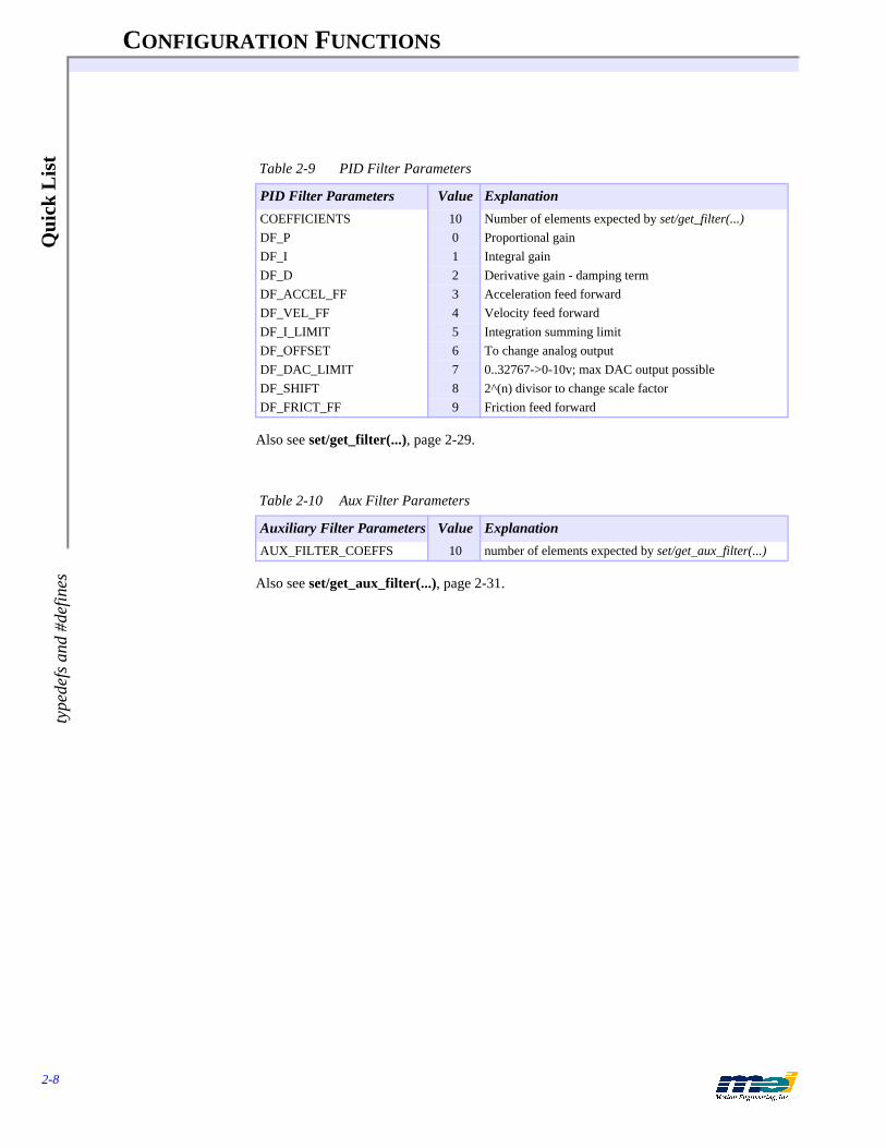
Also see set/get_filter(...), page 2-29.
Also see set/get_aux_filter(...), page 2-31.
Table 2-9 PID Filter Parameters
PID Filter Parameters Value Explanation
COEFFICIENTS 10 Number of elements expected by set/get_filter(...)DF_P 0 Proportional gainDF_I 1 Integral gainDF_D 2 Derivative gain - damping termDF_ACCEL_FF 3 Acceleration feed forwardDF_VEL_FF 4 Velocity feed forwardDF_I_LIMIT 5 Integration summing limitDF_OFFSET 6 To change analog outputDF_DAC_LIMIT 7 0..32767->0-10v; max DAC output possibleDF_SHIFT 8 2^(n) divisor to change scale factorDF_FRICT_FF 9 Friction feed forward
Table 2-10 Aux Filter Parameters
Auxiliary Filter Parameters Value Explanation
AUX_FILTER_COEFFS 10 number of elements expected by set/get_aux_filter(...)

CONFIGURATION FUNCTIONS
2-9
Quick L
ist E
rror #defines
Error #defines
Table 2-11 Error #defines
Error defines Value Explanation
MAX_ERROR_LEN 150 Max length for error message stringDSP_OK 0 No errorDSP_NOT_INITIALIZED 1 Did you call dsp_init(...)?DSP_NOT_FOUND 2 DSP not found at the given I/O addressDSP_INVALID_AXIS 3 Illegal axis specifiedDSP_ILLEGAL_ANALOG 4 Illegal analog channel specifiedDSP_ILLEGAL_IO 5 Illegal I/O port/bit specifiedDSP_OUT_OF_MEMORY 6 Out of internal DSP memoryDSP_FRAME_UNALLOCATED 7 Downloaded an unallocated frameDSP_ILLEGAL_PARAMETER 8 Illegal Accel, Velocity or JerkDSP_ILLEGAL_CONVERSION 9 Zero CountsPerDistance or
SecondsPerPeriodDSP_FRAME_NOT_CONNECTED 10 Unloaded an unconnected frameDSP_FIRMWARE_VERSION 11 PC software v PCDSP_ASCII_VERSION/
DSP firmware version incompatibleDSP_ILLEGAL_TIMER 12 Invalid 8254 timer was selectedDSP_STRUCTURE_SIZE 13 FRAME Structure size is incorrect; a porting
problem is suspectedDSP_TIMEOUT_ERROR 14 The wait for a transfer block exceeded the al-
lowable timeDSP_RESOURCE_IN_USE 15 Libraries’ Global Resource is in useDSP_CHECKSUM 16 Boot memory checksum errorDSP_CLEAR_STATUS 17 Can’t clear statusDSP_NO_MAP 18 Coordinated motion not inititalizedDSP_NO_ROOM 19 Out of DSP FIFO buffer spaceDSP_BAD_FIRMWARE_FILE 20 Specified firmware file is corrupt or nonex-
istentDSP_ILLEGAL_ENCODER_CHANNEL 21 Illegal encoder channel specifiedDSP_FUNCTION_NOT_AVAILABLE 22 Function is no longer availableDSP_NO_EXTERNAL_BUFFER 23 External buffer is full or does not existDSP_NT_DRIVER 24 Windows NT DSPIO Driver not foundDSP_FUNCTION_NOT_APPLICABLE 25 Function is not applicableDSP_NO_DISTANCE 26 Zero distance moveDSP_FIRMWARE_CHECKSUM 27 Firmware buffer checksum errorDSP_FEATURE_NOT_SUPPORTED 28 Requested feature not supported by current
software/firmwareDSP_ENVIRONMENT_NOT_SUPPORTED 29 Requested function not supported by current
compiler or Operating SystemDSP_SERCOS_SLAVE_ERROR 100 General error in slave’s service containerDSP_SERCOS_INVALID_PARAM 101 Invalid parameter passed to serc_reset()DSP_SERCOS_DISTORTED 102 Data is distortedDSP_SERCOS_LOOP_OPEN 103 SERCOS loop is openDSP_SERCOS_EARLY 104 Master Sync Telegram was sent too earlyDSP_SERCOS_LATE 105 Master Sync Telegram was sent too late

CONFIGURATION FUNCTIONS
2-10
Qui
ck L
ist
Err
or #
defin
es
Also see dsp_error(...), page 3-13.
DSP_SERCOS_MST_MISSING 106 Master Sync Telegram is missingDSP_SERCOS_DRIVE_INIT 107 Drive(s) not foundDSP_SERCOS_INVALID_DRIVE_TYPE 108 Invalid drive modeDSP_SERCOS_INVALID_DRIVE_NUMBER 109 Invalid number of drivesDSP_SERCOS_INVALID_DRIVE_ADDR 110 Invalid drive addressDSP_SERCOS_DUPLICATE_DRIVE_ADDR 111 Duplicate drive addressDSP_SERCOS_PROC_FAILURE 112 Procedure has failedDSP_SERCOS_AXIS_ASSIGNMENT 113 Axis is not assigned to a valid driveDSP_SERCOS_RESET 114 Use serc_reset(...) instead of dsp_reset(...)
with SERCOS controllersDSP_SERCOS_VARIABLE_READ 115 Use get_idn_string(...) to read variable length
stringsDSP_SERCOS_INVALID_IDN_AT 116 Invalid IDN in the AT cyclic dataDSP_SERCOS_INVALID_IDN_MDT 117 Invalid IDN in the MDT cyclic dataDSP_SERCOS_127_FAILURE 118 Drive is not able to enter phase 3DSP_SERCOS_128_FAILURE 119 Drive is not able to enter phase 4DSP_SERCOS_IDN_NOT_AVAILABLE 120 IDN is not supported in the driveDSP_SERCOS_NO_CHANNEL 121 Could not open a service channelDSP_SERCOS_ELEMENT_MISSING 122 IDN element not supported by driveDSP_SERCOS_SHORT_TRANS 123 Service channel transmission is too shortDSP_SERCOS_LONG_TRANS 124 Service channel transmission is too longDSP_SERCOS_STATIC_VAL 125 IDN element is staticDSP_SERCOS_WRITE_PROTECT 126 IDN element is write protectedDSP_SERCOS_MIN 127 Value is less than allowable rangeDSP_SERCOS_MAX 128 Value is greater than allowable rangeDSP_SERCOS_INVALID_DATA 129 Data is not validDSP_SERCOS_PROTOCOL 130 Protocol error in slaveDSP_SERCOS_HS_TIMEOUT 131 Service channel handshake timeoutDSP_SERCOS_BUSY 132 Slave’s BUSY_AT bit is onDSP_SERCOS_CMD 133 Drive set the command modification bitDSP_SERCOS_M_NOT_READY 134 Master’s M_BUSY bit is offDSP_SERCOS_SC_TIMEOUT 135 Service container timeout errorDSP_SERCOS_REC_ERR 136 Invalid service container transmissionDSP_SERCOS_INVALID_CYCLE_TIME 137 Cycle time is too shortDSP_SERCOS_USER_AT 138 Max cyclic user AT data was exceededDSP_SERCOS_USER_MDT 139 Max cyclic user MDT data was exceededDSP_SINCOM_TABLE_CREATION 200 SinCom table creation errorDSP_SINCOM_HEADER_CREATION 201 SinCom header creation errorDSP_SINCOM_NOT_POSSIBLE 202 Commutation not able to fit within SINCOM
tableDSP_SINCOM_NO_MOTION 203 SinCom initialization created no motionDSP_SINCOM_CURRENT_ERR 204 SinCom drive high-current warning
Table 2-11 Error #defines
Error defines Value Explanation

CONFIGURATION FUNCTIONS
2-11
Quick L
ist M
ore #defines
More #defines
Also see mei_link(...), page 3-73.
Also see set/get_integration(...), page 2-29.
Also see set/get_feedback(...), page 2-18.
Also see set/get_home_index_config(...), page 2-34.
Table 2-12 Master Slave Control
Link Value Explanation
LINK_ACTUAL 1 Actual position master slave controlLINK_COMMAND 2 Command position master slave control
Table 2-13 Integration Modes
Integration Modes Value Explanation
IM_STANDING 0 Integration active only when command velocity is zeroIM_ALWAYS 1 Integration is always active
Table 2-14 Feedback Devices
Feedback Devices Value Explanation
FB_ENCODER 0 Incremental encoder is used for actual positionFB_ANALOG 1 Analog input is used for actual positionFB_PARALLEL 2 User I/O (32 bits) is used for actual position
Table 2-15 Home/Index Configurations
Home/Index Configurations Value Explanation
HOME_ONLY 0 Home sensor only (active high or active low)LOW_HOME_AND_INDEX 1 Home sensor ANDed with index
(active low home, active high index)INDEX_ONLY 2 Index only (active high or active low)HIGH_HOME_AND_INDEX 3 Home sensor ANDed with index
(active high home, active high index)
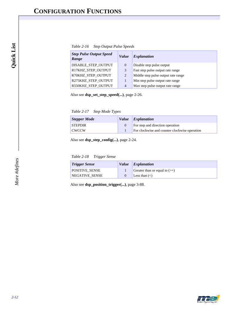
CONFIGURATION FUNCTIONS
2-12
Qui
ck L
ist
Mor
e #d
efin
es
Also see dsp_set_step_speed(...), page 2-26.
Also see dsp_step_config(...), page 2-24.
Also see dsp_position_trigger(...), page 3-88.
Table 2-16 Step Output Pulse Speeds
Step Pulse Output Speed Range Value Explanation
DISABLE_STEP_OUTPUT 0 Disable step pulse outputR17KHZ_STEP_OUTPUT 3 Fast step pulse output rate rangeR70KHZ_STEP_OUTPUT 2 Middle step pulse output rate rangeR275KHZ_STEP_OUTPUT 1 Min step pulse output rate rangeR550KHZ_STEP_OUTPUT 4 Max step pulse output rate range
Table 2-17 Step Mode Types
Stepper Mode Value Explanation
STEPDIR 0 For step and direction operationCWCCW 1 For clockwise and counter clockwise operation
Table 2-18 Trigger Sense
Trigger Sense Value Explanation
POSITIVE_SENSE 1 Greater than or equal to (>=)NEGATIVE_SENSE 0 Less than (<)

CONFIGURATION FUNCTIONS
2-13
Firm
ware
set_axis
Firmware
set_axis enables/disables an axisset_boot_axis enable/disable an axis’ boot configuration statusget_axis read an axis’ enabled/disabled configuration statusget_boot_axis read an axis’ enabled/disabled boot configuration statusdsp_axes returns the number of enabled axesdsp_version returns the firmware’s version numberdsp_option returns the firmware’s option number
SYNTAX set_axis(int16 axis, int16 enable)set_boot_axis(int16 axis, int16 enable)get_axis(int16 axis, int16 * enable)get_boot_axis(int16 axis, int16 * enable)
int16 dsp_axes(void)int16 dsp_version(void)int16 dsp_option(void)
PROTOTYPE IN pcdsp.h
DESCRIPTION In firmware version 2.4F4 or higher, there is only one firmware file: 8AXIS.ABS (or for SER-COS, 8AXISSER.ABS). This file contains the code necessary to control up to 8 axes. An axis can be enabled (enable = TRUE) or disabled (enable = FALSE) with set_axis(…). An axis’ enabled/disabled status can be read with get_axis(…). The boot axis configuration status can be set with set_boot_axis(…) and can be read with get_boot_axis(…). dsp_axes(...) simply returns the number of enabled axes. However, the number of axes re-turned by dsp_axes(…) may not be sequential.
The firmware has a 16-bit version and 16-bit option number for identification purposes. dsp_version(void) returns the integer version number and dsp_option(void) returns the inte-ger option number.
RETURN VALUES
Table 2-19 Firmware Version & Option Numbers
Function Label Bits Description
dsp_version(...) Version 4-15 Calculated by (dsp_version( ) / 1600.0)Revision 0-3 design changes represented as a character
dsp_option(...) Dev 15 1 for development, 0 for releaseSub-Revision 12-14 minor changes represented as a numberOption 0-11 optional firmware
Returnsset_axis(...)set_boot_axis(...)get_axis(...)get_boot_axis(...)
Error return codes (see Error Handling on page 3-13)
dsp_axes(...)dsp_version(...)dsp_option(...)
Values

CONFIGURATION FUNCTIONS
2-14
Sam
ple
Rat
eds
p_sa
mpl
e_ra
te
Sample Rate
dsp_sample_rate returns the number of samples per seconddsp_boot_sample_rate returns the boot value for the number of samples per secondset_sample_rate sets the number of samples per secondset_boot_sample_rate sets the number of samples per second in boot memory
SYNTAX int16 dsp_sample_rate(void)int16 dsp_boot_sample_rate(void)int16 set_sample_rate(unsigned16 rate)int16 set_boot_sample_rate(unsigned16 rate)
PROTOTYPE IN pcdsp.h
DESCRIPTION dsp_sample_rate(...) and dsp_boot_sample_rate(..) return the sample timer clock rate in samples per second. The default sample rate for all controllers is 1250 samples/second. This is a conservative sample rate but is more than adequate for most applications.set_sample_rate(...) and set_boot_sample_rate(..) alter the DSP's sample timer. Changing the sample rate will have a direct effect on the response of the system and may require the digital filter parameters to be adjusted. Generally, at higher sample rates the digital filter parameters will need to be lowered.
Also, a change in the sample rate will affect the calculation of the velocities and accelerations. However, the library will adjust the conversion factors according to changes in the sample rate. This guarantees that the units used by your program will be calculated correctly.
The firmware's execution time determines the maximum possible sample rate. If the sample rate is set too high (above 1500 Hz on 8 axis firmware) the firmware will run as fast as possible. In this case the sample rate set by set_sample_rate(...) and the actual sample rate of the DSP are different, and the velocities and accelerations will be executed incorrectly.
EXECUTION dsp_sample_rate(...)/ dsp_boot_sample_rate(..) performone transfer block read.set_sample_rate(...)/ set_boot_sample_rate(..) perform one transfer block write.
RETURN VALUES
Table 1-20 Max Sample Rate
Axis Sample Rate (Hz)1 71002 47003 35004 27005 23006 20007 17008 1500
Returnsdsp_sample_rate(...)dsp_boot_sample_rate(..)
Values
set_sample_rate(...)set_boot_sample_rate(..)
Error return codes (see Error Handling on page 3-13)

CONFIGURATION FUNCTIONS
2-15
Boot M
emory
download_firm
ware_file
Boot Memory
download_firmware_file copy a firmware file from the host CPU to the DSP’s boot memory
upload_firmware_file copy the firmware file from the DSP’s boot memory to the host CPU
mei_checksum update the DSP’s boot memory checksum
SYNTAX int16 download_firmware_file(char * file)int16 upload_firmware_file(char * file)unsigned16 mei_checksum(void)
PROTOTYPE IN pcdsp.h
DESCRIPTION download_firmware_file(...) copies a firmware file (.ABS) from the host CPU to the DSP’s boot memory and resets the controller, loading the firmware from boot memory to dynamic memory. After the file is downloaded, be sure to call mei_checksum(...).To copy a firmware file from the DSP’s boot memory to the host CPU, use upload_firmware_file(…).
mei_checksum(...) calculates the size of the data stored in boot memory, writes the calculated checksum into boot memory and returns the checksum (not an error code). mei_checksum(...) also performs a non-volatile storage into the flash boot memory (surface mount controllers only).
When dsp_init(...) or dsp_reset(...) are called, the checksum is recalculated and compared with the checksum stored in boot memory. If the checksums do not match, then error 16 (DSP_CHECKSUM) will be returned. If any of the 'boot' functions are called or the boot memory has been modified then mei_checksum(...) must be called, otherwise the next dsp_init(...) or dsp_reset(...) will fail.
All of the surface mount DSP Series controllers have flash RAM that stores the firmware and boot configuration. The flash RAM can be written to with mei_checksum(...) up to 10,000 times. The PC/DSP Series controllers have battery-backed RAM that stores the firmware and boot configuration, with no limitation on the number of times it can be written to.
RETURN VALUES
SEE ALSO dsp_init(...), dsp_reset(...)
SAMPLE CODE This code sets the boot configuration of the home sensor of axis 0 to trigger NO_EVENT and then calls checksum. The configuration does not take effect until the controller is reset.
# include <stdio.h># include "pcdsp.h"
int main(){
if (dsp_init(PCDSP_BASE))/* any problems initializing? */return dsp_error;/* just terminate the program. */
set_boot_home(0, NO_EVENT);mei_checksum();
return dsp_error ; /* global variable provided by the library */}
Returnsdownload_firmware_file(...)upload_firmware_file(...)mei_checksum(...)
Error return codes (see Error Handling on page 3-13)

CONFIGURATION FUNCTIONS
2-16
Boo
t Mem
ory
dow
nloa
d_fir
mw
are_
file
NOTES The checksum is a required setup for the health check that dsp_init(...) performs. When the boot memory checksum doesn't agree with the saved checksum then there could be problems communicating with the controller, or the controller itself may not have been reset properly. See the Installation Manual for instructions about how to download firmware.

CONFIGURATION FUNCTIONS
2-17
Closed L
oop Configuration
dsp_closed_loop
Closed Loop Configuration
dsp_closed_loop read if an axis is configured for open or closed-loop opera-tion
dsp_boot_closed_loop read if an axis is configured for open or closed-loop opera-tion at boot
dsp_set_closed_loop configure an axis for open or closed-loop operationdsp_set_boot_closed_loop configure an axis for open or closed-loop operation at boot
SYNTAX int16 dsp_closed_loop(int16 axis, int16 * closed)int16 dsp_boot_closed_loop(int16 axis, int16 * closed)int16 dsp_set_closed_loop(int16 axis, int16 closed)int16 dsp_set_boot_closed_loop(int16 axis, int16 closed)
PROTOTYPE IN pcdsp.h
DESCRIPTION dsp_set_closed_loop(...) configures an axis for either closed-loop (closed = TRUE) or open loop operation (closed = FALSE). The axes must be configured in pairs (0 and 1, 2 and 3, etc.). In open-loop mode, the step-pulse and direction outputs are redirected back into the encoder inputs. In closed-loop mode the actual position is read in from one of several possible feedback devic-es. The feedback device can be configured with the set_feedback(...) function. The encoder is the default position feedback device.
dsp_closed_loop(...) is used to determine if an axis has been configured as closed-loop or open-loop.
The boot functions store/read the feedback configuration for each axis in boot memory. These are loaded on power-up or dsp_reset(...). Be sure to call mei_checksum(...) after the boot memory is modified.
SEE ALSO set_feedback(...)
RETURN VALUES
SAMPLE CODE This sample code checks if axis 0 is configured for closed loop operation.
# include <stdio.h># include "pcdsp.h"
int main(){
int16 closed;
if (dsp_init(PCDSP_BASE)) /* any problems initializing? */return dsp_error; /* just terminate the program. */
dsp_closed_loop(0, &closed);if (closed)
printf("Axis 0 is configured for closed loop operation\n");
return dsp_error ; /* global variable provided by the library */}
Returnsdsp_closed_loop(...)dsp_boot_closed_loop(...)dsp_set_closed_loop(...)dsp_set_boot_closed_loop(...)
Error return codes (see Error Handling on page 3-13)
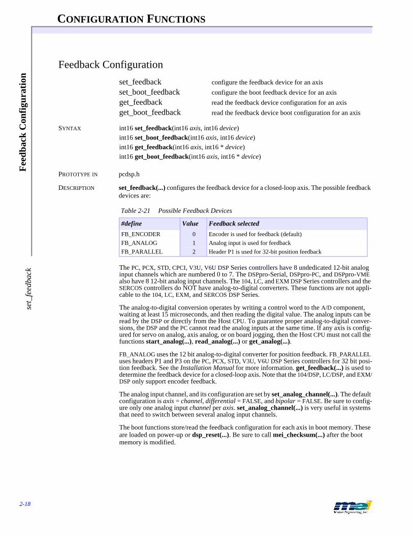
CONFIGURATION FUNCTIONS
2-18
Fee
dbac
k C
onfi
gura
tion
set_
feed
back
Feedback Configuration
set_feedback configure the feedback device for an axisset_boot_feedback configure the boot feedback device for an axisget_feedback read the feedback device configuration for an axisget_boot_feedback read the feedback device boot configuration for an axis
SYNTAX int16 set_feedback(int16 axis, int16 device)int16 set_boot_feedback(int16 axis, int16 device)int16 get_feedback(int16 axis, int16 * device)int16 get_boot_feedback(int16 axis, int16 * device)
PROTOTYPE IN pcdsp.h
DESCRIPTION set_feedback(...) configures the feedback device for a closed-loop axis. The possible feedback devices are:
The PC, PCX, STD, CPCI, V3U, V6U DSP Series controllers have 8 undedicated 12-bit analog input channels which are numbered 0 to 7. The DSPpro-Serial, DSPpro-PC, and DSPpro-VME also have 8 12-bit analog input channels. The 104, LC, and EXM DSP Series controllers and the SERCOS controllers do NOT have analog-to-digital converters. These functions are not appli-cable to the 104, LC, EXM, and SERCOS DSP Series.
The analog-to-digital conversion operates by writing a control word to the A/D component, waiting at least 15 microseconds, and then reading the digital value. The analog inputs can be read by the DSP or directly from the Host CPU. To guarantee proper analog-to-digital conver-sions, the DSP and the PC cannot read the analog inputs at the same time. If any axis is config-ured for servo on analog, axis analog, or on board jogging, then the Host CPU must not call the functions start_analog(...), read_analog(...) or get_analog(...).
FB_ANALOG uses the 12 bit analog-to-digital converter for position feedback. FB_PARALLEL uses headers P1 and P3 on the PC, PCX, STD, V3U, V6U DSP Series controllers for 32 bit posi-tion feedback. See the Installation Manual for more information. get_feedback(...) is used to determine the feedback device for a closed-loop axis. Note that the 104/DSP, LC/DSP, and EXM/DSP only support encoder feedback.
The analog input channel, and its configuration are set by set_analog_channel(...). The default configuration is axis = channel, differential = FALSE, and bipolar = FALSE. Be sure to config-ure only one analog input channel per axis. set_analog_channel(...) is very useful in systems that need to switch between several analog input channels.
The boot functions store/read the feedback configuration for each axis in boot memory. These are loaded on power-up or dsp_reset(...). Be sure to call mei_checksum(...) after the boot memory is modified.
Table 2-21 Possible Feedback Devices
#define Value Feedback selected
FB_ENCODER 0 Encoder is used for feedback (default)FB_ANALOG 1 Analog input is used for feedbackFB_PARALLEL 2 Header P1 is used for 32-bit position feedback

CONFIGURATION FUNCTIONS
2-19
Feedback C
onfiguration set_feedback
RETURN VALUES
SEE ALSO set_analog_channel(...), get_axis_analog(...)
SAMPLE CODE This sample code checks if axis 0 has an encoder for its feedback device.
# include <stdio.h># include "pcdsp.h"
int main(){
int16 device;
if (dsp_init(PCDSP_BASE)) /* any problems initializing? */return dsp_error; /* just terminate the program. */
get_feedback(0, &device);if (device == FB_ENCODER)
printf("Axis 0 uses an encoder for position feedback\n");
return dsp_error ; /* global variable provided by the library */}
Returnsset_feedback(...)set_boot_feedback(...)get_feedback(...)get_boot_feedback(...)
Error return codes (see Error Handling on page 3-13)

CONFIGURATION FUNCTIONS
2-20
Dua
l Loo
p C
onfi
gura
tion
set_
dual
_loo
p
Dual Loop Configuration
set_dual_loop configure an axis for dual loop operationset_boot_dual_loop configure an axis for dual loop operation at bootget_dual_loop read if an axis is configured for dual loop operationget_boot_dual_loop read if an axis is configured for boot dual loop operation
SYNTAX int16 set_dual_loop(int16 axis, int16 velocity_axis, int16 dual)int16 set_boot_dual_loop(int16 axis, int16 velocity_axis, int16 dual)int16 get_dual_loop(int16 axis, int16 * velocity_axis, int16 * dual)int16 get_boot_dual_loop(int16 axis, int16 * velocity_axis, int16 * dual)
PROTOTYPE IN pcdsp.h
DESCRIPTION set_dual_loop(...) configures an axis for either dual loop feedback control (dual = TRUE) or single loop feedback control (dual = FALSE). When a motor is configured for dual loop, the position information is taken from the position_axis encoder (usually connected to the load) and the velocity information is taken from the velocity_axis encoder (usually mounted to the motor). The dual loop PID algorithm uses the position_axis encoder for the proportional and integral terms, and the velocity_axis encoder (motor) for the derivative term. After an axis is configured for dual loop feedback, all motion and PID filter parameters should be commanded to the position axis. The position axis’ control output (+/-10 volts or STEP and DIR) should be connected to the motor. The velocity axis’ control output (+/-10 volts or STEP and DIR) is not used by the DSP.
get_dual_loop(...) reads the dual loop configuration.When configuring the velocity_axis for dual-loop control we are really just creating a velocity based encoder. Be sure not to mix a dual-loop velocity_axis with a cammed master_axis.
The boot functions store/read the feedback configuration for each axis in boot memory. These are loaded on power-up or dsp_reset(...). Be sure to call mei_checksum(...) after the boot memory is modified.
RETURN VALUES
Returnsset_dual_loop(...)set_boot_dual_loop(...)get_dual_loop(...)get_boot_dual_loop(...)
Error return codes (see Error Handling on page 3-13)
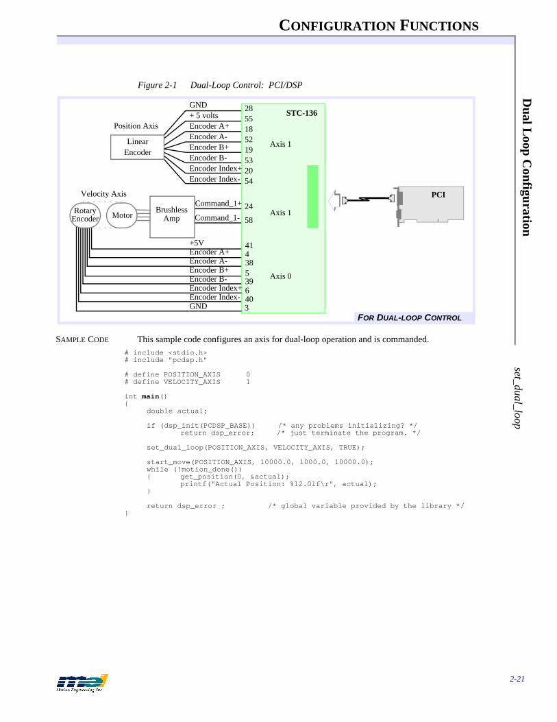
CONFIGURATION FUNCTIONS
2-21
Dual L
oop Configuration
set_dual_loop
Figure 2-1 Dual-Loop Control: PCI/DSP
SAMPLE CODE This sample code configures an axis for dual-loop operation and is commanded.# include <stdio.h># include "pcdsp.h"
# define POSITION_AXIS 0# define VELOCITY_AXIS 1
int main(){
double actual;
if (dsp_init(PCDSP_BASE)) /* any problems initializing? */return dsp_error; /* just terminate the program. */
set_dual_loop(POSITION_AXIS, VELOCITY_AXIS, TRUE);
start_move(POSITION_AXIS, 10000.0, 1000.0, 10000.0);while (!motion_done()){ get_position(0, &actual);
printf("Actual Position: %12.0lf\r", actual);}
return dsp_error ; /* global variable provided by the library */}
LinearEncoder
BrushlessAmp
GND+ 5 voltsEncoder A+Encoder A-Encoder B+Encoder B-Encoder Index+Encoder Index-
+5V
Encoder A-
Encoder Index-
Encoder B+Encoder B-Encoder Index+
28
1855
1952
532054
24
58
438539640
FOR DUAL-LOOP CONTROL
Axis 1
Motor
3
41
GND
Encoder A+
Axis 0
PCI
STC-136
Command_1+
Command_1- Axis 1
Velocity Axis
RotaryEncoder
Position Axis

CONFIGURATION FUNCTIONS
2-22
Enc
oder
Int
egri
ty C
heck
ing
set_
feed
back
_che
ck
Encoder Integrity Checking
set_feedback_check enable/disable encoder feedback fault detectionget_feedback_check read feedback fault detection configuration
SYNTAX int16 set_feedback_check(int16 axis, int16 state)int16 get_feedback_check(int16 axis, int16 * state)
PROTOTYPE IN pcdsp.h
ENCODER SAFETY The latest DSP-Series hardware, firmware, and software revisions support the following en-coder safety features:
• Broken Wire Detection (requires differential encoder)• Illegal State Detection (requires differential encoder)• Encoder Input State Filtering.
The following hardware revisions (or higher) are required to support these:
Older hardware revisions cannot be upgraded to support the new encoder safety features.
DESCRIPTION Use set_feedback_check(…) to control broken encoder wire and illegal state detection: en-abled (state = TRUE) or disabled (state = FALSE) . Use get_feedback_check(…) to read the current axis’ feedback checking configuration. When feedback checking is enabled, the DSP will examine the broken wire and illegal state registers every sample. If the DSP detects an en-coder failure, an Abort Event will be generated on the appropriate axis.The encoder inputs (channel A+, A-, B+, B-) are monitored by the FPGA (an on-board logic component). The encoder inputs are sampled at 10 MHz. A 4-state digital filter has been added to each of the encoder inputs position counters in the FPGA. This filter requires that an encoder input (channel A+, A-, B+, B-) be stable for 4 clock cycles (400 nanoseconds) before a transi-tion is recognized.
A broken encoder wire condition occurs when either A+ or A- channels or B+ and B- channels are in the same logic state for 3 consecutive sample periods (300 nsec). When a broken encoder wire is detected, broken wire generates an ABORT_EVENT and returns a source of ID_FEEDBACK_FAULT. Broken wire detection is not applicable to single ended encoders.
An Illegal State condition occurs when the A and B encoders both change state between two consecutive samples. When an error condition is detected, Illegal State Detection generates an ABORT_EVENT and returns a source of ID_FEEDBACK_ILLEGAL_STATE.
axis_source(...) can be used to determine the cause of the Exception Event. Two new identi-
Controller RevPCX/DSP 3STD/DSP 8104/DSP 6104X/DSP 1LC/DSP 8V6U/DSP 3PCI/DSP 1CPCI/DSP 1
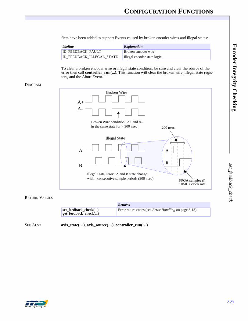
CONFIGURATION FUNCTIONS
2-23
Encoder Integrity C
hecking set_feedback_check
fiers have been added to support Events caused by broken encoder wires and illegal states:
To clear a broken encoder wire or illegal state condition, be sure and clear the source of the error then call controller_run(...). This function will clear the broken wire, illegal state regis-ters, and the Abort Event.
DIAGRAM
RETURN VALUES
SEE ALSO axis_state(…), axis_source(…), controller_run(…)
#define ExplanationID_FEEDBACK_FAULT Broken encoder wireID_FEEDBACK_ILLEGAL_STATE Illegal encoder state logic
Returnsset_feedback_check(...)get_feedback_check(...)
Error return codes (see Error Handling on page 3-13)
Broken Wire
A+A-
Broken Wire condition: A+ and A- in the same state for > 300 nsec
Illegal State
Illegal State Error: A and B state change within consecutive sample periods (200 nsec)
A
B
200 nsec
A
B
FPGA samples @ 10MHz clock rate

CONFIGURATION FUNCTIONS
2-24
Step
Out
put C
onfi
gura
tion
dsp_
step
per
Step Output Configuration
dsp_stepper returns TRUE if an axis’ step output is enableddsp_boot_stepper returns TRUE if an axis’ step output is enabled at bootdsp_set_stepper enable/disable an axis’ step outputdsp_set_boot_stepper enable/disable an axis’ boot step outputdsp_step_config reads step mode configurationdsp_boot_step_config returns boot step mode configurationdsp_set_step_config sets the step mode configurationdsp_set_boot_step_config sets the boot step mode configuration
SYNTAX int16 dsp_stepper(int16 axis)int16 dsp_boot_stepper(int16 axis)int16 dsp_set_stepper(int16 axis, int16 stepper)int16 dsp_set_boot_stepper(int16 axis, int16 stepper)int16 dsp_step_config(int16 axis, int16 *mode)int16 dsp_boot_step_config(int16 axis)int16 dsp_set_step_config(int16 axis, int 16 mode)int16 dsp_set_boot_step_config(int16 axis, int16 mode)
PROTOTYPE IN pcdsp.h
DESCRIPTION dsp_set_stepper(...) configures an axis for use with a step motor. The STEP and DIR output are enabled when stepper = TRUE and disabled when stepper = FALSE. This affects pairs of axes (0 and 1, 2 and 3 etc.). Don't forget to change the digital filter tuning parameters when switch-ing from servo to step motors. dsp_stepper(...) returns TRUE if an axis is configured for step-per operation.The function dsp_step_config(...) reads the current step mode configuration from the DSP controller. The function dsp_set_step_config(...) sets the step mode configuration . The boot mode configuration can be written with dsp_set_boot_step_config(..) and read with the func-tion dsp_boot_step_config(..). These functions require that the 1.33/2.33 PROM chipset be installed on the DSP Series controller with 2.4G2 firmware or greater. The supported values for mode are:
The boot functions store/read the stepper configuration for each axis in boot memory. These are loaded on power-up or dsp_reset(...). Be sure to call mei_checksum(...) after the boot memory is modified.
RETURN VALUES
# define STEPDIR 0 for step and direction# define CWCCW 1 for clockwise/ counter clockwise
Returnsdsp_stepper(...)dsp_boot_stepper(...)dsp_boot_step_config(...)
Values
dsp_set_stepper(...)dsp_set_boot_stepper(...)dsp_step_config(...)dsp_set_step_config(...)dsp_set_boot_step_config(...)
Error return codes (see Error Handling on page 3-13)

CONFIGURATION FUNCTIONS
2-25
Step Output C
onfiguration dsp_stepper
SAMPLE CODE This sample code checks if the step output is enabled for axis 0.
# include <stdio.h># include "pcdsp.h"
int main(){
if (dsp_init(PCDSP_BASE)) /* any problems initializing? */return dsp_error; /* just terminate the program. */
if (dsp_stepper(0))printf(“Axis 0’s step ouptut is enabled\n”);
elseprintf(“Axis 0’s step output is disabled\n”);
return dsp_error ; /* global variable provided by the library */}

CONFIGURATION FUNCTIONS
2-26
Step
Out
put S
peed
Ran
geds
p_st
ep_s
peed
Step Output Speed Range
dsp_step_speed Read an axis’ step output speed rangedsp_boot_step_speed Read an axis’ boot step output speed rangedsp_set_step_speed Configure an axis’ step output speed rangedsp_set_boot_step_speed Configure an axis’ boot step output speed range
SYNTAX int16 dsp_step_speed(int16 axis, int16 * speed)int16 dsp_boot_step_speed(int16 axis, int16 * speed)int16 dsp_set_step_speed(int16 axis, int16 speed)int16 dsp_set_boot_step_speed(int16 axis, int16 speed)
PROTOTYPE IN pcdsp.h
DESCRIPTION Use dsp_set_step_speed(...) to configure the step speed range of an axis.
The speed range sets the maximum pulse rate output. The lower the speed range, the higher the resolution, and the better the step motor will perform. Slow is most frequently used. The only limitation of the Slow setting is the maximum velocity. Using the Slow setting has no effect on the maximum acceleration or the maximum jerk.
A new step output speed, R550KHZ_STEP_OUTPUT, has been added to accomodate appli-cations that require higher step rates. This feature requires that the 1.33/2.33 PROM chipset be installed on the DSP Series controller and firmware version 2.4G2 or greater.
The step output speeds have also been renamed to reflect the actual tested limits for each range. For version compatibility, the old #defines will work with the new libraries.
dsp_step_speed(...) reads an axis’ speed range configuration.
Table 2-22 Step Pulse Output
#define Value Old #defines
DISABLE_STEP_OUTPUT 0 DISABLE_STEP_OUTPUTR17KHZ_STEP_OUTPUT 3 SLOW_STEP_OUTPUTR70KHZ_STEP_OUTPUT 2 MEDIUM_STEP_OUTPUTR275KHZ_STEP_OUTPUT 1 FAST_STEP_OUTPUTR550KHZ_STEP_OUTPUT 4 Not Applicable
Table 2-23 Step Speed Ranges
Controller Slow Medium Fast Superfast
PC/DSP 0 to 125 kHz 0 to 500 kHz 0 to 2.0 MHz N/APCX/DSP 0 to 17 kHz 0 to 70 kHz 0 to 275 kHz 0 to 550 kHzSTD/DSP 0 to 17 kHz 0 to 70 kHz 0 to 275 kHz 0 to 550 kHz104/DSP 0 to 17 kHz 0 to 70 kHz 0 to 275 kHz 0 to 550 kHzLC/DSP 0 to 17 kHz 0 to 70 kHz 0 to 275 kHz 0 to 550 kHzV6U/DSP 0 to 17 kHz 0 to 70 kHz 0 to 275 kHz 0 to 550 kHz104X/DSP 0 to 17 kHz 0 to 70 kHz 0 to 275 kHz 0 to 550 kHzCPCI/DSP 0 to 17 kHz 0 to 70 kHz 0 to 275 kHz 0 to 550 kHzPCI/DSP 0 to 17 kHz 0 to 70 kHz 0 to 275 kHz 0 to 550 kHzDSPpro-Serial 0 to 17 kHz 0 to 70 kHz 0 to 275 kHz 0 to 550 kHzDSPpro-VME 0 to 17 kHz 0 to 70 kHz 0 to 275 kHz 0 to 550 kHz

CONFIGURATION FUNCTIONS
2-27
Step Output Speed R
ange dsp_step_speed
The boot functions store/read the step speed configuration for each axis in boot memory. These are loaded on power-up or dsp_reset(...). Be sure to call mei_checksum(...) after the boot memory is modified.
RETURN VALUES
SAMPLE CODE This sample code enables the STEP and DIR outputs for axis 0 using the slow speed range.
# include <stdio.h># include "pcdsp.h"
int main(){
if (dsp_init(PCDSP_BASE)) /* any problems initializing? */return dsp_error; /* just terminate the program. */
set_unipolar(0, TRUE); /* enable direction output bit */dsp_set_stepper(0, TRUE); /* enable step-pulse output */dsp_set_step_speed(0, R17KHZ_STEP_OUTPUT); /* slow speed range */
return dsp_error ; /* global variable provided by the library */}
Returnsdsp_step_speed(...)dsp_boot_step_speed(...)dsp_set_step_speed(...)dsp_set_boot_step_speed(...)
Error return codes (see Error Handling on page 3-13)
CONFIGURATION FUNCTIONS
2-28
Ana
log
Out
put V
olta
ge C
onfi
gura
tion
is_u
nipo
lar
Analog Output Voltage Configuration
is_unipolar returns TRUE if an axis’ analog output is unipolaris_boot_unipolar returns TRUE if an axis’ analog output is unipolar at bootset_unipolar configure an axis’ analog outputset_boot_unipolar configure an axis’ boot analog output
SYNTAX int16 is_unipolar(int16 axis)int16 is_boot_unipolar(int16 axis)int16 set_unipolar(int16 axis, int16 state)int16 set_boot_unipolar(int16 axis, int16 state)
PROTOTYPE IN pcdsp.h
DESCRIPTION set_unipolar(...) configures an axis’ analog output voltage for either unipolar (state = TRUE) or bipolar (state = FALSE) operation. If an axis is configured for bipolar operation, the analog output voltage range will be from -10 volts to +10 volts. The sign of the voltage indicates either the positive or negative direction.
If an axis is configured for unipolar operation, the analog output voltage range will be from 0 volts to +10 volts. The direction output bit will indicate positive or negative direction. Unipolar is the correct configuration for step motors. If a step motor axis is configured for bipolar oper-ation, it will only go in one direction.
The boot functions store/read the unipolar configuration for each axis in boot memory. These are loaded on power-up or dsp_reset(...). Be sure to call mei_checksum(...) after the boot memory is modified.
RETURN VALUES
SAMPLE CODE This sample code checks if axis 0 is configured for unipolar operation.
# include <stdio.h># include "pcdsp.h"
int main(){
if (dsp_init(PCDSP_BASE)) /* any problems initializing? */return dsp_error; /* just terminate the program. */
if (is_unipolar(0))printf("Analog output is configured for 0 to 10 volts\n");
elseprintf("Analog output is configured for +/- 10 volts\n");
return dsp_error ; /* global variable provided by the library */}
Returnsis_unipolar(...)is_boot_unipolar(...)
Values
set_unipolar(...)set_boot_unipolar(...)
Error return codes (see Error Handling on page 3-13)

CONFIGURATION FUNCTIONS
2-29
PID
Filter P
arameters
set_filter
PID Filter Parameters
set_filter set the PID filter coefficientsset_boot_filter set the boot PID filter coefficientsget_filter get the PID filter coefficientsget_boot_filter get the boot PID filter coefficientsset_integration set the integration modeset_boot_integration set the boot integration modeget_integration get the integration modeget_boot_integration get the boot integration mode
SYNTAX int16 set_filter(int16 axis, int16 * coeffs)int16 set_boot_filter(int16 axis, int16 * coeffs)int16 get_filter(int16 axis, int16 * coeffs)int16 get_boot_filter(int16 axis, int16 * coeffs)
int16 set_integration(int16 axis, int16 mode)int16 set_boot_integration(int16 axis, int16 mode)int16 get_integration(int16 axis, int16 * mode)int16 get_boot_integration(int16 axis, int16 * mode)
PROTOTYPE IN pcdsp.h
DESCRIPTION set_filter(...) configures an axis’ filter coefficients. get_filter(...) reads the current filter coef-ficients used by the DSP controller. Both functions expect a pointer to an array of integers, mapped as follows:
The integration mode for an axis is set by calling set_integration(...) with mode:
Table 2-24 PID Filter Parameters
#define Value Explanation
DF_P 0 Proportional gainDF_I 1 Integral gainDF_D 2 Derivative gain - damping termDF_ACCEL_FF 3 Acceleration feed forwardDF_VEL_FF 4 Velocity feed-forwardDF_I_LIMIT 5 Integration summing limitDF_OFFSET 6 Voltage output offsetDF_DAC_LIMIT 7 Voltage output limitDF_SHIFT 8 2^(n) divisorDF_FRICT_FF 9 Friction Feed ForwardCOEFFICIENTS 10 Number of elements
Table 2-25 Integration Active/Not Active
#define Value Explanation
IM_STANDING 0 Integration active only when command velocity is zeroIM_ALWAYS 1 Integration is always active
CONFIGURATION FUNCTIONS
2-30
PID
Filt
er P
aram
eter
sse
t_fil
ter
The boot functions store/read the digital filter coefficients for each axis in boot memory. These are loaded on power-up or dsp_reset(...). Make sure to call mei_checksum(...) after the boot memory is modified.
RETURN VALUES
SEE ALSO dsp_set_filter(...)
SAMPLE CODE The following code decreases the gain before a first move, and increases it before a second move:
# include <stdio.h># include "pcdsp.h"
int main(){
int16 Coefficients[COEFFICIENTS];
if (dsp_init(PCDSP_BASE)) /* any problems initializing? */return dsp_error; /* just terminate the program. */
get_filter(0, Coefficients);Coefficients[DF_P] = 512; /* low proportional gain */set_filter(0, Coefficients); /* set the filter parameters */move(0, 100000., 8000., 16000.);
Coefficients[DF_P] = 1024; /* high proportional gain */set_filter(0, Coefficients); /* set the filter parameters */move(0, 0., 8000., 16000.);
return dsp_error ; /* global variable provided by the library */}
NOTES Sometimes it is difficult to find a set of tuning parameters that will produce accurate motion without oscillation (usually due to poor mechanical systems with servo motors). Thus, it may be necessary to have 2 sets of tuning parameters.
One set of parameters with a low gain might be used when the motor is not in motion and an-other set of tuning parameters with a higher gain could be used during motion. See the Instal-lation Manual for helpful hints on finding correct filter parameters.
Returnsset_filter(...)set_boot_filter(...)get_filter(...)get_boot_filter(...)set_integration(...)set_boot_integration(...)get_integration(...)get_boot_integration(...)
Error return codes (see Error Handling on page 3-13)
CONFIGURATION FUNCTIONS
2-31
Auxiliary F
ilter Param
eters set_aux_filter
Auxiliary Filter Parameters
set_aux_filter set the auxiliary digital filter coefficientsset_boot_aux_filter set the boot auxiliary digital filter coefficientsget_aux_filter get the auxiliary digital filter coefficientsget_boot_aux_filter get the boot auxiliary digital filter coefficients
SYNTAX int16 set_aux_filter(int16 axis, int16 * coeffs)int16 set_boot_aux_filter(int16 axis, int16 * coeffs)int16 get_aux_filter(int16 axis, int16 * coeffs)int16 get_boot_aux_filter(int16 axis, int16 * coeffs)
PROTOTYPE IN pcdsp.h
DESCRIPTION set_aux_filter(...) configures an axis’ auxiliary filter coefficients. get_aux_filter(...) reads the current auxiliary filter coefficients used by the DSP controller. Both functions expect a pointer to an array of integers.
Currently, only the first auxiliary digital filter coefficient is supported. The derivative term of the PID algorithm can be calculated at slower sample rates than the other terms. The lower 8 bits of the first auxiliary filter coefficient (B0) control the derivative sample rate:
The first auxiliary coefficient (B0) should be equal to (2^n) -1 where 2^n is the DSP sample rate divisor. Using (2n)-1 will guarantee a uniform derivative sample rate. Systems with very high rotational inertia will benefit from a derivative term with a lower sample rate. As the de-rivative sample rate is decreased, its effectiveness increases.
The boot functions store/read the auxiliary digital filter coefficients for each axis in boot mem-ory. These are loaded on power-up or dsp_reset(...). Be sure to call mei_checksum(...) after the boot memory is modified.
RETURN VALUES
SEE ALSO set_filter(...), get_filter(...), dsp_sample_rate(...), get_sample_rate(...)
Table 2-26 First Auxiliary Coefficient
#define Value Explanation
AUX_FILTER_COEFFS 10 Number of elements
Table 2-27 Derivative Sample Rate
B0 Derivative Sample Rate
0 DSP Sample Rate1 DSP Sample Rate / 23 DSP Sample Rate / 47 DSP Sample Rate / 815 DSP Sample Rate / 1631 DSP Sample Rate / 32
Returnsset_aux_filter(...), set_boot_aux_filter(...)get_aux_filter(...), get_boot_aux_filter(...)
Error return codes (see Error Handling on page 3-13)
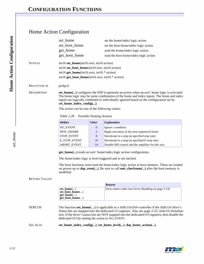
CONFIGURATION FUNCTIONS
2-32
Hom
e A
ctio
n C
onfi
gura
tion
set_
hom
e
Home Action Configuration
set_home set the home/index logic actionset_boot_home set the boot home/index logic actionget_home read the home/index logic actionget_boot_home read the boot home/index logic action
SYNTAX int16 set_home(int16 axis, int16 action)int16 set_boot_home(int16 axis, int16 action)int16 get_home(int16 axis, int16 * action)int16 get_boot_home(int16 axis, int16 * action)
PROTOTYPE IN pcdsp.h
DESCRIPTION set_home(...) configures the DSP to generate an action when an axis’ home logic is activated. The home logic may be some combination of the home and index inputs. The home and index inputs are logically combined or individually ignored based on the configuration set by set_home_index_config(...).
The action can be one of the following values:
get_home(...) reads an axis’ home/index logic action configuration.
The home/index logic is level triggered and is not latched.
The boot functions store/read the home/index logic action in boot memory. These are loaded on power-up or dsp_reset(...). Be sure to call mei_checksum(...) after the boot memory is modified.
RETURN VALUES
SERCOS The function set_home(…) is applicable to a SERCOS/DSP-controller if the SERCOS drive’s Status bits are mapped into the dedicated I/O registers. Also see page 2-53, SERCOS Initializa-tion. If the drive’s status bits are NOT mapped into the dedicated I/O registers, then disable the dedicated I/O by setting the action to NO_EVENT.
SEE ALSO set_home_index_config(...), set_home_level(...), dsp_home_action(...)
Table 2-28 Possible Homing Actions
#define Value Explanation
NO_EVENT 0 Ignore a conditionNEW_FRAME 2 Begin execution of the next sequenced frameSTOP_EVENT 8 Decelerate to a stop (at specified stop rate)E_STOP_EVENT 10 Decelerate to a stop (at specified E-stop rate)ABORT_EVENT 14 Disable PID control and the amplifier for this axis
Returnsset_home(...)set_boot_home(...)get_home(...)get_boot_home(...)
Error return codes (see Error Handling on page 3-13)

CONFIGURATION FUNCTIONS
2-33
Hom
e Action C
onfiguration set_hom
e
SAMPLE CODE This code configures the DSP to generate a STOP_EVENT when the home signal goes low.
# include <stdio.h># include "pcdsp.h"
int main(){
if (dsp_init(PCDSP_BASE)) /* any problems initializing? */return dsp_error; /* just terminate the program. */
/* configure the home logic for home input only */set_home_index_config(0, HOME_ONLY);set_home_level(0, FALSE); /* configure for active low logic */set_home(0, STOP_EVENT); /* configure for a Stop Event */
return dsp_error ; /* global variable provided by the library */}

CONFIGURATION FUNCTIONS
2-34
Hom
e L
ogic
Con
figu
rati
onse
t_ho
me_
inde
x_co
nfig
Home Logic Configuration
set_home_index_config configure the home/index logicset_boot_home_index_config configure the boot home/index logicget_home_index_config read the home/index logic configurationget_boot_home_index_config read the boot home/index logic configurationset_home_level configure the active state of the home/index logicset_boot_home_level configure the boot active state of the home/index logicget_home_level read the active state of the home/index logic configurationget_boot_home_level read the boot active home state of the home/index logic con-
figuration
SYNTAX int16 set_home_index_config(int16 axis, int16 config)int16 set_boot_home_index_config(int16 axis, int16 config)int16 get_home_index_config(int16 axis, int16 * config)int16 get_boot_home_index_config(int16 axis, int16 * config)
int16 set_home_level(int16 axis, int16 level)int16 set_boot_home_level(int16 axis, int16 level)int16 get_home_level(int16 axis, int16 * level)int16 get_boot_home_level(int16 axis, int16 * level)
PROTOTYPE IN pcdsp.h
DESCRIPTION set_home_index_config(...) configures the home/index logicEach axis has a dedicated home and index input. The home and index inputs are logically com-bined or individually ignored based on the configuration. The home/index configuration af-fects axes in groups of four (0 to 3, or 4 to 7).
These configurations require version 1.21, 2.21 (or later) EPROMs for the surface mount con-trollers or Home 1D and Home 2D (or later) GALs for the PC/DSP.
Each sample the DSP examines the home logic to decide if an exception event should be gen-erated. To guarantee that the DSP does not miss the home logic the home input and/or index pulse must be longer than one DSP sample. The default sample rate is 1250 samples/sec. set_home_level(...) configures an axis’ home logic for either active low (level = FALSE) or ac-tive high (level = TRUE) operation.
Table 2-29 Home Index Configurations
#define Value Explanation
HOME_ONLY 0 home input only (active high or active low)LOW_HOME_AND_INDEX 1 home input ANDed with index (active low home and
active high index)INDEX_ONLY 2 index only (active high or active low)HIGH_HOME_AND_INDEX 3 home input ANDed with index (active high home and
active high index)

CONFIGURATION FUNCTIONS
2-35
Hom
e Logic C
onfiguration set_hom
e_index_config
Figure 2-2 Motion Status During Trapezoidal Profile Move
The following table shows all of the possible home logic configurations. An Event is generated when the home logic reaches the active state. A value of 0 indicates a low signal (0 volts) and a value of 1 indicates a high signal (+5 volts). True indicates an exception event is generated and False means no exception event is generated.
Home/index logic configurations 1 and 3 invert the combined logic of the home and index sig-nals (for backwards compatibility). In most applications, when home/index configuration 1 or 3 is used the home/index level should be set to active low (FALSE).
get_home_index_config(...) reads the home/index logic configuration. get_home_level(...) reads the active state configuration of the home/index logic.
The boot functions store/read the home/index configurations in boot memory. These are loaded on power-up or dsp_reset(...). Be sure to call mei_checksum(...) after the boot memory is modified.
Table 2-30 Possible Home Logic Configurations
Config Home Index Event Active Low
Event Active High
0 0 0 True False0 0 1 True False0 1 0 False True0 1 1 False True1 0 0 False True1 0 1 True False1 1 0 False True1 1 1 False True2 0 0 True False2 0 1 False True2 1 0 True False2 1 1 False True3 0 0 False True3 0 1 False True3 1 0 False True3 1 1 True False
HOME/INDEXLOGIC
Home Input
Index InputDSPHome State

CONFIGURATION FUNCTIONS
2-36
Hom
e L
ogic
Con
figu
rati
onse
t_ho
me_
inde
x_co
nfig
RETURN VALUES
SERCOS The functions set_home_level(…), get_home_level(…), set_boot_home_level(…), and get_boot_home_level(…) are applicable to a SERCOS/DSP Series controller if the SERCOS drive’s Status bits are mapped into the dedicated I/O registers. Also see page 2-53, SERCOS Ini-tialization. If the drive’s Status bits are NOT mapped into the dedicated I/O registers, then dis-able the dedicated I/O by setting the action to NO_EVENT.
SEE ALSO set_home(...), dsp_home_action(...), home_switch(...)
SAMPLE CODE This code configures the DSP to generate a STOP_EVENT when the home signal is low and the index is high.
# include <stdio.h># include "pcdsp.h"
int main(){
if (dsp_init(PCDSP_BASE)) /* any problems initializing? */return dsp_error; /* just terminate the program. */
/* configure the home logic for home & index */set_home_index_config(0, LOW_HOME_AND_INDEX);set_home_level(0, FALSE); /* configure for active low logic*/set_home(0, STOP_EVENT); /* configure for a Stop Event */
return dsp_error ; /* global variable provided by the library */}
NOTES Almost every application requires a homing routine. The programmer needs to decide how to home the axes based on the mechanics of the system. Very often, the homing routine is the most complicated task in an application. Be sure to examine the Applications distribution disk. It contains several sample homing routines.
Returnsset_home_index_config(...)set_boot_home_index_config(...)get_home_index_config(...)get_boot_home_index_config(...)set_home_level(...)set_boot_home_level(...)get_home_level(...)get_boot_home_level(...)
Error return codes (see Error Handling on page 3-13)

CONFIGURATION FUNCTIONS
2-37
Lim
it Input Action C
onfiguration set_positive_lim
it
Limit Input Action Configuration
set_positive_limit set an axis’ positive limit input actionset_boot_positive_limit set an axis’ boot positive limit input actionget_positive_limit read an axis’ positive limit input actionget_boot_positive_limit read an axis’ boot positive limit input actionset_negative_limit set an axis’ negative limit input actionset_boot_negative_limit set an axis’ boot negative limit input actionget_negative_limit read an axis’ negative limit input actionget_boot_negative_limit read an axis’ boot negative limit input action
SYNTAX set_positive_limit(int16 axis, int16 action)set_boot_positive_limit(int16 axis, int16 action)get_positive_limit(int16 axis, int16 * action)get_boot_positive_limit(int16 axis, int16 * action)
set_negative_limit(int16 axis, int16 action)set_boot_negative_limit(int16 axis, int16 action)get_negative_limit(int16 axis, int16 * action)get_boot_negative_limit(int16 axis, int16 * action)
PROTOTYPE IN pcdsp.h
DESCRIPTION set_positive_limit(...), set_negative_limit(...) configure the DSP to generate an action when an axis’ positive, negative limit input is activated. The action can be one of the following:
get_positive_limit(...), get_negative_limit(...) read an axis’ limit input action configuration.
The boot functions store/read the limit configurations for each axis in boot memory. These are loaded on power-up or dsp_reset(...). Be sure to call mei_checksum(...) after the boot memory is modified.
RETURN VALUES
Table 2-31 Possible DSP-Generated Actions
#define Value Explanation
NO_EVENT 0 Ignore a conditionNEW_FRAME 2 Begin execution of the next sequenced frameSTOP_EVENT 8 Decelerate to a stop (at specified stop rate)E_STOP_EVENT 10 Decelerate to a stop (at specified E-stop rate)ABORT_EVENT 14 Disable PID control and the amplifier for this axis
Returnsset_positive_limit(...)set_boot_positive_limit(...)get_positive_limit(...)get_boot_positive_limit(...)set_negative_limit(...)set_boot_negative_limit(...)get_negative_limit(...)get_boot_negative_limit(...)
Error return codes (see Error Handling on page 3-13)
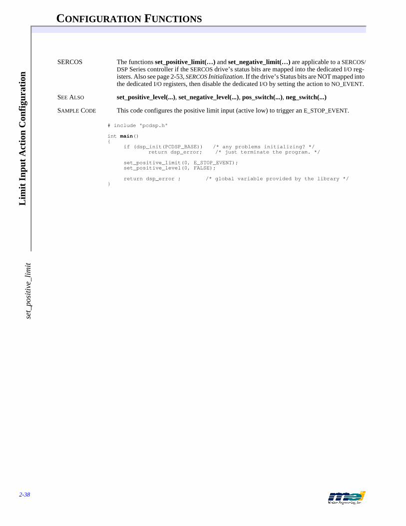
CONFIGURATION FUNCTIONS
2-38
Lim
it I
nput
Act
ion
Con
figu
rati
onse
t_po
sitiv
e_lim
it
SERCOS The functions set_positive_limit(…) and set_negative_limit(…) are applicable to a SERCOS/DSP Series controller if the SERCOS drive’s status bits are mapped into the dedicated I/O reg-isters. Also see page 2-53, SERCOS Initialization. If the drive’s Status bits are NOT mapped into the dedicated I/O registers, then disable the dedicated I/O by setting the action to NO_EVENT.
SEE ALSO set_positive_level(...), set_negative_level(...), pos_switch(...), neg_switch(...)
SAMPLE CODE This code configures the positive limit input (active low) to trigger an E_STOP_EVENT.
# include "pcdsp.h"
int main(){
if (dsp_init(PCDSP_BASE)) /* any problems initializing? */return dsp_error; /* just terminate the program. */
set_positive_limit(0, E_STOP_EVENT);set_positive_level(0, FALSE);
return dsp_error ; /* global variable provided by the library */}
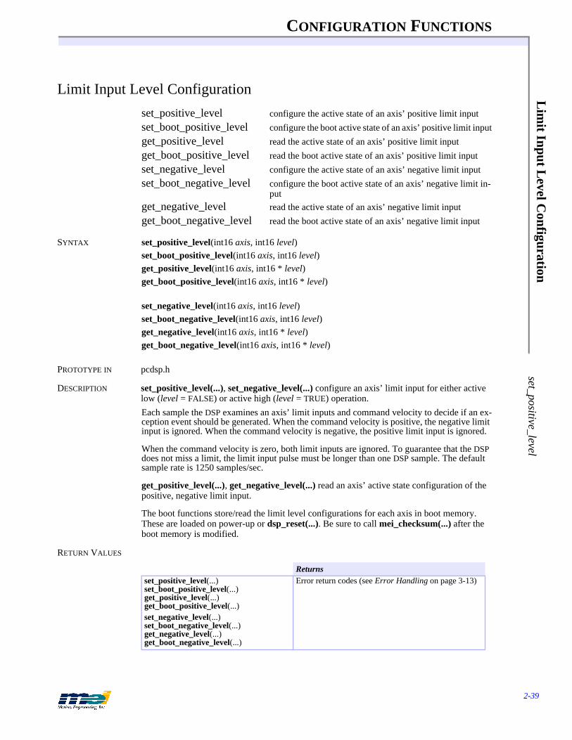
CONFIGURATION FUNCTIONS
2-39
Lim
it Input Level C
onfiguration set_positive_level
Limit Input Level Configuration
set_positive_level configure the active state of an axis’ positive limit inputset_boot_positive_level configure the boot active state of an axis’ positive limit inputget_positive_level read the active state of an axis’ positive limit inputget_boot_positive_level read the boot active state of an axis’ positive limit inputset_negative_level configure the active state of an axis’ negative limit inputset_boot_negative_level configure the boot active state of an axis’ negative limit in-
putget_negative_level read the active state of an axis’ negative limit inputget_boot_negative_level read the boot active state of an axis’ negative limit input
SYNTAX set_positive_level(int16 axis, int16 level)set_boot_positive_level(int16 axis, int16 level)get_positive_level(int16 axis, int16 * level)get_boot_positive_level(int16 axis, int16 * level)
set_negative_level(int16 axis, int16 level)set_boot_negative_level(int16 axis, int16 level)get_negative_level(int16 axis, int16 * level)get_boot_negative_level(int16 axis, int16 * level)
PROTOTYPE IN pcdsp.h
DESCRIPTION set_positive_level(...), set_negative_level(...) configure an axis’ limit input for either active low (level = FALSE) or active high (level = TRUE) operation.Each sample the DSP examines an axis’ limit inputs and command velocity to decide if an ex-ception event should be generated. When the command velocity is positive, the negative limit input is ignored. When the command velocity is negative, the positive limit input is ignored.
When the command velocity is zero, both limit inputs are ignored. To guarantee that the DSP does not miss a limit, the limit input pulse must be longer than one DSP sample. The default sample rate is 1250 samples/sec.
get_positive_level(...), get_negative_level(...) read an axis’ active state configuration of the positive, negative limit input.
The boot functions store/read the limit level configurations for each axis in boot memory. These are loaded on power-up or dsp_reset(...). Be sure to call mei_checksum(...) after the boot memory is modified.
RETURN VALUES
Returnsset_positive_level(...)set_boot_positive_level(...)get_positive_level(...)get_boot_positive_level(...)set_negative_level(...)set_boot_negative_level(...)get_negative_level(...)get_boot_negative_level(...)
Error return codes (see Error Handling on page 3-13)

CONFIGURATION FUNCTIONS
2-40
Lim
it I
nput
Lev
el C
onfi
gura
tion
set_
posi
tive_
leve
l
SERCOS The functions set_positive_level(…), set_negative_level(…), set_boot_positive_level(…), set_boot_negative_level(…), get_positive_level(…), get_negative_level(…), get_boot_positive_level(…), and get_boot_negative_level(…) are applicable to a SERCOS/DSP Series controller if the SERCOS drive’s Status bits are mapped into the dedicated I/O reg-isters. Also see page 2-53, SERCOS Initialization. If the drive’s Status bits are NOT mapped into the dedicated I/O registers, then disable the dedicated I/O by setting the action to NO_EVENT.
SEE ALSO set_positive_limit(...), set_negative_limit(...), pos_switch(...), neg_switch(...)
SAMPLE CODE This code configures the positive limit input (active low) to trigger an E_STOP_EVENT.
# include "pcdsp.h"
int main(){
if (dsp_init(PCDSP_BASE)) /* any problems initializing? */return dsp_error; /* just terminate the program. */
set_positive_limit(0, E_STOP_EVENT);set_positive_level(0, FALSE);
return dsp_error ; /* global variable provided by the library */}

CONFIGURATION FUNCTIONS
2-41
Am
p Fault Input C
onfiguration set_am
p_fault
Amp Fault Input Configuration
set_amp_fault set an axis’ amp fault input actionset_boot_amp_fault set an axis’ boot amp fault input actionget_amp_fault read an axis’ amp fault input actionget_boot_amp_fault read an axis’ boot amp fault input actionset_amp_fault_level configure the active state of an axis’ amp fault inputset_boot_amp_fault_level configure the boot active state of an axis’ amp fault inputget_amp_fault_level read the active state of an axis’ amp fault inputget_boot_amp_fault_level read the boot active state of an axis’ amp fault input
SYNTAX set_amp_fault(int16 axis, int16 action)set_boot_amp_fault(int16 axis, int16 action)get_amp_fault(int16 axis, int16 * action)get_boot_amp_fault(int16 axis, int16 * action)
set_amp_fault_level(int16 axis, int16 level)set_boot_amp_fault_level(int16 axis, int16 level)get_amp_fault_level(int16 axis, int16 * level)get_boot_amp_fault_level(int16 axis, int16 * level)
PROTOTYPE IN pcdsp.h
DESCRIPTION set_amp_fault(...) configure the DSP to generate an action when an axis’ amp fault input is ac-tivated. The action can be one of the following:
set_amp_fault_level(...) configures an axis’ amp fault input for either active low (level = FALSE) or active high (level = TRUE) operation.
Each sample the DSP examines an axis’ amp fault input to decide if an exception event should be generated. To guarantee that the DSP does not miss an amp fault, the amp fault input pulse must be longer than one DSP sample. The default sample rate is 1250 samples/sec.
get_amp_fault(...) reads an axis’ amp fault action configuration. get_amp_fault_level(...) reads an axis’ active state configuration of the amp fault input.
The boot functions store/read the amp fault configurations for each axis in boot memory. These are loaded on power-up or dsp_reset(...). Be sure to call mei_checksum(...) after the boot memory is modified.
Table 2-32 Possible Axis Actions
#define Value Explanation
NO_EVENT 0 Ignore a conditionNEW_FRAME 2 Begin execution of the next sequenced frameSTOP_EVENT 8 Decelerate to a stop (at specified stop rate)E_STOP_EVENT 10 Decelerate to a stop (at specified E-stop rate)ABORT_EVENT 14 Disable PID control and the amplifier for this axis
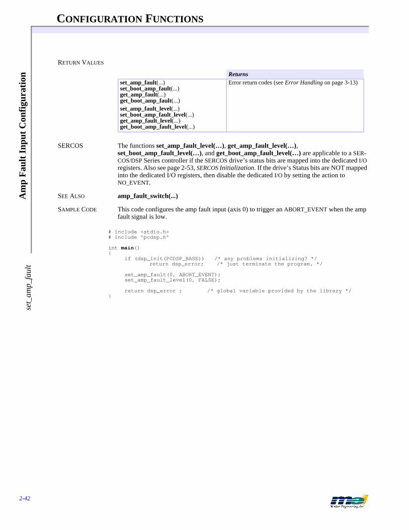
CONFIGURATION FUNCTIONS
2-42
Am
p F
ault
Inp
ut C
onfi
gura
tion
set_
amp_
faul
t
RETURN VALUES
SERCOS The functions set_amp_fault_level(…), get_amp_fault_level(…), set_boot_amp_fault_level(…), and get_boot_amp_fault_level(…) are applicable to a SER-COS/DSP Series controller if the SERCOS drive’s status bits are mapped into the dedicated I/O registers. Also see page 2-53, SERCOS Initialization. If the drive’s Status bits are NOT mapped into the dedicated I/O registers, then disable the dedicated I/O by setting the action to NO_EVENT.
SEE ALSO amp_fault_switch(...)
SAMPLE CODE This code configures the amp fault input (axis 0) to trigger an ABORT_EVENT when the amp fault signal is low.
# include <stdio.h># include "pcdsp.h"
int main(){
if (dsp_init(PCDSP_BASE)) /* any problems initializing? */return dsp_error; /* just terminate the program. */
set_amp_fault(0, ABORT_EVENT);set_amp_fault_level(0, FALSE);
return dsp_error ; /* global variable provided by the library */}
Returnsset_amp_fault(...)set_boot_amp_fault(...)get_amp_fault(...)get_boot_amp_fault(...)set_amp_fault_level(...)set_boot_amp_fault_level(...)get_amp_fault_level(...)get_boot_amp_fault_level(...)
Error return codes (see Error Handling on page 3-13)
CONFIGURATION FUNCTIONS
2-43
Am
p Enable O
utput Configuration
set_amp_enable
Amp Enable Output Configuration
set_amp_enable set the state of an axis’ amp enable outputset_boot_amp_enable set the boot state of an axis’ amp enable outputget_amp_enable read the state of an axis’ amp enable outputget_boot_amp_enable read the boot state of an axis’ amp enable outputset_amp_enable_level configure the Run state of an axis’ amp enable outputset_boot_amp_enable_level configure the boot Run state of an axis’ amp enable outputget_amp_enable_level read the Run state of an axis’ amp enable outputget_boot_amp_enable_level read the boot Run state of an axis’ amp enable output
USAGE:
SYNTAX int16 set_amp_enable(int16 axis, int16 state)int16 set_boot_amp_enable(int16 axis, int16 state)int16 get_amp_enable(int16 axis, int16 * state)int16 get_boot_amp_enable(int16 axis, int16 * state)
int16 set_amp_enable_level(int16 axis, int16 level)int16 set_boot_amp_enable_level(int16 axis, int16 level)int16 get_amp_enable_level(int16 axis, int16 * level)int16 get_boot_amp_enable_level(int16 axis, int16 * level)
PROTOTYPE IN pcdsp.h
DESCRIPTION set_amp_enable(...) tells the DSP to set an axis’ amp enable output to a high or low state. The state of the output can be TRUE (+5V) or FALSE (0V).set_amp_enable_level(...) configures an axis’ amp enable output for either active low (level = FALSE) or active high (level = TRUE) operation. The amp enable level configuration is used by the DSP and the functions enable_amplifier(...) and disable_amplifier(...).
During an Abort Event the DSP automatically disables the amp enable output. The polarity of a disabled amp enable output is determined by set_amp_enable_level(...). To re-enable the amp enable output, the Abort Event must be first be cleared with controller_run(...). Then the amp enable output can be re-enabled with set_amp_enable(...) or enable_amplifer(...).
Notice that the DSP does NOT automatically re-enable the amp enable output during a controller_run(...). This is a safety feature. The Abort Event is the DSP’s highest priority. It is the programmer’s responsibility to examine the cause of the Abort Event with axis_source(...) and determine if the problem is serious.
During normal operation, (no Abort Event) the amp enable output can be enabled or disabled with set_amp_enable(...), enable_amplifier(...) or disable_amplifer(...). The polarity of the amp enable output must be configured with set_amp_enable_level(...) before enable_amplifier(...) or disable_amplifier(...).
get_amp_enable(...) reads the state of an axis’ amp enable output. get_amp_enable_level(...) reads an axis’ active state configuration of the amp enable output.
The default boot configuration for the amp enable output is disabled.
The boot functions store/read the amp enable configurations for each axis in boot memory. These are loaded on power-up or dsp_reset(...). Be sure to call mei_checksum(...) after the boot memory is modified.
CONFIGURATION FUNCTIONS
2-44
Am
p E
nabl
e O
utpu
t Con
figu
rati
onse
t_am
p_en
able
SERCOS The functions set_amp_enable_level(…), get_amp_enable_level(…), set_boot_amp_enable_level(…), get_boot_amp_enable_level(…), set_boot_amp_enable(…), and get_boot_amp_enable(…) are not applicable to a SERCOS/DSP Series controller.
SEE ALSO axis_state(...), axis_source(...), controller_run(...), controller_idle(...), enable_amplifier(...), disable_amplifier(...)
RETURN VALUES
SAMPLE CODE This code demonstrates how to toggle the amp enable output.
#include<stdio.h>#include<dos.h>#include "pcdsp.h"
int main(){
int16 value;
if (dsp_init(PCDSP_BASE)) /* any problems initializing? */return dsp_error; /* just terminate the program. */
controller_run(0);set_amp_enable(0, TRUE); /* enable amplifier */get_amp_enable(0, &value);printf("\nAmp enable state: %d", value);
controller_idle(0); /* automatically disables the amp */get_amp_enable(cnt, &value);printf("\nAmp enable state: %d", value);
return dsp_error ; /* global variable provided by the library */}
Returnsset_amp_enable(...)set_boot_amp_enable(...)get_amp_enable(...)get_boot_amp_enable(...)set_amp_enable_level(...)set_boot_amp_enable_level(...)get_amp_enable_level(...)get_boot_amp_enable_level(...)
Error return codes (see Error Handling on page 3-13)

CONFIGURATION FUNCTIONS
2-45
Software P
osition Lim
its set_positive_sw
_limit
Software Position Limits
set_positive_sw_limit configure the positive software position limit and actionset_boot_positive_sw_limit configure the boot positive software position limit and ac-
tionget_positive_sw_limit read the positive software position limit and actionget_boot_positive_sw_limit read the boot positive software position limit and actionset_negative_sw_limit configure the negative software position limit and actionset_boot_negative_sw_limit configure the boot negative software position limit and ac-
tionget_negative_sw_limit read the negative software position limit and actionget_boot_negative_sw_limit read the boot negative software position limit and action
SYNTAX set_positive_sw_limit(int16 axis, double pos, int16 action)set_boot_positive_sw_limit(int16 axis, double pos, int16 action)get_positive_sw_limit(int16 axis, double * pos, int16 * action)get_boot_positive_sw_limit(int16 axis, double * pos, int16 * action)
set_negative_sw_limit(int16 axis, double pos, int16 action)set_boot_negative_sw_limit(int16 axis, double pos, int16 action)get_negative_sw_limit(int16 axis, double * pos, int16 * action)get_boot_negative_sw_limit(int16 axis, double * pos, int16 * action)
PROTOTYPE IN pcdsp.h
DESCRIPTION set_positive_sw_limit(...), set_negative_sw_limit(...) configure the DSP to generate an action when an axis’ positive, negative software command position limit is exceeded. The action can be one of the following:
The command position resolution is 32 bits whole and 32 bits fractional. The software limits range is +/-2,147,483,647 counts.
get_positive_sw_limit(...), get_negative_sw_limit(...) read an axis’ positive, negative soft-ware command position limit.
The boot functions store/read software limits in boot memory. These are loaded on power-up or dsp_reset(...). Be sure to call mei_checksum(...) after the boot memory is modified.
Table 2-33 Possible Axis Actions
#define Value Explanation
NO_EVENT 0 Ignore a conditionNEW_FRAME 2 Begin execution of the next sequenced frameSTOP_EVENT 8 Decelerate to a stop (at specified stop rate)E_STOP_EVENT 10 Decelerate to a stop (at specified E-stop rate)ABORT_EVENT 14 Disable PID control and the amplifier for this axis

CONFIGURATION FUNCTIONS
2-46
Soft
war
e P
osit
ion
Lim
its
set_
posi
tive_
sw_l
imit
RETURN VALUES
SAMPLE CODE This code configures the software position limits for all of the axes. If an axis exceeds 100000 counts/pulses in the positive direction or -100000 counts/pulses in the negative direction a STOP_EVENT will be generated.
# include <stdio.h># include "pcdsp.h"
int main(){
int16 axis;
if (dsp_init(PCDSP_BASE)) /* any problems initializing? */return dsp_error; /* just terminate the program. */
for (axis = 0; axis < dsp_axes(); axis++){ set_positive_sw_limit(axis, 100000, STOP_EVENT);
set_negative_sw_limit(axis, -100000, STOP_EVENT);}
return dsp_error ; /* global variable provided by the library */}
Returnsset_positive_sw_limit(...)set_boot_positive_sw_limit(...)get_positive_sw_limit(...)get_boot_positive_sw_limit(...)set_negative_sw_limit(...)set_boot_negative_sw_limit(...)get_negative_sw_limit(...)get_boot_negative_sw_limit(...)
Error return codes (see Error Handling on page 3-13)
CONFIGURATION FUNCTIONS
2-47
In Position
set_in_position
In Position
set_in_position configure the width of an axis’ in-position windowset_boot_in_position configure the width of an axis’ in-position windowget_in_position read the width of an axis’ in-position windowget_boot_in_position read the boot width of an axis’ in-position window
SYNTAX set_in_position(int16 axis, double limit)set_boot_in_position(int16 axis, double limit)get_in_position(int16 axis, double * limit)get_boot_in_position(int16 axis, double * limit)
PROTOTYPE IN pcdsp.h
DESCRIPTION set_in_position(...) configures an axis’ in-position limit window. Each axis has a software and hardware in-position status bit. Each sample the DSP compares the absolute value of the posi-tion error to the in-position limit and updates the software and hardware in-position status bits. If the position error > limit then in-position is FALSE. If the position error <= limit then in-po-sition is TRUE.The position error is the difference between an axis’ command and actual positions. The posi-tion error and in-position window resolution is 16 bits whole. The position error does not roll-over, it saturates at +/-32,767 counts.
get_in_position(...) reads an axis’ configured in-position window.
The boot functions store/read the in-position window in boot memory. These are loaded on power-up or dsp_reset(...). Be sure to call mei_checksum(...) after the boot memory is modi-fied.
RETURN VALUES
SEE ALSO in_position(...), get_error(...)
SAMPLE CODE This code sets axis 0’s in position window and prints the state of the in position during a trap-ezoidal profile motion.
# include <stdio.h># include "pcdsp.h"
int main(){
if (dsp_init(PCDSP_BASE)) /* any problems initializing? */return dsp_error; /* just terminate the program. */
set_in_position(0, 5); /* in position window = +/- 5 counts */
start_move(0, 10000, 1000, 8000);while (! motion_done(0)) /* wait for command motion competion */
printf("In Position: %d\r", in_position(0));
return dsp_error ; /* global variable provided by the library */}
Returnsset_in_position(...)set_boot_in_position(...)get_in_position(...)get_boot_in_position(...)
Error return codes (see Error Handling on page 3-13)
CONFIGURATION FUNCTIONS
2-48
Err
or L
imit
set_
erro
r_lim
it
Error Limit
set_error_limit configure an axis’ maximum position error limit and actionset_boot_error_limit configure an axis’ boot maximum position error limit and
actionget_error_limit read an axis’ maximum position error limit and action con-
figurationget_boot_error_limit read an axis’ boot maximum position error limit and action
configuration
SYNTAX set_error_limit(int16 axis, double limit, int16 action)set_boot_error_limit(int16 axis, double limit, int16 action)get_error_limit(int16 axis, double * limit, int16 * action)get_boot_error_limit(int16 axis, double * limit, int16 * action)
PROTOTYPE IN pcdsp.h
DESCRIPTION set_error_limit(...) configures the DSP to generate an action when the absolute value of an ax-is’ position error exceeds the error limit. The valid range for the error limit is 0-32,767. Each sample the DSP compares the absolute value of the position error to the error limit. If the posi-tion error > limit then the configured action is generated. The action can be one of the follow-ing:
The position error is the difference between an axis’ command and actual positions. The posi-tion error resolution is 16 bits whole. The position error does not rollover, it saturates at +/-32,767 counts.
get_error_limit(...) reads an axis’ configured error limit and action.
The boot functions store/read the error limit in boot memory. These are loaded on power-up or dsp_reset(...). Be sure to call mei_checksum(...) after the boot memory is modified.
RETURN VALUES
SEE ALSO get_error(...), set_in_position(...), in_position(...)
Table 2-34 Possible Axis Actions
#define Value Explanation
NO_EVENT 0 Ignore a conditionNEW_FRAME 2 Begin execution of the next sequenced frameSTOP_EVENT 8 Decelerate to a stop (at specified stop rate)E_STOP_EVENT 10 Decelerate to a stop (at specified E-stop rate)ABORT_EVENT 14 Disable PID control and the amplifier for this axis
Returnsset_error_limit(...)set_boot_error_limit(...)get_error_limit(...)get_boot_error_limit(...)
Error return codes (see Error Handling on page 3-13)
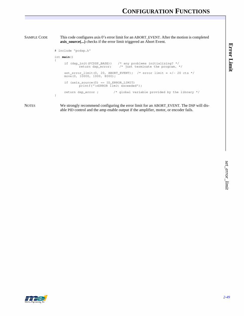
CONFIGURATION FUNCTIONS
2-49
Error L
imit
set_error_limit
SAMPLE CODE This code configures axis 0’s error limit for an ABORT_EVENT. After the motion is completed axis_source(...) checks if the error limit triggered an Abort Event.
# include "pcdsp.h"
int main(){
if (dsp_init(PCDSP_BASE)) /* any problems initializing? */return dsp_error; /* just terminate the program. */
set_error_limit(0, 20, ABORT_EVENT); /* error limit = +/- 20 cts */move(0, 10000, 1000, 8000);
if (axis_source(0) == ID_ERROR_LIMIT)printf("\nERROR limit exceeded");
return dsp_error ; /* global variable provided by the library */}
NOTES We strongly recommend configuring the error limit for an ABORT_EVENT. The DSP will dis-able PID control and the amp enable output if the amplifier, motor, or encoder fails.
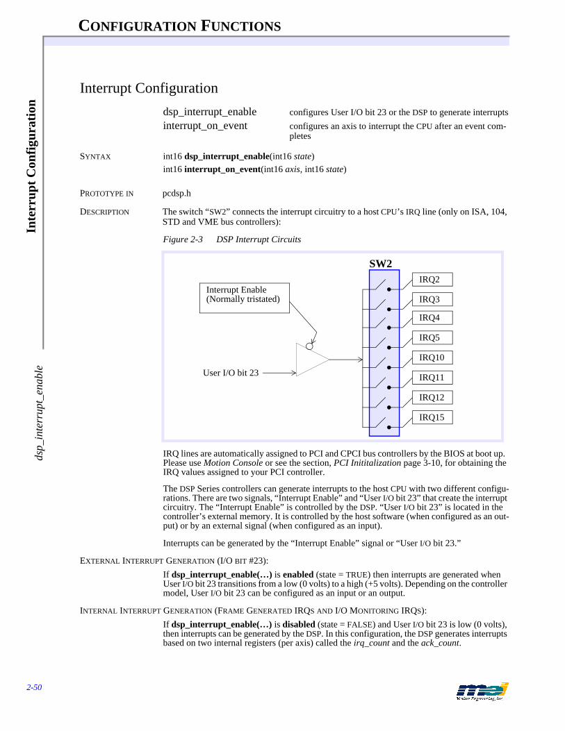
CONFIGURATION FUNCTIONS
2-50
Inte
rrup
t Con
figu
rati
onds
p_in
terr
upt_
enab
le
Interrupt Configuration
dsp_interrupt_enable configures User I/O bit 23 or the DSP to generate interruptsinterrupt_on_event configures an axis to interrupt the CPU after an event com-
pletes
SYNTAX int16 dsp_interrupt_enable(int16 state)int16 interrupt_on_event(int16 axis, int16 state)
PROTOTYPE IN pcdsp.h
DESCRIPTION The switch “SW2” connects the interrupt circuitry to a host CPU’s IRQ line (only on ISA, 104, STD and VME bus controllers):
Figure 2-3 DSP Interrupt Circuits
IRQ lines are automatically assigned to PCI and CPCI bus controllers by the BIOS at boot up. Please use Motion Console or see the section, PCI Inititalization page 3-10, for obtaining the IRQ values assigned to your PCI controller.
The DSP Series controllers can generate interrupts to the host CPU with two different configu-rations. There are two signals, “Interrupt Enable” and “User I/O bit 23” that create the interrupt circuitry. The “Interrupt Enable” is controlled by the DSP. “User I/O bit 23” is located in the controller’s external memory. It is controlled by the host software (when configured as an out-put) or by an external signal (when configured as an input).
Interrupts can be generated by the “Interrupt Enable” signal or “User I/O bit 23.”
EXTERNAL INTERRUPT GENERATION (I/O BIT #23): If dsp_interrupt_enable(…) is enabled (state = TRUE) then interrupts are generated when User I/O bit 23 transitions from a low (0 volts) to a high (+5 volts). Depending on the controller model, User I/O bit 23 can be configured as an input or an output.
INTERNAL INTERRUPT GENERATION (FRAME GENERATED IRQS AND I/O MONITORING IRQS):If dsp_interrupt_enable(…) is disabled (state = FALSE) and User I/O bit 23 is low (0 volts), then interrupts can be generated by the DSP. In this configuration, the DSP generates interrupts based on two internal registers (per axis) called the irq_count and the ack_count.
SW2
Interrupt Enable(Normally tristated)
IRQ2
IRQ3
IRQ4
IRQ5
IRQ10
IRQ11
IRQ12
IRQ15
User I/O bit 23
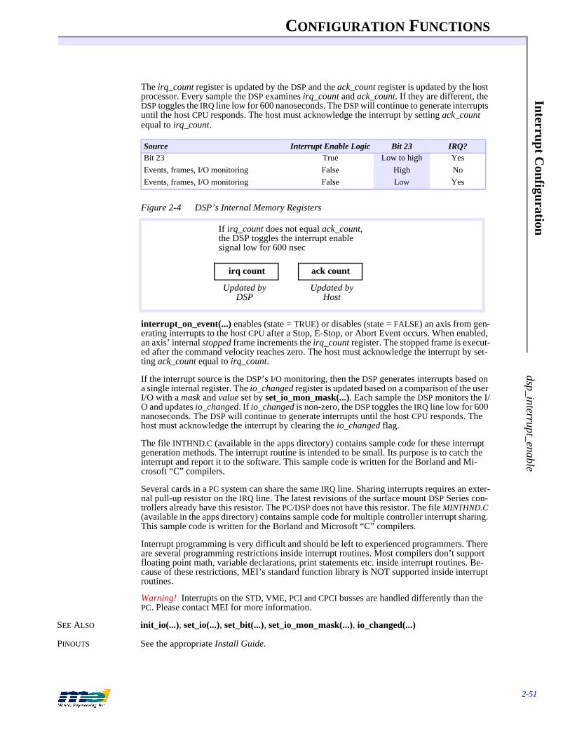
CONFIGURATION FUNCTIONS
2-51
Interrupt Configuration
dsp_interrupt_enable
The irq_count register is updated by the DSP and the ack_count register is updated by the host processor. Every sample the DSP examines irq_count and ack_count. If they are different, the DSP toggles the IRQ line low for 600 nanoseconds. The DSP will continue to generate interrupts until the host CPU responds. The host must acknowledge the interrupt by setting ack_count equal to irq_count.
Figure 2-4 DSP’s Internal Memory Registers
interrupt_on_event(...) enables (state = TRUE) or disables (state = FALSE) an axis from gen-erating interrupts to the host CPU after a Stop, E-Stop, or Abort Event occurs. When enabled, an axis’ internal stopped frame increments the irq_count register. The stopped frame is execut-ed after the command velocity reaches zero. The host must acknowledge the interrupt by set-ting ack_count equal to irq_count.
If the interrupt source is the DSP’s I/O monitoring, then the DSP generates interrupts based on a single internal register. The io_changed register is updated based on a comparison of the user I/O with a mask and value set by set_io_mon_mask(...). Each sample the DSP monitors the I/O and updates io_changed. If io_changed is non-zero, the DSP toggles the IRQ line low for 600 nanoseconds. The DSP will continue to generate interrupts until the host CPU responds. The host must acknowledge the interrupt by clearing the io_changed flag.
The file INTHND.C (available in the apps directory) contains sample code for these interrupt generation methods. The interrupt routine is intended to be small. Its purpose is to catch the interrupt and report it to the software. This sample code is written for the Borland and Mi-crosoft “C” compilers.
Several cards in a PC system can share the same IRQ line. Sharing interrupts requires an exter-nal pull-up resistor on the IRQ line. The latest revisions of the surface mount DSP Series con-trollers already have this resistor. The PC/DSP does not have this resistor. The file MINTHND.C (available in the apps directory) contains sample code for multiple controller interrupt sharing. This sample code is written for the Borland and Microsoft “C” compilers.
Interrupt programming is very difficult and should be left to experienced programmers. There are several programming restrictions inside interrupt routines. Most compilers don’t support floating point math, variable declarations, print statements etc. inside interrupt routines. Be-cause of these restrictions, MEI’s standard function library is NOT supported inside interrupt routines.
Warning! Interrupts on the STD, VME, PCI and CPCI busses are handled differently than the PC. Please contact MEI for more information.
SEE ALSO init_io(...), set_io(...), set_bit(...), set_io_mon_mask(...), io_changed(...)
PINOUTS See the appropriate Install Guide.
Source Interrupt Enable Logic Bit 23 IRQ?Bit 23 True Low to high YesEvents, frames, I/O monitoring False High NoEvents, frames, I/O monitoring False Low Yes
Updated by DSP
irq count ack count
If irq_count does not equal ack_count, the DSP toggles the interrupt enable signal low for 600 nsec
Updated by Host

CONFIGURATION FUNCTIONS
2-52
Inte
rrup
t Con
figu
rati
onds
p_in
terr
upt_
enab
le
RETURN VALUES
NOTES Don't forget to set the IRQ jumper or switch on the controller.
Returnsdsp_interrupt_enable(...)interrupt_on_event(...)
Error return codes (see Error Handling on page 3-13)

CONFIGURATION FUNCTIONS
2-53
SER
CO
S Initialization serc_reset
SERCOS Initialization
serc_reset resets the controller and initializes SERCOS communicationget_sercos_phase reads the SERCOS ring initialization phase
SYNTAX int16 serc_reset(int16 baud, int16 ndrives, DRIVE_INFO * dinfo)int16 get_sercos_phase(int16 * phase)
PROTOTYPE IN sercos.h, sercrset.h
DESCRIPTION serc_reset(...) is required to initialize a SERCOS ring. Be sure to initialize the controller first with do_dsp(...) or dsp_init(...). Then, a call to serc_reset(...) will reset the controller and ini-tialize the SERCOS ring in the following phases:
baud specifies the ring communication rate in bits per second. baud can be specified with one of the following #defines:
ndrives specifies the number of SERCOS nodes to be initialized. The valid range for ndrives is between 1 and 8. Nodes can be any SERCOS compatible slave device. These include servo drives, digital I/O modules, A/D modules, D/A modules, position feedback modules, etc.
* dinfo is a pointer to an array of DRIVE_INFO structures. The configuration for each SERCOS node is specified by a DRIVE_INFO structure:
typedef struct {int16 drive_axis; /* controller’s axis number */unsigned16 drive_addr; /* node address */unsigned16 drive_mode; /* operational mode */unsigned16 drive_mfg; /* node manufacturer */} DRIVE_INFO;
typedef DRIVE_INFO *DriveInfo;
drive_axis is the controller’s axis number assigned to a SERCOS node. The valid range for drive_axis is between 0 and 7.
drive_addr is the SERCOS node’s address. Each SERCOS node must have its own unique ad-dress. The valid range for drive_addr is between 1 and 254 (drive_addr = 0 is reserved for broadcast messages).
Table 2-35 SERCOS Phases
Phase Description
0 Start synchronized real-time communication1 Find the drives and I/O modules2 Configure the communication data structure3 Start communication, verify proper operation4 Operational mode
Table 2-36 Baud Rates
#define Value Explanation
BIT_RATE2 2 2 Mbits/secBIT_RATE4 4 4 Mbits/sec
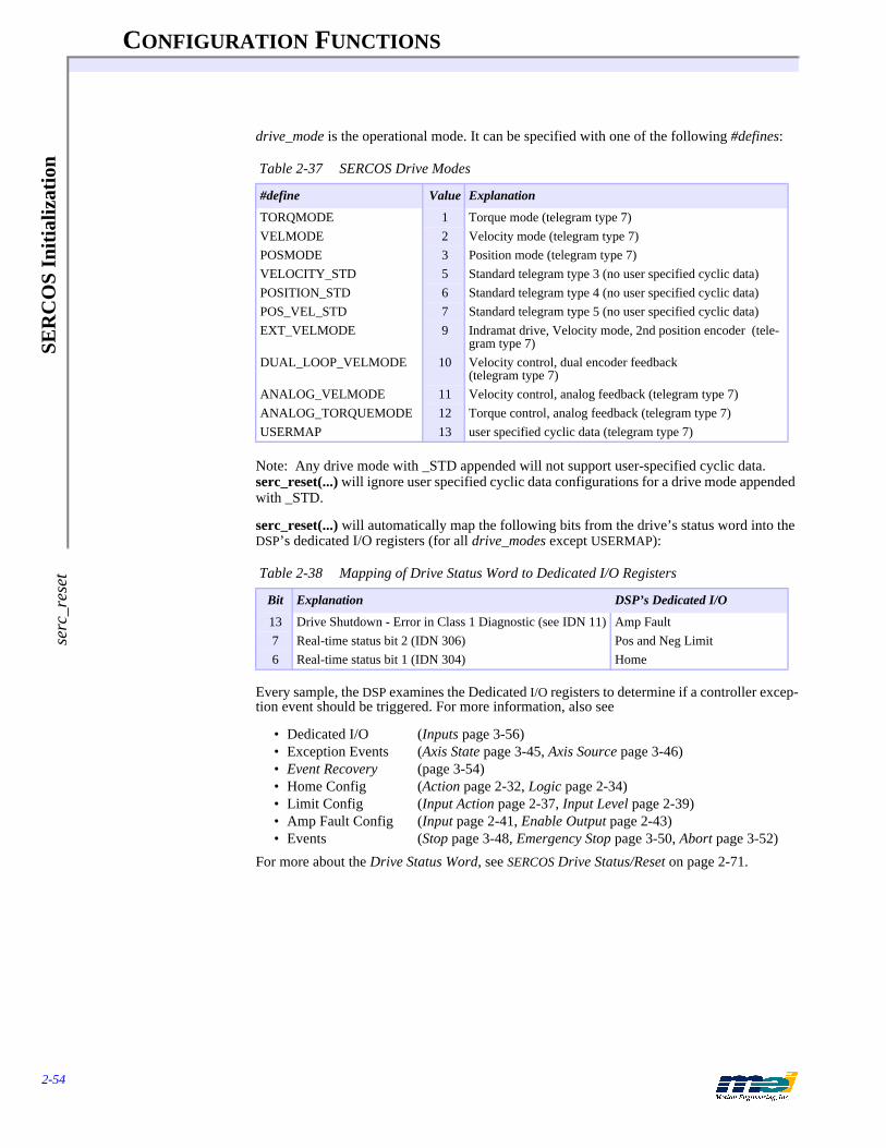
CONFIGURATION FUNCTIONS
2-54
SER
CO
S In
itia
lizat
ion
serc
_res
et
drive_mode is the operational mode. It can be specified with one of the following #defines:
Note: Any drive mode with _STD appended will not support user-specified cyclic data. serc_reset(...) will ignore user specified cyclic data configurations for a drive mode appended with _STD.
serc_reset(...) will automatically map the following bits from the drive’s status word into the DSP’s dedicated I/O registers (for all drive_modes except USERMAP):
Every sample, the DSP examines the Dedicated I/O registers to determine if a controller excep-tion event should be triggered. For more information, also see
• Dedicated I/O (Inputs page 3-56)• Exception Events (Axis State page 3-45, Axis Source page 3-46)• Event Recovery (page 3-54)• Home Config (Action page 2-32, Logic page 2-34)• Limit Config (Input Action page 2-37, Input Level page 2-39) • Amp Fault Config (Input page 2-41, Enable Output page 2-43)• Events (Stop page 3-48, Emergency Stop page 3-50, Abort page 3-52)
For more about the Drive Status Word, see SERCOS Drive Status/Reset on page 2-71.
Table 2-37 SERCOS Drive Modes
#define Value Explanation
TORQMODE 1 Torque mode (telegram type 7)VELMODE 2 Velocity mode (telegram type 7)POSMODE 3 Position mode (telegram type 7)VELOCITY_STD 5 Standard telegram type 3 (no user specified cyclic data)POSITION_STD 6 Standard telegram type 4 (no user specified cyclic data)POS_VEL_STD 7 Standard telegram type 5 (no user specified cyclic data)EXT_VELMODE 9 Indramat drive, Velocity mode, 2nd position encoder (tele-
gram type 7)DUAL_LOOP_VELMODE 10 Velocity control, dual encoder feedback
(telegram type 7)ANALOG_VELMODE 11 Velocity control, analog feedback (telegram type 7)ANALOG_TORQUEMODE 12 Torque control, analog feedback (telegram type 7)USERMAP 13 user specified cyclic data (telegram type 7)
Table 2-38 Mapping of Drive Status Word to Dedicated I/O Registers
Bit Explanation DSP’s Dedicated I/O
13 Drive Shutdown - Error in Class 1 Diagnostic (see IDN 11) Amp Fault7 Real-time status bit 2 (IDN 306) Pos and Neg Limit6 Real-time status bit 1 (IDN 304) Home

CONFIGURATION FUNCTIONS
2-55
SER
CO
S Initialization serc_reset
drive_mfg is the SERCOS node manufacturer. It can be specified with one of the following #de-fines:
If a #define does not match a particular SERCOS node’s manufacturer, then use OTHER. Also, please contact Motion Engineering with any information concerning SERCOS node manufac-turers not specified with a #define.
Use get_sercos_phase(...) to read the SERCOS ring’s current initialization phase.
SEE ALSO dsp_init(...), do_dsp(...), configure_phase2_idns(...), configure_phase3_idns(...), configure_mdt_data(...), configure_at_data(...), enable_amplifier(...), disable_amplifier(...), get_drive_status(...)
RETURN VALUES
SAMPLE CODE This code initializes SERCOS communication with an Indramat servo drive:
#include “pcdsp.h”#include “sercos.h”#include “sercrset.h”
#define NODES 1 /* Number of nodes on SERCOS ring */#define AXIS 0#define NODE_ADDR 1
DRIVE_INFO drive_info[NODES] = {/* {Axis, Drive address, Operation mode, Manufacturer} */
{AXIS, NODE_ADDR, POSMODE, INDRAMAT}};
int main(void){
if (dsp_init(PCDSP_BASE)) /* any problems initializing? */return dsp_error;
if (serc_reset(BIT_RATE2, NODES, drive_info))return dsp_error;
enable_amplifier(AXIS); /* enable servo drive */
return dsp_error;}
NOTES The SINITxx.C sample programs demonstrate SERCOS communication initialization for several different drives, I/O modules, and configurations.
Table 2-39 SERCOS Manufacturer defines
#define Value Manufacturer
LUTZE 0 LutzePACSCI 1 Pacific ScientificMODICON 2 AEG/ModiconINDRAMAT 3 IndramatKOLLMORGEN 4 KollmorgenMEI 5 Motion Engineering, Inc.SANYO_DENKI 6 Sanyo DenkiOTHER 32 Not manufacturer-specific
Returnsserc_reset(...)get_sercos_phase(...)
Error return codes (see Error Handling on page 3-13)

CONFIGURATION FUNCTIONS
2-56
SER
CO
S P
hase
2 &
3 I
DN
s C
onfi
gura
tion
conf
igur
e_ph
ase2
_idn
s
SERCOS Phase 2 & 3 IDNs Configuration
configure_phase2_idns specifies IDNs to be set during Phase 2 initializationconfigure_phase3_idns specifies IDNs to be set during Phase 3 initialization
SYNTAX int16 configure_phase2_idns(unsigned16 nidns, DRIVE_IDNS * didns)int16 configure_phase3_idns(unsigned16 nidns, DRIVE_IDNS * didns)
PROTOTYPE IN sercos.h, sercrset.h
DESCRIPTION Several IDNs can only be accessed during the SERCOS ring initialization Phases 2 and 3. Typ-ically, these IDNs contain operational data that is used during Phase 4 (normal operation).configure_phase2_idns(...) specifies the IDNs to be set by serc_reset(…) during SERCOS ring initialization Phase 2.
configure_phase3_idns(...) specifies the IDNs that will be set by serc_reset(…) during SER-COS ring initialization Phase 3.
Be sure to always invoke configure_phase2_idns(…) and/or configure_phase3_idns(…) be-fore serc_reset(…).
nidns specifies the number of IDNs to be set.
* didns is a pointer to an array of DRIVE_IDNS structures. The configuration for each IDN is specified by a DRIVE_IDNS structure:
typedef struct {unsigned16 idn;long value;unsigned16 drive_addr;} DRIVE_IDNS;
typedef DRIVE_IDNS *DriveIdns;
idn is the Identification Number (IDN). The valid range for idn is between 1 and 65535. idn’s 1 to 32767 are defined in the SERCOS specification. IDNs 32768 to 65535 are defined by the node (drive) manufacturer. For more information, please consult the node (drive) manufactur-er’s documentation.
value is the 32 bit operating data for the specified idn.
drive_addr is the SERCOS node’s address. Each SERCOS node must have it’s own unique ad-dress. The valid range for drive_addr is between 1 and 254 (drive_addr = 0 is reserved for broadcast messages).
SEE ALSO serc_reset(…)
RETURN VALUES
Returnsconfigure_phase2_idns(...)configure_phase3_idns(...)
Error return codes (see Error Handling on page 3-13)
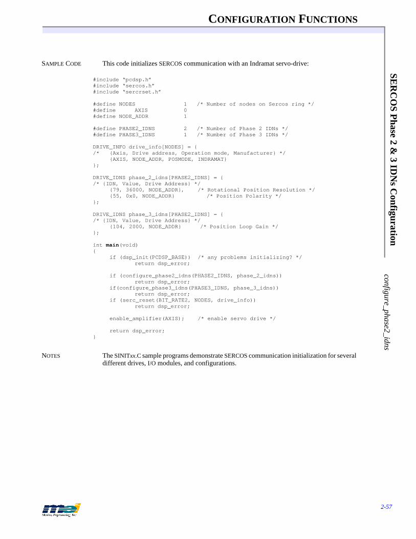
CONFIGURATION FUNCTIONS
2-57
SER
CO
S Phase 2 &
3 IDN
s Configuration
configure_phase2_idns
SAMPLE CODE This code initializes SERCOS communication with an Indramat servo-drive:
#include “pcdsp.h”#include “sercos.h”#include “sercrset.h”
#define NODES 1 /* Number of nodes on Sercos ring */#define AXIS 0#define NODE_ADDR 1
#define PHASE2_IDNS 2 /* Number of Phase 2 IDNs */#define PHASE3_IDNS 1 /* Number of Phase 3 IDNs */
DRIVE_INFO drive_info[NODES] = {/* {Axis, Drive address, Operation mode, Manufacturer} */
{AXIS, NODE_ADDR, POSMODE, INDRAMAT}};
DRIVE_IDNS phase_2_idns[PHASE2_IDNS] = {/* {IDN, Value, Drive Address} */
{79, 36000, NODE_ADDR}, /* Rotational Position Resolution */{55, 0x0, NODE_ADDR} /* Position Polarity */
};
DRIVE_IDNS phase_3_idns[PHASE2_IDNS] = {/* {IDN, Value, Drive Address} */
{104, 2000, NODE_ADDR} /* Position Loop Gain */};
int main(void){
if (dsp_init(PCDSP_BASE)) /* any problems initializing? */return dsp_error;
if (configure_phase2_idns(PHASE2_IDNS, phase_2_idns))return dsp_error;
if(configure_phase3_idns(PHASE3_IDNS, phase_3_idns))return dsp_error;
if (serc_reset(BIT_RATE2, NODES, drive_info))return dsp_error;
enable_amplifier(AXIS); /* enable servo drive */
return dsp_error;}
NOTES The SINITxx.C sample programs demonstrate SERCOS communication initialization for several different drives, I/O modules, and configurations.
CONFIGURATION FUNCTIONS
2-58
SER
CO
S C
yclic
Dat
a C
onfi
gura
tion
conf
igur
e_at
_dat
a
SERCOS Cyclic Data Configuration
configure_at_data specifies IDNs to be placed in the Amplifier Telegram.configure_mdt_data specifies IDNs to be placed in the Master Data Telegram.
SYNTAX int16 configure_at_data(unsigned16 natdata, CYCLIC_DATA * at_data)int16 configure_mdt_data(unsigned16 nmdtdata, CYCLIC_DATA * mdt_data)
PROTOTYPE IN sercrset.h
DESCRIPTION Some IDNs can be accessed through cyclic data. Every SERCOS loop update, the cyclic data is updated by the master controller and the nodes. The cyclic data contains the Amplifier Tele-gram(s) (one per SERCOS node) and the Master Data Telegram (sent by the controller).configure_at_data(…) specifies the IDNs to be placed in the cyclic data by serc_reset(…) during SERCOS ring initialization.
configure_mdt_data(...) specifies the IDNs to be placed in the cyclic data by serc_reset(…) during SERCOS ring initialization.
Be sure to always invoke configure_at_data(…) and/or configure_mdt_data(…) before serc_reset(…).
natdata specifies the number of IDNs to be placed in the Amplifier Telegram. nmdtdata spec-ifies the number of IDNs to be placed in the Master Data Telegram. The valid range for natdata and nmdtdata is between 1 and 30. A maximum of 30 words (16 bits) can be placed in an axis’ AT or MDT.
* at_data and * mdt_data are pointers to arrays of CYCLIC_DATA structures. The user speci-fied cyclic data is defined by a CYCLIC_DATA structure:
typedef struct {unsigned16 idn;unsigned16 drive_addr;} CYCLIC_DATA;typedef CYCLIC_DATA * CyclicData;
The specific IDNs that can be placed into the AT or MDT is defined by the SERCOS node man-ufacturer. The list of configurable data for the AT can be found in IDN 187. The list of config-urable data for the MDT can be found in IDN 188.
After the ring has been successfully initialized with serc_reset(…), the AT and MDT cyclic data can be accessed with read_cyclic_at_data(…), read_cyclic_mdt_data(…), and write_cyclic_mdt_data(…).
SEE ALSO serc_reset(…), read_cyclic_at_data(…), read_cyclic_mdt_data(…), write_cyclic_mdt_data(…)
RETURN VALUES
Returnsconfigure_at_data(...)configure_mdt_data(...)
Error return codes (see Error Handling on page 3-13)

CONFIGURATION FUNCTIONS
2-59
SER
CO
S Cyclic D
ata Configuration
configure_at_data
SAMPLE CODE This code initializes SERCOS communication with an Indramat servo-drive:
#include “pcdsp.h”#include “sercos.h”#include “sercrset.h”
#define NODES 1 /* Number of nodes on SERCOS ring */#define AXIS 0#define NODE_ADDR 1
#define AT_IDNS 1 /* Number of IDNS for the AT */#define MDT_IDNS 1 /* Number of IDNS for the MDT */
DRIVE_INFO drive_info[NODES] = {/* {Axis, Drive address, Operation mode, Manufacturer} */
{AXIS, NODE_ADDR, POSMODE, INDRAMAT}};
CYCLIC_DATA at_idns[AT_IDNS] = {/* {IDN, Drive Address} */
{130, NODE_ADDR} /* Probe 1, Positive Edge Position Value */};
CYCLIC_DATA mdt_idns[MDT_IDNS] = {/* {IDN, Drive Address} */
{91, NODE_ADDR} /* Bipolar Velocity Limit */};
int main(void){
if (dsp_init(PCDSP_BASE)); /* any problems initializing? */return dsp_error;
if (configure_at_data(AT_IDNS, at_idns))return dsp_error;
if (configure_mdt_data(MDT_IDNS, mdt_idns))return dsp_error;
if (serc_reset(BIT_RATE2, NODES, drive_info))return dsp_error;
enable_amplifier(AXIS); /* enable servo drive */
return dsp_error;}
NOTES The SINITxx.C sample programs demonstrate SERCOS communication initialization for several different drives, I/O modules, and configurations.
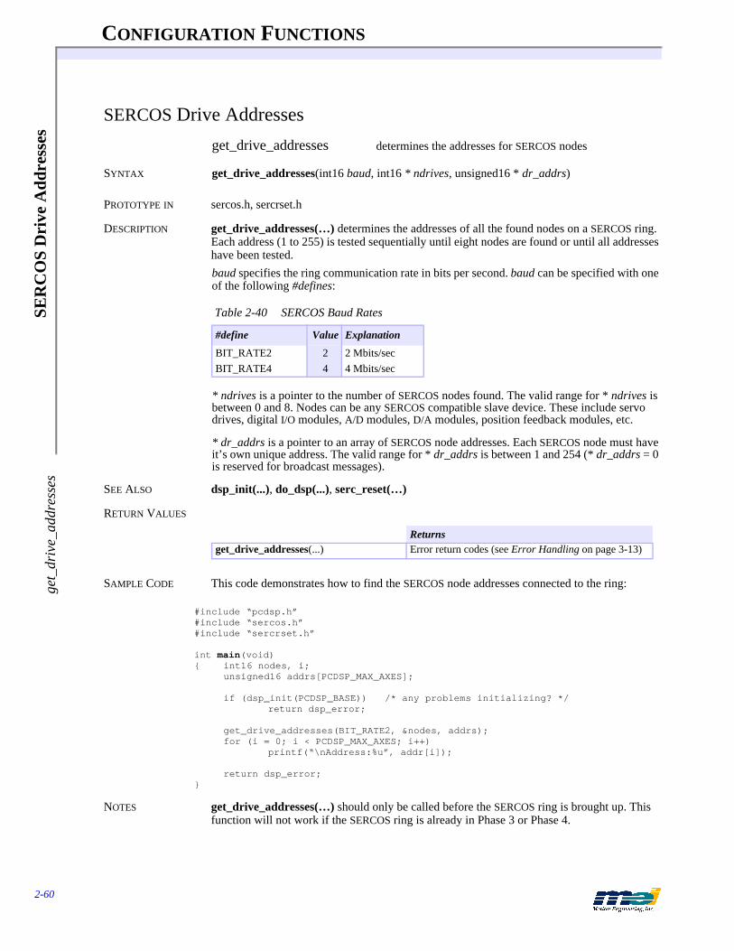
CONFIGURATION FUNCTIONS
2-60
SER
CO
S D
rive
Add
ress
esge
t_dr
ive_
addr
esse
s
SERCOS Drive Addresses
get_drive_addresses determines the addresses for SERCOS nodes
SYNTAX get_drive_addresses(int16 baud, int16 * ndrives, unsigned16 * dr_addrs)
PROTOTYPE IN sercos.h, sercrset.h
DESCRIPTION get_drive_addresses(…) determines the addresses of all the found nodes on a SERCOS ring. Each address (1 to 255) is tested sequentially until eight nodes are found or until all addresses have been tested.baud specifies the ring communication rate in bits per second. baud can be specified with one of the following #defines:
* ndrives is a pointer to the number of SERCOS nodes found. The valid range for * ndrives is between 0 and 8. Nodes can be any SERCOS compatible slave device. These include servo drives, digital I/O modules, A/D modules, D/A modules, position feedback modules, etc.
* dr_addrs is a pointer to an array of SERCOS node addresses. Each SERCOS node must have it’s own unique address. The valid range for * dr_addrs is between 1 and 254 (* dr_addrs = 0 is reserved for broadcast messages).
SEE ALSO dsp_init(...), do_dsp(...), serc_reset(…)
RETURN VALUES
SAMPLE CODE This code demonstrates how to find the SERCOS node addresses connected to the ring:
#include “pcdsp.h”#include “sercos.h”#include “sercrset.h”
int main(void){ int16 nodes, i;
unsigned16 addrs[PCDSP_MAX_AXES];
if (dsp_init(PCDSP_BASE)) /* any problems initializing? */return dsp_error;
get_drive_addresses(BIT_RATE2, &nodes, addrs);for (i = 0; i < PCDSP_MAX_AXES; i++)
printf(“\nAddress:%u”, addr[i]);
return dsp_error;}
NOTES get_drive_addresses(…) should only be called before the SERCOS ring is brought up. This function will not work if the SERCOS ring is already in Phase 3 or Phase 4.
Table 2-40 SERCOS Baud Rates
#define Value Explanation
BIT_RATE2 2 2 Mbits/secBIT_RATE4 4 4 Mbits/sec
Returnsget_drive_addresses(...) Error return codes (see Error Handling on page 3-13)

CONFIGURATION FUNCTIONS
2-61
SER
CO
S Change O
peration Mode
change_operation_mode
SERCOS Change Operation Mode
change_operation_mode switches the operation mode for a SERCOS drive
SYNTAX int16 change_operation_mode(int16 axis, unsigned16 mode)
PROTOTYPE IN sercos.h
DESCRIPTION During serc_reset(…) the primary and optional secondary operation mode(s) for a SERCOS drive can be configured. The operation mode defines the control loops for the controller and drive. SERCOS supports Torque, Velocity and Position digital control loops between the con-troller and the drive.change_operation_mode(...) switches the SERCOS drive operational mode between the pri-mary and secondary modes. Switching operation modes can be performed without disabling the drive or re-initializing the SERCOS ring. The primary and secondary operation modes are defined by IDNs 32, 33, 34, and 35. The following operation modes are available:
The range for mode is between 0 and 3. Please consult the drive manufacturer’s documentation for more information concerning operation modes and operation mode switching.
SEE ALSO configure_phase2_idns(...), serc_reset(…), set_idn(…), get_idn(…)
RETURN VALUES
Table 2-41 SERCOS Operating Modes
Mode Explanation
0 Primary operation mode (defined by IDN 32)1 Secondary operation mode 1 (defined by IDN 33)2 Secondary operation mode 2 (defined by IDN 34)3 Secondary operation mode 3 (defined by IDN 35)
Returnschange_operation_mode(...) Error return codes (see Error Handling on page 3-13)
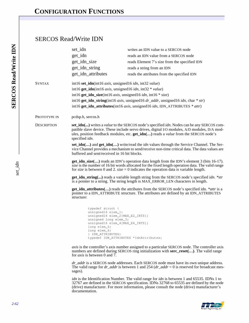
CONFIGURATION FUNCTIONS
2-62
SER
CO
S R
ead/
Wri
te I
DN
set_
idn
SERCOS Read/Write IDN
set_idn writes an IDN value to a SERCOS nodeget_idn reads an IDN value from a SERCOS nodeget_idn_size reads Element 7’s size from the specified IDN
get_idn_string reads a string from an IDN
get_idn_attributes reads the attributes from the specified IDN
SYNTAX int16 set_idn(int16 axis, unsigned16 idn, int32 value)int16 get_idn(int16 axis, unsigned16 idn, int32 * value)int16 get_idn_size(int16 axis, unsigned16 idn, int16 * size)int16 get_idn_string(int16 axis, unsigned16 dr_addr, unsigned16 idn, char * str)int16 get_idn_attributes(int16 axis, unsigned16 idn, IDN_ATTRIBUTES * attr)
PROTOTYPE IN pcdsp.h, sercos.h
DESCRIPTION set_idn(...) writes a value to the SERCOS node’s specified idn. Nodes can be any SERCOS com-patible slave device. These include servo drives, digital I/O modules, A/D modules, D/A mod-ules, position feedback modules, etc. get_idn(…) reads a value from the SERCOS node’s specified idn.set_idn(…) and get_idn(…) write/read the idn values through the Service Channel. The Ser-vice Channel provides a mechanism to send/receive non-time critical data. The data values are buffered and sent/received in 16 bit blocks.
get_idn_size(…) reads an IDN’s operation data length from the IDN’s element 3 (bits 16-17). size is the number of 16 bit words allocated for the fixed length operation data. The valid range for size is between 0 and 2. size = 0 indicates the operation data is variable length.
get_idn_string(...) reads a variable length string from the SERCOS node’s specified idn. *str is a pointer to a string. The string length is MAX_ERROR_LEN characters in length.
get_idn_attributes(…) reads the attributes from the SERCOS node’s specified idn. *attr is a pointer to a IDN_ATTRIBUTE structure. The attributes are defined by an IDN_ATTRIBUTES structure:
typedef struct {unsigned16 elem_1;unsigned16 elem_2[MAX_E2_INTS];unsigned long elem_3;unsigned16 elem_4[MAX_E4_INTS];long elem_5;long elem_6;} IDN_ATTRIBUTES;typedef IDN_ATTRIBUTES *IdnAttributes;
axis is the controller’s axis number assigned to a particular SERCOS node. The controller axis numbers are defined during SERCOS ring initialization with serc_reset(…). The valid range for axis is between 0 and 7.
dr_addr is a SERCOS node addresses. Each SERCOS node must have its own unique address. The valid range for dr_addr is between 1 and 254 (dr_addr = 0 is reserved for broadcast mes-sages).
idn is the Identification Number. The valid range for idn is between 1 and 65535. IDNs 1 to 32767 are defined in the SERCOS specification. IDNs 32768 to 65535 are defined by the node (drive) manufacturer. For more information, please consult the node (drive) manufacturer’s documentation.

CONFIGURATION FUNCTIONS
2-63
SER
CO
S Read/W
rite IDN
set_idn
value is the 32 bit operating data for the specified idn. IDNs support either 32 bit or 16 bit data values. set_idn(…) and get_idn(…) automatically mask the upper bits for 16 bit data value siz-es.
SEE ALSO configure_phase2_idns(...), configure_phase3_idns(…), serc_reset(…)
RETURN VALUES
SAMPLE CODE This code demonstrates how to read an IDN value. Be sure to always initialize SERCOS com-munication with serc_reset(…) before reading/writing IDNs:
#include “pcdsp.h”#include “sercos.h”
#define AXIS 0#define ADDR 1 /* Node Address */#define IDN 30 /* Manufacturer Version */
int main(void){ int16 size;
int32 value;char string[MAX_ERROR_LEN];
if (dsp_init(PCDSP_BASE)) /* any problems initializing? */return dsp_error;
get_idn_size(AXIS, IDN, &size);
if (size){ get_idn(AXIS, IDN, &value);
printf("\nData length(words) is: %d\n", size);printf("\nValue: %ld", value);
}else{ get_idn_string(AXIS, 1, IDN, string);
printf("\nData length is variable\n");printf("\n%s", string);
}
return dsp_error;}
Returnsset_idn(...)get_idn(...)get_idn_size(...)get_idn_string(...)get_idn_attributes(...)
Error return codes (see Error Handling on page 3-13)

CONFIGURATION FUNCTIONS
2-64
SER
CO
S R
ead/
Wri
te M
ulti
ple
IDN
sse
t_id
ns
SERCOS Read/Write Multiple IDNs
set_idns writes an array of IDN values to a SERCOS nodeget_idns reads an array of IDN values from a SERCOS node
SYNTAX int16 set_idns(int16 axis, unsigned16 dr_addr, unsigned16 idns, IDNS * idns)int16 get_idns(int16 axis, unsigned16 dr_addr, unsigned16 firstidn, unsigned16 idns, IDNS * idns)
PROTOTYPE IN sercos.h
DESCRIPTION set_idns(...) writes an array of sequential IDN values to a SERCOS node. get_idns(…) reads an array of sequential IDN values from a SERCOS node. Nodes can be any SERCOS compatible slave device. These include servo drives, digital I/O modules, A/D mod-ules, D/A modules, position feedback modules, etc.
axis is the controller’s axis number assigned to a particular SERCOS node. The controller axis numbers are defined during SERCOS ring initialization with serc_reset(…). The valid range for axis is between 0 and 7.
dr_addr is a SERCOS node addresses. Each SERCOS node must have it’s own unique address. The valid range for dr_addr is between 1 and 254 (dr_addr = 0 is reserved for broadcast mes-sages).
If the SERCOS communication ring is in phase 3 or 4, then the node is specified by axis. If the ring is in phase 1 or 2, then the drive is specified by dr_addr.
*idns is a pointer to an array of IDNS structures:
typedef struct {unsigned16 idn;long value;int16 error; /* error code from set/get_idn(...) */} IDNS;typedef IDNS *Idns;
idn is the Identification Number. The valid range for idn is between 1 and 65535. IDNs 1 to 32767 are defined in the SERCOS specification. IDNs 32768 to 65535 are defined by the node (drive) manufacturer. For more information, please consult the node (drive) manufacturer’s documentation.
value is the 32 bit operating data for the specified idn. IDNs support either 32 bit or 16 bit data values. set_idns(…) and get_idns(…) automatically mask the upper bits for 16 bit data value sizes.
error is the error code returned by the internal call to set/get_idn(…). set_idns(…) will not write values to IDNs that have a non-zero number in the error field. Any failure to read/write an IDN value will be stored in error.
Generally, do not write to IDNs 1 through 30 with set_idns(…). IDNs 1 through 30 contain SERCOS ring operation data and are initialized during serc_reset(…).
set_idns(…) and get_idns(…) write/read the idn values through the Service Channel. The Ser-vice Channel provides a mechanism to send/receive non-time critical data. The data values are buffered and sent/received in 16 bit blocks.
SEE ALSO serc_reset(…), set_idn(…), get_idn(…)

CONFIGURATION FUNCTIONS
2-65
SER
CO
S Read/W
rite Multiple ID
Ns
set_idns
RETURN VALUES
SAMPLE CODE This code demonstrates how to read an array of IDN values. Be sure to always initialize SER-COS communication with serc_reset(…) before reading/writing IDNs:
#include “pcdsp.h”#include “sercos.h”
#define AXIS 0#define ADDR 1 /* Node Address */#define FIRST_IDN 30
#define TOTAL 400 /* Number of IDNs */IDNS buffer[TOTAL];
int main(void){ int16 i;
if (dsp_init(PCDSP_BASE)) /* any problems initializing? */return dsp_error;
get_idns(AXIS, ADDR, FIRST_IDN, TOTAL, buffer);for(i = 0; i < TOTAL; i++)
if (!buffer[i].error)printf("S-0-%4d:\t%ld\n", buffer[i].idn, buffer[i].value);
get_idns(axis, srcaddr, 0x8000, 100, buffer);for(i = 0; i < 100; i++)
if (!buffer[i].error)printf("P-0-%4d:\t%ld\n", (buffer[i].idn - 0x8000),
buffer[i].value);
return dsp_error;}
Returnsset_idns(...)get_idns(...)
Error return codes (see Error Handling on page 3-13)

CONFIGURATION FUNCTIONS
2-66
SER
CO
S P
roce
dure
sst
art_
exec
_pro
cedu
re
SERCOS Procedures
start_exec_procedure starts a SERCOS drive procedurecancel_exec_procedure cancels a SERCOS drive procedureexec_procedure_done determines a SERCOS drive procedure’s completion
SYNTAX int16 start_exec_procedure(int16 axis, unsigned16 procedure)int16 cancel_exec_procedure(int16 axis, unsigned16 procedure)int16 exec_procedure_done(int16 axis, unsigned16 procedure, int16 * done)
PROTOTYPE IN sercos.h
DESCRIPTION Procedures are internal processes that occur in a SERCOS drive or I/O module. The drive pro-cedures execute independently of the controller. Typically, drive procedures are lengthy and complex processes.start_exec_procedure(...) initiates a drive procedure assigned to the specified controller axis. cancel_exec_procedure(...) cancels a drive procedure assigned to the specified controller axis. exec_procedure_done(...) determines if a drive procedure assigned to the specified controller axis has completed.
axis is the controller’s axis number assigned to a particular SERCOS node. The controller axis numbers are defined during SERCOS ring initialization with serc_reset(…). The valid range for axis is between 0 and 7.
procedure is defined by an Identification Number (IDN). The valid range for procedure is be-tween 1 and 65535. IDNs 1 to 32767 are defined in the SERCOS specification. IDNs 32768 to 65535 are defined by the node (drive) manufacturer. For more information, please consult the node (drive) manufacturer’s documentation.
Procedures and IDNs share the same data block structure. The data block’s attribute element 3 defines if the IDN should be handled as a Procedure.
The start or end of a procedure is handled through the Service Channel (non-cyclic data block). After the drive or I/O module receives a procedure command, it responds with a procedure command acknowledgment and turns on the “busy” bit in its drive status word. After the Pro-cedure completes, the drive or I/O module will clear the “busy” bit.
Generally, the time required to complete a drive procedure is unknown. Some procedures are completed by the drive. Other procedures must be completed by the controller with cancel_exec_procedure(...). Please consult the SERCOS node manufacturer’s documentation for more detailed information.
SEE ALSO set_idn(…), get_idn(…), serc_reset(…), get_drive_status(...)
RETURN VALUES
Returnsstart_exec_procedure(...)cancel_exec_procedure(...)exec_procedure_done(...)
Error return codes (see Error Handling on page 3-13)
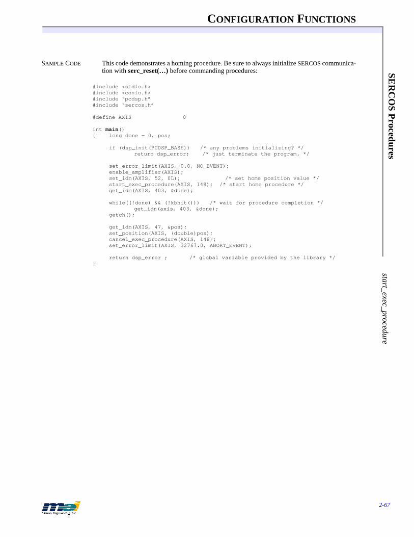
CONFIGURATION FUNCTIONS
2-67
SER
CO
S Procedures
start_exec_procedure
SAMPLE CODE This code demonstrates a homing procedure. Be sure to always initialize SERCOS communica-tion with serc_reset(…) before commanding procedures:
#include <stdio.h>#include <conio.h>#include “pcdsp.h”#include “sercos.h”
#define AXIS 0
int main(){ long done = 0, pos;
if (dsp_init(PCDSP_BASE)) /* any problems initializing? */return dsp_error; /* just terminate the program. */
set_error_limit(AXIS, 0.0, NO_EVENT);enable_amplifier(AXIS);set_idn(AXIS, 52, 0L); /* set home position value */start_exec_procedure(AXIS, 148); /* start home procedure */get_idn(AXIS, 403, &done);
while((!done) && (!kbhit())) /* wait for procedure completion */get_idn(axis, 403, &done);
getch();
get_idn(AXIS, 47, &pos);set_position(AXIS, (double)pos);cancel_exec_procedure(AXIS, 148);set_error_limit(AXIS, 32767.0, ABORT_EVENT);
return dsp_error ; /* global variable provided by the library */}
CONFIGURATION FUNCTIONS
2-68
SER
CO
S R
ead/
Wri
te C
yclic
Dat
are
ad_c
yclic
_at_
data
SERCOS Read/Write Cyclic Data
read_cyclic_at_data reads cyclic data from an Amplifier Telegramread_cyclic_mdt_data reads cyclic data from the Master Data Telegramwrite_cyclic_mdt_data writes cyclic data to the Master Data Telegram
SYNTAX int16 read_cyclic_at_data(int16 axis, unsigned16 offset)int16 read_cyclic_mdt_data(int16 axis, unsigned16 offset)int16 write_cyclic_mdt_data(int16 axis, unsigned16 offset, int16 data)
PROTOTYPE IN sercos.h
DESCRIPTION Some IDNs can be accessed through cyclic data Every SERCOS loop update, the cyclic data is updated by the master controller and the nodes. The cyclic data contains the Amplifier Tele-gram(s) (one per SERCOS node) and the Master Data Telegram (sent by the controller).read_cyclic_at_data(...) reads a 16-bit value from the Amplifier Telegram’s user-configured cyclic data.
read_cyclic_mdt_data(…) reads a 16-bit value from the Master Data Telegram’s user-config-ured cyclic data.
write_cyclic_mdt_data(...) writes a 16-bit value to the Master Data Telegram’s user-config-ured cyclic data.
axis is the controller’s axis number assigned to a particular SERCOS node. The controller axis numbers are defined during SERCOS ring initialization with serc_reset(…). The valid range for axis is between 0 and 7.
offset specifies the location in the AT or MDT to read/write the 16-bit data word. The data and offset configurations are based on the CYCLIC_DATA structures passed to configure_at_data(…) and configure_mdt_data(…).
SEE ALSO configure_at_data(…), configure_mdt_data(…), serc_reset(…)
RETURN VALUES
Returnsread_cyclic_at_data(...)read_cyclic_mdt_data(...)write_cyclic_mdt_data(...)
Error return codes (see Error Handling on page 3-13)
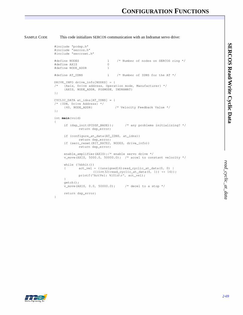
CONFIGURATION FUNCTIONS
2-69
SER
CO
S Read/W
rite Cyclic D
ata read_cyclic_at_data
SAMPLE CODE This code initializes SERCOS communication with an Indramat servo drive:
#include “pcdsp.h”#include “sercos.h”#include “sercrset.h”
#define NODES 1 /* Number of nodes on SERCOS ring */#define AXIS 0#define NODE_ADDR 1
#define AT_IDNS 1 /* Number of IDNS for the AT */
DRIVE_INFO drive_info[NODES] = {/* {Axis, Drive address, Operation mode, Manufacturer} */
{AXIS, NODE_ADDR, POSMODE, INDRAMAT}};
CYCLIC_DATA at_idns[AT_IDNS] = {/* {IDN, Drive Address} */
{40, NODE_ADDR} /* Velocity Feedback Value */};
int main(void){
if (dsp_init(PCDSP_BASE)); /* any problems initializing? */return dsp_error;
if (configure_at_data(AT_IDNS, at_idns))return dsp_error;
if (serc_reset(BIT_RATE2, NODES, drive_info))return dsp_error;
enable_amplifier(AXIS);/* enable servo drive */v_move(AXIS, 5000.0, 50000.0); /* accel to constant velocity */
while (!kbhit()){ act_vel = ((unsigned16)read_cyclic_at_data(0, 0) |
(((int32)read_cyclic_at_data(0, 1)) << 16));printf("ActVel: %10ld\r", act_vel);
}getch();v_move(AXIS, 0.0, 50000.0); /* decel to a stop */
return dsp_error;}
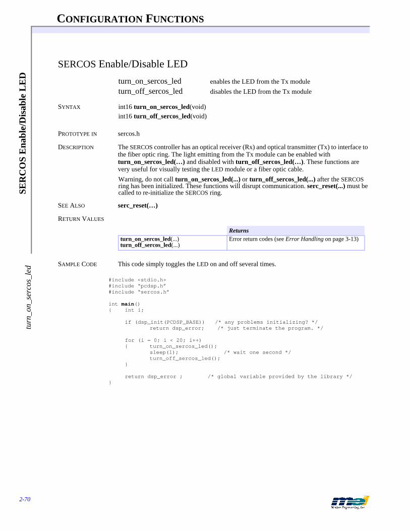
CONFIGURATION FUNCTIONS
2-70
SER
CO
S E
nabl
e/D
isab
le L
ED
turn
_on_
serc
os_l
ed
SERCOS Enable/Disable LED
turn_on_sercos_led enables the LED from the Tx moduleturn_off_sercos_led disables the LED from the Tx module
SYNTAX int16 turn_on_sercos_led(void)int16 turn_off_sercos_led(void)
PROTOTYPE IN sercos.h
DESCRIPTION The SERCOS controller has an optical receiver (Rx) and optical transmitter (Tx) to interface to the fiber optic ring. The light emitting from the Tx module can be enabled with turn_on_sercos_led(…) and disabled with turn_off_sercos_led(…). These functions are very useful for visually testing the LED module or a fiber optic cable.Warning, do not call turn_on_sercos_led(...) or turn_off_sercos_led(...) after the SERCOS ring has been initialized. These functions will disrupt communication. serc_reset(...) must be called to re-initialize the SERCOS ring.
SEE ALSO serc_reset(…)
RETURN VALUES
SAMPLE CODE This code simply toggles the LED on and off several times.
#include <stdio.h>#include “pcdsp.h”#include “sercos.h”
int main(){ int i;
if (dsp_init(PCDSP_BASE)) /* any problems initializing? */return dsp_error; /* just terminate the program. */
for (i = 0; i < 20; i++){ turn_on_sercos_led();
sleep(1); /* wait one second */turn_off_sercos_led();
}
return dsp_error ; /* global variable provided by the library */}
Returnsturn_on_sercos_led(...)turn_off_sercos_led(...)
Error return codes (see Error Handling on page 3-13)

CONFIGURATION FUNCTIONS
2-71
SER
CO
S Drive Status/R
eset M
ore #defines
SERCOS Drive Status/Reset
get_drive_status read the SERCOS node’s status wordreset_sercos_drive resets a SERCOS node
SYNTAX get_drive_status(int16 axis, int16 * status)reset_sercos_drive(int16 axis)
PROTOTYPE IN sercos.h
DESCRIPTION get_drive_status(…) reads an axis’ Drive Status Word directly from the controller. The con-troller axis’ status word is updated by the real-time cyclic data from IDN 135. The Drive Status Word contains the operation status bits (SERCOS specification):
serc_reset(...) will automatically map the following bits from the drive’s status word into the DSP’s dedicated I/O registers (for all drive_modes except USERMAP):
Every sample, the DSP examines the Dedicated I/O registers to determine if a controller excep-tion event should be triggered. For more information, also see
• Dedicated I/O (Inputs, page 3-56)• Exception Events (Axis State page 3-45, Axis Source page 3-46)• Event Recovery (page 3-54)• Home Config (Action page 2-32, Logic page 2-34)• Limit Config (Input Action page 2-37, Input Level page 2-39) • Amp Fault Config (Input page 2-41, Enable Output page 2-43)• Events (Stop page 3-48, Emergency Stop page 3-50, Abort page 3-52)
reset_sercos_drive(…) initiates drive procedure 99 and waits for completion. Procedure 99
Table 2-42 SERCOS Drive Status Word
Bit(s) Explanation
14, 15 Ready to Operate13 Drive Shutdown - Error in Class 1 Diagnostic (see IDN 11)12 Change bit for Class 2 Diagnostic (see IDN 12)11 Change bit for Class 3 Diagnostic (see IDN 13)10 Reserved
9, 8 Actual Operation Mode (IDNs 32, 33, 34, 35)7 Real-time status bit 2 (IDN 306)6 Real-time status bit 1 (IDN 304)5 Procedure command change bit
4, 3 Reserved2 Service Container Error (non-cyclic data)1 Busy (non-cyclic data)0 Amplifier Handshake (non-cyclic data)
Table 2-43 Drive Status Word Mapping to DSP Dedicated I/O Register
Bit Description DSP’s Dedicated I/O Register
13 Drive Shutdown - Error in Class 1 Diagnostic (see IDN 11) Amp Fault7 Real-time status bit 2 (IDN 306) Home6 Real-time status bit 1 (IDN 304) Pos and Neg Limit

CONFIGURATION FUNCTIONS
2-72
SER
CO
S D
rive
Sta
tus/
Res
etM
ore
#def
ines
clears the Class 1 Diagnostic (IDN 11), the Interface Status (IDN 14) and the Manufacturer Class 1 Diagnostic (IDN 129).
axis is the controller’s axis number assigned to a particular SERCOS node. The controller axis numbers are defined during SERCOS ring initialization with serc_reset(…). The valid range for axis is between 0 and 7.
SEE ALSO axis_state(...), axis_source(...), serc_reset(…), get_idn(...)
RETURN VALUES
SAMPLE CODE This code demonstrates how to read the Drive Status Word and reset a Class 1 error. Be sure to always initialize SERCOS communication with serc_reset(…) before invoking get_drive_status(…) or reset_sercos_drive(…):
#include <stdio.h>#include “pcdsp.h”#include “sercos.h”
#define CLASS_1_ERROR 0x2000 /* bit 13 */#define CLASS_2_ERROR 0x1000 /* bit 12 */#define AXIS 0
int main(){ int status;
int code;char string;
if (dsp_init(PCDSP_BASE)) /* any problems initializing? */return dsp_error; /* just terminate the program. */
get_drive_status(AXIS, &status);printf("\nDrive Status:0x%x", status);
if (status & CLASS_1_ERROR) { get_class_1_diag(AXIS, &code, string);
printf("\nClass 1:(0x%x) %s", code, string);
disable_amplifier(AXIS);reset_sercos_drive(AXIS);controller_run(AXIS);enable_amplifier(AXIS);
}
if (status & CLASS_2_ERROR) { get_class_2_diag(AXIS, &code, string);
printf("\nClass 2:(0x%x) %s", code, string);}
return dsp_error ; /* global variable provided by the library */}
Returnsget_drive_status(...)reset_sercos_drive(...)
Error return codes (see Error Handling on page 3-13)
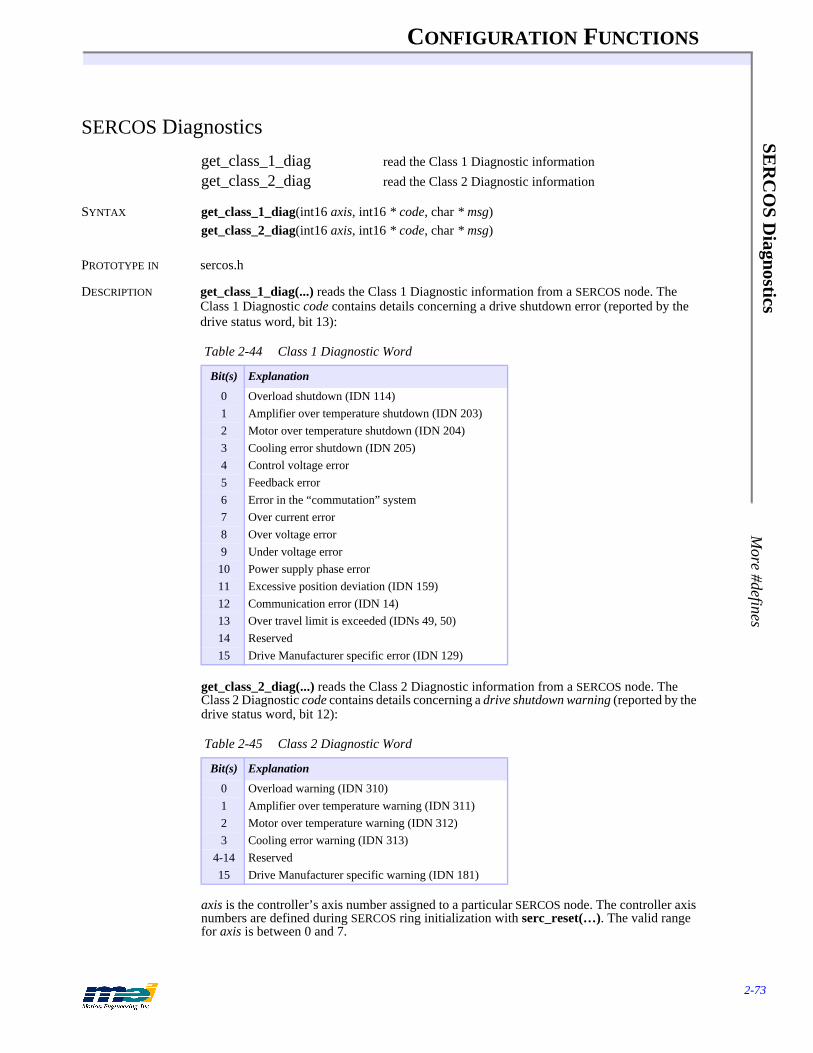
CONFIGURATION FUNCTIONS
2-73
SER
CO
S Diagnostics
More #defines
SERCOS Diagnostics
get_class_1_diag read the Class 1 Diagnostic informationget_class_2_diag read the Class 2 Diagnostic information
SYNTAX get_class_1_diag(int16 axis, int16 * code, char * msg)get_class_2_diag(int16 axis, int16 * code, char * msg)
PROTOTYPE IN sercos.h
DESCRIPTION get_class_1_diag(...) reads the Class 1 Diagnostic information from a SERCOS node. The Class 1 Diagnostic code contains details concerning a drive shutdown error (reported by the drive status word, bit 13):
get_class_2_diag(...) reads the Class 2 Diagnostic information from a SERCOS node. The Class 2 Diagnostic code contains details concerning a drive shutdown warning (reported by the drive status word, bit 12):
axis is the controller’s axis number assigned to a particular SERCOS node. The controller axis numbers are defined during SERCOS ring initialization with serc_reset(…). The valid range for axis is between 0 and 7.
Table 2-44 Class 1 Diagnostic Word
Bit(s) Explanation
0 Overload shutdown (IDN 114)1 Amplifier over temperature shutdown (IDN 203)2 Motor over temperature shutdown (IDN 204)3 Cooling error shutdown (IDN 205)4 Control voltage error5 Feedback error6 Error in the “commutation” system7 Over current error8 Over voltage error9 Under voltage error10 Power supply phase error11 Excessive position deviation (IDN 159)12 Communication error (IDN 14)13 Over travel limit is exceeded (IDNs 49, 50)14 Reserved15 Drive Manufacturer specific error (IDN 129)
Table 2-45 Class 2 Diagnostic Word
Bit(s) Explanation
0 Overload warning (IDN 310)1 Amplifier over temperature warning (IDN 311)2 Motor over temperature warning (IDN 312)3 Cooling error warning (IDN 313)
4-14 Reserved15 Drive Manufacturer specific warning (IDN 181)

CONFIGURATION FUNCTIONS
2-74
SER
CO
S D
iagn
osti
csM
ore
#def
ines
*msg is a pointer to a string that describes the shutdown or warning conditions. The string length is MAX_ERROR_LEN characters.
SEE ALSO get_drive_status(...), reset_sercos_drive(...), get_idn(...), get_idn_string(...), get_idn_attributes(...)
RETURN VALUES
SAMPLE CODE This code demonstrates how to read the Class 1 and Class 2 diagnostic information. Be sure to always initialize SERCOS communication with serc_reset(…) before invoking get_class_1_diag(…) or get_class_2_diag(…):
#include <stdio.h>#include “pcdsp.h”#include “sercos.h”#define AXIS 0
int main(){ int code;
char string;
if (dsp_init(PCDSP_BASE)) /* any problems initializing? */return dsp_error; /* just terminate the program. */
get_class_1_diag(AXIS, &code, string);printf("\nClass 1:(0x%x) %s", code, string);get_class_2_diag(AXIS, &code, string);printf("\nClass 2:(0x%x) %s", code, string);return dsp_error ; /* global variable provided by the library */
}
Returnsget_class_1_diag(...)get_class_2_diag(...)
Error return codes (see Error Handling on page 3-13)
OPERATION FUNCTIONS
3-1
CHAPTER 3 OPERATION FUNCTIONS
This chapter describes the medium-level functions used for motion operations, logically orga-nized into topics that support specific features. The function prototypes are in PCDSP.H. “Sample Code” sections are code fragments; they do not contain everything needed to compile and run.

OPERATION FUNCTIONS
3-2
Qui
ck L
ist
Quick List
Type Function Description
Initializationpage 3-8 dsp_init(controller_address) Software initialization
dsp_reset(void) Hardware resetInitialization with Environmental Variables
page 3-9 do_dsp(void) Initialize controller from shell environment variables
understand_dsp(* var) Reads DSP environment variabledsp_base DSP base address
PCI and Compact PCIInitialization
page 3-10 find_pci_dsp(*boards_found, *pci_addresses, *pci_interrupt)
Finds the address and IRQs of PCI/CPCI con-trollers on the bus
PCI and Compact PCIBoard Identification
page 3-11 dsp_get_id(board_addr, id_addr, *data) Reads the identification register dsp_set_id(board_addr, id_addr, data) Configures the identification register
Error Handlingpage 3-13 dsp_error Returns last error code variable
error_msg(code, * dst) Copies error message to bufferSingle Axis Point to Point Motion
page 3-17 start_move(axis, position, vel, accel) Begin a trapezoidal profile movemove(axis, position, vel, accel) Perform a trapezoidal profile movestart_r_move(axis, distance, vel, accel) Begin a relative trapezoidal profile mover_move(axis, distance, vel, accel) Perform a relative trapezoidal profile movestart_t_move(axis, position, vel, accel, decel) Begin a non-symmetrical trapezoidal profile
movet_move(axis, position, vel, accel, decel) Perform a non-symmetrical trapezoidal pro-
file movewait_for_done(axis) Wait for an axis to finish
Single-AxisS-Curve Profile Motion
page 3-19 start_s_move(axis, position, vel, accel, jerk) Begin an S-curve moves_move(axis, position, vel, accel, jerk) Perform an S-curve profile movestart_rs_move(axis, distance, vel, accel, jerk) Begin a relative S-curve movers_move(axis, distance, vel, accel, jerk) Perform a relative S-curve profile movestart_sprof_move(axis, position, vel, accel, jerk)
Begin an S-curve move
sprof_move(axis, position, vel, accel, jerk) Perform an S-curve profile moveSingle AxisParabolic Profile Motion
page 3-21 start_p_move(axis, final, vel, accel, jerk) Begin a parabolic profile movep_move(axis, final, vel, accel, jerk) Perform a parabolic profile move
Multi-Axis Point-to-Point Motion

OPERATION FUNCTIONS
3-3
Quick L
ist
page 3-22 start_move_all(length, * axes, * position, * vel, * accel)
Begin a multi-axis trapezoidal profile move
move_all(length, * axes, * position, * vel, * accel)
Perform a multi-axis trapezoidal profile move
wait_for_all(length, * axes) Wait for all axes to finishVelocity Move
page 3-23 v_move(axis, vel, accel) Accelerate an axis to a constant velocityCoordinated Axis Map
page 3-24 map_axes(n_axes, * map_array) Maps coordinated motion axes x, y, z......Start/End Coordinated Point List
page 3-25 start_point_list(void) Start an interpolated point listend_point_list(void) End an interpolated point listget_last_point(* x) Get last commanded point
Coordinated Motion Parameters
page 3-26 set_move_speed(speed) Set the vector velocity set_move_accel(accel) Set the vector acceleration
set_arc_division(degrees) Set the interpolation arc segment lengtharc_optimization(opt) Enable/Disable optimum acceleration calcu-
lations for arcsset_move_ratio(* ratio) Set the axis resolution ratios
Start/Stop Coordinated Motion
page 3-28 start_motion(void) Start coordinated motionstop_motion(void) Stop coordinated motionset_points(points) Set the number of points before motion startsall_done(void) Returns TRUE if motion is complete
Linear Coordinated Motion
page 3-29 move_2(x, y) 2-axis linear interpolated movemove_3(x, y, z) 3-axis linear interpolated movemove_4(x, y, z, w) 4-axis linear interpolated movemove_n(* x) n-axis linear interpolated moveadd_point(* x) Add a point to point list
Circular Coordinated Motion
page 3-29 arc_2(x_center, y_center, angle) 2-axis circular interpolated move add_arc(* center, angle, division) Add an arc to point listUser I/O During Coordinated Motion
page 3-31 set/reset_move_bit(bitNo) Turn on/off an output bit at the next pointchange_move_bit(bitNo, state) Update an output bit at the next pointset_move_output(value) Update 16 bits of user I/O (ports 0 & 1) at the
next pointCubic Spline Coordinated Motion
page 3-33 load_spline_motion(n_axes, * axis_map, n_points, * (* points_list), * g, * end_flag)
Download frames for an n-axis cubic spline motion
start_spline_motion(n_axes, * axis_map) Start a cubic spline coordinated motion
Type Function Description

OPERATION FUNCTIONS
3-4
Qui
ck L
ist Frame Buffer Mgmt
page 3-36 fifo_space(void) Returns the number of free frames left in the buffer
frames_to_execute(axis) Returns the number of frames left to execute for an axis
Position Controlpage 3-38 set/get_position(axis, position) Set or get current actual position
dsp_encoder(axis) Read 16 bit position directly from the encoderset/get_command(axis, position) Set or get current command positionset/get_last_command(axis, position) Set or get last command position valueget_error(axis, * error) Get current position error
Trajectory Controlpage 3-40 set/get_velocity(axis, vel) Set or get current command velocity
set/get_accel(axis, accel) Set or get current command accelerationset/get_jerk(axis, jerk) Set or get current command jerk
Motion Statuspage 3-42 in_sequence(axis) Returns TRUE during loading or execution of
framesin_motion(axis) Returns TRUE if command velocity is non-
zeroin_position(axis) Returns TRUE if axis is in-positionnegative_direction(axis) Returns TRUE if command velocity is nega-
tiveframes_left(axis) Returns TRUE if frames left for an axismotion_done(axis) Returns TRUE if !in_sequence, !in_motion,
!frames_leftaxis_done(axis) Returns TRUE if motion_done &&
in_positionAxis Status/State/Source
page 3-44 axis_status(axis) Read the axis status word & return it page 3-45 axis_state(axis) Read if an exception event has occurred & re-
turn status word page 3-46 axis_source(axis) Read the cause of an exception event & return
status wordStop Event
page 3-48 set_stop(axis) Generate a Stop Event on an axisset/get_stop_rate(axis, rate) Set or get deceleration rate for a Stop Eventset/get_boot_stop_rate(axis, rate) Set or get boot deceleration rate for a Stop
EventEmergency Stop Event
page 3-50 set_e_stop(axis) Generate an E-Stop Event on an axis set/get_e_stop_rate(axis, rate) Set or get deceleration rate for an E-Stop
Eventset/get_boot_e_stop_rate(axis, rate) Set or get boot deceleration rate for an E-Stop
Event Abort Event
page 3-52 controller_idle(axis) Generate an Abort Event on an axisdisable_amplifier(axis) Set the state of the amp enable output
Event Recovery
Type Function Description
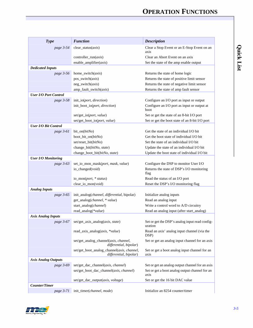
OPERATION FUNCTIONS
3-5
Quick L
ist
page 3-54 clear_status(axis) Clear a Stop Event or an E-Stop Event on an axis
controller_run(axis) Clear an Abort Event on an axisenable_amplifier(axis) Set the state of the amp enable output
Dedicated Inputspage 3-56 home_switch(axis) Returns the state of home logic
pos_switch(axis) Returns the state of positive limit sensorneg_switch(axis) Returns the state of negative limit sensoramp_fault_switch(axis) Returns the state of amp fault sensor
User I/O Port Controlpage 3-58 init_io(port, direction) Configure an I/O port as input or output
init_boot_io(port, direction) Configure an I/O port as input or output at boot
set/get_io(port, value) Set or get the state of an 8-bit I/O portset/get_boot_io(port, value) Set or get the boot state of an 8-bit I/O port
User I/O Bit Controlpage 3-61 bit_on(bitNo) Get the state of an individual I/O bit
boot_bit_on(bitNo) Get the boot state of individual I/O bitset/reset_bit(bitNo) Set the state of an individual I/O bitchange_bit(bitNo, state) Update the state of an individual I/O bitchange_boot_bit(bitNo, state) Update the boot state of individual I/O bit
User I/O Monitoringpage 3-63 set_io_mon_mask(port, mask, value) Configure the DSP to monitor User I/O
io_changed(void) Returns the state of DSP’s I/O monitoring flag
io_mon(port, * status) Read the status of an I/O portclear_io_mon(void) Reset the DSP’s I/O monitoring flag
Analog Inputspage 3-65 init_analog(channel, differential, bipolar) Initialize analog inputs
get_analog(channel, * value) Read an analog inputstart_analog(channel) Write a control word to A/D circuitryread_analog(*value) Read an analog input (after start_analog)
Axis Analog Inputspage 3-67 set/get_axis_analog(axis, state) Set or get the DSP’s analog input read config-
urationread_axis_analog(axis, *value) Read an axis’ analog input channel (via the
DSP)set/get_analog_channel(axis, channel,
differential, bipolar)Set or get an analog input channel for an axis
set/get_boot_analog_channel(axis, channel, differential, bipolar)
Set or get a boot analog input channel for an axis
Axis Analog Outputspage 3-69 set/get_dac_channel(axis, channel) Set or get an analog output channel for an axis
set/get_boot_dac_channel(axis, channel) Set or get a boot analog output channel for an axis
set/get_dac_output(axis, voltage) Set or get the 16 bit DAC valueCounter/Timer
page 3-71 init_timer(channel, mode) Initialize an 8254 counter/timer
Type Function Description

OPERATION FUNCTIONS
3-6
Qui
ck L
ist set/get_timer(channel, t) Set or get a counter/timer value
Master/Slave Operationpage 3-73 mei_link(master, slave, ratio, source) Configure two axes for master/slave opera-
tionendlink(slave) Discontinue master/slave operation
Master/Cam Operationpage 3-75 set_cam(master_axis, cam_axis, cam,
source)Configure two axes for master/cam operation
set_boot_cam(master_axis, cam_axis, cam, source)
Configure two axes for boot master/cam op-eration
Feed Speed Overridepage 3-77 dsp_feed_rate(feed_rate) Change all axes running speed from 0% to
200%axis_feed_rate(axis, feed_rate) Change an axis’ running speed from 0% to
200%Position Latching
page 3-79 arm_latch(enable) Enables the DSP interrupt and resets a ready flag
latch_status(void) Returns FALSE until positions latch is com-plete
get_latched_position(axis, * position) Returns the latched position of an axislatch(void) Generate a position latch from software
On-Board Joggingpage 3-81 jog_axis(axis, jog_channel, c, d, m1, m2,
enable)Configure on board analog input jogging for one axis
Multiple Controllerspage 3-83 m_setup(boards, * controller_addresses) Initialize pointers to access multiple control-
lersm_board(board_number) Switch pointers to access a particular boardm_axis(actual_axis) Switch pointers to access a particular axis
Trajectory Framespage 3-85 dsp_dwell(axis, duration) Delay execution of next frame
dsp_position(axis, position, duration) Update command position and delay next frame
dsp_velocity(axis, vel, duration) Update velocity and delay next framedsp_accel(axis, accel, duration) Update accel and delay next framedsp_jerk(axis, jerk, duration) Update jerk and delay next framedsp_end_sequence(axis) Clear the in_sequence status bit
I/O Framespage 3-87 dsp_io_frame(axis, port, ormask, andmask) Set the state of an 8-bit I/O port
dsp_io_trigger(axis, bit, state) Delay next frame until bit level changes to state
dsp_io_trigger_mask(axis, port, mask, state) Delay next frame until bit level(s) change to state
Type Function Description
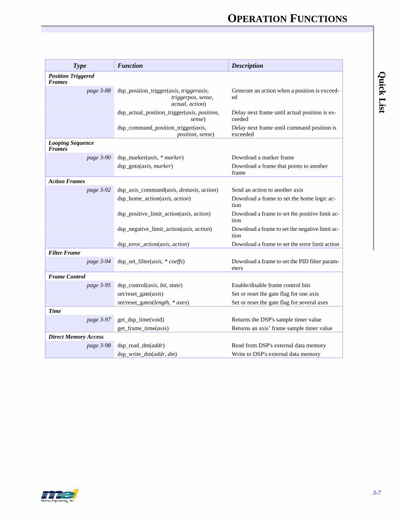
OPERATION FUNCTIONS
3-7
Quick L
ist
Position Triggered Frames
page 3-88 dsp_position_trigger(axis, triggeraxis, triggerpos, sense, actual, action)
Generate an action when a position is exceed-ed
dsp_actual_position_trigger(axis, position, sense)
Delay next frame until actual position is ex-ceeded
dsp_command_position_trigger(axis, position, sense)
Delay next frame until command position is exceeded
Looping Sequence Frames
page 3-90 dsp_marker(axis, * marker) Download a marker framedsp_goto(axis, marker) Download a frame that points to another
frameAction Frames
page 3-92 dsp_axis_command(axis, destaxis, action) Send an action to another axisdsp_home_action(axis, action) Download a frame to set the home logic ac-
tiondsp_positive_limit_action(axis, action) Download a frame to set the positive limit ac-
tiondsp_negative_limit_action(axis, action) Download a frame to set the negative limit ac-
tiondsp_error_action(axis, action) Download a frame to set the error limit action
Filter Framepage 3-94 dsp_set_filter(axis, * coeffs) Download a frame to set the PID filter param-
etersFrame Control
page 3-95 dsp_control(axis, bit, state) Enable/disable frame control bitsset/reset_gate(axis) Set or reset the gate flag for one axisset/reset_gates(length, * axes) Set or reset the gate flag for several axes
Timepage 3-97 get_dsp_time(void) Returns the DSP's sample timer value
get_frame_time(axis) Returns an axis’ frame sample timer valueDirect Memory Access
page 3-98 dsp_read_dm(addr) Read from DSP's external data memorydsp_write_dm(addr, dm) Write to DSP's external data memory
Type Function Description

OPERATION FUNCTIONS
3-8
Init
ializ
atio
nds
p_in
it
Initialization
dsp_init set controller's I/O base address for all other software callsdsp_reset reset the controller to its power-up state
SYNTAX int16 dsp_init(int16 controller_address)int16 dsp_reset(void)
PROTOTYPE IN pcdsp.h
DESCRIPTION dsp_init(...) sets the controller base address and reads other configuration data from the DSP controller. Every program must call dsp_init(...) before any other function can be used. Make sure to check the error code. The controller_address specifies the I/O base address of the con-troller. The value of controller_address must match the switch settings on the controller (see the Installation Manual). The identifier PCDSP_BASE is defined in PCDSP.H as 0x300; the fac-tory default base address.dsp_reset(...) causes a power-up reset of the DSP controller. The software and hardware con-figurations are re-read from boot memory, the command and actual positions are reset, the amp enable output is disabled, user I/O is reconfigured, etc., dsp_reset(...) also calls dsp_init(...) so make sure to check the error code. A hardware reset causes the DSP to release control of the axes and I/O for a few milliseconds which may cause motors to jump.
SERCOS If the SERCOS communication ring has been initialized with serc_reset(…), then dsp_reset(…) will simply return error code 114 (DSP_SERCOS_RESET).
SEE ALSO do_dsp(...), m_setup(…), map_axes(...)
RETURN VALUES
SAMPLE CODE This sample code simply initializes the DSP controller and prints the error message. All pro-grams must call dsp_init(...) to initialize communication with the controller:
# include "pcdsp.h"
int main(){
int16 error;char buffer[MAX_ERROR_LEN];
error = dsp_init(PCDSP_BASE); /* initialize the controller */error_msg(error, buffer);printf(“\nValue: %d Message: %s”, error, buffer);
return dsp_error; /* global variable provided by the library */}
NOTES Often times we have seen code that calls dsp_reset(...) before dsp_init(...). Don't do this! Make sure you always call dsp_init(..) first. dsp_init(...) only initializes the soft-ware and has no effect on the current state of the controller. Most applications do not need to call dsp_reset(...).
Returnsdsp_init(...)dsp_reset(...)
Error return codes (see Error Handling on page 3-13)

OPERATION FUNCTIONS
3-9
Initialization with E
nvironment V
ariables do_dsp
Initialization with Environment Variables
do_dsp initialize controller with shell environment variablesunderstand_dsp reads DSP environment variabledsp_base global variable representing the controller I/O address
SYNTAX int16 do_dsp(void)int16 understand_dsp(char * var)int16 dsp_base
PROTOTYPE IN pcdsp.h
DESCRIPTION These functions know how to understand an environment variable called DSP, and are provid-ed to allow easy access to external parameters in your program.understand_dsp(...) interprets the environment variable DSP. Currently, DSP supports a sin-gle parameter called BASE, which is used to specify the base I/O address of the controller. If BASE is specified, then dsp_base is set to the value specified.
For example, if set DSP=base:0x280' is executed at the DOS prompt, and later understand_dsp(...) is called, then it will assign dsp_base with an address of 0x280. By de-fault, dsp_base is assigned PCDSP_BASE.
do_dsp(...) executes understand_dsp(...). It then calls dsp_init(...) with dsp_base as the ad-dress. do_dsp(...) returns the error code given by dsp_init(...).
RETURN VALUES
SAMPLE CODE This sample code simply initializes the DSP controller and prints the error message. The func-tion do_dsp(...) initializes the controller with the address set by the environment variable dsp_base. If the environment variable has not been set then the controller will be initialized us-ing the default address PCDSP_BASE:
# include "pcdsp.h"
int main(){
int16 error;char buffer[MAX_ERROR_LEN];
error = do_dsp();error_msg(error, buffer);printf(“\nValue: %d Message: %s”, error, buffer);return dsp_error; /* global variable provided by the library*/
}
NOTES The environment variable is very useful when programs need to access DSP controllers at dif-ferent I/O addresses. SETUP.EXE and CONFIG.EXE use do_dsp(...) to initialize the DSP con-troller.
Returnsdo_dsp(...)understand_dsp(...)
Error return codes (see Error Handling on page 3-13)

OPERATION FUNCTIONS
3-10
PC
I an
d C
ompa
ctP
CI
Init
ializ
atio
nfin
d_pc
i_ds
p
PCI and CompactPCI Initialization
find_pci_dsp finds the address and IRQs of all MEI PCI/CPCI controllers on the bus
SYNTAX int16 find_pci_dsp(int16 * boards_found, int16 * pci_addresses, int16 * pci_interrupt)
PROTOTYPE IN pcdsp.h
DESCRIPTION Since the BIOS dynamically assigns PCI and CPCI devices their addresses and IRQ resources at boot up, the function find_pci_dsp(...) provides the user with the number of PCI and CPCI controllers found in the system, boards_found, as well as their IO address, pci_address, and IRQ, pci_interrupt. This function is valid under DOS, Windows 95/98, Windows NT and Vx-Works 5.3.1.find_pci_dsp(...) should be used in conjunction with dsp_init(...) to properly locate and ini-tialize communication with a PCI bus motion controller.
The define MAX_PCI_BOARDS has been added to the library to allocate the maximum num-ber of PCI devices in a system to be 20.
RETURN VALUES dsp_init(...), do_dsp(...), m_setup(...), map_axes(...)
RETURN VALUES See Error Handling on page 3-13 for the error return codes
SAMPLE CODE This sample code calls the find_pci_dsp(...) function to return the resources of any PCI con-trollers found on the bus.
# include <stdio.h># include <stdlib.h># include “pcdsp.h”
int main(){
int16 count, boardsfound, addrs[MAX_PCI_BOARDS],irqs[MAX_PCI_BOARDS];
printf(“Searching for PCI bus DSP boards...\n”);find_pci_dsp(&boardsfound, addrs, irqs);if(boardsfound){
printf(“ %d MEI Controller%s found:\n, boardsfound, boardsfound > 1?”s” :””);for(count = 0; count < boardsfound ; count++){
printf(“ Board%d at I/O address: 0x%X using IRQ: %d\n”, count, addrs[count] & 0xFFFF, irqs[count]);
}}else
printf(“ No PCI motion controllers found in system.\n”);
printf(“\n”);return 0 ;
}
NOTES The find_pci_dsp(...) function only returns the address and IRQs of all PCI controllers found on the bus. dsp_init(...) will still need to be used to initialize communication with the control-ler. Please see the Initialization section in this manual for further usage instructions.

OPERATION FUNCTIONS
3-11
PC
I and Com
pactPC
I Board Identification
dsp_get_id
PCI and CompactPCI Board Identification
dsp_get_id reads the identification register on the MEI controllerdsp_set_id configures the indentification register on the MEI controller
SYNTAX int16 dsp_get_id(int16 board_addr, unsigned16 id_addr, unsigned32 * data)int16 dsp_set_id(int16 board_addr, unsigned16 id_addr, unsigned 32 data)
PROTOTYPE IN pcdsp.h
DESCRIPTION Two functions are used to support the Board Identification feature implemented on PCI and CPCI DSP controllers under a 32-bit Microsoft environment only. MEI has provided the user with two 32-bit DWORD registers to store board identification information or general user in-formation. The functions dsp_get_id(...) and dsp_set_id(...) allow the user to read and write to the DSP_BOARD_ID and DSP_USER_ID 32-bit registers, where board_addr is the base address of the controller, id_addr is the desired identification address and data is the desired identification value. MEI also provides READ ONLY data registers for reading other board information:
RETURN VALUES dsp_init(...), do_dsp(...), m_setup(...), map_axes(...)
RETURN VALUES See Error Handling on page 3-13 for the error return codes
SAMPLE CODE This sample code simply retrieves the address of a PCI/DSP or CPCI/DSP controller and sets a specific Board and User ID to identify the controller by.
# include <stdio.h># include <stdlib.h># include “pcdsp.h”
int main(){
int16 count, boardsfound, addrs[MAX_PCI_BOARDS],irqs[MAX_PCI_BOARDS];unsigned32 val;
printf(“Searching for PCI bus DSP boards...\n”);find_pci_dsp(&boardsfound, addrs, irqs);if(boardsfound){
printf(“ %d MEI Controller%s found:\n, boardsfound, boardsfound >1?”s”:””);for(count = 0; count < boardsfound ; count++){
printf(“ \tBoard%d at I/O address: 0x%X using IRQ: %d\n”, count, addrs[count] & 0xFFFF, irqs[count]);
dsp_set_id(addrs[count], DSP_BOARD_ID, 0xBEEFCAFE);dsp_set_id(addrs[count], DSP_USER_ID, 0xCAFEBEEF);
Identification Address Value Register Definition User Read or Write
DSP_BOARD_ID 0x7C Board Identification Number User Read/Write
DSP_USER_ID 0x78 User Identification Number User Read/Write
DSP_SERIAL_ID 0x74 Controller Serial Number* User Read OnlyDSP_PART_ID 0x70 Controller Part Number* User Read Only
DSP_REV_ID 0x6C Controller Revision Identification* User Read OnlyDSP_FEATURE_ID 0x68 Special Feature Identification* User Read Only
*Identification information not yet implemented on the controllers at time of release - Nov 1999.
OPERATION FUNCTIONS
3-12
PC
I an
d C
ompa
ctP
CI
Boa
rd I
dent
ific
atio
nds
p_ge
t_id
dsp_get_id(addrs[count], DSP_BOARD_ID, &val);printf(“Board ID read: 0x%8X\n”, val);
dsp_get_id(addrs[count], DSP_USER_ID, &val);printf(“User ID read: 0x%8X\n”, val);
}}else
printf(“ No PCI motion controllers found in system.\n”);
printf(“\n”);return 0 ;}

OPERATION FUNCTIONS
3-13
Error H
andling dsp_error
Error Handling
dsp_error last error code global variableerror_msg get error message
SYNTAX extern int16 dsp_errorint16 error_msg(int16 code, char * dst)
PROTOTYPE IN pcdsp.h
DESCRIPTION Most functions return an integer error code. The error code indicates the successful or unsuc-cessful execution of a function. Non-zero return values are errors. The global variable dsp_error is used to hold the most recent error code. The function error_msg(...) copies an ASCII description of the error corresponding to code into the character array pointed to by dst. This character array must be able to hold at least MAX_ERROR_LEN characters.PCDSP.H defines these identifiers for each error code. See the next table.
SAMPLE CODE This code prints an error message if dsp_init(...) fails. This is recommended as a motion pro-gram's typical initialization:
# include "pcdsp.h"
int main(){
int16 error;char buffer[MAX_ERROR_LEN];
error = dsp_init(PCDSP_BASE);if (error){ error_msg(error, buffer);
printf(“\nValue: %d Message: %s”, error, buffer);}return dsp_error; /* global variable provided by the library */
}
RETURN VALUES
NOTES Make sure that you always check the error message when dsp_init(...) is called. This function is the most likely to fail. It is a good idea to check the error codes returned by all of functions. The error codes were created to help programmers catch programming mistakes and hardware failures.
Returnsdsp_error Value (Last error code variable)error_msg(...) Error return codes (see Error Handling on page 3-13)
Table 3-1 Error Codes
#define Value Description
DSP_OK 0 This error code indicates successful completion of the last function.
DSP_NOT_INITIALIZED 1 dsp_init(...) must be called to initialize library static data. This error is returned if this static initialization hasn't been performed.
DSP_NOT_FOUND 2 dsp_init(...) wasn't able to find the DSP controller at the given I/O base address.

OPERATION FUNCTIONS
3-14
Err
or H
andl
ing
dsp_
erro
r
DSP_INVALID_AXIS 3 Any function taking an axis parameter can return this er-ror code, indicating reference to a non-existent axis.
DSP_ILLEGAL_ANALOG 4 Some of the DSP Series controllers have eight analog in-puts, numbered 0 to 7. This error indicates a reference to a non-existent channel.
DSP_ILLEGAL_IO 5 The DSP Series controllers have up to 6 User I/O ports. Any function taking a port parameter can return this code, indicating reference to a non-existent User I/O port.
DSP_OUT_OF_MEMORY 6
DSP_FRAME_UNALLOCATED 7 These are internal library error messages, and should nev-er be seen at higher levels. If you receive one of these messages, please contact us. They indicate problems passing information to the DSP controller.
DSP_ILLEGAL_PARAMETER 8 A move with zero acceleration, velocity, or jerk is consid-ered illegal.
DSP_ILLEGAL_CONVERSION 9 When either the Counts per Distance or Seconds per Pe-riod conversion factors are zero, any function using posi-tions, velocities, or accelerations can return this error.
DSP_FRAME_NOT_CONNECTED
10 This is an internal library error message for debugging purposes and should never be seen at higher levels.
DSP_FIRMWARE_VERSION 11 The firmware loaded from the boot memory (into the DSP) and the C function libraries have version numbers. This error message occurs when the firmware and library versions do not match or other fundamental configuration problems exist.
DSP_ILLEGAL_TIMER 12 The 8254 timer is configured using the function init_timer(...). This error message occurs when an in-valid timer number is chosen with init_timer(...), set_timer(...) or get_timer(...).
DSP_STRUCTURE_SIZE 13 Indicates problems after porting the library to another op-erating system or compiler with different integer sizes. Also see Compiling under Unsupported Operating Sys-tems, page 1-5.
DSP_TIMEOUT_ERROR 14 Indicates that the DSP controller is not responding.
DSP_RESOURCE_IN_USE 15 The function libraries have a few global resources. This error message occurs when a resource is already in use. Those functions that are not re-entrant will return this code if re-entered.
DSP_CHECKSUM 16 The dsp_init(...) function checks the boot memory of the DSP controller. This error message indicates the boot memory has been corrupted or there are bus communica-tion problems.
DSP_CLEAR_STATUS 17 clear_status(...) can't be performed while in_sequence(...) is TRUE. This message indicates that the event was not cleared.
DSP_NO_MAP 18 map_axes(...) was not called before using coordinated motion.
DSP_NO_ROOM 19 This error indicates that the frame buffer is full. The frame buffer has a capacity of 600 frames.
DSP_BAD_FIRMWARE_FILE 20 This error indicates that the firmware file cannot be opened or is corrupt.
DSP_ILLEGAL_ENCODER_CHANNEL
21 Encoder channel number is out of range.
DSP_FUNCTION_NOT_AVAILABLE
22 This function is not supported in this library version.
Table 3-1 Error Codes
#define Value Description

OPERATION FUNCTIONS
3-15
Error H
andling dsp_error
DSP_NO_EXTERNAL_BUFFER 23 Optional host CPU FIFO frame buffer is full or not avail-able.
DSP_NT_DRIVER 24 The DSPIO device driver for Windows NT support has not been installed properly.
DSP_FUNCTION_NOT_APPLICABLE
25 This function is not applicable to the current controller configuration.
DSP_NO_DISTANCE 26 A move with zero distance was commanded.
DSP_FIRMWARE_CHECKSUM 27 The firmware buffer checksum value is not valid.
DSP_FEATURE_NOT_SUPPORTED 28 The requested firmware is not supported by the current software/hardware.
DSP_ENVIRONMENT_NOT_SUPPORTED
29 The requested function is not supported by current com-piler or operating system.
DSP_SERCOS_SLAVE_ERROR 100 General failure of a SERCOS slave device. This error oc-curs when the slave is not responding.
DSP_SERCOS_INVALID_PARAM
101 SERCOS parameter out of range.
DSP_SERCOS_DISTORTED 102 Data transmitted/received on the SERCOS loop is distort-ed.
DSP_SERCOS_LOOP_OPEN 103 SERCOS fiber optic ring is not closed.
DSP_SERCOS_EARLY 104 Master Sync Telegram was sent too early
DSP_SERCOS_LATE 105 Master Sync Telegram was sent too late.
DSP_SERCOS_MST_MISSING 106 Master Sync Telegram was not sent.
DSP_SERCOS_DRIVE_INIT 107 SERCOS drive(s) were not found.
DSP_SERCOS_INVALID_DRIVE_TYPE
108 SERCOS drive mode is not supported by the drive.
DSP_SERCOS_INVALID_DRIVE_NUMBER
109 Number of SERCOS drives is out of range.
DSP_SERCOS_INVALID_DRIVE_ADDR
110 SERCOS drive address is out of range.
DSP_SERCOS_DUPLICATE_DRIVE_ADDR
111 SERCOS drive address is already in use by another drive.
DSP_SERCOS_PROC_FAILURE 112 SERCOS drive failed to execute a procedure.
DSP_SERCOS_AXIS_ASSIGNMENT
113 Axis number has not been assigned to a SERCOS drive.
DSP_SERCOS_RESET 114 Returned by dsp_reset(...) when used with a SERCOS controller. Use serc_reset(...) instead.
DSP_SERCOS_VARIABLE_READ
115 SERCOS IDN value is a variable length string. Use the function get_idn_string(...) instead.
DSP_SERCOS_INVALID_IDN_AT
116 SERCOS IDN cannot be placed in the user configurable portion of the Amplifier Telegram.
DSP_SERCOS_INVALID_IDN_MDT
117 SERCOS IDN cannot be placed in the user configurable portion of the Master Data Telegram.
DSP_SERCOS_127_FAILURE 118 SERCOS drive failed to execute procedure 127. Loop can-not advance to phase 3.
DSP_SERCOS_128_FAILURE 119 SERCOS drive failed to execute procedure 128. Loop can-not advance to phase 4.
DSP_SERCOS_IDN_NOT_AVAILABLE
120 SERCOS drive does not support the specified IDN.
DSP_SERCOS_NO_CHANNEL 121 SERCOS Service channel is not available.
Table 3-1 Error Codes
#define Value Description
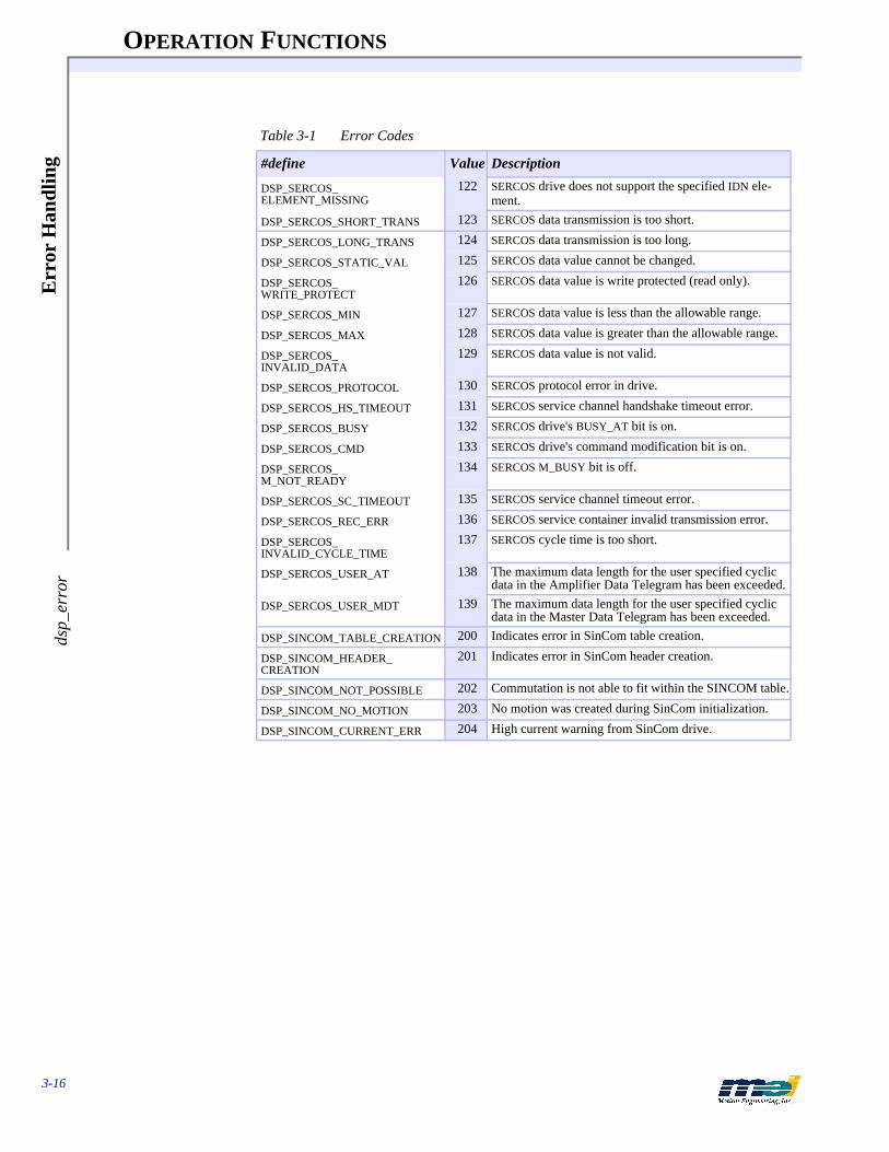
OPERATION FUNCTIONS
3-16
Err
or H
andl
ing
dsp_
erro
r
DSP_SERCOS_ELEMENT_MISSING
122 SERCOS drive does not support the specified IDN ele-ment.
DSP_SERCOS_SHORT_TRANS 123 SERCOS data transmission is too short.
DSP_SERCOS_LONG_TRANS 124 SERCOS data transmission is too long.
DSP_SERCOS_STATIC_VAL 125 SERCOS data value cannot be changed.
DSP_SERCOS_WRITE_PROTECT
126 SERCOS data value is write protected (read only).
DSP_SERCOS_MIN 127 SERCOS data value is less than the allowable range.
DSP_SERCOS_MAX 128 SERCOS data value is greater than the allowable range.
DSP_SERCOS_INVALID_DATA
129 SERCOS data value is not valid.
DSP_SERCOS_PROTOCOL 130 SERCOS protocol error in drive.
DSP_SERCOS_HS_TIMEOUT 131 SERCOS service channel handshake timeout error.
DSP_SERCOS_BUSY 132 SERCOS drive's BUSY_AT bit is on.
DSP_SERCOS_CMD 133 SERCOS drive's command modification bit is on.
DSP_SERCOS_M_NOT_READY
134 SERCOS M_BUSY bit is off.
DSP_SERCOS_SC_TIMEOUT 135 SERCOS service channel timeout error.
DSP_SERCOS_REC_ERR 136 SERCOS service container invalid transmission error.
DSP_SERCOS_INVALID_CYCLE_TIME
137 SERCOS cycle time is too short.
DSP_SERCOS_USER_AT 138 The maximum data length for the user specified cyclic data in the Amplifier Data Telegram has been exceeded.
DSP_SERCOS_USER_MDT 139 The maximum data length for the user specified cyclic data in the Master Data Telegram has been exceeded.
DSP_SINCOM_TABLE_CREATION 200 Indicates error in SinCom table creation.
DSP_SINCOM_HEADER_CREATION
201 Indicates error in SinCom header creation.
DSP_SINCOM_NOT_POSSIBLE 202 Commutation is not able to fit within the SINCOM table.
DSP_SINCOM_NO_MOTION 203 No motion was created during SinCom initialization.
DSP_SINCOM_CURRENT_ERR 204 High current warning from SinCom drive.
Table 3-1 Error Codes
#define Value Description
OPERATION FUNCTIONS
3-17
Single Axis P
oint-to-Point M
otion start_m
ove
Single Axis Point-to-Point Motion
start_move begin a trapezoidal profile motion sequencemove begin a trapezoidal motion sequence and wait for comple-
tionstart_r_move begin a relative trapezoidal profile motion sequencer_move begin a relative trapezoidal profile motion sequence and
wait for completionstart_t_move begin a non-symmetrical trapezoidal profile motion se-
quencet_move begin a non-symmetrical trapezoidal motion sequence and
wait for completionwait_for_done wait for the current sequence to complete
SYNTAX int16 start_move(int16 axis, double position, double velocity, double acceleration)int16 move(int16 axis, double position, double velocity, double acceleration)int16 start_r_move(int16 axis, double distance, double velocity, double acceleration)int16 r_move(int16 axis, double distance, double velocity, double acceleration)
int16 start_t_move(int16 axis, double position, double velocity, double acceleration, double decel)int16 t_move(int16 axis, double position, double velocity, double acceleration, double decel)int16 wait_for_done(int16 axis)
PROTOTYPE IN pcdsp.h
DESCRIPTION start_move(...) causes the axis to accelerate, slew at constant velocity, and decelerate to a stop at the specified absolute position, immediately returning control to the program. The accelera-tion rate is equal to the deceleration rate. move(...) starts an absolute coordinate move and waits for completion.start_r_move(...) causes the axis to accelerate, slew at constant velocity, and decelerate to a stop at the relative distance, immediately returning control to the program. The acceleration rate is equal to the deceleration rate. r_move(...) starts a relative move and waits for comple-tion.
start_t_move(...) causes the axis to accelerate, slew at constant velocity, and decelerate to a stop at the absolute position, immediately returning control to the program. t_move(...) starts an absolute coordinate move and waits for completion.
If the move distance is too short to reach the specified velocity the controller will accelerate for the first half of the distance and decelerate for the second half (triangular profile). wait_for_done(...) waits for the motion to complete.
EXECUTION These functions download 5 frames to the controller: acceleration, velocity, deceleration, com-mand position, and dwell. The start_move(...), move(...), start_t_move(...) and t_move(...) functions may also require one sample before the frames are downloaded to read the command position.

OPERATION FUNCTIONS
3-18
Sing
le A
xis
Poi
nt-t
o-P
oint
Mot
ion
star
t_m
ove
RETURN VALUES
SEE ALSO motion_done(...), axis_done(...)
Figure 3-1 Trapezoidal Profile Motion
SAMPLE CODE This program continuously moves axis 0 between two points.# include "pcdsp.h"
# define P1 1000000.0# define P2 0.0
int main(){
int16 e, f = 0;
e = dsp_init(PCDSP_BASE),
while (!e){ if(f)
e = move(0, P1, 8000, 32000); /* trapezoidal profile motion */else
e = move(0, P2, 8000, 32000);f = !f;
}return e;
}
NOTES The relative move functions start_r_move(...) and r_move(...) take about one sample period (default = 0.8 milliseconds) less time to execute than start_move(...) and move(...). Since, the relative move functions calculate the motion profile in terms of velocity, acceleration, and time, they don't need to get the current command position. The single axis trapezoidal profile motion functions guarantee that the final command position is equal to the position parameter speci-fied.
If the move is a trapezoidal profile, then the acceleration time = Velocity/Acceleration. If the move is a triangular profile, then the acceleration time = SQUARE ROOT (Distance/Accel-eration).
Returnsstart_move(...)move(...)start_r_move(...)r_move(...)start_t_move(...)t_move(...)wait_for_done(...)
Error return codes (see Error Handling on page 3-13)
Deceleration
Slew
Accele
ration
TIME
VE
LO
CIT
Y

OPERATION FUNCTIONS
3-19
Single-Axis S-C
urve Profile M
otion start_s_m
ove
Single-Axis S-Curve Profile Motion
start_s_move begin a S-curve profile motion sequences_move begin a S-curve profile motion sequence and wait for it to
completestart_rs_move begin a relative S-curve profile motion sequencers_move begin a relative S-curve profile motion sequence and wait
for it to completestart_sprof_move begin a S-curve profile motion sequencesprof_move begin a S-curve profile motion sequence and wait for it to
complete
SYNTAX int16 start_s_move(int16 axis, double position, double velocity, double acceleration, double jerk)int16 s_move(int16 axis, double position, double velocity, double acceleration, double jerk)int16 start_rs_move(int16 axis, double dist, double velocity, double acceleration, double jerk)int16 rs_move(int16 axis, double dist, double velocity, double acceleration, double jerk)
int16 start_sprof_move(int16 axis, double position, double velocity, double acceleration, double jerk)int16 sprof_move(int16 axis, double position, double velocity, double acceleration, double jerk)
PROTOTYPE IN pcdsp.h
DESCRIPTION start_s_move(...) causes the axis to accelerate with S-curve acceleration, slew at constant ve-locity, and decelerate to a stop at the specified absolute position, immediately returning control to the program. The acceleration profile is equal to the deceleration profile. s_move(...) starts an absolute S-curve profile motion and waits for completion.start_rs_move(...) causes the axis to accelerate with S-curve acceleration, slew at constant ve-locity, and decelerate to a stop at the specified relative distance, immediately returning control to the program. The acceleration profile is equal to the deceleration profile. rs_move(...) starts a relative S-curve profile motion and waits for completion.
S-curve acceleration profiles are useful for both stepper and servo motors. The smooth transi-tions between the start of the acceleration ramp and the transition to the constant velocity pro-duce less wear and tear than a trapezoidal profile motion. The smoother performance increases the life of the motors and mechanics of a system.
Figure 3-2 S-Curve Profile Motion
Deceleration
Slew
Acceleration
TIME
VE
LO
CIT
Y
Jerk
Jerk Jerk
Jerk

OPERATION FUNCTIONS
3-20
Sing
le-A
xis
S-C
urve
Pro
file
Mot
ion
star
t_s_
mov
e
The S-curve profile motion functions were designed to always produce smooth motion. Certain combinations of parameters however, may not reach the command velocity, may cause longer than expected move times or may cause a slight bump at the end of the motion.
If the acceleration and jerk parameters combined with the final position don't allow an axis to reach the maximum velocity, then the acceleration is decreased. This means that with moves that don't reach maximum velocity, actually decreasing the maximum velocity may allow the axis to run faster.
If the following guidelines are followed, then the motion will be accurate, smooth, and the mo-tion time will be as expected:
X = move distance, Vel = velocity, Acc = acceleration, J = jerk
1) Vel/Acc > Acc/J if (Vel/Acc < Acc/J) then (Vel/Acc = Acc/J)
2) X/Vel > Vel/Acc + Acc/J if (X/Vel < (Vel/Acc + Acc/J)) then (X/Vel = Acc/J + Vel/Acc)
Each individual time component can be calculated by:
Acc/J = time for each jerk portion
Vel/Acc - Acc/J = time for each acceleration portion
X/Vel - Vel/Acc - Acc/J = time for the constant velocity
The total time to complete the move can be calculated by:
Time = Acc/J + Vel/Acc + X/Vel
start_sprof_move(…) and sprof_move(…) use a different algorithm to generate the S-curve motion profiles than start_s_move(…) and s_move(…). The “sprof” algorithm explicitly cal-culates the jerk, acceleration, and velocity times. Based on the move parameters, the algorithm reduces the velocity time first and then reduces the acceleration time. The algorithm guarantees a continuous profile ending at the final position specified.
The guidelines listed above are not required for start_sprof_move(…) or sprof_move(…).
EXECUTION These functions require 1 sample to read the command position and then download 9 frames to the controller: positive jerk, acceleration, negative jerk, velocity, negative jerk, deceleration, positive jerk, command position and dwell.
RETURN VALUES
SEE ALSO motion_done(...), axis_done(...)
NOTES Consider using S-curve motion when moving liquids, high inertial loads, or other such systems that are usually under-powered.
Returnsstart_s_move(...)s_move(...)start_rs_move(...)rs_move(...)start_sprof_move(...)sprof_move(...)
Error return codes (see Error Handling on page 3-13)
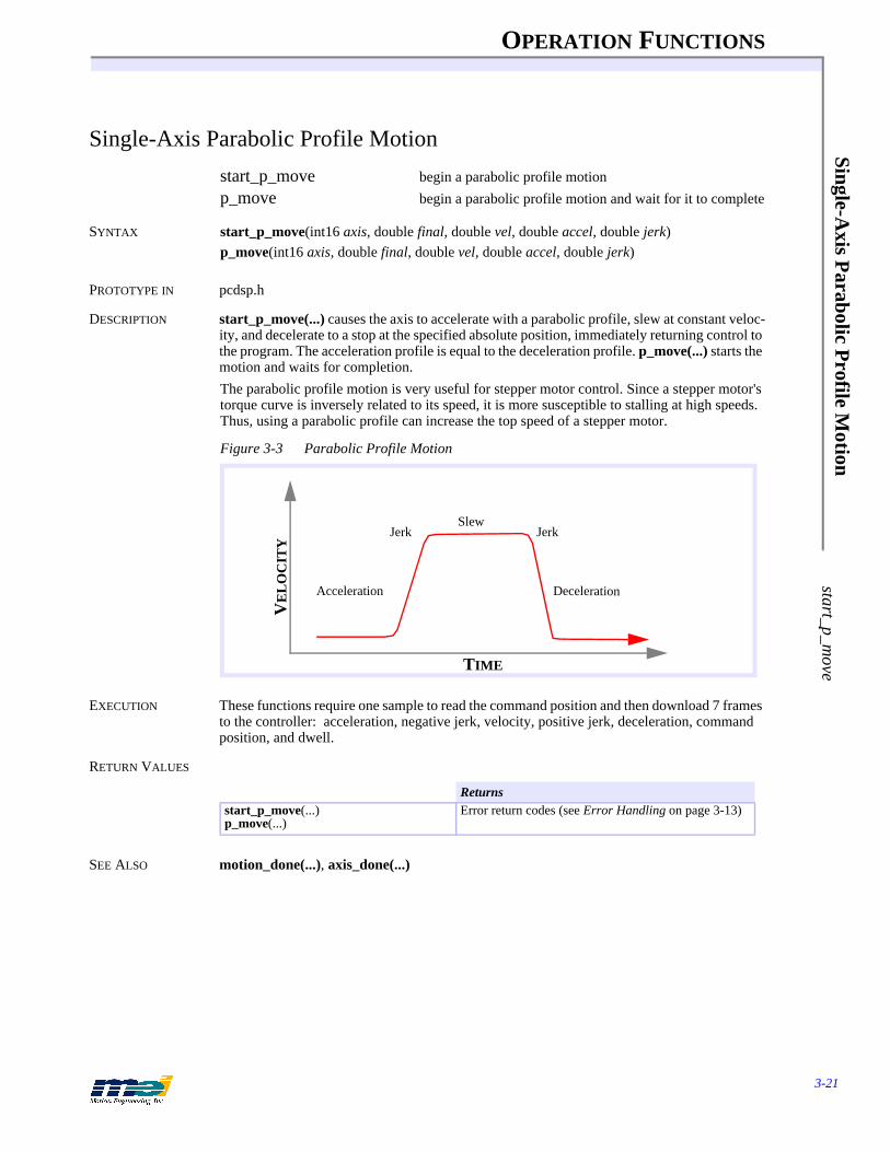
OPERATION FUNCTIONS
3-21
Single-Axis P
arabolic Profile M
otion start_p_m
ove
Single-Axis Parabolic Profile Motion
start_p_move begin a parabolic profile motionp_move begin a parabolic profile motion and wait for it to complete
SYNTAX start_p_move(int16 axis, double final, double vel, double accel, double jerk)p_move(int16 axis, double final, double vel, double accel, double jerk)
PROTOTYPE IN pcdsp.h
DESCRIPTION start_p_move(...) causes the axis to accelerate with a parabolic profile, slew at constant veloc-ity, and decelerate to a stop at the specified absolute position, immediately returning control to the program. The acceleration profile is equal to the deceleration profile. p_move(...) starts the motion and waits for completion.The parabolic profile motion is very useful for stepper motor control. Since a stepper motor's torque curve is inversely related to its speed, it is more susceptible to stalling at high speeds. Thus, using a parabolic profile can increase the top speed of a stepper motor.
Figure 3-3 Parabolic Profile Motion
EXECUTION These functions require one sample to read the command position and then download 7 frames to the controller: acceleration, negative jerk, velocity, positive jerk, deceleration, command position, and dwell.
RETURN VALUES
SEE ALSO motion_done(...), axis_done(...)
Returnsstart_p_move(...)p_move(...)
Error return codes (see Error Handling on page 3-13)
Slew
TIME
VE
LO
CIT
Y
DecelerationAcceleration
Jerk Jerk

OPERATION FUNCTIONS
3-22
Mul
ti-A
xis
Poi
nt-t
o-P
oint
Mot
ion
star
t_m
ove_
all
Multi-Axis Point-to-Point Motion
start_move_all begin a trapezoidal profile motion sequences on multiple axes
move_all begin the motion sequences and wait for completionwait_for_all wait for all of the motion sequences to complete
SYNTAX int16 start_move_all(int16 len, int16 * axes, double * position, double * velocity, double * accel)int16 move_all(int16 len, int16 * axes, double * position, double * velocity, double * accel)int16 wait_for_all(int16 len, int16 * axes)
PROTOTYPE IN pcdsp.h
DESCRIPTION start_move_all(...) causes the specified axes to accelerate, slew at constant velocity, and de-celerate to a stop at the specified absolute position. The move axes are specified by axes and the number of axes is defined by len. The function move_all(...) starts the motion and waits for completion. Both functions guarantee that motion begins on all axes at the same sample time.If the move distance is too short to reach the specified velocity the controller will accelerate for the first half of the distance and decelerate for the second half (triangular profile). wait_for_all(...) waits for the motion to complete for all of the specified axes.
EXECUTION These functions download 5 frames to each axis: acceleration, velocity, deceleration, com-mand position, and dwell.
RETURN VALUES
SEE ALSO motion_done(...), axis_done(...)
SAMPLE CODE This code moves axis 0 and axis 1 to positions 1000 and 2000 respectively. If we choose ve-locities and accelerations that are proportional to the ratio of the distances, then the axes will arrive at their endpoints at the same time (simultaneous motion).
# include <stdio.h># include "pcdsp.h"
int main(){
int16 axes [2] = {0, 1};double
positions[2] = {1000.0, 2000.0},velocities[2] = {4000.0, 8000.0},accels[2] = {50000.0, 100000.0};
if (dsp_init(PCDSP_BASE)) /* any problems initializing? */return dsp_error; /* just terminate the program. */
move_all(2, axes, positions, velocities, accels);
return dsp_error ; /* global variable provided by the library */}
Returnsstart_move_all(...)move_all(...)wait_for_all(...)
Error return codes (see Error Handling on page 3-13)
OPERATION FUNCTIONS
3-23
Velocity M
ove v_m
ove
Velocity Move
v_move accelerate to a constant velocity
SYNTAX int16 v_move(int16 axis, double velocity, double acceleration)
PROTOTYPE IN pcdsp.h
DESCRIPTION v_move(...) accelerates an axis to the specified constant velocity. The axis will continue to travel at a constant velocity until the velocity is changed or the axis is commanded to stop. The direction is determined by the sign of the velocity parameter.
RETURN VALUES
SEE ALSO set_velocity(...)
EXECUTION This function downloads 3 frames to the controller: acceleration, velocity, and dwell.
SAMPLE CODE This code moves axis 0 in velocity mode until a key is pressed.
# include "pcdsp.h"
int main(){
double position;
if (dsp_init(PCDSP_BASE)) /* any problems initializing? */return dsp_error; /* just terminate the program. */
v_move(0, 1000, 8000); /* accelerate axis 0 to 1000 counts/sec */
while (!kbhit()) /* wait for a key press */{ get_position(0, &position)
printf("Position: %8.0lf", position);}getch(); /* get the key */v_move(0, 0, 1000); /* decelerate axis 0 to a stop */
return dsp_error ; /* global variable provided by the library */}
NOTES The most common use for velocity control is homing sequences (see the sample programs on the Applications diskette). If you use this function in a loop make sure to wait for frames_left(...) to return FALSE before executing v_move(...) so that you do not fill the buffer.
Returnsv_move(...) Error return codes (see Error Handling on page 3-13)

OPERATION FUNCTIONS
3-24
Coo
rdin
ated
Axi
s M
apm
ap_a
xes
Coordinated Axis Map
map_axes configure the axis map for coordinated motion
SYNTAX int16 map_axes(int16 n_axes, int16 * map_array)
PROTOTYPE IN pcdsp.h
DESCRIPTION map_axes(...) initializes a group of axes for coordinated motion. map_axes(...) must be called before any coordinated motion function is used. The axes are specified by the map_array and the number of axes is defined by n_axes. For example if the x, y, and z coordinates correspond to axes 2, 4, and 5, the following code could be used to define the coordinate system:
int16 ax[3] = {2, 4, 5};map_axes(3, ax);
n_axes also configures the User I/O ports available to set_move_bit(...), reset_move_bit(...), and change_move_bit(...). For example, in the code above n_axes = 3, which sets user I/O ports 0,1, and 2 to be available during coordinated motion. Also, after map_axes(...) is called, be sure to initialize the ports as outputs or inputs.
EXECUTION This function configures the coordinated axes in software. It does not access the controller.
RETURN VALUES
SEE ALSO init_io(...), set_move_bit(...), reset_move_bit(...), change_move_bit(...)
SAMPLE CODE This code performs some circular coordinated moves. Axes 0 and 1 are used to produce an arc and then the axis map is changed. This is followed by an arc on axes 1 and 2.
# include <stdio.h># include "pcdsp.h"
int main(){
int16 axes[] = {0, 1, 2};
if (dsp_init(PCDSP_BASE)) /* any problems initializing? */return dsp_error; /* just terminate the program. */
map_axes(3, axes); /* map axes to be coordinated */ set_move_speed(800.0); /* initialize the vector speed */set_move_accel(2000.0); /* initialize the vector acceleration */
start_point_list();move_3(0.0, 0.0, 0.0); /* move axes to 0.0 */arc_2(100, 100, 180); /* move axes 0 and 1 in an arc */axes[0] = 2;axes[2] = 0;map_axes(3, axes); /* re-map the axes */set_move_speed(800.0); /*initialize the vector speed */set_move_accel(2000.0); /*initialize the vector acceleration */arc_2(100, 100, 180); /* move axes 2 and 1 in an arc */end_point_list();start_motion(); /* begin motion */
return dsp_error; /* global variable provided by the library */}
NOTES We recommend calling map_axes(...) at the beginning of your program, after dsp_init(...).Be sure to always call set_move_speed(…) and set_move_accel(…) after map_axes(…).
Returnsmap_axes(...) Error return codes (see Error Handling on page 3-13)

OPERATION FUNCTIONS
3-25
Start/End C
oordinated Point L
ist start_point_list
Start/End Coordinated Point List
start_point_list initialize a list of pointsend_point_list terminate a point list get_last_point read the last point that was added to the list
SYNTAX int16 start_point_list(void)int16 end_point_list(void)void get_last_point(double * x)
PROTOTYPE IN pcdsp.h
DESCRIPTION start_point_list(...) begins a list of points describing a continuous coordinated motion path. end_point_list(...) terminates the point list. The motion will stop at the last point entered in the path. start_point_list(…) automatically checks if a previous point list has been completed. If the previous point list has not been completed, then end_point_list(…) will be called automat-ically.After start_point_list(...), each subsequent call to a coordinated motion function creates and downloads point(s) to the frame buffer. The path between each point is interpolated by blend-ing accelerations. This produces a sequence of blended moves which approximates a path de-scribed by the straight lines joining the points.
The DSP controller begins executing the list of points when start_motion(...) is called. start_motion(...) can be called at any time after the first two points have been downloaded to the controller. If the coordinated path is larger than the DSP’s buffer then the host processor must keep adding points before the DSP needs them. If the DSP runs out of points then an E-Stop Event will be triggered on all of the mapped axes and an axis source of ID_OUT_OF_FRAMES will be returned.
Make sure when creating the point list to call start_motion(...) before completely filling the buffer. Once the buffer is full, no points will be downloaded until space becomes available.
get_last_point(...) reads the last point generated in the point list. It is very useful for finding the endpoint absolute coordinates of an arc.
RETURN VALUES
SEE ALSO map_axes(...), move_n(...), arc_2(...), add_point(...), add_arc(...), start_motion(...), stop_motion(...), fifo_space(...), frames_to_execute(...)
Returnsstart_point_list(...)end_point_list(...)get_last_point(...)
Error return codes (see Error Handling on page 3-13)
OPERATION FUNCTIONS
3-26
Coo
rdin
ated
Mot
ion
Par
amet
ers
set_
mov
e_sp
eed
Coordinated Motion Parameters
set_move_speed set vector velocityset_move_accel set vector accelerationset_arc_division set interpolation arc segment lengtharc_optimization enable/disable optimum acceleration calculations for arcsset_move_ratio set the mapped axes resolution ratios
SYNTAX int16 set_move_speed(double speed)int16 set_move_accel(double accel)int16 set_arc_division(double degrees)int16 arc_optimization(int16 opt)int16 set_move_ratio(double * ratio)
PROTOTYPE IN pcdsp.h
DESCRIPTION The vector velocity and vector acceleration can be specified for coordinated motion by set_move_speed(...) and set_move_accel(...). set_move_speed(...) and set_move_accel(...) can also be used inside a point list to change the vector acceleration and vector velocity at spe-cific points.set_arc_division(...) specifies the maximum angle (in degrees) between successive points along the arc. The default is 5 degrees.
arc_optimization(...) enables (opt = TRUE) or disables (opt = FALSE) the automatic calcula-tion of the optimum acceleration for an arc. The default state for arc optimization is enabled. When arc_optimization(...) is enabled, circular interpolation is greatly improved by choosing the best acceleration for the motion. The optimum acceleration is given by the following for-mulas:
Aopt = V²/d or Aopt = V²/rθ
where Aopt is the best acceleration, V is the set_move_speed(...) velocity, d is the segment length, r is the radius, and θ is the arc division (in radians).
If the acceleration is higher than Aopt, the linear portions may be noticeable. If the acceleration is lower than Aopt, the motion will be slowed during the arc and it will lose its roundness.
Both arc_2(...) and add_arc(...) automatically change the acceleration to Aopt during the cir-cular interpolated move. After the circular interpolated move is finished, the acceleration is set to the original set_move_accel(...) acceleration.
set_move_ratio(double * ratio) configures scale factors for coordinated axes, often required when the mechanical resolutions of the axes are different. The size of the ratio array and its elements are based on the axes mapped in map_axes(...). For example, to draw a circle in a 2-axis system with the y-axis having twice the resolution as the x-axis, first call map_axes(...), and then call set_move_ratio(ratio), where ratio[0] = 1.0 and ratio[1] = 2.0.

OPERATION FUNCTIONS
3-27
Coordinated M
otion Param
eters set_m
ove_speed
RETURN VALUES
SEE ALSO arc_2(...), add_arc(...)
SAMPLE CODE This code performs some linear coordinated moves. The vector velocity is increased at the sec-ond point.
# include "pcdsp.h"
int main(){
int16 axes[] = {0, 1, 2};
if (dsp_init(PCDSP_BASE)) /* any problems initializing? */return dsp_error; /* just terminate the program. */
map_axes(3, axes); /* map axes to be coordinated */ set_move_speed(800.0); /* initialize the vector speed */set_move_accel(4000.0); /* initialize the vector acceleration */
start_point_list();move_3(100.0, 0.0, 100.0); /* move axes to x, y, z*/set_move_speed(1200); /* new speed at next point */move_3(800.0, 100.0, 400.0);move_3(0.0, 0.0, 0.0);end_point_list();start_motion(); /* begin motion */
return dsp_error; /* global variable provided by the library */}
NOTES We strongly recommend that you DO NOT DISABLE arc_optimization(...).
Returnsset_move_speed(...)set_move_accel(...)set_arc_division(...)arc_optimization(...)set_move_ratio(...)
Error return codes (see Error Handling on page 3-13)
OPERATION FUNCTIONS
3-28
Star
t/St
op C
oord
inat
ed M
otio
nst
art_
mot
ion
Start/Stop Coordinated Motion
start_motion start the execution of a coordinated motion profilestop_motion stop the execution of a coordinated motion profileset_points set the number of points before motion is automatically
startedall_done reads if the coordinated motion is complete
SYNTAX int16 start_motion(void)int16 stop_motion(void)int16 set_points(int16 points)int16 all_done(void)
PROTOTYPE IN pcdsp.h
DESCRIPTION start_motion(...) starts motion along a pre-defined path. There must be at least 2 points in the points list before start_motion(...). Once start_motion(...) has been called the host processor must keep adding points to the list or call end_point_list(...). If a point is reached and no new point is defined, an E-Stop event will be triggered on all of the mapped axes.stop_motion(...) causes a Stop event to occur on all of the mapped axes, causing the motion to decelerate to a stop. The deceleration rate is determined by the set_stop_rate(...) function.set_points(...) specifies the number of points to be downloaded before motion starts. The func-tion library automatically calls start_motion(...) when the number of downloaded points ex-ceeds the points parameter.all_done(...) returns TRUE when all of the mapped axes have completed the coordinated mo-tion sequence.
RETURN VALUES
SAMPLE CODE This code performs some linear coordinated moves.# include "pcdsp.h"
int main(){
int16 axes[] = {0, 1, 2, 3};
if (dsp_init(PCDSP_BASE)) /* any problems initializing? */return dsp_error; /* just terminate the program. */
map_axes(3, axes); /* map axes to be coordinated */ set_move_speed(800.0); /* initialize the vector speed */set_move_accel(2000.0); /* initialize the vector acceleration */
start_point_list();move_3(100.0, 100.0, 0.0); /* move axes to x, y, z */move_3(200.0, 200.0, 200.0);end_point_list();
getch(); /* wait for a key */start_motion(); /* begin motion */
return dsp_error; /* global variable provided by the library */}
Returnsstart_motion(...)stop_motion(...)set_points(...)
Error return codes (see Error Handling on page 3-13)
all_done(...) Value
OPERATION FUNCTIONS
3-29
Linear C
oordinated Motion
move_2
Linear Coordinated Motion
move_2 add a 2-axis point to the pathmove_3 add a 3-axis point to the pathmove_4 add a 4-axis point to the pathmove_n add an arbitrary-number-of-axes point to the pathadd_point add a point to the list
SYNTAX int16 move_2(double x, double y)int16 move_3(double x, double y, double z)int16 move_4(double x, double y, double z, double w)int16 move_n(double * x)int16 add_point(double * x)
PROTOTYPE IN pcdsp.h
DESCRIPTION These functions add a point to the list of points defining the path. add_point(...) is provided for compatibility with earlier software releases. It is identical to move_n(...).Typically, each linear interpolated point requires 2 frames per axis.
These functions can also be called outside of a point list which results in immediate execution. When used outside of a point list successive linear coordinated moves are not blended together.
These functions check if there is enough room in the frame buffer before downloading frames. If there is not enough room then the function will return the error code DSP_NO_ROOM.
RETURN VALUES
SAMPLE CODE This code performs some individual linear coordinated moves.# include "pcdsp.h"
int main(){
int16 axes[] = {0, 1, 2};
if (dsp_init(PCDSP_BASE)) /* any problems initializing? */return dsp_error; /* just terminate the program. */
map_axes(3, axes); /* map axes to be coordinated */ set_move_speed(800.0);set_move_accel(2000.0);
move_3(100.0, 0.0, 0.0); /* move axes to x, y, z */move_2(1000.0, 1000.0); /* move to position x, y */
return dsp_error; /* global variable provided by the library */}
NOTES move_2(...), move_3(...), etc., are added for convenience and should be used with correspond-ing systems. For example if you have a 4-axis system but only want to move 2 axes then use move_2(...). map_axes(...) can be used to switch the system of axes.
Returnsmove_2(...)move_3(...)move_4(...)move_n(...)add_point(...)
Error return codes (see Error Handling on page 3-13)
OPERATION FUNCTIONS
3-30
Cir
cula
r C
oord
inat
ed M
otio
nar
c_2
Circular Coordinated Motion
arc_2 add a 2-axis circular arc to the point listadd_arc add a 2-axis circular arc to the point list
SYNTAX int16 arc_2(double x_center, double y_center, double angle)int16 add_arc(double * center, double angle, double division)
PROTOTYPE IN pcdsp.h
DESCRIPTION arc_2(...) creates a sequence of points following a circular arc and adds them to the point list. The arc starts at the last point in the point buffer and continues through the specified angle. A positive value for angle produces clockwise arcs and a negative value produces counter-clock-wise arcs. The center of the arc is specified by the parameters x_center and y_center. division specifies the maximum angle (in degrees) between successive points along the arc. add_arc(...) is identical to arc_2(...) except that the parameter center is a pointer to an array of doubles.Typically, each circular interpolated point (one point per division) requires 2 frames per axis.
These functions can also be called outside of a point list which results in immediate execution. When used outside of a point list successive circular coordinated moves are not blended togeth-er.
These functions check if there is enough room in the frame buffer before downloading frames. If there is not enough room then the function will return the error code DSP_NO_ROOM.
Circular interpolation is greatly improved by choosing the best acceleration for the motion. The optimum acceleration is given by the following formulas:
Aopt = V²/d or Aopt = V²/rθ
where Aopt is the best acceleration, V is the set_move_speed(...) velocity, d is the segment length, r is the radius, and θ is the arc division (in radians).
If the acceleration is higher than Aopt, the linear portions may be noticeable. If the acceleration is lower than Aopt, the motion will be slowed during the arc and it will lose its roundness.
Both arc_2(...) and add_arc(...) automatically change the acceleration to Aopt during the cir-cular interpolated move. After the circular interpolated move is finished, the acceleration is set to the original set_move_accel(...) acceleration. The automatic optimum acceleration calcula-tion can be disabled with arc_optimization(...).
SEE ALSO arc_optimization(...), set_arc_division(...), fifo_space(...), frames_left(...)
RETURN VALUES
NOTES When arc_optimization(...) is enabled, about 1/2 as many frames are used when arc_optimization(...) is disabled.
Returnsarc_2(...)add_arc(...)
Error return codes (see Error Handling on page 3-13)

OPERATION FUNCTIONS
3-31
User I/O
During C
oordinated Motion
set_move_bit
User I/O During Coordinated Motionset_move_bit turn on output bit at next pointreset_move_bit turn off output bit at next pointchange_move_bit change state of output bit at next pointset_move_output set output state (16-bit) at next point
SYNTAX int16 set_move_bit(int16 bitNo)int16 reset_move_bit(int16 bitNo)int16 change_move_bit(int16 bitNo, int16 state)int16 set_move_output(unsigned int16 value)
PROTOTYPE IN pcdsp.h
DESCRIPTION During coordinated motion, these functions change the state of the output bits at the beginning of the acceleration into the next point. The number of ports that can be accessed with the coor-dinated I/O functions is equal to the number of axes configured with map_axes(...).Use set_move_bit(...), reset_move_bit(...), and change_move_bit(...) to set or clear an indi-vidual output bit during coordinated motion. Use set_move_output(...) to set the first 16 bits of User I/O (ports 0, 1). Before using any of the User I/O functions, call init_io(...) to initialize the User I/O.
PINOUTS See the appropriate Install Guide.
SEE ALSO init_io(...), set_io(...)
RETURN VALUES
SAMPLE CODE This code performs some linear coordinated moves, toggling user I/O bits at each point.# include <stdio.h># include "pcdsp.h"
int main(){
int16 axes[] = {0, 1};
if (dsp_init(PCDSP_BASE)) /* any problems initializing? */return dsp_error; /* just terminate the program. */
init_io(0, IO_OUTPUT); /* initialize port 0 as outputs */set_io(0, 0); /* turn off all bits on port 0 */map_axes(2, axes); /* map axes to be coordinated */ set_move_speed(800.0);set_move_accel(2000.0);
start_point_list();set_move_bit(0); /* turn on bit 0 at next point */move_2(1000.0, 1000.0); /* move axes to x,y (bit 0 will turn on) */set_move_output(0); /* turn off bits on port 0 at next point */move_2(3000.0, 100.0); /* move axes to x,y */end_point_list();start_motion();
Returnsset_move_bit(...)reset_move_bit(...)change_move_bit(...)set_move_output(...)
Error return codes (see Error Handling on page 3-13)

OPERATION FUNCTIONS
3-32
Use
r I/
O D
urin
g C
oord
inat
ed M
otio
nse
t_m
ove_
bit
return dsp_error; /* global variable provided by the library */}
NOTES set_move_bit(...), reset_move_bit(...), change_move_bit(...), and set_move_output(...) are only valid when used between a start_point_list(...) and end_point_list(...). All of the stan-dard I/O functions: set/get_io(...), set/reset_bit(...), change_bit(...), and bit_on(...) can be used for immediate access to the user I/O.

OPERATION FUNCTIONS
3-33
Cubic Spline C
oordinated Motion
load_spline_motion
Cubic Spline Coordinated Motion
load_spline_motion download frames for an n-axis cubic spline coordinated mo-tion
start_spline_motion start the execution of a cubic spline coordinated motion
SYNTAX int16 load_spline_motion(int16 n_axes, int16 * axis_map, int16 n_points, long * (* point_list), double * g, int16 * end_flag)int16 start_spline_motion(int16 n_axes, int16 * axis_map)
PROTOTYPE IN pcdsp.h
DESCRIPTION load_spline_motion(...) calculates a coordinated cubic spline motion and downloads a se-quence of frames to the DSP’s frame buffer. The number of axes is specified by n_axes and the particular axes are specified by axis_map.The interpolated cubic spline is calculated based on the point_list which contains positions (in units of encoder counts) and times (in units of DSP samples). The number of points is specified by n_points. The jerk profiles between each point are based on the distances and times between the points. Each interpolated point requires one frame per axis. The DSP frame buffer can hold a maximum of 600 frames.
The g factor determines the degree of smoothness (curvature) of the interpolated cubic spline. The valid range for g is between 0.0 (straight line sections between points) and 1.0 (smoothest curve between points).
The cubic spline algorithm guarantees that the motion path will hit each point in the point_list exactly. The accuracy of the path between the points depends on the distance between the points and the g factor. Shorter distances and smaller values of g produce the most accurate paths.
The end_flag specifies the path at the start and end points. The motion at the end points can be configured for a non-zero velocity path (end_flag = FALSE) or zero velocity path (end_flag = TRUE).
A non-zero velocity path creates a profile that interpolates the motion beyond the end points. This creates the most direct profile to the end points. This works best with points lists that ac-count for acceleration and deceleration (points closer together) at the end points. A zero velocity path creates the smoothest (usually not direct) profile to the end points.
Figure 3-4 End Point Handling
start_spline_motion(...) executes the motion profile for n_axes specified by the axis_map.
TIME
PO
SIT
ION
Zero Velocity
Non-Zero Velocity

OPERATION FUNCTIONS
3-34
Cub
ic S
plin
e C
oord
inat
ed M
otio
nlo
ad_s
plin
e_m
otio
n
RETURN VALUES
LIMITATIONS Cubic Spline Coordinated motion functions not supported under Visual Basic.
SAMPLE CODE This code creates a simple cubic spline coordinated motion path for 2 axes. The command po-sitions are displayed during the motion execution.
# include <stdio.h># include <stdlib.h># include <conio.h># include <dos.h># include "pcdsp.h"
# define POINTS 10# define AXES 2
static long time_data[POINTS]; /* time units are in DSP samples */static long pos_data_0[POINTS];static long pos_data_1[POINTS];
void display(int16 n_axes, int16 * axis_map){
int16 i;double cmd, vel;
while (!kbhit()){ for (i = 0; i < n_axes; i++)
{ get_command(axis_map[i], &cmd);get_velocity(axis_map[i], &vel);printf("Ax:%1d C:%6.0lf V:%6.0lf ", axis_map[i], cmd, vel);
}printf("\n");
}getch();
}
int main(){
int16 i, sample_rate, end_flag[AXES], axis_map[AXES] = {0, 1};double g [AXES];long * point[AXES+1];
if (dsp_init(PCDSP_BASE)) /* any problems initializing? */return dsp_error; /* just terminate the program. */
for(i = 1; i < POINTS; i++) /* create a simple point list */{ time_data[i] = time_data[i-1] + dsp_sample_rate();
pos_data_0[i] = pos_data_0[i-1] + 2000;pos_data_1[i] = pos_data_1[i-1] + 1500;
}point[0] = time_data;point[1] = pos_data_0;point[2] = pos_data_1;g[0] = 1.0;g[1] = 1.0;end_flag[0] = TRUE; /* zero velocity path end points */end_flag[1] = TRUE;
load_spline_motion(AXES, axis_map, POINTS, point, g, end_flag);printf("Frames loaded. Fifo space: %d\n\n", fifo_space());start_spline_motion(AXES, axis_map);display(AXES, axis_map);
Returnsload_spline_motion(...)start_spline_motion(...)
Error return codes (see Error Handling on page 3-13)

OPERATION FUNCTIONS
3-35
Cubic Spline C
oordinated Motion
load_spline_motion
return dsp_error; /* global variable provided by the library */}
OPERATION FUNCTIONS
3-36
Fra
me
Buf
fer
Man
agem
ent
fifo_
spac
e
Frame Buffer Management
fifo_space returns the number of available frames in the DSP’s bufferframes_to_execute returns the number of frames left to execute for an axis
SYNTAX int fifo_space(void)int frames_to_execute(int axis)
PROTOTYPE IN pcdsp.h
DESCRIPTION The DSP has frame counters to keep track of the used and free frames. fifo_space(void) returns the number of available frames left in the buffer. frames_to_execute(...) returns the number of frames left to execute for an axis. The frame buffer has a fixed size of 600 frames.At boot time or after a dsp_reset(...), fifo_space(...) will return 600. After frames are down-loaded, the number of free frames will be reduced. The last frame for each axis will not be re-leased to the free list, it acts as a place holder. Therefore, fifo_space(...) may return less than 600 (one less per axis).
SEE ALSO start_point_list(...), end_point_list, move_2(...), arc_2(...)
RETURN VALUES
SAMPLE CODE This code demonstrates how to manage the DSP frame buffer for continuous contouring. This sample is programmed as a state machine.
# include <stdio.h># include <conio.h># include <stdlib.h># include "pcdsp.h"
int state; /* one state variable for axes 0 and 1 */int seq_flag; /* flag to enable/disable sequence repeat */
# define READY 0 /* State Values */# define BEGIN_SEQUENCE 1# define REPEAT_SEQUENCE 2# define END_SEQUENCE 3
# define SPACE 300 /* free frames before next sequence */
void initialize(void){
int16 map[2] = {0, 1};if (dsp_init(PCDSP_BASE))/* any problems initializing? */
exit(1); /* just terminate the program. */map_axes(2, map); /* setup coordinated axes */seq_flag = 0; /* initialize sequence repeat flag */set_move_speed(4000.0);set_move_accel(80000.0);
}
void sequence(void){
move_2(100.0, 200.0);arc_2(200.0, 200.0, -360);arc_2(300.0, 300.0, 180);move_2(0.0, 0.0);
Returnsfifo_space(...)frames_to_execute(...)
Values
OPERATION FUNCTIONS
3-37
Fram
e Buffer M
anagement
fifo_space
}
void CheckState(void){
switch (state){ case BEGIN_SEQUENCE:
start_point_list();sequence();start_motion();seq_flag = TRUE;state = READY;break;
case REPEAT_SEQUENCE:sequence();state = READY;break;
case END_SEQUENCE:end_point_list();seq_flag = FALSE;state = READY;break;
case READY:break;
}}
int main(){
int16 axis, done, key;
initialize();printf("\nb=begin, e=end, esc=quit\n");for (done = 0; !done; ){ CheckState();
if ((fifo_space() > SPACE) && seq_flag)state = REPEAT_SEQUENCE;
if (kbhit()) /* key pressed? */{ key = getch();
switch (key){ case 'b':
state = BEGIN_SEQUENCE;break;
case 'e':state = END_SEQUENCE;break;
case 0x1B: /* <ESC> */done = TRUE;break;
}}
}return 0;
}

OPERATION FUNCTIONS
3-38
Pos
itio
n C
ontr
olse
t_po
sitio
n
Position Control
set_position set the actual position and command positionget_position get the current actual positiondsp_encoder read the 16-bit value directly from the encoder circuitryset_command set the current command position registerget_command get the current command positionset_last_command sets the last command position valueget_last_command get the last command positionget_error get the current position error
SYNTAX int16 set_position(int16 axis, double position)int16 get_position(int16 axis, double * position)int16 dsp_encoder(int16 axis)int16 set_command(int16 axis, double position)int16 get_command(int16 axis, double * position)
int16 set_last_command(int16 axis, double position)int16 get_last_command(int16 axis, double * position)int16 get_error(int16 axis, double * error)
PROTOTYPE IN pcdsp.h
DESCRIPTION set_position(...) updates the command and actual position registers. set_position(...) loads a frame into the DSP’s frame buffer which sets the axis’ command and actual position in the same sample period. get_position(...) reads the axis’ actual position. The command position resolu-tion is 32 bits whole and 32 bits fractional. The actual position resolution is 32 bits whole. Both the command and actual positions are updated by the DSP every sample.dsp_encoder(...) reads the 16-bit actual position directly from the encoder circuitry which is mapped in the external memory of the DSP.
set_command(...) updates an axis’ command position register. Be careful, changes in the com-mand position will cause the motor to jump immediately to the new position. get_command(...) reads an axis’ command position.
set_last_command(…) sets the last command position variable. get_last_command(...) reads a library internal global variable. The last command position is used in the calculation of abso-lute position moves. These functions are very helpful when mixing function calls that generate point-to-point and coordinated and user-defined frame motion profiles.
get_error(...) returns the difference between an axis’ command and actual positions. The po-sition error resolution is 16 bits whole. The position error does not rollover, it saturates at +/-32,767 counts.
SERCOS set_position(…) will work properly with drives configured for Velocity or Torque mode. If a SERCOS drive is configured for Position mode, set_position(…) will return DSP_FUNCTION_NOT_APPLICABLE unless the drive is executing the drive controlled homing procedure (IDN 148).

OPERATION FUNCTIONS
3-39
Position C
ontrol set_position
RETURN VALUES
EXECUTION set_position(...) downloads a frame to update the command and actual positions. dsp_encoder(...) performs a 16-bit read directly from the encoder chip. The other functions perform reads/writes to the DSP’s external data memory. get_last_command(...) reads the last command software global variable.
SAMPLE CODE This function resets the command and actual position register for axis 0, and displays its posi-tion through a move to 100,000 counts. Then it displays the axis’ 32 bit actual position (from the DSP) and the 16 bit encoder value (from the encoder circuitry).
# include <stdio.h># include "pcdsp.h"
int main(){
double actual;
if (dsp_init(PCDSP_BASE)) /* any problems initializing? */return dsp_error ; /* just terminate the program. */
set_position(0, 0.); /* reset command and actual positions */while (!motion_done(0)) /* wait for position reset completion */
;start_move(0, 100000.0, 5000., 10000.); /* move to 100,000. */
while (!motion_done(0)){ get_position(0, &actual); /* 32bit actual position */
printf("Current Position: %12.0lf\r", actual);}printf("\nEnc: %d\n", dsp_encoder(0)); /* 16bit encoder counter */
return dsp_error ; /* global variable provided by the library */}
NOTES Often we have seen customer code that calls a set_position(...) followed by a get_position(...). Since set_position(...) creates a frame that is buffered by the DSP, it is possible for the CPU to read the actual position register before the set_position(...) is executed.The value read from dsp_encoder(...) may not be equal to the actual position. The encoder cir-cuitry is reset at power-up or when dsp_reset(...) is called.
Returnsset_position(...)get_position(...)dsp_encoder(...)set_command(...)get_command(...)set_last_command(...)get_last_command(...)get_error(...)
Error return codes (see Error Handling on page 3-13)
If a drive is configured for Position mode, calling set_position(...) at inappropriate times will cause the motor to jump.
Under normal operating conditions, setting the position is not advised. Note, however that some functions (like drive homing procedures) will call set_position(...), and in those cases, it’s OK.
WARNING!

OPERATION FUNCTIONS
3-40
Tra
ject
ory
Con
trol
set_
velo
city
Trajectory Control
set_velocity set the command velocityget_velocity get the command velocityset_accel set the command accelerationget_accel get the command accelerationset_jerk set the command jerkget_jerk get the command jerk
SYNTAX int16 set_velocity(int16 axis, double velocity)int16 get_velocity(int16 axis, double * velocity)int16 set_accel(int16 axis, double acceleration)int16 get_accel(int16 axis, double * acceleration)int16 set_jerk(int16 axis, double jerk)int16 get_jerk(int16 axis, double * jerk)
PROTOTYPE IN pcdsp.h
DESCRIPTION set_velocity(...) updates an axis’ command velocity register. The direction is determined by the sign of the velocity. get_velocity(...) reads the axis’ current command velocity.set_accel(...) updates an axis’ command acceleration register. The direction is determined by the sign of the acceleration. get_accel(...) reads the axis’ current command acceleration.
set_jerk(...) updates an axis’ command jerk register. The direction is determined by the sign of the jerk. get_jerk(...) reads the axis’ current command jerk.
The command velocity, acceleration, and jerk all have a resolution of 16 bits whole and 32 bits fractional. Every sample the DSP updates the trajectory:
Tn = Tn-1 + FdSpd Tn is the time at sample nAn = An-1 + FdSpd * J J is the jerkVn = Vn-1 + FdSpd * An An is the acceleration at sample nXn = Xn-1 + FdSpd * Vn Vn is the velocity at sample n
Xn is the command position at sample nFdSpd is the feed speed
RETURN VALUES
Returnsset_velocity(...)get_velocity(...)set_accel(...)get_accel(...)set_jerk(...)get_jerk(...)
Error return codes (see Error Handling on page 3-13)

OPERATION FUNCTIONS
3-41
Trajectory C
ontrol set_velocity
SAMPLE CODE This code instantaneously sets the command velocity on axis 0 to 1000 counts/sec. The axis remains in motion at constant velocity until a key is pressed.
# include "pcdsp.h"
int main(){
if (dsp_init(PCDSP_BASE)) /* any problems initializing? */return dsp_error; /* just terminate the program. */
set_velocity(0, 1000); /* travel indefinitely at 1000 counts/sec */getch(); /* wait for a key press */set_velocity(0, 0.0); /* stop axis 0 */
return dsp_error ; /* global variable provided by the library */}
NOTES set_accel(...) and set_jerk(...) are rarely used. A non-zero set_accel(...) or set_jerk(...) will cause an axis to increase in velocity until the command jerk or acceleration is set to zero. These functions can cause an axis to continuously accelerate if not used properly.
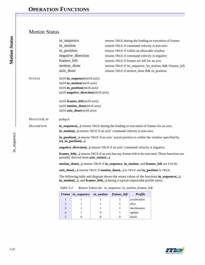
OPERATION FUNCTIONS
3-42
Mot
ion
Stat
usin
_seq
uenc
e
Motion Status
in_sequence returns TRUE during the loading or execution of framesin_motion returns TRUE if command velocity is non-zeroin_position returns TRUE if within an allowable windownegative_direction returns TRUE if command velocity is negativeframes_left returns TRUE if frames are left for an axismotion_done returns TRUE if !in_sequence, !in_motion, && !frames_leftaxis_done returns TRUE if motion_done && in_position
SYNTAX int16 in_sequence(int16 axis)int16 in_motion(int16 axis)int16 in_position(int16 axis)int16 negative_direction(int16 axis)
int16 frames_left(int16 axis)int16 motion_done(int16 axis)int16 axis_done(int16 axis)
PROTOTYPE IN pcdsp.h
DESCRIPTION in_sequence(...) returns TRUE during the loading or execution of frames for an axis.in_motion(...) returns TRUE if an axis’ command velocity is non-zero.
in_position(...) returns TRUE if an axis’ actual position is within the window specified by set_in_position(...).
negative_direction(...) returns TRUE if an axis’ command velocity is negative.
frames_left(...) returns TRUE if an axis has any frames left to be executed. These functions are partially derived from axis_status(...).
motion_done(...) returns TRUE if in_sequence, in_motion, and frames_left are FALSE.
axis_done(...) returns TRUE if motion_done(...) is TRUE and in_position is TRUE.
The following table and diagram shows the return values of the functions in_sequence(...), in_motion(...), and frames_left(...) during a typical trapezoidal profile move.
Table 3-2 Return Values for in_sequence, in_motion, frames_left
Frame in_sequence in_motion frames_left Profile
1 1 1 1 acceleration2 1 1 1 slew3 1 1 1 deceleration4 1 0 1 update5 0 0 0 dwell
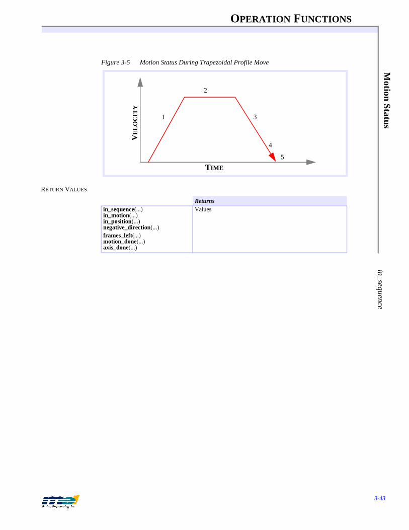
OPERATION FUNCTIONS
3-43
Motion Status
in_sequence
Figure 3-5 Motion Status During Trapezoidal Profile Move
RETURN VALUES
Returnsin_sequence(...)in_motion(...)in_position(...)negative_direction(...)frames_left(...)motion_done(...)axis_done(...)
Values
2
TIME
VE
LO
CIT
Y
1 3
4
5

OPERATION FUNCTIONS
3-44
Axi
s St
atus
axis
_sta
tus
Axis Status
axis_status returns the current running condition of an axis
SYNTAX int16 axis_status(int16 axis)
PROTOTYPE IN pcdsp.h
DESCRIPTION axis_status(...)returns an integer value whose bits correspond to an axis’ current condition.
RETURN VALUE
SEE ALSO in_sequence(...), in_motion(...), in_position(...), negative_direction(...), frames_left(...)
SAMPLE CODE This code commands a trapezoidal profile move to an absolute location. After the move is com-plete, the status of the IN_POSITION bit is displayed.
# include <stdio.h># include <conio.h># include "pcdsp.h"
int main(){
if (dsp_init(PCDSP_BASE)) /* any problems initializing? */return dsp_error; /* just terminate the program. */
start_move(0, 1000, 2000, 8000);while (!motion_done(0)) /* wait for the command profile completion */
;
while (!kbhit())printf("In Position %d\r", axis_status(0) & IN_POSITION);
getch();
return dsp_error ; /* global variable provided by the library */}
NOTES The motion status functions in_sequence(...), in_motion(...), in_position(...), negative_direction(...), and frames_left(...) are partially derived from axis_status(...). The functions may return different values than the status word. We strongly recommend using the individual functions.
Table 3-3 axis__status Conditions for an Axis
#define Value(hex) Description
IN_SEQUENCE 0x10 frames left in list for an axisIN_POSITION 0x20 within allowable position windowIN_MOTION 0x40 command velocity is non-zeroDIRECTION 0x80 sign of command velocityFRAMES_LEFT 0x100 frames to be executed for an axis
Returnsaxis_status(...) Value (integer that represents the status)

OPERATION FUNCTIONS
3-45
Axis State
axis_state
Axis State
axis_state returns the current running event on an axis
SYNTAX int16 axis_state(int16 axis)
PROTOTYPE IN pcdsp.h
DESCRIPTION axis_state(...) returns an integer value that corresponds to an axis’ current event. If the value is less than or equal to 2 then the state is normal. If the value is greater than 2 then an exception event has occurred.
RETURN VALUE
SAMPLE CODE This sample code moves axis 0 (velocity control), executes an STOP_EVENT, and waits for the motion to complete. Then the code reads the state of the axis 0.
# include <stdio.h># include <dos.h># include "pcdsp.h"
int main(){
if (dsp_init(PCDSP_BASE)) /* any problems initializing? */return dsp_error; /* just terminate the program. */
v_move(0, 1000, 8000); /* accelerate to constant velocity */delay(1000);set_stop(0); /* trigger a STOP_EVENT */while(! motion_done(0)) /* wait for event completion */
;if (axis_state(0) == STOP_EVENT)/* STOP_EVENT? */{ printf("\nA STOP_EVENT occurred on axis 0");
clear_status(0); /* clear the STOP_EVENT */}
return dsp_error ; /* global variable provided by the library */}
NOTES We recommend using axis_state(...) to check if an axis is working properly. If axis_state(...) returns an value greater than 2 then call axis_source(...) to find the cause of the event.
Table 3-4 axis_state Conditions for an Axis
#define Value Description
NO_EVENT 0 Ignore a conditionNEW_FRAME 2 Begin execution of the next sequenced frameSTOP_EVENT 8 Decelerate to a stop (at specified stop rate)E_STOP_EVENT 10 Decelerate to a stop (at specified E-stop rate)ABORT_EVENT 14 Disable PID control and the amplifier for this axis
Returnsaxis_state(...) Value (integer that represents the axis’ current event)

OPERATION FUNCTIONS
3-46
Axi
s So
urce
axis
_sou
rce
Axis Source
axis_source returns the cause of an exception event
SYNTAX int16 axis_source(int16 axis)
PROTOTYPE IN pcdsp.h
DESCRIPTION axis_source(...) returns an integer value that corresponds to the cause of an exception event on an axis. The integer return value describes the source of the event:
RETURN VALUE
SAMPLE CODE This code moves axis 0 using a call to v_move(...), executes an E_STOP_EVENT, and waits for the motion to complete. Then it reads the source of the event (generated from the host proces-sor) on axis 0.
# include <stdio.h># include <dos.h># include "pcdsp.h"
int main(){
if (dsp_init(PCDSP_BASE)) /* any problems initializing? */return dsp_error; /* just terminate the program. */
v_move(0, 1000, 8000); /* accelerate to constant velocity */delay(1000);set_e_stop(0); /* trigger an E_STOP_EVENT */while(! motion_done(0)) /* wait for event completion */
;/* did the host trigger an event? */if (axis_source(0) == ID_PC_COMMAND){ printf("\nThe host triggered the Event");
clear_status(0); /* clear the E_STOP_EVENT */}
return dsp_error ; /* global variable provided by the library */
Table 3-5 Possible Sources of Exception Events (Returned by axis_source)
#define Value Description
ID_NONE 0 No event has occurredID_HOME_SWITCH 1 Home logic was activatedID_POS_LIMIT 2 Positive limit input was activatedID_NEG_LIMIT 3 Negative limit input was activatedID_AMP_FAULT 4 Amplifier fault input was activatedID_X_NEG_LIMIT 7 Software negative travel limit exceededID_X_POS_LIMIT 8 Software positive travel limit exceededID_ERROR_LIMIT 9 Software position error exceededID_PC_COMMAND 10 CPU generated a stop, e-stop, abort, clear statusID_OUT_OF_FRAMES 11 Attempted next frame with no frame presentID_FEEDBACK_FAULT 12 Feedback fault detectedID_FEEDBACK_ILLEGAL_STATE 13 Improper feedback logic state detectedID_AXIS_COMMAND 14 Event triggered by another axis
Returnsaxis_source(...) Value (integer that corresponds to the cause of an exception event)

OPERATION FUNCTIONS
3-47
Axis Source
axis_source
}
NOTES Use axis_state(...) to read an axis’ current event. If axis_state(...) returns an value greater than 2, then call axis_source(...) to find the cause of the event.

OPERATION FUNCTIONS
3-48
Stop
Eve
ntse
t_st
op
Stop Event
set_stop generate a Stop Event on an axisset_stop_rate set the Stop Event deceleration rateset_boot_stop_rate set the boot Stop Event deceleration rateget_stop_rate read the Stop Event deceleration rateget_boot_stop_rate read the boot Stop Event deceleration rate
SYNTAX int16 set_stop(int16 axis)int16 set_stop_rate(int16 axis, double rate)int16 set_boot_stop_rate(int16 axis, double rate)int16 get_stop_rate(int16 axis, double * rate)int16 get_boot_stop_rate(int16 axis, double * rate)
PROTOTYPE IN pcdsp.h
DESCRIPTION set_stop(...) generates a Stop Event on an axis. A Stop Event causes the DSP to:1) prevent the Host from downloading frames2) set the axis_state(…) to STOP_EVENT3) set the axis_source(…) to ID_PC_COMMAND4) decelerate the axis to a stop5) clear the frames from the buffer for the axis
set_stop_rate(...) configures the Stop Event deceleration rate. clear_status(...) clears the Stop Event from the DSP's memory. get_stop_rate(...) reads the configured Stop Event deceleration rate from the DSP.
The boot functions store/read the Stop deceleration rates in boot memory. These are loaded on power-up or dsp_reset(...). Be sure to call mei_checksum(...) after the boot memory is modi-fied.
SEE ALSO clear_status(...), axis_state(...), axis_source(...), Event Recovery page 3-54
RETURN VALUES
SAMPLE CODE This code sets the Stop deceleration rate for axis 0. It then moves axis 0 (velocity control), ex-ecutes a Stop Event, waits for the event to complete, and then clears the event.
# include <stdio.h># include "pcdsp.h"
int main(){
if (dsp_init(PCDSP_BASE)) /* any problems initializing? */return dsp_error; /* just terminate the program. */
set_stop_rate(0, 10000); /* deceleration rate = 10000 cts/sec */v_move(0, 1000, 8000); /* accelerate to constant velocity */getch(); /* wait for a key */
Returnsset_stop(...)set_stop_rate(...)set_boot_stop_rate(...)get_stop_rate(...)get_boot_stop_rate(...)
Error return codes (see Error Handling on page 3-13)
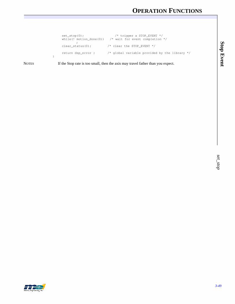
OPERATION FUNCTIONS
3-49
Stop Event
set_stop
set_stop(0); /* trigger a STOP_EVENT */while(! motion_done(0)) /* wait for event completion */
;clear_status(0); /* clear the STOP_EVENT */
return dsp_error ; /* global variable provided by the library */}
NOTES If the Stop rate is too small, then the axis may travel father than you expect.

OPERATION FUNCTIONS
3-50
Em
erge
ncy
Stop
Eve
ntse
t_e_
stop
Emergency Stop Event
set_e_stop generate an Emergency Stop Event on an axisset_e_stop_rate set the Emergency Stop Event deceleration rateset_boot_e_stop_rate set the boot Emergency Stop Event deceleration rateget_e_stop_rate read the Emergency Stop Event deceleration rateget_boot_e_stop_rate read the boot Emergency Stop Event deceleration rate
SYNTAX int16 set_e_stop(int16 axis)int16 set_e_stop_rate(int16 axis, double rate)int16 set_boot_e_stop_rate(int16 axis, double rate)int16 get_e_stop_rate(int16 axis, double * rate)int16 get_boot_e_stop_rate(int16 axis, double * rate)
PROTOTYPE IN pcdsp.h
DESCRIPTION set_e_stop(...) generates an E-Stop event on an axis. An E-Stop event causes the DSP to:1) prevent the Host from downloading frames2) set the axis_state(...) to E_STOP_EVENT3) set the axis_source(...) to ID_PC_COMMAND 4) decelerate the axis to a stop5) clear the frames from the buffer for the axis
Use set_e_stop_rate(...) to configure the E-Stop event deceleration rate. Use clear_status(...) to clear the E-Stop event from the DSP's memory. Use get_e_stop_rate(...) to read the configured E-Stop event deceleration rate from the DSP. The boot functions store/read the E-Stop deceleration rates in boot memory, which are loaded on power-up or dsp_reset(...). Be sure to call mei_checksum(...) after the boot memory is modified.
SEE ALSO clear_status(...), axis_state(...), axis_source(...), Event Recovery page 3-54
RETURN VALUES
SAMPLE CODE This code sets the E-Stop deceleration rate for axis 0. It then moves axis 0 (velocity control), executes an E-Stop event, waits for the event to complete, and then clears the event.
# include <stdio.h># include “pcdsp.h”int main(){
if (dsp_init(PCDSP_BASE)) /* any problems initializing? */return dsp_error; /* just terminate the program. */
set_e_stop_rate(0, 10000); /* deceleration rate = 10000 cts/sec */v_move(0, 1000, 8000); /* accelerate to constant velocity */getch(); /* wait for a key */set_e_stop(0); /* trigger an E_STOP_EVENT */while(! motion_done(0)) /* wait for event completion */
; clear_status(0); /* clear the E_STOP_EVENT */
Returnsset_e_stop(...)set_e_stop_rate(...)set_boot_e_stop_rate(...)get_e_stop_rate(...)get_boot_e_stop_rate(...)
Error return codes (see Error Handling on page 3-13)

OPERATION FUNCTIONS
3-51
Em
ergency Stop Event
set_e_stop
return dsp_error ; /* global variable provided by the library */}
NOTES If the E-Stop rate is too small, the axis may travel farther than you expect. This is critical for limit inputs configured for E-Stop events. If the E-Stop rate is too small and the motor hits the limit switch at a high velocity, the motor might not stop before the end of travel. The E-Stop event has a higher priority than the Stop event.

OPERATION FUNCTIONS
3-52
Abo
rt E
vent
cont
rolle
r_id
le
Abort Event
controller_idle set the controller into idle mode by generating an Abort event
disable_amplifier set the state of the amp enable output to the disabled state
SYNTAX int16 controller_idle(int16 axis)int16 disable_amplifier(int16 axis)
PROTOTYPE IN pcdsp.h
DESCRIPTION controller_idle(...) generates an Abort event on an axis. An Abort event causes the DSP to:1) set the axis_state(...) to ABORT_EVENT2) set the axis_source(...) to ID_PC_COMMAND 3) disable the axis’ PID control4) set the analog output voltage to the filter DF_OFFSET parameter5) disable the axis’ amp enable output6) clear the frames from the buffer for the axis7) prevent the Host from downloading frames
Notice that the DSP automatically disables the amp enable output during an Abort event. The DSP does NOT automatically re-enable the amplifier when an Abort event is cleared.
disable_amplifier(...) sets an axis’ amp enable output to the disabled state. The polarity of the amp enable output logic must be configured with set_amp_enable_level(...) before disable_amplifier(...) is used.
controller_run(...) clears the Abort event from the DSP's memory. The Abort Event has the highest priority in the DSP.
SEE ALSO controller_run(...), enable_amplifier(...), set_amp_enable(...), set_amp_enable_level(...), set_filter(...), set_dac_output(...), Event Recovery page 3-54
RETURN VALUES
SAMPLE CODE The following program executes an Abort Event, waits for the event to complete, clears the event, and re-enables the amplifier:
# include <stdio.h># include "pcdsp.h"
int main(){
if (dsp_init(PCDSP_BASE)) /* any problems initializing? */return dsp_error; /* just terminate the program. */
set_amp_enable_level(0, TRUE); /* active high amp enable logic */controller_idle(0); /* trigger an ABORT_EVENT */while(! motion_done(0)) /* wait for event completion */
;controller_run(0); /* clear the event and re-enable PID control */enable_amplifier(0); /* re-enable the amplifier */
return dsp_error ; /* global variable provided by the library */}
Returnscontroller_idle(...)disable_amplifier(...)
Error return codes (see Error Handling on page 3-13)

OPERATION FUNCTIONS
3-53
Abort E
vent controller_idle
NOTES To control the analog output directly, call controller_idle(...) or set_filter(...) with the PID val-ues equal to zero, and then adjust the DAC offset with set_filter(...) or set_dac_output(...).

OPERATION FUNCTIONS
3-54
Eve
nt R
ecov
ery
clea
r_st
atus
Event Recovery
clear_status clear a Stop Event or an E-Stop Event on an axiscontroller_run clear an Abort Event on an axisenable_amplifier set the state of the amp enable output to the enabled state
SYNTAX int16 clear_status(int16 axis)int16 controller_run(int16 axis)int16 enable_amplifier(int16 axis)
PROTOTYPE IN pcdsp.h
DESCRIPTION clear_status(...) clears the Stop Event or E-Stop Event on an axis:1) set the axis_state(...) to NO_EVENT2) set the axis_source(...) to ID_PC_COMMAND
The status of an axis cannot be cleared during the execution of an exception event. For exam-ple, after a Stop Event is generated you must wait until the axis has completed the event (wait for motion_done(...) to return TRUE) before calling clear_status(...). If the event has not com-pleted clear_status(...) won't do anything and will return error code 17.
controller_run(...) clears an Abort Event on an axis:
1) set the command position equal to the actual position2) reset the integrator3) enable the axis’ PID control4) set the axis_state(...) to NO_EVENT5) set the axis_source(...) to ID_PC_COMMAND
The status of an axis cannot be cleared during the DSP’s execution of an exception event. For example, after an Abort Event is generated you must wait until the axis has completed the event (wait for motion_done(...) to return TRUE) before calling controller_run(...). If the event has not completed controller_run(...) won't do anything and will return error code 17.
Notice that the DSP does not automatically re-enable the amp enable output during a controller_run(...). Once the Abort Event has been cleared, the amp enable output can be en-abled with enable_amplifer(...). The polarity of the amp enable output logic must be config-ured with set_amp_enable_level(...) before enable_amplifier(...) is used.
SERCOS enable_amplifier(…) enables a SERCOS drive if the communication loop is in phase 4. disable_amplifier(…) disables a SERCOS drive.
SEE ALSO controller_idle(...), disable_amplifier(...), set_amp_enable(...), set_amp_enable_level(...), set_filter(...)
RETURN VALUES
Returnsclear_status(...)controller_run(...)enable_amplifier(...)
Error return codes (see Error Handling on page 3-13)
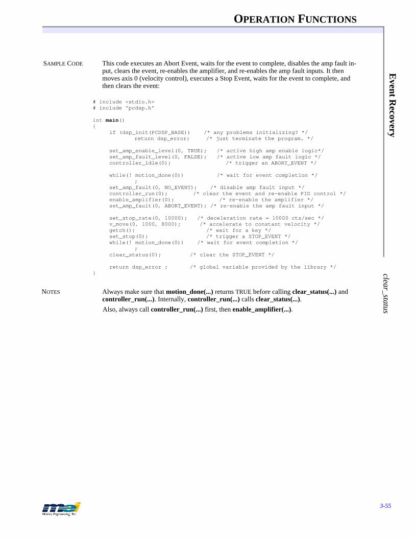
OPERATION FUNCTIONS
3-55
Event R
ecovery clear_status
SAMPLE CODE This code executes an Abort Event, waits for the event to complete, disables the amp fault in-put, clears the event, re-enables the amplifier, and re-enables the amp fault inputs. It then moves axis 0 (velocity control), executes a Stop Event, waits for the event to complete, and then clears the event:
# include <stdio.h># include "pcdsp.h"
int main(){
if (dsp_init(PCDSP_BASE)) /* any problems initializing? */return dsp_error; /* just terminate the program. */
set_amp_enable_level(0, TRUE); /* active high amp enable logic*/set_amp_fault_level(0, FALSE); /* active low amp fault logic */controller_idle(0); /* trigger an ABORT_EVENT */
while(! motion_done(0)) /* wait for event completion */;
set_amp_fault(0, NO_EVENT); /* disable amp fault input */controller_run(0); /* clear the event and re-enable PID control */enable_amplifier(0); /* re-enable the amplifier */set_amp_fault(0, ABORT_EVENT); /* re-enable the amp fault input */
set_stop_rate(0, 10000); /* deceleration rate = 10000 cts/sec */v_move(0, 1000, 8000); /* accelerate to constant velocity */getch(); /* wait for a key */set_stop(0); /* trigger a STOP_EVENT */while(! motion_done(0)) /* wait for event completion */
;clear_status(0); /* clear the STOP_EVENT */
return dsp_error ; /* global variable provided by the library */}
NOTES Always make sure that motion_done(...) returns TRUE before calling clear_status(...) and controller_run(...). Internally, controller_run(...) calls clear_status(...).Also, always call controller_run(...) first, then enable_amplifier(...).

OPERATION FUNCTIONS
3-56
Ded
icat
ed I
nput
sho
me_
switc
h
Dedicated Inputs
home_switch returns the state of the home logicpos_switch returns the state of the positive limit inputneg_switch returns the state of the negative limit inputamp_fault_switch returns the state of the amplifier fault input
SYNTAX int16 home_switch(int16 axis)int16 pos_switch(int16 axis)int16 neg_switch(int16 axis)int16 amp_fault_switch(int16 axis)
PROTOTYPE IN pcdsp.h
DESCRIPTION home_switch(...) returns the current state of an axis’ home logic. The home logic may be some combination of the home and index inputs. The home and index inputs are logically combined or individually ignored based on the configuration set by set_home_index_config(...).pos_switch(...) returns the current state of the positive limit input. neg_switch(...) returns the current state of the negative limit input. amp_fault_switch(...) returns the current state of the amp fault input.
These functions return TRUE if the input is high (+5 volts) and FALSE if the input is low (0 volts). They read the state directly from the I/O circuitry and therefore, may not reflect the state of the controller. For example, suppose an axis’ positive limit input is configured as active low to generate a STOP_EVENT. When the command velocity is zero, and the limit input is low, pos_switch(...) will return FALSE even though the DSP did not generate a STOP_EVENT. The dedicated inputs are level-triggered and are not latched.
RETURN VALUES
SERCOS The functions home_switch(…), pos_switch(…), neg_switch(…), and amp_fault_switch(…) are applicable to a SERCOS/DSP Series controller if the SERCOS drive’s status bits are mapped into the dedicated I/O registers. Also see page 2-53, SERCOS Ini-tialization. If the drive’s status bits are NOT mapped into the dedicated I/O registers, then disable the ded-icated I/O by setting the action to NO_EVENT.
SEE ALSO set_home_index_config(...), set_positive_limit(...), set_positive_level(...)
SAMPLE CODE This code continuously reads the state of the home input for axis 0, until a key is pressed.# include <stdio.h># include <conio.h># include "pcdsp.h"
int main(){
if (dsp_init(PCDSP_BASE)) /* any problems initializing? */return dsp_error; /* just terminate the program. */
/* configure the home logic for home input only */
Returnshome_switch(...)pos_switch(...)neg_switch(...)amp_fault_switch(...)
Values [zero (FALSE) or non-zero (TRUE) ]

OPERATION FUNCTIONS
3-57
Dedicated Inputs
home_sw
itch
set_home_index_config(0, HOME_ONLY);while(! kbhit())
printf("Home: %d\r", home_switch(0));getch();
return dsp_error ; /* global variable provided by the library */}
NOTES Sometimes high frequency noise will be picked up by the I/O lines which might inexplicably trigger exception events. These functions are very useful for checking the state of a sensor to see if it was really triggered or if there is noise on the line.

OPERATION FUNCTIONS
3-58
Use
r I/
O P
ort C
ontr
olin
it_io
User I/O Port Control
init_io initialize an I/O port as input or outputinit_boot_io set the boot configuration of an I/O port as input or outputset_io set an 8-bit byte port valueset_boot_io set the boot 8-bit byte port valueget_io get an 8-bit byte port valueget_boot_io get the boot 8-bit byte port value
SYNTAX int16 init_io(int16 port, int16 direction)int16 init_boot_io(int16 port, int16 direction)int16 set_io(int16 port, int16 value)int16 set_boot_io(int16 port, int16 value)
int16 get_io(int16 port, int16 * value)int16 get_boot_io(int16 port, int16 * value)
PROTOTYPE IN pcdsp.h
DESCRIPTION init_io(...) configures an 8-bit port as either input or output. Use the identifier IO_INPUT or IO_OUTPUT to specify the direction of a port. Make sure to configure all of the user I/O ports before using them. get_io(...) returns the current state of both input and output ports. set_io(...) changes the state of an output port to the value specified. set_io(...) has no effect on an input port.I/O bits 26, 30, 34, and 38 cannot be configured as outputs for PC/DSP (100-400)'s. These bits were converted from the Home inputs (5 to 8 axis controller) to user I/O bits and due to the hardware, cannot be used as outputs. This doesn't prevent you from using the other bits as out-puts. I/O bits 26, 30, 34, and 38 are not available on the PCX, STD, V3U, V6U, 104X, and CPCI DSP Series (100-400) controllers, as well as the DSPpro-PC and DSPpro-VME controllers.
The I/O ports are configured by default to be inputs at boot. The init_boot_io(...) and set_boot_io(...) can be used to change the boot state of the I/O ports. This may be useful when the DSP is used with opto-isolation modules which invert the logic of the I/O signals.
The boot functions store/read the I/O configuration for each port in boot memory. These are loaded on power-up or dsp_reset(...). Be sure to call mei_checksum(...) after the boot memory is modified.
PINOUTS For more pinouts, see the appropriate Installation or User Guide.(50 pin headers, Opto-22, Grayhill and Gordos-compatible. Even-numbered pins are grounds and pin 49 is +5 volts.)
SEE ALSO To modify an individual I/O bit: bit_on(...), set_bit(...), reset_bit(...), change_bit(...)
RETURN VALUES
Returnsinit_io(...)init_boot_io(...)set_io(...)set_boot_io(...)get_io(...)get_boot_io(...)
Error return codes (see Error Handling on page 3-13)

OPERATION FUNCTIONS
3-59
User I/O
Port C
ontrol init_io
Table 3-6 User I/O Connector (Any board)PC/PCX, STD, V6U, 104X & CPCI DSP Series
Table 3-7 User I/O Connector (Boards with 4 axes or less)PC/PCX, STD, V6U, 104X & CPCI DSP Series
* bits 26, 30, 34, and 38 can be configured as inputs on the PC/DSP and are not available on the PCX, STD, and V6U**bit 22 can also be used as “DSP Interrupt”***bit 23 can also be used as “PC Interrupt”
Table 3-8 User I/O Connector: 104 & LC DSP Series (100 pins)
* bits 6, 7, and 14 are not available on the 104 and LC.** bit 22 can also be used as “DSP Interrupt”***bit 23 can also be used as “PC Interrupt”
Bit Port Header Pin Bit Port Header Pin Bit Port Header Pin0 0 P1 47 8 1 P1 31 16 2 P1 151 0 P1 45 9 1 P1 29 17 2 P1 132 0 P1 43 10 1 P1 27 18 2 P1 113 0 P1 41 11 1 P1 25 19 2 P1 94 0 P1 39 12 1 P1 23 20 2 P1 75 0 P1 37 13 1 P1 21 21 2 P1 56 0 P1 35 14 1 P1 19 22 2 P1 37 0 P1 33 15 1 P1 17 23 2 P1 1
Bit Port Header Pin Bit Port Header Pin Bit Port Header Pin24 3 P3 47 32 4 P3 31 40 5 P3 15
25 3 P3 45 33 4 P3 29 41 5 P3 1326 3 P3 43* 34 4 P3 27* 42 5 P3 1127 3 P3 41 35 4 P3 25 43 5 P3 928 3 P3 39 36 4 P3 23 44 5 P3 729 3 P3 37 37 4 P3 21 45 5 P3 530 3 P3 35* 38 4 P3 19* 46 5 P3 331 3 P3 33 39 4 P3 17 47 5 P3 1
Bit Port Module Pin Bit Port Module Pin Bit Port Module Pin0 0 1 39 8 1 2 89 16 2 1 451 0 1 41 9 1 2 91 17 2 1 472 0 1 43 10 1 2 93 18 2 1 463 0 1 40 11 1 2 90 19 2 1 484 0 1 42 12 1 2 92 20 2 2 955 0 1 44 13 1 2 94 21 2 2 976* 0 - - 14* - - - 22 2 2 967* 0 - - 15* - - - 23 2 2 98

OPERATION FUNCTIONS
3-60
Use
r I/
O P
ort C
ontr
olin
it_io
SAMPLE CODE This code configures port 0 as inputs and port 1 as outputs. Axis 0 is accelerated to a constant velocity until port 0 bit 0 goes high. Then port 1 bit 2 is turned on, and the axis is decelerated to a stop.
# include <stdio.h># include "pcdsp.h"
int main(){
int val;
if (dsp_init(PCDSP_BASE)) /* any problems initializing? */return dsp_error; /* just terminate the program. */
init_io(0, IO_INPUT); /* configure port 0 as inputs */init_io(1, IO_OUTPUT); /* configure port 1 as outputs */set_io(1, 0); /* turn off all bits on port 1 */
v_move(0, 1000, 5000); /* accelerate to constant velocity */while (!get_io(0,&val)) /* get_io returns an error if not OK */{ if(val & 1)
break; /* wait for bit 0. */}v_move(0, 0, 5000); /* decelerate to a stop */
get_io(1, &val);set_io(1, 0x4 | val); /* turn on bit 2 of port 1 */
return dsp_error ; /* global variable provided by the library */}
The following conversion table shows values for different base units.
Table 3-9 Conversion of Base Units for User I/O Port
Bit Decimal Hex Binary Complement (Hex)
0 1 0x01 00000001 0xFE1 2 0x02 00000010 0xFD2 4 0x04 00000100 0xFB3 8 0x08 00001000 0xF74 16 0x10 00010000 0xEF5 32 0x20 00100000 0xDF6 64 0x40 01000000 0xBF7 128 0x80 10000000 0x7F
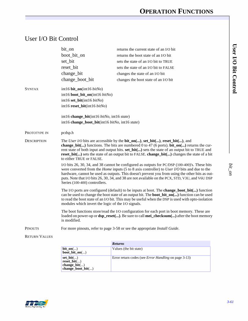
OPERATION FUNCTIONS
3-61
User I/O
Bit C
ontrol bit_on
User I/O Bit Control
bit_on returns the current state of an I/O bitboot_bit_on returns the boot state of an I/O bitset_bit sets the state of an I/O bit to TRUE
reset_bit sets the state of an I/O bit to FALSE
change_bit changes the state of an I/O bitchange_boot_bit changes the boot state of an I/O bit
SYNTAX int16 bit_on(int16 bitNo)int16 boot_bit_on(int16 bitNo)int16 set_bit(int16 bitNo)int16 reset_bit(int16 bitNo)
int16 change_bit(int16 bitNo, int16 state)int16 change_boot_bit(int16 bitNo, int16 state)
PROTOTYPE IN pcdsp.h
DESCRIPTION The User I/O bits are accessible by the bit_on(...), set_bit(...), reset_bit(...), and change_bit(...) functions. The bits are numbered 0 to 47 (6 ports). bit_on(...) returns the cur-rent state of both input and output bits. set_bit(...) sets the state of an output bit to TRUE and reset_bit(...) sets the state of an output bit to FALSE. change_bit(...) changes the state of a bit to either TRUE or FALSE.I/O bits 26, 30, 34, and 38 cannot be configured as outputs for PC/DSP (100-400)'s. These bits were converted from the Home inputs (5 to 8 axis controller) to User I/O bits and due to the hardware, cannot be used as outputs. This doesn't prevent you from using the other bits as out-puts. Note that I/O bits 26, 30, 34, and 38 are not available on the PCX, STD, V3U, and V6U DSP Series (100-400) controllers.
The I/O ports are configured (default) to be inputs at boot. The change_boot_bit(...) function can be used to change the boot state of an output bit. The boot_bit_on(...) function can be used to read the boot state of an I/O bit. This may be useful when the DSP is used with opto-isolation modules which invert the logic of the I/O signals.
The boot functions store/read the I/O configuration for each port in boot memory. These are loaded on power-up or dsp_reset(...). Be sure to call mei_checksum(...) after the boot memory is modified.
PINOUTS For more pinouts, refer to page 3-58 or see the appropriate Install Guide.
RETURN VALUES
Returnsbit_on(...)boot_bit_on(...)
Values (the bit state)
set_bit(...)reset_bit(...)change_bit(...)change_boot_bit(...)
Error return codes (see Error Handling on page 3-13)

OPERATION FUNCTIONS
3-62
Use
r I/
O B
it C
ontr
olbi
t_on
SAMPLE CODE This code checks the state of User I/O bit 0 and if bit 0 is on (high), turns on User I/O bit 8. If bit 0 is off (low) then User I/O bit 9 is turned on (high) for 1 sec and then turned off.
# include <stdio.h># include <dos.h># include "pcdsp.h"
int main(){
int16 val;
if (dsp_init(PCDSP_BASE)) /* any problems initializing? */return dsp_error; /* just terminate the program. */
init_io(0, IO_INPUT); /* configure port 0 as inputs */init_io(1, IO_OUTPUT); /* configure port 1 as outputs */set_io(1, 0); /* turn off all bits on Port 1 */
if (bit_on(0)) /* check state of input bit 0 */set_bit(8); /* turn on output bit 8 */
else{ change_bit(9, TRUE); /* turn on output bit 8 */
delay(1000);reset_bit(9); /* turn off output bit 9 */
}
return dsp_error ; /* global variable provided by the library */}
NOTES All the "bit" functions are just a simplified interface to set_io(...) and get_io(...). The functions make calls to set_io(...), set_boot_io(...), get_io(...), and get_boot_io(...) and do the bitwise manipulation of the 8-bit port value for you.

OPERATION FUNCTIONS
3-63
User I/O
Monitoring
set_io_mon_m
ask
User I/O Monitoring
set_io_mon_mask configure the DSP to monitor User I/Oio_changed returns the state of the DSP’s monitoring flagio_mon read the status of a monitored I/O portclear_io_mon reset the DSP’s I/O monitoring flag
SYNTAX int16 set_io_mon_mask(int16 port, int16 mask, int16 value)int16 io_changed(void)int16 io_mon(int16 port, int16 * status)int16 clear_io_mon(void)
PROTOTYPE IN pcdsp.h
DESCRIPTION The DSP can monitor up to 6 user I/O ports. If any of the specified bits change state the DSP continuously stores the changed bits into a status register and sets a flag. If interrupts are en-abled and an IRQ is configured then an interrupt will be generated to the PC.set_io_mon_mask(...) configures the DSP to monitor specific user I/O bits. The valid port range is from 0 to 5. The mask specifies to the DSP which bits to monitor. The value is com-pared by the DSP to the masked bits. If the masked bits are different from the specified value then the io_changed(...) flag is set.
io_changed(...) returns the state of the DSP’s I/O monitoring flag. If none of the specified bits have changed (all ports), then io_changed(...) returns FALSE. If any of the specified bits have changed (all ports) then io_changed(...) returns TRUE until clear_io_mon(...) is called.
io_mon(...) examines which bits have changed. The bits in status reflect which bit or bits have changed since the time the DSP set the io_changed(...) flag. Status keeps a continuous account of the specified bits that have changed by ORing the previous status with the latest I/O changes. The status may not be the same as the current state of the user I/O bits. get_io(...) should be used to read the current state of the User I/O bits for a specific port.
clear_io_mon(void) resets the monitor status for all ports and clears the io_changed(...) flag. This does not clear the mask or the value set by set_io_mon_mask(...). If the masked bits do not match the specified value, then the DSP will set the io_changed(...) flag TRUE within two samples.
I/O bits 26, 30, 34, and 38 cannot be configured as outputs for PC/DSP (100-400)'s. These bits were converted from the Home inputs (5 to 8 axis controller) to user I/O bits and due to the hardware, cannot be used as outputs. This doesn't prevent you from using the other bits as out-puts. I/O bits 26, 30, 34, and 38 are not available on the PCX, STD, V3U, V6U, 104X, and CPCI DSP Series (100-400) controllers, as well as the DSPpro-PC and DSPpro-VME controllers.
PINOUTS For more pinouts, refer to page 3-58 or see the appropriate Install Guide.
RETURN VALUES
SEE ALSO Interrupt Configuration, page 2-50.
Returnsset_io_mon_mask(...) Error return codes (see Error Handling on page 3-13)io_changed(void) Values (the state of I/O monitoring flag)io_mon(...)clear_io_mon(...)
Error return codes (see Error Handling on page 3-13)
OPERATION FUNCTIONS
3-64
Use
r I/
O M
onit
orin
gse
t_io
_mon
_mas
k
SAMPLE CODE This code configures the DSP to monitor user I/O bit 0. When the bit goes high, the DSP will set io_changed(...) to TRUE. Then the DSP I/O monitoring is disabled and io_changed(...) is cleared.
# include <stdio.h># include <dos.h># include "pcdsp.h"
# define PORT 0# define MASK 0x1
int main(){
int16 status;
if (dsp_init(PCDSP_BASE)) /* any problems initializing? */return dsp_error; /* just terminate the program. */
init_io(PORT, IO_INPUT); /* set port 0 to INPUT */
/* configure the DSP to watch bit 0 (active high) */set_io_mon_mask(PORT, MASK, 0x0);
while (!io_changed()) /* wait for bit 0 to go high */;
io_mon(PORT, &status); /* read the status of port 0’s I/O bits */printf(“\nStatus: %d”, status);set_io_mon_mask(PORT, 0x0, 0x0); /* disable the DSP I/O monitoring */clear_io_mon(); /* clear the io_changed flag */
return dsp_error ; /* global variable provided by the library */}

OPERATION FUNCTIONS
3-65
Analog Inputs
init_analog
Analog Inputs
init_analog initialize analog inputsget_analog get an analog input valuestart_analog write control word to A/D circuitryread_analog read analog input (15 usec after control word)
SYNTAX int16 init_analog(int16 channel, int16 differential, int16 bipolar)int16 get_analog(int16 channel, int16 * value)int16 start_analog(int16 channel)int16 read_analog(int16 * value)
PROTOTYPE IN pcdsp.h
DESCRIPTION The PC, PCX, STD, CPCI, V3U, V6U DSP Series controllers have 8 undedicated 12-bit analog input channels which are numbered 0 to 7. The DSPpro-Serial, DSPpro-PC, and DSPpro-VME also have 8 12-bit analog input channels. The 104, LC, and EXM DSP Series controllers and the SERCOS controllers do NOT have analog-to-digital converters. These functions are not appli-cable to the 104, LC, and EXM DSP Series.The analog-to-digital conversion operates by writing a control word to the A/D component, waiting at least 15 microseconds, and then reading the digital value. The analog inputs can be read by the DSP or directly from the Host CPU. To guarantee proper analog-to-digital conver-sions, the DSP and the PC cannot read the analog inputs at the same time.
If any axis is configured for servo on analog, axis analog, or on board jogging, then the Host CPU must NOT call the functions start_analog(...), read_analog(...) or get_analog(...).
start_analog(...) writes a control word to the A/D to begin the analog-to-digital conversion. Af-ter the conversion is complete, the digital value can be read with read_analog(...).
get_analog(...) calls start_analog(...), waits for a small period of time and then calls read_analog(...). get_analog(...) works well with most host processors, except for high speed CPUs (486, Pentiums etc.). If you see any inconsistencies with the get_analog(...) function then call start_analog(...), wait at least 15 microseconds, and then call read_analog(...). The ana-log signal is converted to a 12 bit digital value.
The default configuration for the analog inputs is 0 to +5 volts (0 to 4095), with single-ended inputs (8 channels). init_analog(...) configures an analog input channel for unipolar or bipolar and single-ended or differential operation.
When configured for bipolar operation, the input voltage range is -2.5 volts to +2.5 volts (-2048 to 2048). When configured for differential inputs (up to 4 channels), the analog circuitry reads difference between each pair of channels (0 and 1, 2 and 3, etc.) to filter out noise.
The even numbered channels (0, 2, 4, 6) are the (+) signals and the odd numbered channels (1, 3, 5, 7) are the (-) signals. The differential analog input value should be configured and read from the (+) channel (0, 2, 4, or 6).
The analog inputs are not buffered, so do not exceed +5 volts or -2.5 volts.
PINOUTS See next page. For more pinouts, see the appropriate Installation or User Guide.

OPERATION FUNCTIONS
3-66
Ana
log
Inpu
tsin
it_an
alog
RETURN VALUES
Table 3-10 Analog Input Connections
SAMPLE CODE This code monitors the analog input (channel 0), printing the value to the screen.
# include <stdio.h># include <conio.h># include "pcdsp.h"
int main(){
int16 val;
if (dsp_init(PCDSP_BASE)) /* any problems initializing? */return dsp_error; /* just terminate the program. */
while (!kbhit()){ get_analog(0, &val); /* read the A/D, channel 0 */
printf("Analog input channel 0: %d\r", val);}getch();
return dsp_error ; /* global variable provided by the library */}
Returnsinit_analog(...)get_analog(...)start_analog(...)read_analog(...)
Error return codes (see Error Handling on page 3-13)
Signal Header Pin Signal Header PinGND P8 1 Analog in 0 P8 4Analog GND P8 2 Analog in 1 P8 6-12 volts P8 5 Analog in 2 P8 8+12 volts P8 7 Analog in 3 P8 10+5 volts P8 9 Analog in 4 P8 12GND P8 19 Analog in 5 P8 14Analog GND P8 20 Analog in 6 P8 16
Analog in 7 P8 18
OPERATION FUNCTIONS
3-67
Axis A
nalog Inputs set_axis_analog
Axis Analog Inputs
set_axis_analog configure the DSP to read an analog input for an axisget_axis_analog read the axis analog configurationread_axis_analog read the axis analog input with the DSP
set_analog_channel set an analog channel for an axisset_boot_analog_channel set a boot analog channel for an axisget_analog_channel read the configured analog channel for an axisget_boot_analog_channel read the boot configured analog channel for an axis
SYNTAX int16 set_axis_analog(int16 axis, int16 state)int16 get_axis_analog(int16 axis, int16 * state)int16 read_axis_analog(int16 axis, int16 * value)int16 set_analog_channel(int16 axis, int16 channel, int16 differential, int16 bipolar)
int16 set_boot_analog_channel(int16 axis, int16 channel, int16 differential, int16 bipolar)int16 get_analog_channel(int16 axis, int16 * channel, int16 * differential, int16 * bipolar)int16 get_boot_analog_channel(int16 axis, int16 * channel, int16 * differential, int16 * bipolar)
PROTOTYPE IN pcdsp.h
DESCRIPTION The PC, PCX, STD, CPCI, V3U, V6U DSP Series controllers have 8 undedicated 12-bit analog input channels which are numbered 0 to 7. The DSPpro-Serial, DSPpro-PC, and DSPpro-VME also have 8 twelve-bit analog input channels. The 104, LC, and EXM DSP Series controllers and the SERCOS controllers do NOT have analog-to-digital converters. These functions are not ap-plicable to the 104, LC, and EXM DSP Series.The analog-to-digital conversion operates by writing a control word to the A/D component, waiting at least 15 microseconds, and then reading the digital value. The analog inputs can be read by the DSP or directly from the Host CPU. To guarantee proper analog-to-digital conver-sions, the DSP and the PC cannot read the analog inputs at the same time. If any axis is config-ured for servo-on-analog, axis analog, or on-board jogging, then the Host CPU must NOT call the functions start_analog(...), read_analog(...) or get_analog(...).
set_axis_analog(...) configures the DSP to read an axis’ analog input each sample. The auto-matic axis analog reading is enabled when state = TRUE and disabled when state = FALSE. One channel is read per axis. get_axis_analog(...) reads an axis’ analog configuration.
read_axis_analog(...) reads the axis analog input from the DSP. The analog input channel, and its configuration are set by set_analog_channel(...). The default configuration is axis = chan-nel, differential = FALSE, and bipolar = FALSE. Be sure to configure only one analog input channel per axis.
Using the axis analog configuration it is possible for the PC to read an analog channel with read_axis_analog(...) when an axis is configured for servo on analog or jog_axis(...).
If bipolar = TRUE, the input voltage range is -2.5 volts to +2.5 volts (-2048 to 2047). If differential = TRUE, the analog circuitry reads difference between each pair of channels (0 and 1, 2 and 3, etc.) to filter out noise. When configured for differential, the analog input value should be configured and read from the (+) channels (0, 2, 4, 6). The odd numbered channels (1, 3, 5, 7) are the (-) signals.
OPERATION FUNCTIONS
3-68
Axi
s A
nalo
g In
puts
set_
axis
_ana
log
set_analog_channel(...) also configures the analog input channel when an axis is configured for servo on analog or jogging. This is very useful in systems that need to switch between sev-eral analog input channels. get_analog_channel(...) reads the current A/D configuration.
The analog inputs are not buffered, so the controller will be damaged if input voltages ex-ceed+5 volts or -2.5 volts. Also, do not apply any voltage to the inputs with the controller pow-ered off.
SEE ALSO init_analog(...), get_analog(...), start_analog(...), read_analog(...), jog_axis(...), set_feedback(...)
PINOUTS See the appropriate Install Guide.
RETURN VALUES
SAMPLE CODE This code configures the DSP to read analog input channel 0 and prints the value to the screen.
# include <stdio.h># include <conio.h># include "pcdsp.h"
int main(){
int16 val;
if (dsp_init(PCDSP_BASE)) /* any problems initializing? */return dsp_error; /* just terminate the program. */
/* configure the DSP to read axis 0’s analog input every sample */set_axis_analog(0, TRUE);
while (!kbhit()){ read_axis_analog(0, &val); /* read axis 0’s analog input */
printf("Analog input channel 0: %d\r", val);}return dsp_error ; /* global variable provided by the library */
}
Returnsset_axis_analog(...)get_axis_analog(...)read_axis_analog(...)set_analog_channel(...)set_boot_analog_channel(...)get_analog_channel(...)get_boot_analog_channel(...)
Error return codes (see Error Handling on page 3-13)

OPERATION FUNCTIONS
3-69
Axis A
nalog Outputs
set_dac_channel
Axis Analog Outputs
set_dac_channel configure the DAC channel for an axisset_boot_dac_channel configure the boot DAC channel for an axisget_dac_channel read the configured DAC channel for an axisget_boot_dac_channel read the configured boot DAC channel for an axisset_dac_output set the value of the 16-bit analog outputget_dac_output get the 16-bit value of the analog output
SYNTAX int16 set_dac_channel(int16 axis, int16 channel)int16 set_boot_dac_channel(int16 axis, int16 channel)int16 get_dac_channel(int16 axis, int16 * channel)int16 get_boot_dac_channel(int16 axis, int16 * channel)
int16 set_dac_output(int16 axis, int16 voltage)int16 get_dac_output(int16 axis, int16 * voltage)
PROTOTYPE IN pcdsp.h
DESCRIPTION The DSP controller has one 16-bit digital-to-analog converter per axis. set_dac_channel(...) configures the DAC channel for an axis. The default configuration is axis = channel. This is very useful in systems that need to switch between several feedback devices or several PID algorithms.
get_dac_channel(...) reads the current DAC configuration. Be sure to configure only one axis per DAC output channel.
Normally the analog outputs are controlled by the DSP with the PID algorithm. The analog out-puts can also be controlled directly from the CPU with set_dac_output(...). To control the an-alog outputs directly from the CPU, disable PID control by setting the PID filter parameters to zero with set_filter(...) or by calling controller_idle(...).
Valid ranges for voltage are: +32767 (10V) to -32768 (-10V). get_dac_output(...) can be used to read the value of the output voltage during run mode or idle mode.
SEE ALSO controller_idle(...), set_filter(...)
RETURN VALUES
Returnsset_dac_channel(...)set_boot_dac_channel(...)get_dac_channel(...)get_boot_dac_channel(...)set_dac_output(...)get_dac_output(...)
Error return codes (see Error Handling on page 3-13)
OPERATION FUNCTIONS
3-70
Axi
s A
nalo
g O
utpu
tsse
t_da
c_ch
anne
l
SAMPLE CODE This code disables PID control and sets an analog output of 1V for axis 0 until a key is pressed. The analog output voltage is then set to zero volts and PID control is re-enabled.
# include "pcdsp.h"
int main(){
if (dsp_init(PCDSP_BASE)) /* any problems initializing? */return dsp_error; /* just terminate the program. */
controller_idle(0); /* trigger an ABORT_EVENT */set_dac_output(0, 3276); /* set analog output to 1 volt */getch() /* wait for a key press */
set_dac_output(0, 0); /* set analog output to 0 volts */controller_run(0); /* re-enable PID control */
return dsp_error ; /* global variable provided by the library */}
NOTES set_dac_output(...) can be used with open-loop velocity control, force control, or other analog operated devices. When used with voltage (velocity) controlled amplifiers or step motors the analog output corresponds to the motor velocity. When used with current controlled amplifiers, the analog output corresponds to the torque applied to the motor.The set_dac_output(...) function modifies the offset filter parameter, so make sure to set the analog output back to zero before the PID is re-enabled.
OPERATION FUNCTIONS
3-71
Counter/T
imer
init_timer
Counter/Timer
init_timer initialize the undedicated 8254 counter/timerset_timer set a timer valueget_timer get a timer value
SYNTAX int16 init_timer(int16 channel, int16 mode)int16 set_timer(int16 channel, unsigned16 t)int16 get_timer(int16 channel, unsigned16 * t)
PROTOTYPE IN pcdsp.h
DESCRIPTION The PC, PCX, STD, V3U, V6U, CPCI, 104X DSP Series controllers and the DSPpro-Serial, DSP-pro-PC, and DSPpro-VME have an undedicated 82C54 counter/timer. The 104, LC, and EXM DSP Series do NOT have an undedicated 82C54 counter/timer. These functions are not appli-cable to the 104, LC, and EXM DSP Series.The 82C54 supports several counter modes, which are configured with the init_timer(...) func-tion. The modes are defined:
MODE 0: INTERRUPT ON TERMINAL COUNT
Mode 0 is typically used for event counting. After the Control Word is written, OUT is initially low, and will remain low until the Counter reaches zero. OUT then goes high and remains high until a new count or a new Mode 0 Control Word is written into the Counter.
GATE = 1 enables countingGATE = 0 disables counting
GATE has no effect on OUT.
MODE 1: HARDWARE RETRIGGERABLE ONE-SHOT
OUT will be initially high. OUT will go low on the CLK pulse following a trigger to begin the one-shot pulse, and will remain low until the Counter reaches zero. OUT will then go high and remain high until the CLK pulse after the next trigger.
MODE 2: RATE GENERATOR
This Mode functions like a divide-by-N counter. It is typically used to generate a real-time Clock interrupt. OUT will initially be high. When the initial count decrements to 1, OUT goes low for one CLK pulse. OUT then goes high again, the Counter reloads the initial count and the process is repeated. Mode 2 is periodic; the same sequence is repeated indefinitely. For an ini-tial count of N, the sequence repeats every N CLK cycles.
GATE = 1 enables countingGATE = 0 disables counting
If GATE goes low during an output pulse, OUT is set high immediately. A trigger reloads the Counter with the initial count on the next CLK pulse; OUT goes low N CLK pulses after the trigger. Thus the GATE input can be used to synchronize the Counter.
MODE 3: SQUARE WAVE MODE
Mode 3 is typically used for Baud rate generation. Mode 3 is similar to Mode 2 except for the duty cycle of OUT. OUT will initially be high. When half the initial count has expired, OUT goes low for the remainder of the count. Mode 3 is periodic; the sequence above is repeated indefinitely. An initial count of N results in a square wave with a period of N CLK cycles.
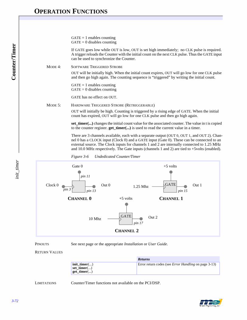
OPERATION FUNCTIONS
3-72
Cou
nter
/Tim
erin
it_tim
er
GATE = 1 enables countingGATE = 0 disables counting
If GATE goes low while OUT is low, OUT is set high immediately; no CLK pulse is required. A trigger reloads the Counter with the initial count on the next CLK pulse. Thus the GATE input can be used to synchronize the Counter.
MODE 4: SOFTWARE TRIGGERED STROBE
OUT will be initially high. When the initial count expires, OUT will go low for one CLK pulse and then go high again. The counting sequence is “triggered” by writing the initial count.
GATE = 1 enables countingGATE = 0 disables counting
GATE has no effect on OUT.
MODE 5: HARDWARE TRIGGERED STROBE (RETRIGGERABLE)OUT will initially be high. Counting is triggered by a rising edge of GATE. When the initial count has expired, OUT will go low for one CLK pulse and then go high again.
set_timer(...) changes the initial count value for the associated counter. The value in t is copied to the counter register. get_timer(...) is used to read the current value in a timer.
There are 3 channels available, each with a separate output (OUT 0, OUT 1, and OUT 2). Chan-nel 0 has a CLOCK input (Clock 0) and a GATE input (Gate 0). These can be connected to an external source. The Clock inputs for channels 1 and 2 are internally connected to 1.25 MHz and 10.0 MHz respectively. The Gate inputs (channels 1 and 2) are tied to +5volts (enabled).
Figure 3-6 Undedicated Counter/Timer
PINOUTS See next page or the appropriate Installation or User Guide.
RETURN VALUES
LIMITATIONS Counter/Timer functions not available on the PCI/DSP.
Returnsinit_timer(...)set_timer(...)get_timer(...)
Error return codes (see Error Handling on page 3-13)
Gate 0
CHANNEL 0
pin 11
Clock 0 Out 0pin 13pin 3
+5 volts
CHANNEL 1
1.25 Mhz Out 1pin 15
+5 volts
CHANNEL 2
10 Mhz Out 2pin 17
GATE
GATE

OPERATION FUNCTIONS
3-73
Master/Slave
mei_link
Master/Slave
mei_link connect 2 axes together with a ratioendlink disconnect 2 axes
SYNTAX int16 mei_link(int16 master, int16 slave, double ratio, int16 source)int16 endlink(int16 slave)
PROTOTYPE IN pcdsp.h
DESCRIPTION mei_link(...) configures 2 axes for master/slave operation. When axes are linked, the DSP cal-culates the slave’s control position from the master’s change in position (either command or actual) multiplied by some ratio every sample. The DSP handles the slaving, so the host pro-cessor is then able to proceed with no additional overhead. The parameters are:
Use the #defines LINK_ACTUAL and LINK_COMMAND to specify whether the link is based on the actual or command position of the master axis. When the axes are linked, the slave axis be-gins its link from its current position (keeping the difference in positions between the master and the slave as an offset).
mei_link(...) can be called when the master is at any position, when the master is moving, or when the slave is moving. The ratio can be changed on the fly by calling mei_link(...) with a new ratio.
To end a link when the master or slave is not moving, simply call endlink(...). To end a link when the master or slave is moving call mei_link(...) with ratio = 0.0, then after the slave has stopped moving, call endlink(...).
Be careful when linking moving axes or changing the ratio, the motors may not be able to keep up with abrupt changes. When axes are linked do not call set_position(...) on the linked axes. Watch out for large link ratios. A large ratio will cause any perturbations on the master axis to be magnified by the ratio and applied to the slave. Also, watch out for round-off errors when using fractional ratios. The resolution of the DSP’s ratio is 16 bit whole and 16 bit fractional.
When axes are linked together, motion can still be commanded on both axes. This feature is very useful for blending motion profiles.
RETURN VALUES
Table 3-11 Master/Slave Parameters
Parameter Description
master controlling axisslave axis to follow the masterratio ratio of the slave/master operationsource LINK_ACTUAL or
LINK_COMMAND
Returnsmei_link(...)endlink(...)
Error return codes (see Error Handling on page 3-13)

OPERATION FUNCTIONS
3-74
Mas
ter/
Slav
em
ei_l
ink
SAMPLE CODE This code links the command position of axis 1 to axis 0. The DSP handles the slaving, so the host processor is then able to proceed with no overhead.
# include "pcdsp.h"
int main(){
if (dsp_init(PCDSP_BASE)) /* any problems initializing? */return dsp_error; /* just terminate the program. */
/* positionally link master axis 0 to axis 1 with a 2:1 ratio */mei_link(0, 1, 2.0, LINK_COMMAND);
/* move a relative distance and wait for completion */r_move(0, 1000.0, 2000.0, 20000.0);
endlink(1); /* disable master slave control */
return dsp_error ; /* global variable provided by the library */}

OPERATION FUNCTIONS
3-75
Master/C
am set_cam
Master/Cam
set_cam configure 2 axes for master/cam operationset_boot_cam configure 2 axes for master/cam operation at boot
SYNTAX int16 set_cam(int16 master_axis, int16 cam_axis, int16 cam, int16 source)int16 set_boot_cam(int16 master_axis, int16 cam_axis, int16 cam, int16 source)
PROTOTYPE IN pcdsp.h
DESCRIPTION Use set_cam(...) to configure 2 axes for master/cam operation. Camming is enabled when cam = TRUE, and disabled when cam = FALSE. When source = CAM_ACTUAL, the cam_axis’ mo-tion profile will be executed based on the rate of change of the master_axis’ actual encoder in-put. When source = CAM_COMMAND, the cam_axis’ motion profile will be executed based on the rate of change of the master_axis’ command position.Tn = Tn-1 + FdSpd Tn is the time at sample nAn = An-1 + FdSpd * J J is the jerkVn = Vn-1 + FdSpd * An An is the acceleration at sample nXn = Xn-1 + FdSpd * Vn Vn is the velocity at sample n
Xn is the command position at sample nFdSpd is the feed speed
Motion profiles are created on the cam_axis in the same way that motion profiles are created on non-cammed axes, except that the execution rate of the motion profile (for the cam_axis) is based on the absolute value of the velocity of the master_axis, and not the time (of the master_axis).
When configuring a master_axis for camming with source = CAM_ACTUAL, we are really just creating a velocity-based encoder. Be sure not to mix a cammed master_axis with a dual-loop velocity_axis.
The boot functions store/read the feedback configuration for each axis in boot memory. These are loaded on power-up or dsp_reset(...). Be sure to call mei_checksum(...) after the boot memory is modified.
RETURN VALUES
SAMPLE CODE This code configures 2 axes for camming, and executes a motion profile on the cam.# include "pcdsp.h"int main(){
if (dsp_init(PCDSP_BASE)) /* any problems initializing? */return dsp_error; /* just terminate the program. */
set_cam(0, 1, TRUE, CAM_ACTUAL); /* axis 0 = master, axis 1 = cam *//* load a trapezoidal profile on the cam axis */
start_r_move(1, 2000., 5000., 10000.);
set_velocity(0, 1250.); /* move the master at 1 count/sample */while (!motion_done(1)) /* wait for the cam profile completion */
;set_velocity(0, 0.); /* stop the master axis */
Returnsset_cam(...)set_boot_cam(...)
Error return codes (see Error Handling on page 3-13)

OPERATION FUNCTIONS
3-76
Mas
ter/
Cam
set_
cam
return dsp_error ; /* global variable provided by the library */}
NOTES When using camming for the first time, rotate the master encoder manually to get a feel for the response of the profile on the cam axis.
OPERATION FUNCTIONS
3-77
Feed Speed O
verride dsp_feed_rate
Feed Speed Override
dsp_feed_rate change the feed rate for all axesaxis_feed_rate change the feed rate for one axis
SYNTAX int16 dsp_feed_rate(double feed_rate)int16 axis_feed_rate(int16 axis, double feed_rate)
PROTOTYPE IN pcdsp.h
DESCRIPTION dsp_feed_rate(...) sets the feed_rate of all the axes. axis_feed_rate(...) sets the feed_rate of one axis. The velocity, acceleration and jerk are increased/decreased by a feed_rate factor. The range of the feed_rate is from a complete stop (feed_rate = 0.0) up to twice the speed (feed_rate = 2.0). feed_rate is a percentage of the command velocity, acceleration, and the jerk. For ex-ample, a value of 0.5 (50%) runs an axis at half speed.Every sample the DSP updates the trajectory:
Tn = Tn-1 + FdSpd Tn is the time at sample nAn = An-1 + FdSpd * J J is the jerkVn = Vn-1 + FdSpd * An An is the acceleration at sample nXn = Xn-1 + FdSpd * Vn Vn is the velocity at sample n
Xn is the command position at sample nFdSpd is the feed speed
RETURN VALUES
SAMPLE CODE This code reads the states of the first 2 bits of user I/O (configured as inputs) to change the feed speed of all the axes. Input bit 0 decreases the speed by 1% and input 1 increases the speed by 1% each time the loop is updated. The program ends when a key is pressed.
# include "pcdsp.h"
int main(){
double rate = 1.0;
if (dsp_init(PCDSP_BASE)) /* any problems initializing? */return dsp_error; /* just terminate the program. */
init_io(0, IO_INPUT); /* configure port 0 as inputs */
while (! kbhit()){ if (bit_on(0) && rate < 2.0)
rate += .01; /* increase the rate by 1% */if (bit_on(1) && rate > 0.0)
rate -= .01; /* decrease the rate by 1% */dsp_feed_rate(rate); /* change the feed rate */
}getch();
return dsp_error ; /* global variable provided by the library */}
Returnsdsp_feed_rate(...)axis_feed_rate(...)
Error return codes (see Error Handling on page 3-13)

OPERATION FUNCTIONS
3-78
Fee
d Sp
eed
Ove
rrid
eds
p_fe
ed_r
ate
NOTES The feed rate should be changed slowly to avoid abrupt velocity changes. A common applica-tion of the feed speed override is to pause the motion. By reducing the feed speed to zero the motion will be halted and can be continued by increasing the feed rate back to 100%.
OPERATION FUNCTIONS
3-79
Position L
atching arm
_latch
Position Latching
arm_latch enables the DSP interrupt and resets a position-ready flaglatch_status returns FALSE until the latched positions are readyget_latched_position returns the latched position of an axislatch initiate a position latch from software
SYNTAX int16 arm_latch(int16 enable)int16 latch_status(void)int16 get_latched_position(int16 axis, double * position)int16 latch(void)
PROTOTYPE IN pcdsp.h
DESCRIPTION arm_latch(...) configures the DSP to capture the actual positions of all the axes when a DSP interrupt is generated. Latching is enabled when enable = TRUE, and disabled when enable = FALSE. The position latching is activated when user I/O bit 22 transitions from a high (+5V) to a low signal (0V). All of the axes actual positions are captured within 4 microseconds. latch_status(...) returns TRUE when the position latch is complete. get_latched_position(...) retrieves the latched position of an axis.To generate a position latch from software, initialize port 2 as outputs with init_io(...). Then call arm_latch(...) and latch(...). latch(...) tries to set user I/O bit 22 low, generating a DSP in-terrupt. If user I/O bit 22 is not pulled low then the latch will fail. Make sure there are no exter-nal connections to user I/O bit 22.
SERCOS The position latching functions are applicable to SERCOS controllers. However, the actual po-sition capture time is based on the SERCOS loop update rate. Many SERCOS drives support local internal position latching. For more information, please consult the drive manufacturer’s documentation.
PINOUTS See the appropriate Install Guide.
RETURN VALUES
SEE ALSO init_io(...)
Returnsarm_latch(...) Error return codes (see Error Handling on page 3-13)latch_status(...) Value (Returns FALSE until the position’s latch finishes)get_latched_position(...)latch(...)
Error return codes (see Error Handling on page 3-13)
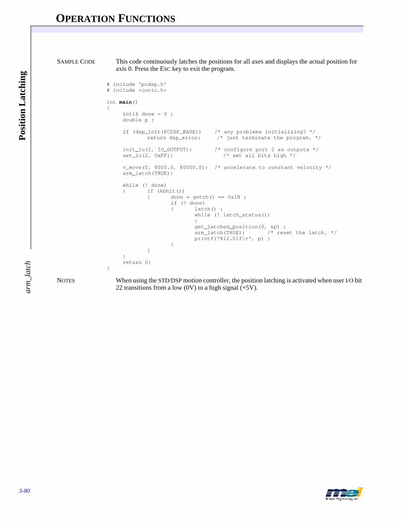
OPERATION FUNCTIONS
3-80
Pos
itio
n L
atch
ing
arm
_lat
ch
SAMPLE CODE This code continuously latches the positions for all axes and displays the actual position for axis 0. Press the ESC key to exit the program.
# include "pcdsp.h"# include <conio.h>
int main(){
int16 done = 0 ;double p ;
if (dsp_init(PCDSP_BASE)) /* any problems initializing? */return dsp_error; /* just terminate the program. */
init_io(2, IO_OUTPUT); /* configure port 2 as outputs */set_io(2, 0xFF); /* set all bits high */
v_move(0, 8000.0, 80000.0); /* accelerate to constant velocity */arm_latch(TRUE);
while (! done){ if (kbhit())
{ done = getch() == 0x1B ;if (! done){ latch() ;
while (! latch_status());get_latched_position(0, &p) ;arm_latch(TRUE); /* reset the latch. */printf("%12.0lf\r", p) ;
}}
}return 0;
}
NOTES When using the STD/DSP motion controller, the position latching is activated when user I/O bit 22 transitions from a low (0V) to a high signal (+5V).
OPERATION FUNCTIONS
3-81
On-B
oard Jogging jog_axis
On-Board Jogging
jog_axis enable on-board analog-controlled jogging for one axis
SYNTAX int jog_axis(int axis, int jog_channel, int c, int d, double m1, double m2, int enable)
PROTOTYPE IN pcdsp.h
DESCRIPTION The PC, PCX, STD, CPCI, V3U, V6U DSP Series controllers have 8 undedicated 12-bit analog input channels which are numbered 0 to 7. The DSPpro-Serial, DSPpro-PC, and DSPpro-VME also have 8 12-bit analog input channels. The 104, LC, and EXM DSP Series controllers and the SERCOS controllers do NOT have analog-to-digital converters. These functions are not appli-cable to the 104, LC, EXM, and SERCOS DSP Series.The analog-to-digital conversion operates by writing a control word to the A/D component, waiting at least 15 microseconds, and then reading the digital value. The analog inputs can be read by the DSP or directly from the Host CPU. To guarantee proper analog-to-digital conver-sions, the DSP and the PC cannot read the analog inputs at the same time. If any axis is config-ured for servo-on-analog, axis analog, or onboard jogging, then the Host CPU must not call the functions start_analog(...), read_analog(...) or get_analog(...).
jog_axis(...) configures the DSP to control an axis’ command velocity based on an analog in-put. jog_channel (0, 1, or 2) indicates the firmware jog channel. Note that you can map any of the 8 analog channels to any axis, but you must map a jog channel to axes 0, 1 or 2 only- you can only map the jog channels to the first 3 axes. c indicates the analog center value corre-sponding to zero velocity. d indicates the deadband in analog counts. m1 is the linear velocity term. m2 is the cubic velocity term. Jogging is enabled if enable = TRUE and disabled if enable = FALSE. No more than 3 axes can be configured for jogging simultaneously.
Each sample the DSP calculates the command velocity based on the analog input and the jog_axis(...) parameters:
If the A/D value > (center + deadband), then J = A/D value - center - deadbandIf the A/D value < (center - deadband), then J = A/D value - center + deadbandIf (center + deadband) > A/D value > (center - deadband), then J = 0
velocity (counts/sec) = (linear term * J/65536 + cubic term * 3.632 * 10-12 * J3) * sample ratewhere, c = center
d = deadband linear term = m1cubic term = m2default sample rate = 1250 samples/sec
The analog input channel, and its configuration are set by set_analog_channel(...). The default configuration is axis = channel, differential = FALSE, and bipolar = FALSE. Be sure to config-ure only one analog input channel per axis. set_analog_channel(...) is very useful in systems that need to switch between several analog input channels.
PINOUTS See the appropriate Install Guide.
RETURN VALUES
SEE ALSO start_analog(...), read_analog(...), get_analog(...), set_analog_channel(...), get_axis_analog(...), dsp_sample_rate(...), set_sample_rate(...)
Returnsjog_axis(...) Error return codes (see Error Handling on page 3-13)

OPERATION FUNCTIONS
3-82
On-
Boa
rd J
oggi
ngjo
g_ax
is
SAMPLE CODE This code initializes analog input channels 0, 1, and 2 for unipolar onboard jogging.
# include <stdio.h># include "pcdsp.h"
#define X 0#define Y 1#define Z 2
#define XJOG 0#define YJOG 1#define ZJOG 2
#define XANALOGCHANNEL 0#define YANALOGCHANNEL 1#define ZANALOGCHANNEL 2
#define XCENTER 2048#define YCENTER 2048#define ZCENTER 2048
#define XDEADBAND 5#define YDEADBAND 20#define ZDEADBAND 50
#define XLINEAR 10#define YLINEAR 100#define ZLINEAR 1000
#define XCUBIC 10#define YCUBIC 50#define ZCUBIC 100
int main(){
if (dsp_init(PCDSP_BASE)) /* any problems initializing? */return dsp_error; /* just terminate the program. */
set_analog_channel(X, XANALOGCHANNEL, FALSE, FALSE);set_analog_channel(Y, YANALOGCHANNEL, FALSE, FALSE);set_analog_channel(Z, ZANALOGCHANNEL, FALSE, FALSE);
jog_axis(X, XJOG, XCENTER, XDEADBAND, XLINEAR, XCUBIC, TRUE);jog_axis(Y, YJOG, YCENTER, YDEADBAND, YLINEAR, YCUBIC, TRUE);jog_axis(Z, ZJOG, ZCENTER, ZDEADBAND, ZLINEAR, ZCUBIC, TRUE);
return dsp_error ; /* global variable provided by the library */}
OPERATION FUNCTIONS
3-83
Multiple C
ontrollers
Multiple Controllers
m_setup initialize pointers to access multiple motion controller boards
m_board switch pointers to access a particular boardm_axis switch pointers to access a particular axis
SYNTAX int16 m_setup(int16 boards, int16 * controller_addresses)int16 m_board(int16 board_number)int16 m_axis(int16 actual_axis)
PROTOTYPE IN pcdsp.h, mboard.h
DESCRIPTION The controller maintains a structure called DSP which contains information pertaining to the base I/O address, and a bunch of other stuff. A library variable called dspPtr contains a pointer to the default DSP structure. By varying this pointer, we can get the library to use multiple con-trollers. In version 2.5, individual axes can be enabled or disabled with software. It is now pos-sible to configure a controller with non-sequential axes.Use m_setup(...) instead of dsp_init(...) to initialize several controllers. Simply create an array where each element contains the base I/O address of a controller. Pass that array to this func-tion, and m_setup(...) will perform the appropriate software initialization. The actual_axes will be numbered according to the order of the controllers in the controller_addresses array and the number of axes for each controller found by dsp_axes(...).
m_board(...) modifies the dspPtr to point to a particular board. m_axis(...) sets the dspPtr to point to the desired controller board and returns the physical axis on that controller. The func-tion m_axis(…) does not support non-sequential axes. The value returned by m_axis(...) should be used as the axis parameter for other library functions. We recommend using m_board(…) to switch between controllers.
SEE ALSO dsp_axes(...), set_axis(…), get_axis(…)
RETURN VALUES
SAMPLE CODE This code initializes a 3-axis controller and a 4-axis controller. Both controllers are reset and the actual positions are read.
# include "pcdsp.h"# include “mboard.h”# define BOARDS 2int main(){
int16 i, axes = 0, addresses[] = {0x300, 0x310};double actual;
if (m_setup(BOARDS, addresses)) /* any problems initializing? */return dsp_error; /* just terminate the program. */
for (i = 0; i < BOARDS; i++){ m_board(i);
dsp_reset();axes += dsp_axes();
}
Returnsm_setup(...)m_board(...)m_axis(...)
Error return codes (see Error Handling on page 3-13)
OPERATION FUNCTIONS
3-84
Mul
tipl
e C
ontr
olle
rs
for (i = 0; i < axes; i++){ get_position(m_axis(i), &actual);
printf(“\nAxis: %d Actual: %lf”, i, actual);}return dsp_error ; /* global variable provided by the library */
}
OPERATION FUNCTIONS
3-85
Trajectory F
rames
Trajectory Frames
dsp_dwell delay execution of a frame for an axisdsp_position update command position and delay execution of next framedsp_velocity update velocity and delay execution of next framedsp_accel update accel and delay execution of next framedsp_jerk update jerk and delay execution of next framedsp_end_sequence clear an axis’ in_sequence status bit
SYNTAX int16 dsp_dwell(int16 axis, double duration)int16 dsp_position(int16 axis, double position, double duration)int16 dsp_velocity(int16 axis, double velocity, double duration)int16 dsp_accel(int16 axis, double accel, double duration)
int16 dsp_jerk(int16 axis, double jerk, double duration)int16 dsp_end_sequence(int16 axis)
PROTOTYPE IN pcdsp.h
DESCRIPTION dsp_dwell(...) downloads a frame to the DSP that does nothing for a set period of time. Its effect is to stall the execution of the next frame in the buffer for a given duration. The valid range for the duration is from zero seconds (1 sample) to (2^32/sample_rate) seconds. The units for du-ration are seconds.dsp_position(...) downloads a frame to the DSP that updates an axis’ command position and delays the execution of the next frame in the buffer for given duration. Be careful, changes in the command position will cause the motor to jump immediately to the new position.
dsp_velocity(...) downloads a frame to the DSP that updates an axis’ command velocity and de-lays the execution of the next frame in the buffer for given duration. The direction is deter-mined by the sign of the velocity.
dsp_accel(...) downloads a frame to the DSP that updates an axis’ command acceleration and delays the execution of the next frame in the buffer for given duration. The direction is deter-mined by the sign of the acceleration.
dsp_jerk(...) downloads a frame to the DSP that updates an axis’ command jerk and delays the execution of the next frame in the buffer for given duration. The direction is determined by the sign of the jerk.
dsp_end_sequence(...) downloads a frame to the DSP that clears an axis’ in_sequence status bit. dsp_dwell(...), dsp_position(...), dsp_velocity(...), dsp_accel(...), and dsp_jerk(...) download a single frame with a time trigger. The DSP executes these single frames from its buffer and updates the status bits based on the execution of the frames. An axis’ in_sequence bit is turned on when a frame is executed.
The command position resolution is 32 bits whole and 32 bits fractional. The actual position resolution is 32 bits whole. The command velocity, acceleration, and jerk all have a resolution of 16 bits whole and 32 bits fractional. On every sample, the DSP updates the trajectory.

OPERATION FUNCTIONS
3-86
Tra
ject
ory
Fra
mes
To have the frame exit after 1 sample (the shortest period possible), use duration = 0. For ex-ample, a rudimentary trapezoidal profile motion could be performed by:
dsp_accel(axis, accel, time); /* begin acceleration */dsp_accel(axis, 0, slewtime); /* stop accelerating */dsp_accel(axis, -accel, time); /* decelerate */dsp_accel(axis, 0, 0); /* zero the acceleration */dsp_velocity(axis, 0, 0); /* zero the command velocity. */dsp_end_sequence(axis); /* clear the in_sequence bit */
dsp_velocity(...) is used here to eliminate the possibility of the motor continuing to move due to acceleration/deceleration round-off. In this example, because the accel and decel times are the same, the round-off is 0, but its always a good idea to zero the velocity when you're done.
RETURN VALUES
SAMPLE CODE This code loads a sequence of frames that accelerates and decelerates for specific durations. The final command position is calculated by: dist = vt + .5(a*t*t)
# include <stdio.h># include "pcdsp.h"
int main(){
if (dsp_init(PCDSP_BASE)) /* any problems initializing? */return dsp_error; /* just terminate the program. */
set_position(0, 0.0);
dsp_accel(0, 400, 4.0); /* accelerate for 4.0 seconds */dsp_accel(0, -400, 8.0); /* decelerate for 8.0 seconds */dsp_accel(0, 400, 4.0); /* accelerate for 4.0 seconds */dsp_accel(0, 0.0, 0.0); /* zero acceleration */dsp_velocity(0, 0.0, 0.0); /* zero velocity */dsp_position(0, 0.0, 0.0); /* set command to correct for roundoff */
return dsp_error ; /* global variable provided by the library */}
Table 3-12 How the DSP Updates the Trajectory
Expression Variable Definitions
Tn = Tn-1 + FdSpd Tn is the time at sample n
An = An-1 + FdSpd * J J is the command jerk
Vn = Vn-1 + FdSpd * An An is the command acceleration at sample n
Xn = Xn-1 + FdSpd * Vn Vn is the command velocity at sample n
Xn is the command position at sample n
FdSpd is the feed speed
Returnsdsp_dwell(...)dsp_position(...)dsp_velocity(...)dsp_accel(...)dsp_jerk(...)dsp_end_sequence(...)
Error return codes (see Error Handling on page 3-13)

OPERATION FUNCTIONS
3-87
I/O F
rames
I/O Frames
dsp_io_frame update the state of an 8-bit user I/O portdsp_io_trigger delay execution of next frame until bit level changes to statedsp_io_trigger_mask delay execution of next frame until the masked port changes
to state
SYNTAX int16 dsp_io_frame(int16 axis, int16 port, int16 ormask, int16 andmask)int16 dsp_io_trigger(int16 axis, int16 bit, int16 state)int16 dsp_io_trigger_mask(int16 axis, int16 port, int16 mask, int16 state)
PROTOTYPE IN pcdsp.h
DESCRIPTION dsp_io_frame(...) downloads a frame that modifies a user I/O output port according to the or-mask and the andmask. The port specified will be bitwise ORed with the ormask and then bit-wise ANDed with the andmask. Because this function downloads a frame, the port won't be modified until the DSP executes this frame.dsp_io_trigger(...) downloads a frame to the DSP that does nothing until a specified user I/O bit becomes the level specified by the state parameter. The state is either TRUE or FALSE, which indicates the active level.
dsp_io_trigger_mask(...) downloads a frame that delays execution of the next frame in the list until the masked bit(s) correspond to the logic of state. The bit(s) are decoded by the user I/O port, bitwise ORed with the mask. If state = TRUE, the next frame is triggered when all the masked bit(s) are high (+5 volts). If state = FALSE, the next frame is triggered if any masked bit is low (0 volts).
PINOUTS See the appropriate Install Guide.
RETURN VALUES
SAMPLE CODE This code loads a dsp_io_trigger(...) frame and a dsp_dwell(...) frame for axis 0 followed by a trapezoidal profile move. When bit 0 goes high, then the DSP executes the profile on axis 0.
# include <stdio.h># include "pcdsp.h"
int main(){
if (dsp_init(PCDSP_BASE)) /* any problems initializing? */return dsp_error; /* just terminate the program. */
init_io(0, IO_OUTPUT); /* configure port 0 as outputs */set_io(0, 0); /* set all bits on port 0 to low */
dsp_io_trigger(0, 0, TRUE); /* wait for bit 0 to go high */dsp_dwell(0, 5.0); /* wait for 5 seconds */start_move(0, 4000.0, 1000.0, 1000.0);
getch(); /* wait for a key */set_bit(0); /* set bit 0 high */
return dsp_error ; /* global variable provided by the library */}
Returnsdsp_io_frame(...)dsp_io_trigger(...)dsp_io_trigger_mask(...)
Error return codes (see Error Handling on page 3-13)

OPERATION FUNCTIONS
3-88
Pos
itio
n-T
rigg
ered
Fra
mes
Position-Triggered Frames
dsp_position_trigger generate an action when a position is exceededdsp_actual_position_trigger
delays the next frame until an actual position is exceededdsp_command_position_trigger
delays the next frame until a command position is exceeded
SYNTAX int16 dsp_position_trigger(int16 axis, int16 triggeraxis, double triggerpos, int16 sense, int16 actual, int16 action)int16 dsp_actual_position_trigger(int16 axis, double position, int16 sense)int16 dsp_command_position_trigger(int16 axis, double position, int16 sense)
PROTOTYPE IN pcdsp.h
DESCRIPTION dsp_position_trigger(...) downloads a frame to an axis that can generate an action on that axis, based upon what the triggeraxis is doing. After the triggeraxis’ position exceeds the trigger-pos, the frame generates the action on that axis.
dsp_actual_position_trigger(...) downloads a frame that delays execution of the next frame in the list until the axis’ actual position exceeds pos.
dsp_command_position_trigger(...) downloads a frame that delays execution of the next frame in the list until the axis’ command position exceeds pos.
If trigger_sense = POSITIVE_SENSE, then the frame is triggered by a position >= to pos;if trigger_sense = NEGATIVE_SENSE, then the frame is triggered by a position < pos. The ac-tion can be one of the following:
RETURN VALUES
Table 3-13 Selecting a Trigger for dsp_position_trigger
If actual = Then this is used as the trigger
TRUE actual position registerFALSE command position
Table 3-14 Possible Frame Actions
#define Value Description
NO_EVENT 0 Ignore a conditionNEW_FRAME 2 Begin execution of the next sequenced frameSTOP_EVENT 8 Decelerate to a stop (at specified stop rate)E_STOP_EVENT 10 Decelerate to a stop (at specified E-stop rate)ABORT_EVENT 14 Disable PID control and the amplifier for this axis
Returnsdsp_position_trigger(...)dsp_actual_position_trigger(...)dsp_command_position_trigger(...)
Error return codes (see Error Handling on page 3-13)

OPERATION FUNCTIONS
3-89
Position-T
riggered Fram
es
SAMPLE CODE This code commands axis 0 to move at constant velocity. When the command position exceeds 20,000 counts, the axis will decelerate to a stop.
# include <stdio.h># include "pcdsp.h"int main(){
if (dsp_init(PCDSP_BASE)) /* any problems initializing? */return dsp_error; /* just terminate the program. */
set_position(0, 0.0); /* clear command and actual position */v_move(0, 1000.0, 10000.0); /* accelerate to constant velocity */
/* trigger next frame when command position exceeds 200000.0 */dsp_command_position_trigger(0, 20000.0, POSITIVE_SENSE);v_move(0, 0.0, 10000.0); /* decelerate to a stop */return dsp_error ; /* global variable provided by the library */
}

OPERATION FUNCTIONS
3-90
Loo
ping
Seq
uenc
e F
ram
es
Looping Sequence Frames
dsp_marker create a marker framedsp_goto creates frame that points to the marker frame
SYNTAX int16 dsp_marker(int16 axis, int16 * marker)int16 dsp_goto(int16 axis, int16 marker)
PROTOTYPE IN pcdsp.h
DESCRIPTION These functions are most often used for creating a sequence of frames that constantly execute (in a loop) on the DSP. dsp_marker(...) creates a special frame which does nothing. marker is the address of the downloaded frame. dsp_goto(...) creates a frame which points back to the given marker, effectively telling the controller to continue execution at the marker frame. Its return value is the address of the downloaded frame.dsp_control(...) is used to enable or disable specific control bits in the DSP. Most often it is used in looping sequences to prevent the frames from being released to the free list. A call to dsp_control(axis, FCTL_RELEASE, FALSE) prevents the executing frames from being “thrown out” after they have been executed.
When creating a looping frame sequence make sure that the starting point is always the same as the ending point. The only exception is if the sequence contains relative moves only. start_r_move(...) can be used to create a sequence of relative moves. Always make sure that a marker is only used for one axis and not shared by other axes.
dsp_axis_command(...) creates a frame, which when executed will immediately send an ac-tion to another axis. The action can be one of the following (the NEW_FRAME action is the most common):
RETURN VALUES
SEE ALSO dsp_control(...)
Table 3-15 Possible Frame Actions- Looping Sequence Frames
#define Value Description
NO_EVENT 0 Ignore a conditionNEW_FRAME 2 Begin execution of the next sequenced frameSTOP_EVENT 8 Decelerate to a stop (at specified stop rate)E_STOP_EVENT 10 Decelerate to a stop (at specified E-stop rate)ABORT_EVENT 14 Disable PID control and the amplifier for this axis
Returnsdsp_marker(...)dsp_goto(...)
Error return codes (see Error Handling on page 3-13)

OPERATION FUNCTIONS
3-91
Looping Sequence F
rames
SAMPLE CODE This code downloads a sequence of frames for axis 0 to move to position 2000.0 and then back to 0.0. The sequence will be repetitively executed by the DSP. This leaves the host processor free to display the positions in real time.
# include <stdio.h># include <conio.h># include "pcdsp.h"# include "idsp.h"
int main(){
int16 mark;double actual;
if (dsp_init(PCDSP_BASE)) /* any problems initializing? */return dsp_error; /* just terminate the program. */
set_position(0, 0.0);dsp_control(0, FCTL_RELEASE, FALSE); /* don't throw out frames */dsp_marker(0, &mark); /* load a marker frame */start_move(0, 2000.0, 500.0, 10000.0);start_move(0, 0.0, 1000.0, 8000.0);dsp_goto(0, mark); /* loop to the beginning of the sequence */
while(!kbhit()){ get_position(0, &actual);
printf("Actual: %lf\r", actual);}getch();
set_stop(0); /* trigger a STOP_EVENT */while(in_motion(0))
;clear_status(0); /* clear the STOP_EVENT */
return dsp_error ; /* global variable provided by the library */}
Note: This sample program does not disable the looping frame sequence. You must make sure that the frames are properly returned to the free list after the looping sequence is complete. Calling dsp_reset(...) is the best method for restor-ing the frame list.

OPERATION FUNCTIONS
3-92
Act
ion
Fra
mes
Action Frames
dsp_axis_command download a frame to send an action to another axisdsp_home_action download a frame to set the home logic actiondsp_positive_limit_action download a frame to set the positive limit actiondsp_negative_limit_action download a frame to set the negative limit actiondsp_error_action download a frame to set the position error action
SYNTAX int16 dsp_axis_command(int16 axis, int16 destaxis, int16 action)int16 dsp_home_action(int16 axis, int16 action)int16 dsp_positive_limit_action(int16 axis, int16 action)int16 dsp_negative_limit_action(int16 axis, int16 action)int16 dsp_error_action(int16 axis, int16 action)
PROTOTYPE IN pcdsp.h
DESCRIPTION dsp_axis_command(...) downloads a frame to an axis that sends an action to the destaxis.dsp_home_action(...) downloads a frame which configures the DSP to generate an action when an axis’ home logic is activated. The home logic may be some combination of the home and index inputs. The home and index inputs are logically combined or individually ignored based on the configuration set by set_home_index_config(...).
dsp_positive_limit_action(...) downloads a frame that configures the DSP to generate an ac-tion when an axis’ positive limit sensor is activated. dsp_negative_limit_action(...) down-loads a frame that configures the DSP to generate an action when an axis’ negative limit sensor is activated.
dsp_error_action(...) downloads a frame that configures the DSP to generate an action when an axis’ error limit is exceeded.The action can be one of the following:
RETURN VALUES
SEE ALSO set_home_index_config(...)
Table 3-16 Possible Frame Actions in Action Frames
#define Value Description
NO_EVENT 0 Ignore a conditionNEW_FRAME 2 Begin execution of the next sequenced frameSTOP_EVENT 8 Decelerate to a stop (at specified stop rate)E_STOP_EVENT 10 Decelerate to a stop (at specified E-stop rate)ABORT_EVENT 14 Disable PID control and the amplifier for this axis
Returnsdsp_axis_command(...)dsp_home_action(...)dsp_positive_limit_action(...)dsp_negative_limit_action(...)dsp_error_action(...)
Error return codes (see Error Handling on page 3-13)
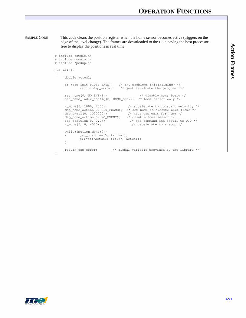
OPERATION FUNCTIONS
3-93
Action F
rames
SAMPLE CODE This code clears the position register when the home sensor becomes active (triggers on the edge of the level change). The frames are downloaded to the DSP leaving the host processor free to display the positions in real time.
# include <stdio.h># include <conio.h># include "pcdsp.h"
int main(){
double actual;
if (dsp_init(PCDSP_BASE)) /* any problems initializing? */return dsp_error; /* just terminate the program. */
set_home(0, NO_EVENT); /* disable home logic */set_home_index_config(0, HOME_ONLY); /* home sensor only */
v_move(0, 1000, 4000); /* accelerate to constant velocity */dsp_home_action(0, NEW_FRAME); /* set home to execute next frame */dsp_dwell(0, 1000000); /* have dsp wait for home */dsp_home_action(0, NO_EVENT); /* disable home sensor */set_position(0, 0.0); /* set command and actual to 0.0 */v_move(0, 0, 4000); /* decelerate to a stop */
while(!motion_done(0)){ get_position(0, &actual);
printf("Actual: %lf\r", actual);}
return dsp_error; /* global variable provided by the library */}

OPERATION FUNCTIONS
3-94
Filt
er F
ram
es
Filter Frames
dsp_set_filter downloads a frame that sets an axis’ PID filter parameters
SYNTAX int16 dsp_set_filter(int16 axis, int16 * coeffs)
PROTOTYPE IN pcdsp.h
DESCRIPTION dsp_set_filter(...) downloads a frame that sets an axis’ PID filter parameters. coeffs is a pointer to an array of integers, mapped as follows:
RETURN VALUES
SAMPLE CODE The following code increases the gain before a move, and sets the gain back to the original val-ue after the move is completed:
# include "pcdsp.h"int main(){
int16 coeff_a[COEFFICIENTS], coeff_b[COEFFICIENTS];
if (dsp_init(PCDSP_BASE)) /* any problems initializing? */return dsp_error; /* just terminate the program. */
get_filter(0, coeff_a);get_filter(0, coeff_b);coeff_a[DF_P] += 200;
dsp_set_filter(0, coeff_a);start_move(0, 100000, 8000.0, 16000.0); /* move axis 0 to 100,000 counts */dsp_set_filter(0, coeff_b);
return dsp_error; /* global variable provided by the library */}
NOTES Sometimes it’s difficult to find a set of tuning parameters that will produce accurate motion without oscillation (often due to poor mechanical systems with servo motors). Thus, it may be necessary to have two sets of tuning parameters. One set of parameters with a low gain might be used when the motor is not in motion and another set of tuning parameters with a higher gain could be used during motion. See the Installation Manual for more about finding correct filter parameters.
Table 3-17 PID Filter Parameter Mapping
#define Value Description
DF_P 0 Proportional gainDF_I 1 Integral gainDF_D 2 Derivative gain - damping termDF_ACCEL_FF 3 Acceleration feed forwardDF_VEL_FF 4 Velocity feed-forwardDF_I_LIMIT 5 Integration summing limitDF_OFFSET 6 Voltage output offsetDF_DAC_LIMIT 7 Voltage output limitDF_SHIFT 8 2^(n) divisorDF_FRICT_FF 9 Friction Feed ForwardCOEFFICIENTS 10 Number of elements
Returnsdsp_set_filter(...) Error return codes (see Error Handling on page 3-13)
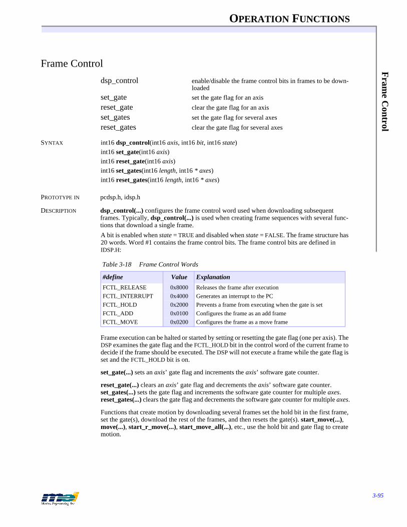
OPERATION FUNCTIONS
3-95
Fram
e Control
Frame Control
dsp_control enable/disable the frame control bits in frames to be down-loaded
set_gate set the gate flag for an axisreset_gate clear the gate flag for an axisset_gates set the gate flag for several axesreset_gates clear the gate flag for several axes
SYNTAX int16 dsp_control(int16 axis, int16 bit, int16 state)int16 set_gate(int16 axis)int16 reset_gate(int16 axis)int16 set_gates(int16 length, int16 * axes)int16 reset_gates(int16 length, int16 * axes)
PROTOTYPE IN pcdsp.h, idsp.h
DESCRIPTION dsp_control(...) configures the frame control word used when downloading subsequent frames. Typically, dsp_control(...) is used when creating frame sequences with several func-tions that download a single frame. A bit is enabled when state = TRUE and disabled when state = FALSE. The frame structure has 20 words. Word #1 contains the frame control bits. The frame control bits are defined in IDSP.H:
Frame execution can be halted or started by setting or resetting the gate flag (one per axis). The DSP examines the gate flag and the FCTL_HOLD bit in the control word of the current frame to decide if the frame should be executed. The DSP will not execute a frame while the gate flag is set and the FCTL_HOLD bit is on.
set_gate(...) sets an axis’ gate flag and increments the axis’ software gate counter.
reset_gate(...) clears an axis’ gate flag and decrements the axis’ software gate counter. set_gates(...) sets the gate flag and increments the software gate counter for multiple axes. reset_gates(...) clears the gate flag and decrements the software gate counter for multiple axes.
Functions that create motion by downloading several frames set the hold bit in the first frame, set the gate(s), download the rest of the frames, and then resets the gate(s). start_move(...), move(...), start_r_move(...), start_move_all(...), etc., use the hold bit and gate flag to create motion.
Table 3-18 Frame Control Words
#define Value Explanation
FCTL_RELEASE 0x8000 Releases the frame after executionFCTL_INTERRUPT 0x4000 Generates an interrupt to the PCFCTL_HOLD 0x2000 Prevents a frame from executing when the gate is setFCTL_ADD 0x0100 Configures the frame as an add frameFCTL_MOVE 0x0200 Configures the frame as a move frame

OPERATION FUNCTIONS
3-96
Fra
me
Con
trol
RETURN VALUES
SAMPLE CODE This code downloads a frame sequence for axis 0. The “hold” bit is turned on in the first frame to prevent execution until the complete sequence is downloaded.
# include "pcdsp.h"# include "idsp.h"
int main(){
if (dsp_init(PCDSP_BASE)) /* any problems initializing? */return dsp_error; /* just terminate the program. */
dsp_control(0, FCTL_HOLD, TRUE); /* set the hold bit */set_gate(0); /* set the axis’ gate flag */
dsp_accel(0, 1000.0, .2); /* acceleration frame */dsp_control(0, FCTL_HOLD, FALSE); /* clear the hold bit */dsp_accel(0, -1000.0, .2); /* deceleration frame */dsp_position(0, 40.0, 0.0); /* update final position */
reset_gate(0); /* ready, set, go! */
return dsp_error ; /* global variable provided by the library */}
Returnsdsp_control(...)set_gate(...)reset_gate(...)set_gates(...)reset_gates(...)
Error return codes (see Error Handling on page 3-13)

OPERATION FUNCTIONS
3-97
Tim
e
Time
get_dsp_time returns the DSP’s sample timer valueget_frame_time returns an axis’ frame sample timer value
SYNTAX unsigned16 get_dsp_time(void)unsigned long get_frame_time(int16 axis)
PROTOTYPE IN pcdsp.h
DESCRIPTION get_dsp_time(...) returns the integer value of the DSP’s sample timer. get_frame_time(...) re-turns an unsigned long value of an axis’s frame sample timer. Whenever a frame is executed by the DSP, the frame sample timer is reset to zero. The units for these values are in terms of samples. The default sample rate is 1250 samples per second.
RETURN VALUE integer or long value representing the number of samples
SEE ALSO dsp_sample_rate(...), set_sample_rate(...)
SAMPLE CODE This code prints the sample timer value before and after a simple move.
# include <stdio.h># include "pcdsp.h"
int main(){
if (dsp_init(PCDSP_BASE)) /* any problems initializing? */return dsp_error; /* just terminate the program. */
if (dsp_reset()) /* resets the controller and sample clock */return dsp_error;
printf("\nSample Clock: %d\n", get_dsp_time());r_move(0, 100., 1000., 20000.);printf("\nSample Clock: %d\n", get_dsp_time());
return dsp_error ; /* global variable provided by the library */}
Returnsget_dsp_time(...)get_frame_time(...)
Values

OPERATION FUNCTIONS
3-98
Dir
ect M
emor
y A
cces
s
Direct Memory Access
dsp_read_dm access the DSP's data memorydsp_write_dm modify the DSP's data memory
SYNTAX int16 dsp_read_dm(unsigned16 addr)int16 dsp_write_dm(unsigned16 addr, int16 dm)
PROTOTYPE IN pcdsp.h
DESCRIPTION The functions dsp_read_dm(...) and dsp_write_dm(...) allow direct access to the DSP's exter-nal data memory. Most fundamental communication with the controller is via messages passed through this data area.These functions provide a low-level access to the DSP controller and are typically not needed for normal user programs. These functions can be used to read the peripherals directly:
Table 3-19 Encoder DMA Addresses
Encoder Input Address Analog Input Address
Axis 0 0x0014 Channel 0 0x0020Axis 1 0x0015 Channel 1 0x0021Axis 2 0x0016 Channel 2 0x0022Axis 3 0x0017 Channel 3 0x0023Axis 4 0x0018 Channel 4 0x0024Axis 5 0x0019 Channel 5 0x0025Axis 6 0x001A Channel 6 0x0026Axis 7 0x001B Channel 7 0x0027
Table 3-20 Dedicated I/O DMA Addresses
Dedicated I/O (axes 0 - 3) Address Dedicated I/O
(axes 4 - 7) Address
82C55-0 Port 6 0x0030 82C55-1 Port 3 0x003882C55-0 Port 7 0x0031 82C55-1 Port 4 0x003982C55-0 Port 8 0x0032 82C55-1 Port 5 0x003A82C55-0 Control 0x0033 82C55-1 Control 0x003B
Table 3-21 User I/O DMA Addresses
User I/O Address
82C55-2 Port 0 0x004082C55-2 Port 1 0x004182C55-2 Port 2 0x004282C55-2 Control 0x0043

OPERATION FUNCTIONS
3-99
Direct M
emory A
ccess
RETURN VALUES
SAMPLE CODE This code reads the 16-bit value from the encoder circuitry on axis 0 and axis 1.
# include "pcdsp.h"
int main(){
int16 pos_0, pos_1;
if (dsp_init(PCDSP_BASE)) /* any problems initializing? */return dsp_error; /* just terminate the program. */
pos_0 = dsp_read_dm(0x0014);pos_1 = dsp_read_dm(0x0015);printf("\nEncoder0: %d Encoder1: %d\n", pos_0, pos_1);
return dsp_error ; /* global variable provided by the library */}
Table 3-22 Internal Logic DMA Addresses
Internal Logic Address Internal Logic Address
82C55-3 Port A 0x0048 82C55-4 Port A 0x005082C55-3 Port B 0x0049 82C55-4 Port B 0x005182C55-3 Port C 0x004A 82C55-4 Port C 0x005282C55-3 Control 0x004B 82C55-4 Control 0x0053
Returnsdsp_read_dm(...)dsp_write_dm(...)
Error return codes (see Error Handling on page 3-13)

OPERATION FUNCTIONS
3-100
Dir
ect M
emor
y A
cces
s

ABOUT THE DSP CONTROLLER
A-1
APPENDIX A ABOUT THE DSP CONTROLLER
Hardware Architecture A-2
Hardware + Firmware + Software A-3
Internal Boot Sequence A-4
Firmware Execution A-4
Step Motor Control via VFCs A-6
Motion Concepts A-8
What is a Frame? A-8
Communication via 3 Words in I/O Space A-8
Function Execution Time A-8
Coordinated Motion A-9
How to Program Coordinated Motion A-10
I/O with Coordinated Motion A-11

ABOUT THE DSP CONTROLLER
A-2
Har
dwar
e A
rchi
tect
ure
Hardware ArchitectureThe DSP Series controller uses a unique architecture to provide advanced capabilities without excessive complexity. Instead of sending ASCII strings to the controller, the MEI software communicates directly with the controller. The DSP Series controller is mapped into the I/O space of the host CPU and allows direct binary communication across the DSP’s data bus.
A complete function library and source code is provided with the DSP Series controller. The library functions manipulate and conceal the internal details of the controller, enabling you to concentrate on the application.
Open architecture takes advantage of the power, memory and abundance of peripherals avail-able with modern computers. It provides an excellent development platform with familiar pro-gramming tools and minimal operating system overhead. Users are not restricted by commands stored in EPROM. Applications are not hindered by slow internal ASCII communications. Mo-tion and I/O control can be buffered on-board or executed immediately.
The controller utilizes the Analog Devices 40 MHz ADSP-2105 device for on-board computing power. The DSP handles all servo-loop calculations, command position trajectory calculations, frame buffer execution, response to programmable software limits, hardware limits, and many other features.
On a hardware level, the controller is a small microcomputer unto itself. It has its own address and data bus which the DSP, its data memory, and peripherals use for communication. The host CPU and the DSP have direct access to the data bus enabling fast communication. The host CPU and the DSP do not have direct communication; instead messages are passed through the DSP's external data memory via the data bus. It's like a chalkboard, where they communicate by reading or writing messages, instead of directly modifying DSP registers.
However, the DSP does not require the constant attention of the CPU. The only time the CPU needs to perform reads/writes to the data bus is when your application requests information or commands motion. Commanded motion can be executed immediately or stored in the DSP's memory buffer for later execution.

ABOUT THE DSP CONTROLLER
A-3
Hardw
are Architecture
Hardw
are + F
irmw
are + Softw
are
Figure A-1 DSP Controller Block Diagram
Hardware + Firmware + SoftwareThe hardware consists of a DSP, memory (volatile and non-volatile), 16-bit A/D converter(s), +/-10 volt op-amp output(s), voltage-to frequency-converter(s) (VFC), 8255 chips for user and dedicated I/O, assorted programmable logic and bus interface components. Some versions also have an 8-channel 12-bit A/D converter and an 8254 counter/timer.
The DSPpro Series, which consists of the DSPpro-Serial, DSPpro-PC, and DSPpro-VME, combines an Intel 386EX microprocessor and 387 math coprocessor along with the Analog De-vices DSP. High-level decisions and communications with the host processor occur on the 386EX, while the DSP is responsible for numerically intensive calculations. With embedded DOS running on the 386EX, standard programs can execute on the DSPpro, completely inde-pendent of the host processor.
The firmware is written in Analog Devices assembly code and is stored in nonvolatile memory. The firmware contains the code necessary to operate the hardware as a motion controller. With-out the firmware, the DSP Series controller would simply be a generic I/O, A/D, D/A board. The firmware handles the real-time operation of the motion controller. The controller boot con-figurations are also stored in the firmware. Firmware can be uploaded to the host CPU and stored in a disk file or downloaded to the controller from a disk file.
The software resides in the host CPU. It contains all of the code necessary to communicate with the controller, configure the controller’s hardware, configure its responses, command motion,
Serial Data
Up to 8
Encoder Inputs
Analog Inputs
Dedicated I/O(6 lines/axis)
User I/O(up to 44 lines)
Bus Interface
DSP40 MHZ
DSPMEMORY
Servo Outputs(16-BIT D/A)
Step/Direction Outputs
Up to 8
Host CPU
The design of the controller allows the host CPU to directly access the DSP’s data bus.
DSP Data Bus
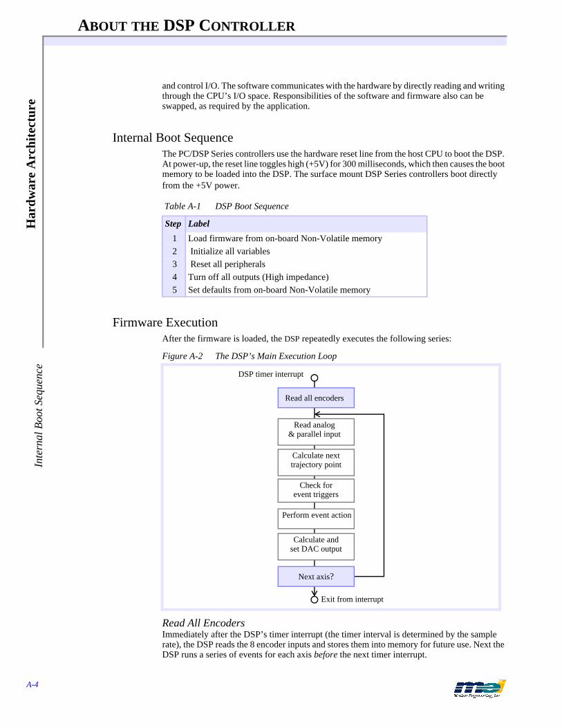
ABOUT THE DSP CONTROLLER
A-4
Har
dwar
e A
rchi
tect
ure
Inte
rnal
Boo
t Seq
uenc
e
and control I/O. The software communicates with the hardware by directly reading and writing through the CPU’s I/O space. Responsibilities of the software and firmware also can be swapped, as required by the application.
Internal Boot SequenceThe PC/DSP Series controllers use the hardware reset line from the host CPU to boot the DSP. At power-up, the reset line toggles high (+5V) for 300 milliseconds, which then causes the boot memory to be loaded into the DSP. The surface mount DSP Series controllers boot directly from the +5V power.
Firmware ExecutionAfter the firmware is loaded, the DSP repeatedly executes the following series:
Figure A-2 The DSP’s Main Execution Loop
Read All EncodersImmediately after the DSP’s timer interrupt (the timer interval is determined by the sample rate), the DSP reads the 8 encoder inputs and stores them into memory for future use. Next the DSP runs a series of events for each axis before the next timer interrupt.
Table A-1 DSP Boot Sequence
Step Label
1 Load firmware from on-board Non-Volatile memory2 Initialize all variables3 Reset all peripherals4 Turn off all outputs (High impedance)5 Set defaults from on-board Non-Volatile memory
Read all encoders
Read analog & parallel input
Calculate next trajectory point
Check for event triggers
DSP timer interrupt
Perform event action
Calculate and set DAC output
Exit from interrupt
Next axis?

ABOUT THE DSP CONTROLLER
A-5
Hardw
are Architecture
Firm
ware E
xecution
Read Analog and Parallel InputIf an axis is configured to read an analog input, the DSP writes a control word to the A/D, waits for the conversion, reads the 12-bit digital value, and stores it in memory. If an axis is config-ured to read the parallel input, the DSP reads the 32 user I/O bits and stores the values in mem-ory.
Calculate Next Trajectory PointThe DSP calculates an axis’ command position trajectory. It maintains a command jerk, com-mand acceleration, command velocity, and command position.
WhereTn is the time at sample nAn is the command acceleration at sample nVn is the command velocity at sample nXn is the command position at sample n
andFdSpd is the feed speedJ is the command jerk
The command velocity is the rate of change of the command position, the command accelera-tion is the rate of change of the command velocity, and the command jerk is the rate of change of the command acceleration.
Check for Event TriggersThe DSP checks an axis’ positive limit input, negative limit input, home input, amp fault input, and software position limits. Also, the DSP checks the axis for time limits, position triggers, and I/O triggers to determine if a new frame is to be executed.
Perform Event ActionsIf an event trigger exists for an axis, the DSP performs the associated event. The 4 possible types of events are: Abort Event (highest priority), E-Stop Event, Stop Event, or New Frame Event (lowest priority).
Calculate and Set DAC OutputThe DSP calculates an axis’ output (analog voltage or pulse rate) based on a PID servo-control algorithm. The input to the PID algorithm is the current position error. The current position er-ror equals the difference between the command position and the actual position. The actual po-sition is controlled by the feedback device, while the command position is controlled by the trajectory calculator. The PID algorithm is based on a formula.
Table A-2 Trajectory Calculations at Sample n
Quantity Calculation
Time Tn = Tn-1 + FdSpd
Command acceleration An = An-1 + FdSpd * J
Command velocity Vn = Vn-1 + FdSpd * An
Command position Xn = Xn-1 + FdSpd * Vn
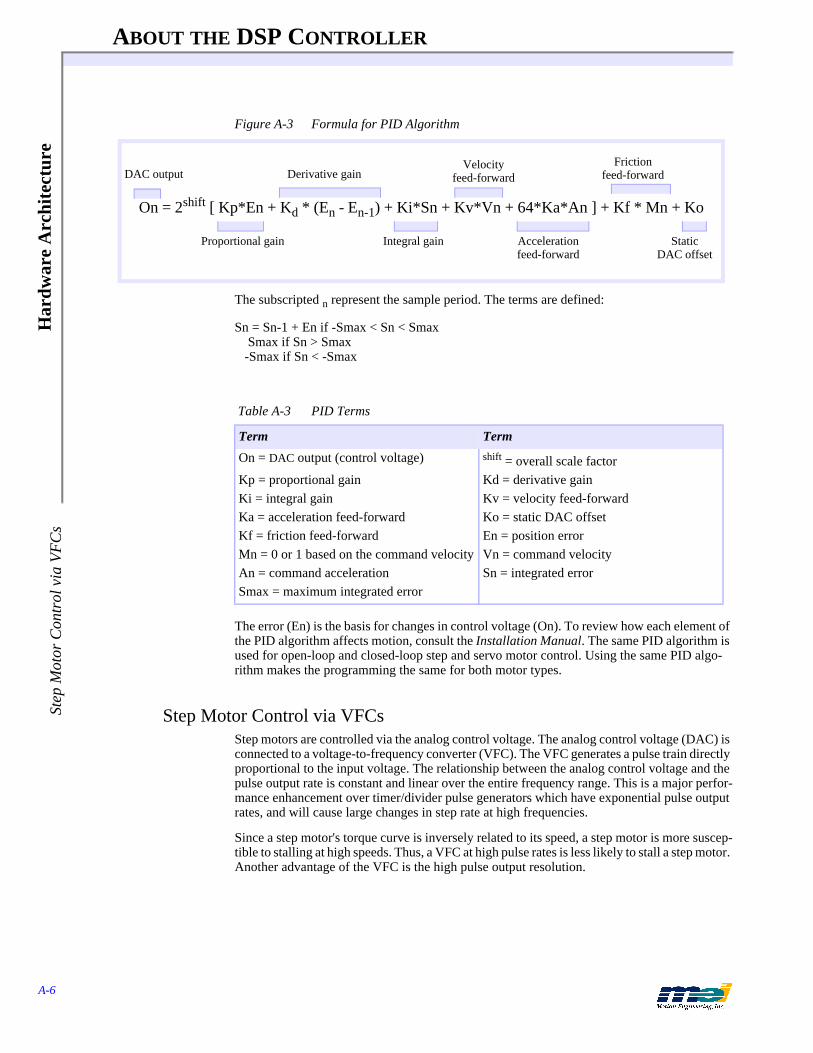
ABOUT THE DSP CONTROLLER
A-6
Har
dwar
e A
rchi
tect
ure
Step
Mot
or C
ontr
ol v
ia V
FC
s
Figure A-3 Formula for PID Algorithm
The subscripted n represent the sample period. The terms are defined:
Sn = Sn-1 + En if -Smax < Sn < Smax Smax if Sn > Smax -Smax if Sn < -Smax
The error (En) is the basis for changes in control voltage (On). To review how each element of the PID algorithm affects motion, consult the Installation Manual. The same PID algorithm is used for open-loop and closed-loop step and servo motor control. Using the same PID algo-rithm makes the programming the same for both motor types.
Step Motor Control via VFCsStep motors are controlled via the analog control voltage. The analog control voltage (DAC) is connected to a voltage-to-frequency converter (VFC). The VFC generates a pulse train directly proportional to the input voltage. The relationship between the analog control voltage and the pulse output rate is constant and linear over the entire frequency range. This is a major perfor-mance enhancement over timer/divider pulse generators which have exponential pulse output rates, and will cause large changes in step rate at high frequencies.
Since a step motor's torque curve is inversely related to its speed, a step motor is more suscep-tible to stalling at high speeds. Thus, a VFC at high pulse rates is less likely to stall a step motor. Another advantage of the VFC is the high pulse output resolution.
Table A-3 PID Terms
Term Term
On = DAC output (control voltage) shift = overall scale factorKp = proportional gain Kd = derivative gainKi = integral gain Kv = velocity feed-forwardKa = acceleration feed-forward Ko = static DAC offsetKf = friction feed-forward En = position errorMn = 0 or 1 based on the command velocity Vn = command velocityAn = command acceleration Sn = integrated errorSmax = maximum integrated error
On = 2shift [ Kp*En + Kd * (En - En-1) + Ki*Sn + Kv*Vn + 64*Ka*An ] + Kf * Mn + Ko
Proportional gain
Derivative gain
Integral gain
Velocity feed-forward
Acceleration feed-forward
Friction feed-forward
Static DAC offset
DAC output

ABOUT THE DSP CONTROLLER
A-7
Hardw
are Architecture
Step Motor C
ontrol via VF
Cs
The step pulse output supports the following speed ranges:
* To use the superfast step output speed, you must have version 2.5.05 software, 1.33/2.33 PROMS, and the following hardware board revisions (or higher):
The voltage level at which steps are produced by the VFCs is determined by the internal DAC offset set by the CONFIG.EXE program. This offset is usually required so that the DAC’s out-put zero agrees with the VFC’s input zero. If the analog zero volt output is above the VFC zero input, the VFC will begin outputting steps.
The firmware guarantees the VFC will not output steps when the command velocity is zero and the position error is zero. If the offset is set too high, the firmware will automatically shut down the step pulse output at the end of a move. If the offset was set too low, a small delay will occur between the time the command position changes and the step motor actually starts moving. The delay would be minimal, rarely exceeding 2 sample periods and would be based on the accel-eration and velocity figures.
One great design advantage is that the same programming is used to control either step or servo motors. If no motors are connected to the DSP Series controller, you can simulate motors by configuring the axes as open-loop steppers. Refer to the DSP Series Installation Guide.
Table A-4 Step Pulse Output Speed Ranges
Controller Slow(kHz)
Medium(kHz)
Fast(kHz)
Superfast *(kHz)
PC/DSP 0 - 125 0 - 500 0 - 2.0 MHz N/APCX/DSP 0 - 20 0 - 80 0 - 325 0 - 550 STD/DSP 0 - 20 0 - 80 0 - 325 0 - 550 104/DSP 0 - 20 0 - 80 0 - 325 0 - 550 LC/DSP 0 - 20 0 - 80 0 - 325 0 - 550 V6U/DSP 0 - 20 0 - 80 0 - 325 0 - 550 104X/DSP 0 - 20 0 - 80 0 - 325 0 - 550 DSPpro-Serial 0 - 20 0 - 80 0 - 325 0 - 550 DSPpro-VME 0 - 20 0 - 80 0 - 325 0 - 550 CPCI/DSP 0 - 20 0 - 80 0 - 325 0 - 550 PCI.DSP 0 - 20 0 - 80 0 - 325 0 - 550
Table A-5 Minimum Hardware Revision Levels Required for Faster Step Output Speed
Controller Revision
PCX/DSP 3STD/DSP 8104/DSP 6104X/DSP 2LC/DSP 8CPCI/DSP 1PCI/DSP 1VME/DSP 3
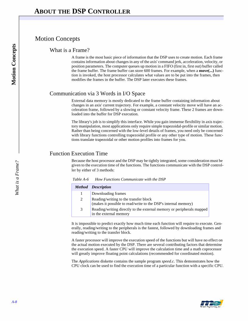
ABOUT THE DSP CONTROLLER
A-8
Mot
ion
Con
cept
sW
hat i
s a
Fra
me?
Motion Concepts
What is a Frame?A frame is the most basic piece of information that the DSP uses to create motion. Each frame contains information about changes in any of the axis' command jerk, acceleration, velocity, or position parameters. The computer queues up motion in a FIFO (first in, first out) buffer called the frame buffer. The frame buffer can store 600 frames. For example, when a move(...) func-tion is invoked, the host processor calculates what values are to be put into the frames, then modifies the frames in the buffer. The DSP later executes these frames.
Communication via 3 Words in I/O SpaceExternal data memory is mostly dedicated to the frame buffer containing information about changes in an axis' current trajectory. For example, a constant velocity move will have an ac-celeration frame, followed by a slowing or constant velocity frame. These 2 frames are down-loaded into the buffer for DSP execution.
The library's job is to simplify this interface. While you gain immense flexibility in axis trajec-tory manipulation, most applications only require simple trapezoidal-profile or similar motion. Rather than being concerned with the low-level details of frames, you need only be concerned with library functions controlling trapezoidal profile or any other type of motion. These func-tions translate trapezoidal or other motion profiles into frames for you.
Function Execution TimeBecause the host processor and the DSP may be tightly integrated, some consideration must be given to the execution time of the functions. The functions communicate with the DSP control-ler by either of 3 methods:
It is impossible to predict exactly how much time each function will require to execute. Gen-erally, reading/writing to the peripherals is the fastest, followed by downloading frames and reading/writing to the transfer block.
A faster processor will improve the execution speed of the functions but will have no effect on the actual motion executed by the DSP. There are several contributing factors that determine the execution speed. A faster CPU will improve the calculation time and a math coprocessor will greatly improve floating point calculations (recommended for coordinated motion).
The Applications diskette contains the sample program speed.c. This demonstrates how the CPU clock can be used to find the execution time of a particular function with a specific CPU.
Table A-6 How Functions Communicate with the DSP
Method Description
1 Downloading frames2 Reading/writing to the transfer block
(makes it possible to read/write to the DSP's internal memory)3 Reading/writing directly to the external memory or peripherals mapped
in the external memory
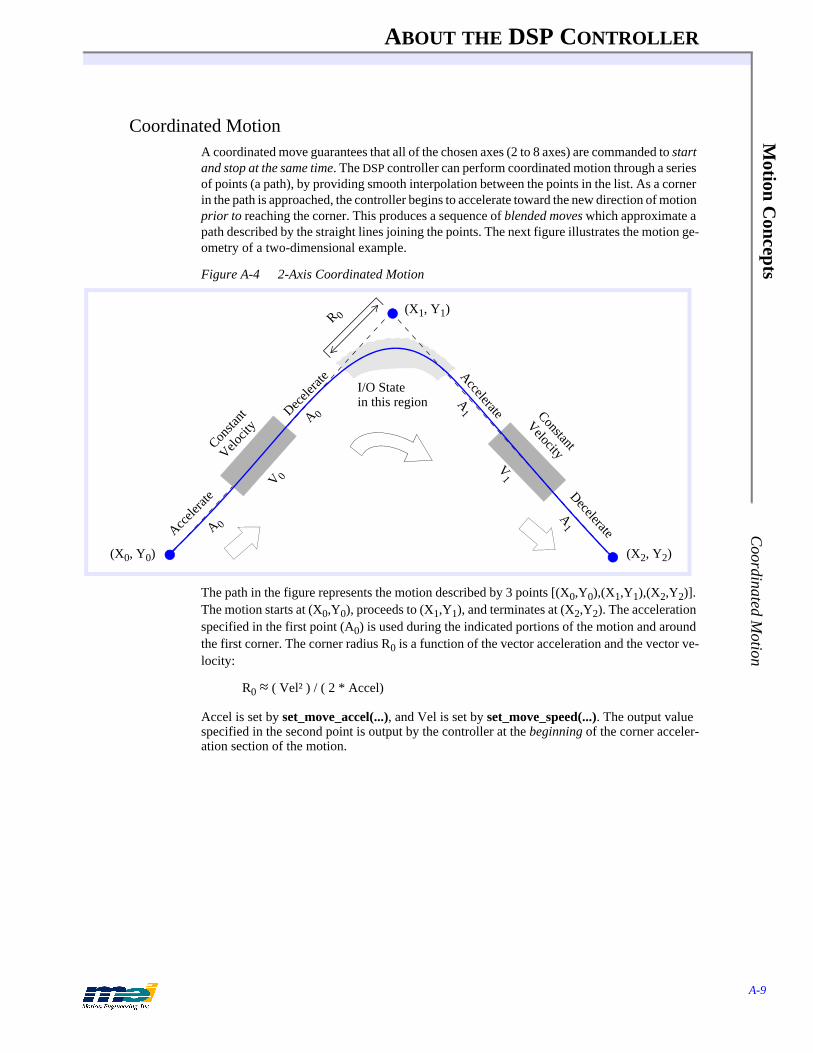
ABOUT THE DSP CONTROLLER
A-9
Motion C
oncepts C
oordinated Motion
Coordinated MotionA coordinated move guarantees that all of the chosen axes (2 to 8 axes) are commanded to start and stop at the same time. The DSP controller can perform coordinated motion through a series of points (a path), by providing smooth interpolation between the points in the list. As a corner in the path is approached, the controller begins to accelerate toward the new direction of motion prior to reaching the corner. This produces a sequence of blended moves which approximate a path described by the straight lines joining the points. The next figure illustrates the motion ge-ometry of a two-dimensional example.
Figure A-4 2-Axis Coordinated Motion
The path in the figure represents the motion described by 3 points [(X0,Y0),(X1,Y1),(X2,Y2)]. The motion starts at (X0,Y0), proceeds to (X1,Y1), and terminates at (X2,Y2). The acceleration specified in the first point (A0) is used during the indicated portions of the motion and around the first corner. The corner radius R0 is a function of the vector acceleration and the vector ve-locity:
R0 ≈ ( Vel² ) / ( 2 * Accel)
Accel is set by set_move_accel(...), and Vel is set by set_move_speed(...). The output value specified in the second point is output by the controller at the beginning of the corner acceler-ation section of the motion.
Consta
nt
Velocit
y
(X0, Y0) (X2, Y2)
(X1, Y1)R 0
V1V 0
A1
A 0
A 0
Accele
rate
Decele
rate Accelerate
Decelerate
Constant
VelocityA
1
I/O State in this region
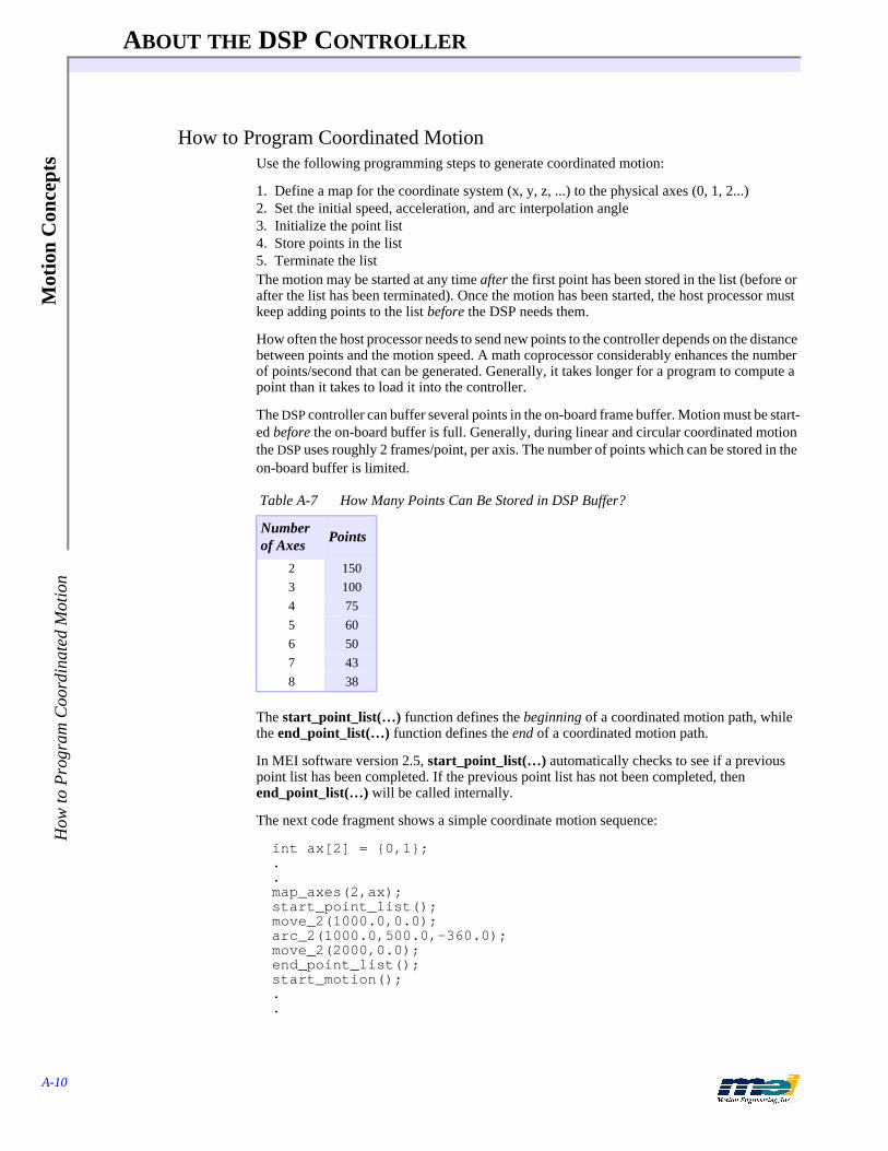
ABOUT THE DSP CONTROLLER
A-10
Mot
ion
Con
cept
sH
ow to
Pro
gram
Coo
rdin
ated
Mot
ion
How to Program Coordinated MotionUse the following programming steps to generate coordinated motion:
1. Define a map for the coordinate system (x, y, z, ...) to the physical axes (0, 1, 2...)2. Set the initial speed, acceleration, and arc interpolation angle3. Initialize the point list4. Store points in the list5. Terminate the listThe motion may be started at any time after the first point has been stored in the list (before or after the list has been terminated). Once the motion has been started, the host processor must keep adding points to the list before the DSP needs them.
How often the host processor needs to send new points to the controller depends on the distance between points and the motion speed. A math coprocessor considerably enhances the number of points/second that can be generated. Generally, it takes longer for a program to compute a point than it takes to load it into the controller.
The DSP controller can buffer several points in the on-board frame buffer. Motion must be start-ed before the on-board buffer is full. Generally, during linear and circular coordinated motion the DSP uses roughly 2 frames/point, per axis. The number of points which can be stored in the on-board buffer is limited.
The start_point_list(…) function defines the beginning of a coordinated motion path, while the end_point_list(…) function defines the end of a coordinated motion path.
In MEI software version 2.5, start_point_list(…) automatically checks to see if a previous point list has been completed. If the previous point list has not been completed, then end_point_list(…) will be called internally.
The next code fragment shows a simple coordinate motion sequence:
int ax[2] = {0,1};..map_axes(2,ax);start_point_list();move_2(1000.0,0.0);arc_2(1000.0,500.0,-360.0);move_2(2000,0.0);end_point_list();start_motion();..
Table A-7 How Many Points Can Be Stored in DSP Buffer?
Number of Axes Points
2 1503 1004 755 606 507 438 38
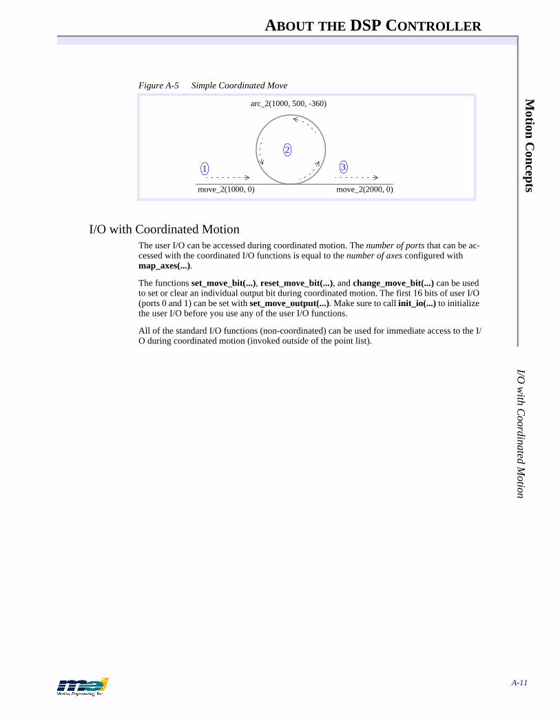
ABOUT THE DSP CONTROLLER
A-11
Motion C
oncepts I/O
with C
oordinated Motion
Figure A-5 Simple Coordinated Move
I/O with Coordinated MotionThe user I/O can be accessed during coordinated motion. The number of ports that can be ac-cessed with the coordinated I/O functions is equal to the number of axes configured with map_axes(...).
The functions set_move_bit(...), reset_move_bit(...), and change_move_bit(...) can be used to set or clear an individual output bit during coordinated motion. The first 16 bits of user I/O (ports 0 and 1) can be set with set_move_output(...). Make sure to call init_io(...) to initialize the user I/O before you use any of the user I/O functions.
All of the standard I/O functions (non-coordinated) can be used for immediate access to the I/O during coordinated motion (invoked outside of the point list).
1
2
3
move_2(1000, 0)
arc_2(1000, 500, -360)
move_2(2000, 0)
ABOUT THE DSP CONTROLLER
A-12
Mot
ion
Con
cept
sI/
O w
ith C
oord
inat
ed M
otio
n

B-1
APPENDIX B ABOUT SERCOS
The SERCOS (Serial Real-Time Communication System) protocol was designed specifically for the motion control industry. The protocol uses a ring topology which allows communication to occur at specific assigned times within a predetermined cycle. Thus, SERCOS is deterministic allowing the Master (control unit) to synchronize command and feedback values to and from all of the Slaves (drives). Major topics in this chapter include
Brief Intro B-2About the MEI SERCOS Controller B-2Supported Drives/Modules B-2
MEI Software B-3Initialization Structures B-3Drive Manufacturers B-3Drive Modes B-4Initialization Status B-4
MEI Developer Topics B-6Service Channel error messages B-6
SERCOS Overview B-7Telegrams B-11Master Synchronization Telegram (MST) B-14Master Data Telegram (MDT) B-15Amplifier Telegram (AT) B-17SERCOS Data Types B-19SERCOS Procedures B-24
SERCOS Communications B-25Synchronization B-25SERCOS Ring Timing B-25SERCOS Initialization B-27
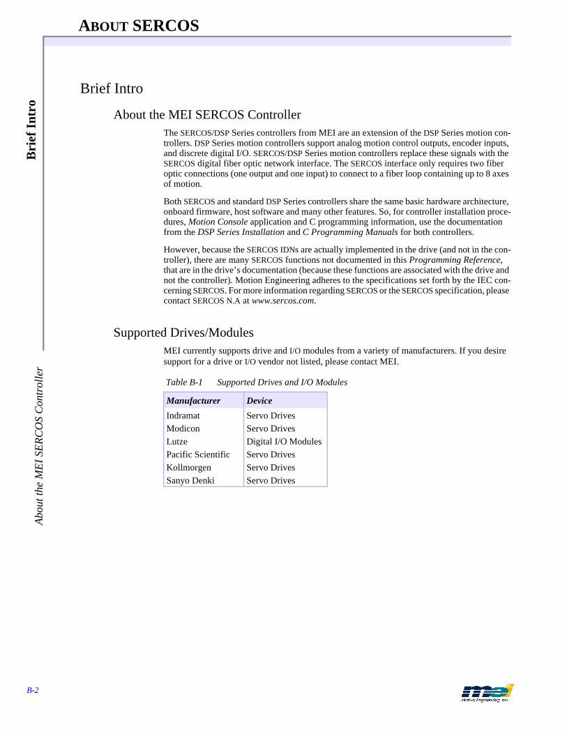
ABOUT SERCOS
B-2
Bri
ef I
ntro
Abo
ut th
e M
EI S
ER
CO
S C
ontr
olle
r
Brief Intro
About the MEI SERCOS ControllerThe SERCOS/DSP Series controllers from MEI are an extension of the DSP Series motion con-trollers. DSP Series motion controllers support analog motion control outputs, encoder inputs, and discrete digital I/O. SERCOS/DSP Series motion controllers replace these signals with the SERCOS digital fiber optic network interface. The SERCOS interface only requires two fiber optic connections (one output and one input) to connect to a fiber loop containing up to 8 axes of motion.
Both SERCOS and standard DSP Series controllers share the same basic hardware architecture, onboard firmware, host software and many other features. So, for controller installation proce-dures, Motion Console application and C programming information, use the documentation from the DSP Series Installation and C Programming Manuals for both controllers.
However, because the SERCOS IDNs are actually implemented in the drive (and not in the con-troller), there are many SERCOS functions not documented in this Programming Reference, that are in the drive’s documentation (because these functions are associated with the drive and not the controller). Motion Engineering adheres to the specifications set forth by the IEC con-cerning SERCOS. For more information regarding SERCOS or the SERCOS specification, please contact SERCOS N.A at www.sercos.com.
Supported Drives/ModulesMEI currently supports drive and I/O modules from a variety of manufacturers. If you desire support for a drive or I/O vendor not listed, please contact MEI.
Table B-1 Supported Drives and I/O Modules
Manufacturer Device
Indramat Servo DrivesModicon Servo DrivesLutze Digital I/O ModulesPacific Scientific Servo DrivesKollmorgen Servo DrivesSanyo Denki Servo Drives
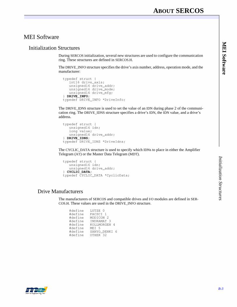
ABOUT SERCOS
B-3
ME
I Software
Initialization Structures
MEI Software
Initialization StructuresDuring SERCOS initialization, several new structures are used to configure the communication ring. These structures are defined in SERCOS.H.
The DRIVE_INFO structure specifies the drive’s axis number, address, operation mode, and the manufacturer:
typedef struct {int16 drive_axis;unsigned16 drive_addr;unsigned16 drive_mode;unsigned16 drive_mfg;
} DRIVE_INFO;typedef DRIVE_INFO *DriveInfo;
The DRIVE_IDNS structure is used to set the value of an IDN during phase 2 of the communi-cation ring. The DRIVE_IDNS structure specifies a drive’s IDN, the IDN value, and a drive’s address.
typedef struct {unsigned16 idn;long value;unsigned16 drive_addr;
} DRIVE_IDNS;typedef DRIVE_IDNS *DriveIdns;
The CYCLIC_DATA structure is used to specify which IDNs to place in either the Amplifier Telegram (AT) or the Master Data Telegram (MDT).
typedef struct {unsigned16 idn;unsigned16 drive_addr;
} CYCLIC_DATA;typedef CYCLIC_DATA *CyclicData;
Drive ManufacturersThe manufacturers of SERCOS and compatible drives and I/O modules are defined in SER-COS.H. These values are used in the DRIVE_INFO structure.
#define LUTZE 0#define PACSCI 1#define MODICON 2#define INDRAMAT 3#define KOLLMORGEN 4#define MEI 5#define SANYO_DENKI 6#define OTHER 32

ABOUT SERCOS
B-4
ME
I So
ftw
are
Dri
ve M
odes
Drive ModesNote: Any drive mode with _STD appended will not support user-specified cyclic data. serc_reset(...) will ignore user specified cyclic data configurations for a drive mode appended with _STD. Several drive modes and drive mode variations are supported:
Initialization StatusDuring initialization with serc_reset(…), information is written to several status variables and structures. These variables and structures can be very useful in debugging initialization prob-lems.
During initialization, several status messages are copied to driveMsgs from IDN 95.
typedef struct{char msgstr[MAX_ERROR_LEN];
} MsgStr;extern MsgStr driveMsgs[PCDSP_MAX_AXES][MSGS_PER_AXIS];
If serc_reset(...) fails to initialize the communication ring, it will return a non-zero error code. This error code, the driveMsgs, and the visual display on the drive can be used to trouble-shoot initialization problems. Please see the sample SERCOS Initialization programs on the Ap-plications diskette and SERCOS Initialization on B-27.
Here are some additional variables and arrays that contain status information regarding SER-COS initialization:
extern int16 assignedDrive[PCDSP_MAX_AXES];extern int16 driveCount; /* number of drives found during
serc_reset() */extern int16 logCount[PCDSP_MAX_AXES]; /* number of drive messages
for each axis */
Table B-2 SERCOS Drive Modes Supported
defines Value Description
TORQMODE 1 Torque mode (telegram type 7)VELMODE 2 Velocity mode (telegram type 7)POSMODE 3 Position mode (telegram type 7)VELOCITY_STD 5 Standard telegram type 3
(no user-specified cyclic data)POSITION_STD 6 Standard telegram type 4
(no user-specified cyclic data)POS_VEL_STD 7 Standard telegram type 5
(no user-specified cyclic data)EXT_VELMODE 9 Indramat drive, Velocity mode, 2nd position encoder
(telegram type 7)DUAL_LOOP_VELMODE 10 Velocity control, dual encoder feedback
(telegram type 7)ANALOG_VELMODE 11 Velocity control, analog feedback (telegram type 7)ANALOG_TORQUEMODE 12 Torque control, analog feedback (telegram type 7)USERMAP 13 User-specified cyclic data (telegram type 7)
ABOUT SERCOS
B-5
ME
I Software
Initialization Status
/* The following data structures are filled out if serc_reset() fails during the transition between phase 2 and phase 3. */
extern int16 phase2_idncount[PCDSP_MAX_AXES]; /* number of IDNs not set correctly */
extern unsigned16 phase2_idnlist[PCDSP_MAX_AXES][MAX_IDNLIST_LEN];
/* The following data structures are filled out if serc_reset() fails during the transition between phase 3 and phase 4.*/
extern int16 phase3_idncount[PCDSP_MAX_AXES]; /* number of IDNs not set correctly */
extern unsigned16 phase3_idnlist[PCDSP_MAX_AXES][MAX_IDNLIST_LEN];
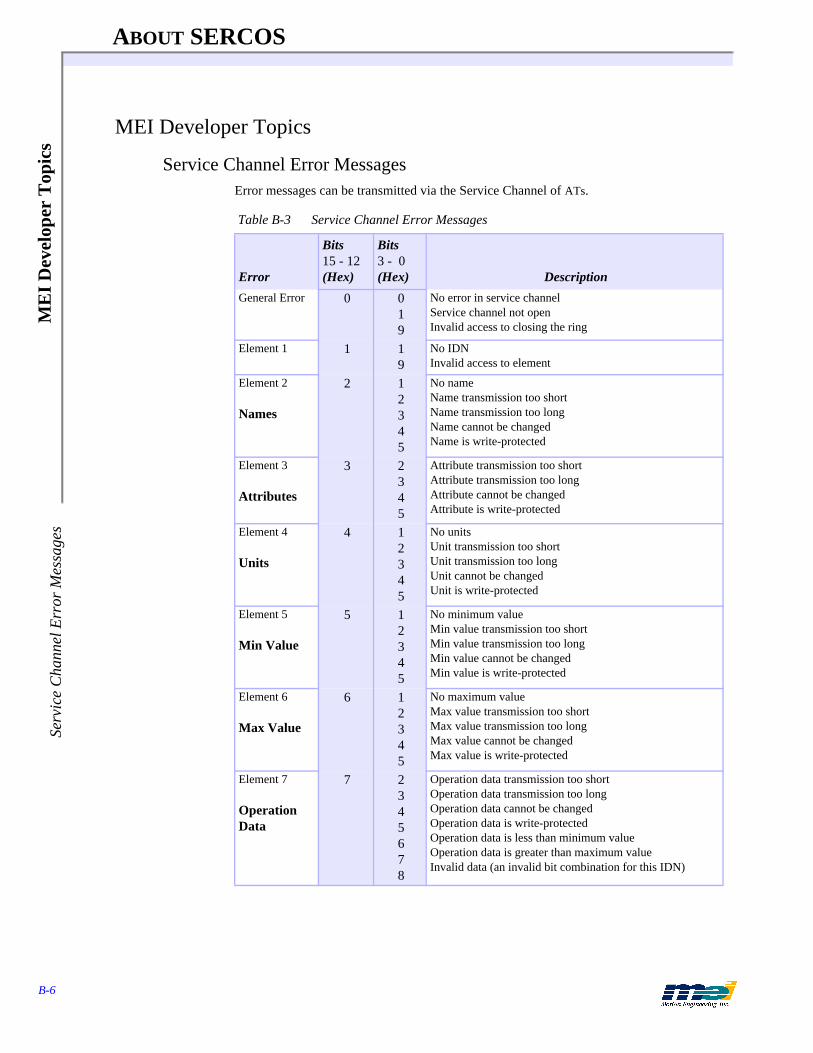
ABOUT SERCOS
B-6
ME
I D
evel
oper
Top
ics
Serv
ice
Cha
nnel
Err
or M
essa
ges
MEI Developer Topics
Service Channel Error MessagesError messages can be transmitted via the Service Channel of ATs.
Table B-3 Service Channel Error Messages
Error
Bits15 - 12(Hex)
Bits3 - 0(Hex) Description
General Error 0 019
No error in service channelService channel not openInvalid access to closing the ring
Element 1 1 19
No IDNInvalid access to element
Element 2
Names
2 12345
No nameName transmission too shortName transmission too longName cannot be changedName is write-protected
Element 3
Attributes
3 2345
Attribute transmission too short Attribute transmission too long Attribute cannot be changedAttribute is write-protected
Element 4
Units
4 12345
No unitsUnit transmission too short Unit transmission too long Unit cannot be changedUnit is write-protected
Element 5
Min Value
5 12345
No minimum valueMin value transmission too short Min value transmission too long Min value cannot be changedMin value is write-protected
Element 6
Max Value
6 12345
No maximum valueMax value transmission too short Max value transmission too long Max value cannot be changedMax value is write-protected
Element 7
Operation Data
7 2345678
Operation data transmission too short Operation data transmission too long Operation data cannot be changedOperation data is write-protectedOperation data is less than minimum valueOperation data is greater than maximum valueInvalid data (an invalid bit combination for this IDN)
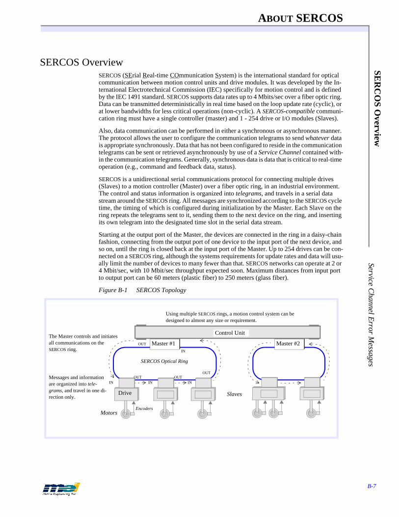
ABOUT SERCOS
B-7
SER
CO
S Overview
Service Channel E
rror Messages
SERCOS OverviewSERCOS (SErial Real-time COmmunication System) is the international standard for optical communication between motion control units and drive modules. It was developed by the In-ternational Electrotechnical Commission (IEC) specifically for motion control and is defined by the IEC 1491 standard. SERCOS supports data rates up to 4 Mbits/sec over a fiber optic ring. Data can be transmitted deterministically in real time based on the loop update rate (cyclic), or at lower bandwidths for less critical operations (non-cyclic). A SERCOS-compatible communi-cation ring must have a single controller (master) and 1 - 254 drive or I/O modules (Slaves).
Also, data communication can be performed in either a synchronous or asynchronous manner. The protocol allows the user to configure the communication telegrams to send whatever data is appropriate synchronously. Data that has not been configured to reside in the communication telegrams can be sent or retrieved asynchronously by use of a Service Channel contained with-in the communication telegrams. Generally, synchronous data is data that is critical to real-time operation (e.g., command and feedback data, status).
SERCOS is a unidirectional serial communications protocol for connecting multiple drives (Slaves) to a motion controller (Master) over a fiber optic ring, in an industrial environment. The control and status information is organized into telegrams, and travels in a serial data stream around the SERCOS ring. All messages are synchronized according to the SERCOS cycle time, the timing of which is configured during initialization by the Master. Each Slave on the ring repeats the telegrams sent to it, sending them to the next device on the ring, and inserting its own telegram into the designated time slot in the serial data stream.
Starting at the output port of the Master, the devices are connected in the ring in a daisy-chain fashion, connecting from the output port of one device to the input port of the next device, and so on, until the ring is closed back at the input port of the Master. Up to 254 drives can be con-nected on a SERCOS ring, although the systems requirements for update rates and data will usu-ally limit the number of devices to many fewer than that. SERCOS networks can operate at 2 or 4 Mbit/sec, with 10 Mbit/sec throughput expected soon. Maximum distances from input port to output port can be 60 meters (plastic fiber) to 250 meters (glass fiber).
Figure B-1 SERCOS Topology
Master #2
Motors
Master #1
SERCOS Optical Ring
Control Unit
Messages and information are organized into tele-grams, and travel in one di-rection only.
IN
OUT
IN INOUT OUT
IN
OUT
The Master controls and initiates all communications on the SERCOS ring.
Using multiple SERCOS rings, a motion control system can be designed to almost any size or requirement.
Drive Slaves
Encoders

ABOUT SERCOS
B-8
SER
CO
S O
verv
iew
Ope
ratio
n M
odes
Operation ModesThe SERCOS communication interface supports three main operation modes (Torque, Velocity and Position). The operation mode defines the real-time digital messages sent between the con-troller and the drive(s).
In addition to the main operation modes SERCOS supports several variations. Since the com-munication interface is determined by the firmware/software in the controller and the firm-ware/software in the drive, the real-time data is configurable.
Currently the SERCOS/DSP Series firmware/software supports several operation modes. Some operation modes are drive specific while others are drive independent. Motion Engineering is constantly testing and certifying compatibility between our controller and SERCOS-compatible drives.
Most drives support the three main operation modes (Torque, Velocity and Position). Please consult your drive specific documentation regarding supported operation modes and varia-tions.
In all modes, the controller calculates a 32 bit command position every sample. The command position is based on the current command jerk, command acceleration and command velocity. Also the controller calculates a 16 bit position error, which is the difference between the com-mand position and the actual position from the drive.
In Torque mode, the controller sends a 16 bit command torque to the drive. The drive sends a 32 bit actual position back to the controller. Every sample, the controller calculates a new command torque based on the position error and the PID algorithm. The controller closes the position and velocity loop and the drive closes the torque loop.
In Velocity mode, the controller sends a 32 bit command velocity to the drive. The drive sends a 32 bit actual position back to the controller. Every sample, the controller calculates a new command velocity based on the position error and the PID algorithm. The controller closes the position loop, and the drive closes the velocity and torque loop.
In Position mode, the controller sends a command position to the drive. The drive sends a 32 bit actual position back to the controller. Every sample, the controller calculates a new com-mand position. The drive closes the position, velocity and torque loop.
Closed-Loop TuningA general difference between SERCOS digital drives and conventional analog drives is that dig-ital drives have on-board intelligence and can close position or velocity loops within the drive. In all operation modes, “tuning” requires setting parameters in the drive and the controller. Thus, an understanding of both the controller and drive control algorithm is necessary for suc-cessful drive tuning.
The controller tuning parameters can be set with Motion Console (for Windows-based sys-tems), SETUP (for DOS-based systems), or the set_filter(…) function. For more information on the controller’s tuning procedures please consult the Tuning section in the DSP Series Installa-tion Manual.
Table B-4 SERCOS Has 3 Main Operation Modes
Mode To Drive To Controller
Torque 16 bit Command Torque 32 bit Actual PositionVelocity 32 bit Command Velocity 32 bit Actual PositionPosition 32 bit Command Position 32 bit Actual Position
ABOUT SERCOS
B-9
SER
CO
S Overview
Axis/D
rive Assignm
ents
The drive’s tuning parameters must be set using the set_idn(…) function and the values are de-termined from information supplied by the drive manufacturer. Please consult the drive-spe-cific documentation for more information on the drive’s tuning parameters. While Motion Engineering has considerable experience with the listed drives and can generally offer tuning guidelines for drive parameters, difficult tuning situations may require support from the drive vendor or manufacturer.
In Velocity mode, the controller’s PID output controls the motor’s velocity. Therefore, the drive’s velocity loop must be tuned and the controller’s position loop must be tuned. The tuning procedure is identical to a standard analog output DSP Series controller connected to a velocity-controlled amplifier. Note that the controller’s Velocity Feed Forward term is very useful in velocity-controlled systems.
In Position mode, the controller’s PID algorithm is not used. The drive is responsible for the closed loop control. Therefore, the drive’s velocity and position loop must be tuned. The con-troller’s tuning parameters have no effect on the system’s response.
Axis/Drive AssignmentsAll drives and I/O modules are identified by a unique drive address, which is independent of the axis number, e.g, axis 0 could use drive address 2 while axis 1 could use drive address 14. Some functions use the axis number to reference the drive, while others use the drive address. Functions that are common to both SERCOS and conventional DSP Series controllers will use the axis number rather than the drive address. Most new SERCOS functions will also use the axis number to reference the drive. Generally, the drive address is only used in functions that are called before the SERCOS communication loop is initialized. For example, serc_reset(…) requires the drive addresses for initialization.
Data TransmissionSERCOS supports two types of data transmission, cyclic and non-cyclic.
Cyclic data is the critical real-time synchronized data sent between the Master and the Slaves (drives, I/O modules). In every SERCOS cycle, the Master sends and receives fixed-length mes-sages to the drives and I/O modules. These messages contain the motion control command sig-nal and the feedback response for each drive or the digital I/O commands and responses for each I/O module. The cyclic data is guaranteed to reach each drive and I/O module and return to the Master at a fixed time interval, the SERCOS cycle.
Non-cyclic data is the noncritical asynchronous data. The cyclic fixed-length messages have space (called the Service Channel) reserved for non-cyclic data. In each SERCOS cycle, the Master may transmit two bytes of non-cyclic data through the Service Channel to each Slave. Note that it may require several SERCOS cycles for the Master to complete the transmission of the non-cyclic data to the Slaves. Typically, transmitting non-cyclic data is much slower than cyclic data.
SERCOS cycles are built using telegrams, which in turn contain data records for all of the Slave drives. Cyclic data is transferred in the cyclic data part of the data records. Non-cyclic data is transferred in the Service Channel of data records. Refer to the next figure.
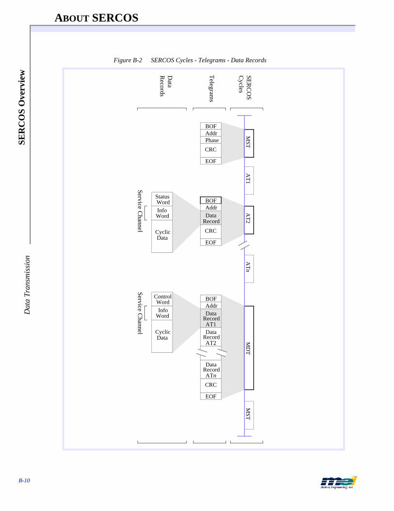
ABOUT SERCOS
B-10
SER
CO
S O
verv
iew
Dat
a Tr
ansm
issi
on
Figure B-2 SERCOS Cycles - Telegrams - Data Records
BOFAddrPhase
EOF
CRC
BOFAddrData
MST
Record
EOF
CRC
BOFAddr
EOF
DataRecordAT1Data
RecordAT2
DataRecordATn
CRC
AT1
AT2
ATn
MD
T
InfoWord
StatusWord
DataCyclic
MST
InfoWord
ControlWord
DataCyclic
Service Channel
Service Channel
SER
CO
S C
ycles
Telegram
s
Data
Records

ABOUT SERCOS
B-11
Telegram
s B
OF
Delim
iter
TelegramsThe controller (Master) communicates with the drives and I/O modules (Slaves) using tele-grams. A telegram is a structure that contains data, error checking and handshaking informa-tion. SERCOS supports three types of telegrams: Master Synchronization Telegram (MST), Master Data Telegram (MDT), and Amplifier Telegram (AT).
Each type of telegram contains 5 types of fields: BOF (beginning of frame), ADR (address), message field, FCS (frame check sequence), EOF (end of frame).
Figure B-3 General Telegram Structure
Figure B-4 Telegram Communications
BOF DelimiterAll telegrams have a BOF (beginning of frame) byte denoting the beginning of the telegram. The BOF is always 0111 1110.
Figure B-5 BOF Delimiter
1 byte
BOF Address (ADR)
Message Field FCS EOF
1 byte n bytes 2 bytes 1 byte
SERCOS “Overhead”
Application Data
SERCOS “Overhead”
Each Slave “sees” every MST and MDT transmitted. Each Slave waits until its proper time to trans-mit its AT to the Master.
Motor
Master
MST MDTAT3AT1 AT2 MST MDTAT3AT1 AT2
1 2 3 4 5
1
2
3
4
5
Each SERCOS cycle can be visualized as a stream of data/telegrams, where de-vices insert their telegrams into the stream at the proper time.
Slave 1
Drive
Slave 1
Drive
Slave 2
Drive
Slave 3
Master
Slave 2
Slave 3
Each Slave reads its data record in each MDT.
Telegrams travel in one direction only.
0347
0 1 1 1 1 1 1 0MSB LSB
1 byte

ABOUT SERCOS
B-12
Tel
egra
ms
AD
R T
arge
t Add
ress
ADR Target AddressAll telegrams have an ADR (address) byte, which denotes the address of a drive (Slave). In a telegram from the Master, the address specifies which drive the information is for. In a tele-gram from a Slave (drive), the address specifies the sourcing drive. The target addresses for the drives are valid if greater than 0 and less than 255. Typically, a drive’s address is set using a selector located physically on the drive.
Address 0 is the “no station” address, and is sometimes used to remove a drive from the ring logically, during troubleshooting. During non-cyclic operations (Phases 0 - 2), the Master can only communicate with one drive per cycle. During cyclic operations (Phases 3, 4), the Master can communicate with all drives.
Figure B-6 ADR Target Address
Message FieldEach Telegram (MST, AT, and MDT) contains a message field. The Message Field for the MST consists of one 8-bit word. The lower three bits of the MST contain Phase information. The Message Field for the AT consists of one Data Record. The Message Field for the MDT consists of one Data Record if the MDT’s target address is a specific drive. If the MDT’s Target address is all drives (255), then the Message Field for the MDT consists of one Data Record per drive in the system.
FCS (Frame Check Sequence)All telegrams have a two-byte FCS number used to check data integrity. The frame check se-quence (16 bits) is implemented according to ISO/IEC 3309, 4.5.2.
Figure B-7 FCS (Frame Check Sequence)
Table B-5 Address Values vs. Phases During Telegram Transmission
From To Telegram Non-Cyclic (Phases 0, 1, 2)
Cyclic (Phases 3, 4)
Master Slave MST 255 255
Master Slave MDT 1 ≤ ADR ≤ 255 255
Slave Master AT 1 ≤ ADR ≤ 254 1 ≤ ADR ≤ 254
0347
MSB LSB
broadcast address = 11111111B no-station address = 00000000B
1 byte
0347
LSB
8111215
MSB
2 bytes
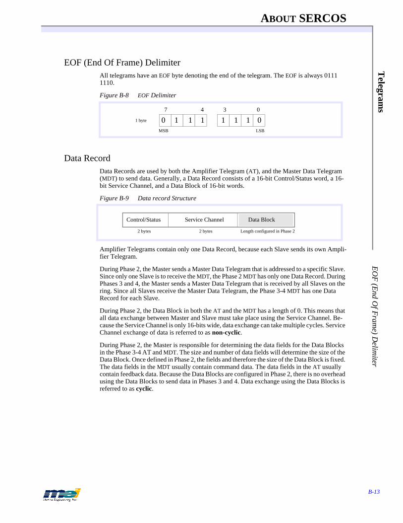
ABOUT SERCOS
B-13
Telegram
s E
OF
(End O
f Fram
e) Delim
iter
EOF (End Of Frame) DelimiterAll telegrams have an EOF byte denoting the end of the telegram. The EOF is always 0111 1110.
Figure B-8 EOF Delimiter
Data RecordData Records are used by both the Amplifier Telegram (AT), and the Master Data Telegram (MDT) to send data. Generally, a Data Record consists of a 16-bit Control/Status word, a 16-bit Service Channel, and a Data Block of 16-bit words.
Figure B-9 Data record Structure
Amplifier Telegrams contain only one Data Record, because each Slave sends its own Ampli-fier Telegram.
During Phase 2, the Master sends a Master Data Telegram that is addressed to a specific Slave. Since only one Slave is to receive the MDT, the Phase 2 MDT has only one Data Record. During Phases 3 and 4, the Master sends a Master Data Telegram that is received by all Slaves on the ring. Since all Slaves receive the Master Data Telegram, the Phase 3-4 MDT has one Data Record for each Slave.
During Phase 2, the Data Block in both the AT and the MDT has a length of 0. This means that all data exchange between Master and Slave must take place using the Service Channel. Be-cause the Service Channel is only 16-bits wide, data exchange can take multiple cycles. Service Channel exchange of data is referred to as non-cyclic.
During Phase 2, the Master is responsible for determining the data fields for the Data Blocks in the Phase 3-4 AT and MDT. The size and number of data fields will determine the size of the Data Block. Once defined in Phase 2, the fields and therefore the size of the Data Block is fixed. The data fields in the MDT usually contain command data. The data fields in the AT usually contain feedback data. Because the Data Blocks are configured in Phase 2, there is no overhead using the Data Blocks to send data in Phases 3 and 4. Data exchange using the Data Blocks is referred to as cyclic.
0347
0 1 1 1 1 1 1 0MSB LSB
1 byte
Service ChannelControl/Status
2 bytes 2 bytes Length configured in Phase 2
Data Block

ABOUT SERCOS
B-14
Tel
egra
ms
Mas
ter
Sync
hron
izat
ion
Tele
gram
Master Synchronization TelegramThe Master Controller uses master synchronization telegrams (MST) to coordinate its trans-mission cycle timing with the Slaves. The Master initiates a SERCOS cycle by transmitting an MST to all of the drives and I/O modules on the ring.The MST message field contains one 8-bit word, of which the three lowest bits determine the communication phase of the system. The MST is sent at the beginning of the SERCOS cycle in all communication phases.
Figure B-10 MST Telegram Structure
Table B-6 MST Telegram Fields
Field Bytes Description
BOF 1 Beginning of Frame. The BOF marks the start of a telegram.
ADR 1 The target address. In the MST, ADR = 255 (the broadcast address) during Phases 3 and 4.
Current Phase 1 The lower 3 bits designate the SERCOS phase (0 - 4)
FCS 2 Frame check sequence. The FCS field contains circular redundancy check (CRC) information.
EOF 1 End of Frame. The EOF marks the end of the telegram.
ADR FCS EOF
0 0 0 Phase 00 0 1 Phase 10 1 0 Phase 20 1 1 Phase 31 0 0 Phase 4
BOF
0 0 0 0 0
Close the SERCOS ringIdentify drives
Verify drive timingCyclic parameterization
Cyclic operations
1 byte 1 byte 1 byte 2 bytes 1 byte
Current Phase
Message Field
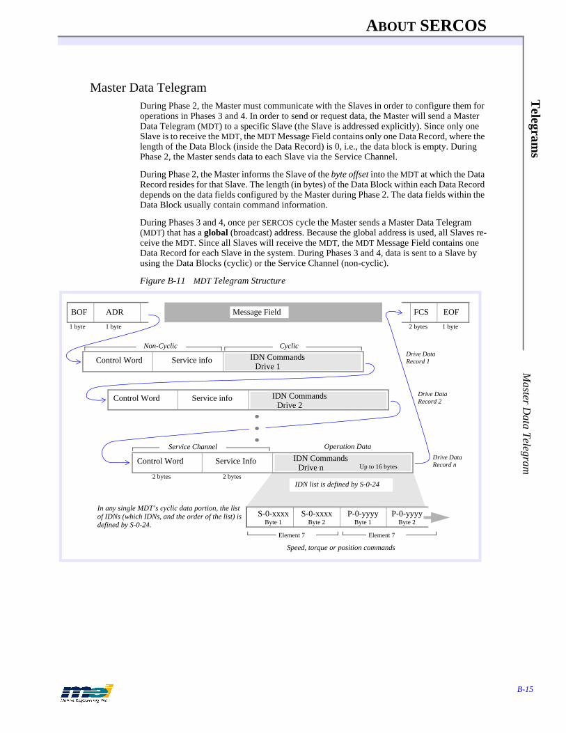
ABOUT SERCOS
B-15
Telegram
s M
aster Data Telegram
Master Data TelegramDuring Phase 2, the Master must communicate with the Slaves in order to configure them for operations in Phases 3 and 4. In order to send or request data, the Master will send a Master Data Telegram (MDT) to a specific Slave (the Slave is addressed explicitly). Since only one Slave is to receive the MDT, the MDT Message Field contains only one Data Record, where the length of the Data Block (inside the Data Record) is 0, i.e., the data block is empty. During Phase 2, the Master sends data to each Slave via the Service Channel.
During Phase 2, the Master informs the Slave of the byte offset into the MDT at which the Data Record resides for that Slave. The length (in bytes) of the Data Block within each Data Record depends on the data fields configured by the Master during Phase 2. The data fields within the Data Block usually contain command information.
During Phases 3 and 4, once per SERCOS cycle the Master sends a Master Data Telegram (MDT) that has a global (broadcast) address. Because the global address is used, all Slaves re-ceive the MDT. Since all Slaves will receive the MDT, the MDT Message Field contains one Data Record for each Slave in the system. During Phases 3 and 4, data is sent to a Slave by using the Data Blocks (cyclic) or the Service Channel (non-cyclic).
Figure B-11 MDT Telegram Structure
Non-Cyclic Cyclic
ADRBOF FCS EOF
Service info
Service Info
Control Word
Control Word
S-0-xxxxByte 1
S-0-xxxxByte 2
P-0-yyyyByte 1
P-0-yyyyByte 2
Operation Data
Speed, torque or position commands
2 bytes 2 bytes
1 byte 1 byte 2 bytes 1 byte
Drive Data Record 1
Drive Data Record 2
Drive Data Record n
IDN list is defined by S-0-24
In any single MDT’s cyclic data portion, the list of IDNs (which IDNs, and the order of the list) is defined by S-0-24.
Element 7 Element 7
Service Channel
Service infoControl Word
Message Field
IDN CommandsDrive n Up to 16 bytes
IDN CommandsDrive 1
IDN CommandsDrive 2
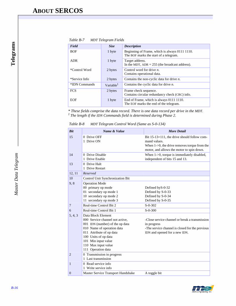
ABOUT SERCOS
B-16
Tel
egra
ms
Mas
ter
Dat
a Te
legr
am
* These fields comprise the data record. There is one data record per drive in the MDT.1 The length if the IDN Commands field is determined during Phase 2.
Table B-7 MDT Telegram Fields
Field Size Description
BOF 1 byte Beginning of Frame, which is always 0111 1110.The BOF marks the start of a telegram.
ADR 1 byte Target address. In the MDT, ADR = 255 (the broadcast address).
*Control Word 2 bytes Control word for drive n. Contains operational data.
*Service Info 2 bytes Contains the non-cyclic data for drive n.
*IDN Commands Variable1 Contains the cyclic data for drive n.
FCS 2 bytes Frame check sequence. Contains circular redundancy check (CRC) info.
EOF 1 byte End of Frame, which is always 0111 1110. The EOF marks the end of the telegram.
Table B-8 MDT Telegram Control Word (Same as S-0-134)
Bit Name & Value More Detail
15 0 Drive OFF1 Drive ON
Bit 15-13=111, the drive should follow com-mand values. When 1->0, the drive removes torque from the motor, and allows the motor to spin down.
14 0 Drive Disable1 Drive Enable
When 1->0, torque is immediately disabled, independent of bits 15 and 13.
13 0 Drive Halt1 Drive Restart
12, 11 Reserved10 Control Unit Synchronization Bit9, 8 Operation Mode
00 primary op mode01 secondary op mode 110 secondary op mode 211 secondary op mode 3
Defined byS-0-32Defined by S-0-33Defined by S-0-34Defined by S-0-35
7 Real-time Control Bit 2 S-0-3026 Real-time Control Bit 1 S-0-3005, 4, 3 Data Block Element
000 Service channel not active, 001 IDN (number) of the op data 010 Name of operation data011 Attribute of op data 100 Units of op data101 Min input value110 Max input value111 Operation data
-Close service channel or break a transmission in progress-The service channel is closed for the previous IDN and opened for a new IDN.
2 0 Transmission in progress1 Last transmission
1 0 Read service info1 Write service info
0 Master Service Transport Handshake A toggle bit
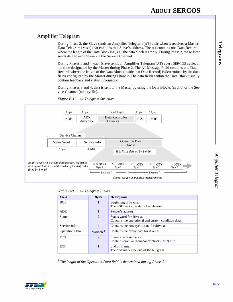
ABOUT SERCOS
B-17
Telegram
s A
mplifier Telegram
Amplifier TelegramDuring Phase 2, the Slave sends an Amplifier Telegram (AT) only when it receives a Master Data Telegram (MDT) that contains that Slave’s address. The AT contains one Data Record where the length of the Data Block is 0, i.e., the data block is empty. During Phase 2, the Master sends data to each Slave via the Service Channel.
During Phases 3 and 4, each Slave sends an Amplifier Telegram (AT) every SERCOS cycle, at the time designated by the Master during Phase 2. The AT Message Field contains one Data Record, where the length of the Data Block (inside that Data Record) is determined by the data fields configured by the Master during Phase 2. The data fields within the Data Block usually contain feedback and status information.
During Phases 3 and 4, data is sent to the Master by using the Data Blocks (cyclic) or the Ser-vice Channel (non-cyclic).
Figure B-12 AT Telegram Structure
1 The length of the Operation Data field is determined during Phase 2.
Table B-9 AT Telegram Fields
Field Bytes Description
BOF 1 Beginning of Frame. The BOF marks the start of a telegram.
ADR 1 Sender’s address.
Status 2 Status word for drive n. Contains the operational and current condition data.
Service Info 2 Contains the non-cyclic data for drive n.
Operation Data Variable1 Contains the cyclic data for drive n.
FCS 2 Frame check sequence. Contains circular redundancy check (CRC) info.
EOF 1 End of Frame. The EOF marks the end of the telegram.
ADRdrive xxx
FCS EOFBOF
S-0-xxxxByte 1
S-0-xxxxByte 2
P-0-yyyyByte 1
P-0-yyyyByte 2
P-0-yyyyByte 3
1 byte 1 byte Up to 20 bytes 1 byte 1 byte
2 bytes
Speed, torque or position measurements
In any single AT’s cyclic data portion, the list of IDNs (which IDNs, and the order of the list) is de-fined by S-0-16.
IDN list is defined by S-0-16
Element 7 Element 7
Service infoStatus WordUp to 16 bytes
2 bytes
Service Channel
Operation DataCyclic
Data Record forDrive xx
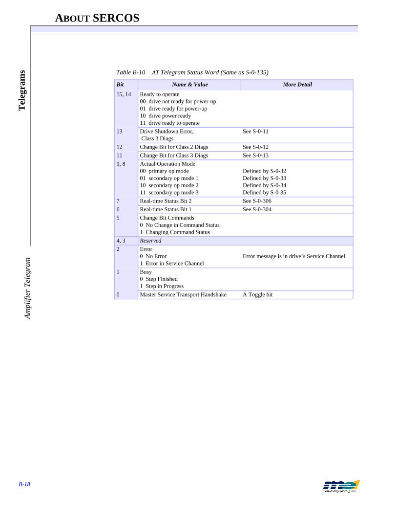
ABOUT SERCOS
B-18
Tel
egra
ms
Am
plifi
er T
eleg
ram
Table B-10 AT Telegram Status Word (Same as S-0-135)
Bit Name & Value More Detail
15, 14 Ready to operate00 drive not ready for power-up01 drive ready for power-up10 drive power ready11 drive ready to operate
13 Drive Shutdown Error, Class 3 Diags
See S-0-11
12 Change Bit for Class 2 Diags See S-0-1211 Change Bit for Class 3 Diags See S-0-139, 8 Actual Operation Mode
00 primary op mode01 secondary op mode 110 secondary op mode 211 secondary op mode 3
Defined by S-0-32Defined by S-0-33Defined by S-0-34Defined by S-0-35
7 Real-time Status Bit 2 See S-0-3066 Real-time Status Bit 1 See S-0-3045 Change Bit Commands
0 No Change in Command Status1 Changing Command Status
4, 3 Reserved2 Error
0 No Error1 Error in Service Channel
Error message is in drive’s Service Channel.
1 Busy0 Step Finished1 Step in Progress
0 Master Service Transport Handshake A Toggle bit
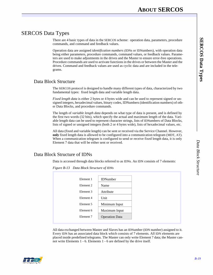
ABOUT SERCOS
B-19
SER
CO
S Data T
ypes D
ata Block Structure
SERCOS Data TypesThere are 4 basic types of data in the SERCOS scheme: operation data, parameters, procedure commands, and command and feedback values.
Operation data are assigned identification numbers (IDNs or IDNumbers), with operation data being either parameters, procedure commands, command values, or feedback values. Parame-ters are used to make adjustments in the drives and the Master to ensure error-free operations. Procedure commands are used to activate functions in the drives or between the Master and the drives. Command and feedback values are used as cyclic data and are included in the tele-grams.
Data Block StructureThe SERCOS protocol is designed to handle many different types of data, characterized by two fundamental types: fixed length data and variable length data.
Fixed length data is either 2 bytes or 4 bytes wide and can be used to represent signed or un-signed integers, hexadecimal values, binary codes, IDNumbers (identification numbers) of oth-er Data Blocks, and procedure commands.
The length of variable length data depends on what type of data is present, and is defined by the first two words (32 bits), which specify the actual and maximum length of the data. Vari-able length data can be used to represent character strings, lists of IDNumbers of Data Blocks, lists of signed or unsigned integers (both 2 or 4 bytes wide), lists of hexadecimal values, etc.
All data (fixed and variable length) can be sent or received via the Service Channel. However, only fixed length data is allowed to be configured into a communication telegram (MDT, AT). When a communication telegram is configured to send or receive fixed length data, it is only Element 7 data that will be either sent or received.
Data Block Structure of IDNsData is accessed through data blocks referred to as IDNs. An IDN consists of 7 elements:
Figure B-13 Data Block Structure of IDNs
All data exchanged between Master and Slaves has an IDNumber (IDN number) assigned to it. Every IDN has an associated data block which consists of 7 elements. All IDN elements are placed inside predefined telegrams. The Master can only write Element 7 data; the Master can-not write Elements 1 - 6. Elements 1 - 6 are defined by the drive itself.
Operation Data
IDNumber
Name
Attribute
Unit
Minimum Input
Maximum Input
Element 1
Element 2
Element 3
Element 4
Element 5
Element 6
Element 7

ABOUT SERCOS
B-20
SER
CO
S D
ata
Typ
esE
lem
ent 1
: ID
Num
bers
Element 1: IDNumbersEach Data Block has a number assigned to it for identification purposes, called the IDNumber. The IDNumber is represented as either S-X-XXXX or P-X-XXXX. S denotes a Data Block that is defined by the SERCOS Specification. P denotes a Data Block that is defined by the manu-facturer. The first ‘X’ identifies the “data set” that the Data Block belongs to. According to the SERCOS Specification, it is possible to switch between data sets.
Up to 65,536 (216) IDNumbers can be used to identify data. The first half of the possible IDNumbers (0 - 32,767 or 215) are reserved for standard IDNs (or S-x-xxxx), while the second half (32768 - 65535) are reserved for product-specific IDNs (or P-x-xxxx, as specified by the device manufacturer).
Figure B-14 IDNumber Structure
Table B-11 The 7 Elements of an IDN
Element Description Data Type1 IDNumber
(Identification number)
binaryExpressed as either S-X-XXXX or P-X-XXXX. S denotes IDNs that are defined by the SERCOS Specifica-tion. P denotes IDNs that are defined by the manufacturer of the device.
2 Name variable length string Contains the name of the IDN.
3 Attribute 32 bit binaryContains information about conversion factors and data representation (signed or unsigned integer, fixed or vari-able length data, etc.)
4 Unit variable length string Contains a representation of the units for the data.
5 Minimum input value 1 or 2 words
6 Maximum input value 1 or 2 words
7 Operation Data 1 or 2 words, or string
03478111215
x y y y z z z z z z z z z z z z
Type of IDN
Parameter Set Data Block Number
x - y - zzzz
Data Block Number
Parameter Set
Type of IDN
14
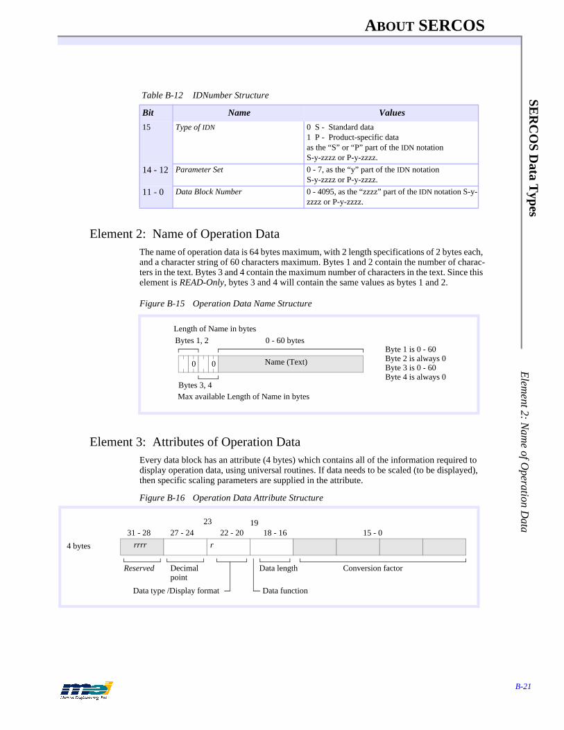
ABOUT SERCOS
B-21
SER
CO
S Data T
ypes E
lement 2: N
ame of O
peration Data
Element 2: Name of Operation DataThe name of operation data is 64 bytes maximum, with 2 length specifications of 2 bytes each, and a character string of 60 characters maximum. Bytes 1 and 2 contain the number of charac-ters in the text. Bytes 3 and 4 contain the maximum number of characters in the text. Since this element is READ-Only, bytes 3 and 4 will contain the same values as bytes 1 and 2.
Figure B-15 Operation Data Name Structure
Element 3: Attributes of Operation DataEvery data block has an attribute (4 bytes) which contains all of the information required to display operation data, using universal routines. If data needs to be scaled (to be displayed), then specific scaling parameters are supplied in the attribute.
Figure B-16 Operation Data Attribute Structure
Table B-12 IDNumber Structure
Bit Name Values
15 Type of IDN 0 S - Standard data1 P - Product-specific dataas the “S” or “P” part of the IDN notation S-y-zzzz or P-y-zzzz.
14 - 12 Parameter Set 0 - 7, as the “y” part of the IDN notation S-y-zzzz or P-y-zzzz.
11 - 0 Data Block Number 0 - 4095, as the “zzzz” part of the IDN notation S-y-zzzz or P-y-zzzz.
Bytes 1, 2
Name (Text)
Bytes 3, 4
0 0
Byte 1 is 0 - 60Byte 2 is always 0Byte 3 is 0 - 60Byte 4 is always 0
Length of Name in bytes
Max available Length of Name in bytes
0 - 60 bytes
4 bytes
Conversion factor
31 - 28 27 - 24 22 - 20 15 - 018 - 16
Decimal point
Reserved
r
19
Data type /Display format Data function
Data length
23
rrrr

ABOUT SERCOS
B-22
SER
CO
S D
ata
Typ
esE
lem
ent 4
: Ope
ratio
n D
ata
Uni
t
Element 4: Operation Data UnitThe operation data unit is 16 bytes maximum, with 2 length specifications of 2 bytes each, and a character string of 12 characters maximum. Bytes 1 and 2 contain the number of characters in the text. Bytes 3 and 4 contain the maximum number of characters in the text. Since this el-ement is READ-Only, bytes 3 and 4 will contain the same values as bytes 1 and 2.
Table B-13 Operation Data Attribute Structure
Bits Name Values
31 - 28 Reserved27 - 24 Number of places after the
decimal point
Indicates the position of the decimal point in the data to be displayed. Basi-cally, it’s the exponent “x” in 10-x.
000 No places after decimal point001 1 place after decimal point010 2 places after decimal point *111 15 places after decimal point
23 Reserved22 - 20 Data Type & Display Format
Used to convert the operation data, and min/max input values to the cor-rect display format.
Data Type Display Format000 binary number binary001 unsigned integer unsigned decimal010 integer signed decimal011 unsigned integer hexadecimal100 extended char set text101 unsigned integer IDN number010 Reserved 111 Reserved
19 Function of Operation Data
Indicates whether this data calls a pro-cedure in a drive
0 Operation data or parameter1 Procedure command
18 - 16 Data Length
The data length is required so that the Master is able to complete Service Channel data transfers correctly.
000 Reserved001 Operation data is 2 bytes long010 Operation data is 4 bytes long011 Reserved100 Variable length with 1-byte data strings101 Variable length with 2-byte data strings110 Variable length with 4-byte data strings111 Reserved
15 - 0 Conversion Factor An unsigned integer used to convert numeric data to display format. Is set to 1 when it is not needed for data display (e.g., binary display or a character string).

ABOUT SERCOS
B-23
SER
CO
S Data T
ypes E
lement 5: M
inimum
Input Value of O
peration Data
Figure B-17 Operation Data Unit Structure
Element 5: Minimum Input Value of Operation DataThe minimum input value is the smallest numerical value for operation data that the drive can process. When the Master writes a value to the drive that is less than the minimum value, the drive ignores it and continues to use the previous operation data.
When the operation data is of variable length or a binary number is used, there is no minimum input value of operation data.
Element 6: Maximum Input Value of Operation DataThe maximum input value is the largest numerical value for operation data that the drive can process. When the Master writes a value to the drive that is more than the maximum value, the drive ignores it and continues to use the previous operation data.
When the operation data is of variable length or a binary number is used, there is no maximum input value of operation data.
Element 7: Operation DataIn terms of length, there are 3 types of operation data:
fixed length with 2 bytesfixed length with 4 bytesvariable length up to 65,532 bytes
in 1 byte (char), 2 byte, or 4 byte valuesBytes 1 and 2 contain the number of bytes in the text. Bytes 3 and 4 contain the max number of bytes available in the text. Data in the text may be 1 byte, 2 bytes, or 4 bytes wide.
Figure B-18 Operation Data Variable Length Structure
Bytes 1, 2
Unit (Text)
Bytes 3, 4
Length of Unit in bytes
Max available Length of Unit in bytes
0 - 12 bytesByte 1 is low byteByte 2 is high byteByte 3 is low byteByte 4 is high byte
Bytes 1, 2
Text
Bytes 3, 4
Byte 1 is low byteByte 2 is high byteByte 3 is low byteByte 4 is high byte
Length of Operation Data in bytes
Max available Length of Operation Data in bytes
0 - 60 bytes (as specified by bytes 3, 4)
Length is from 1 to 65,532 (FFFCH)

ABOUT SERCOS
B-24
SER
CO
S D
ata
Typ
esP
roce
dure
s
ProceduresMany Slaves (drives) come with preprogrammed procedures that the Slave is able to execute without assistance from the Master. Each of these procedures is assigned a Data Block. The Master controls a procedure by reading and writing to Element 7 of the procedure’s Data Block. The Master can initiate, interrupt, or cancel a procedure at any time by setting or clear-ing bits in Element 7 of the procedure’s Data Block.
Bits 0 and 1 are responsible for respectively setting and enabling the procedure command. Once set and enabled, the Slave will begin execution of the procedure. To indicate that the pro-cedure is executing, the Slave sets bit 2. When the procedure has finished executing, the Slave clears bit 2 and sets the Procedure Command Change Bit in the Drive Status Word S-0-134. If an error has occurred when executing the procedure, the Slave will set bit 3 of Element 7 of the procedure’s Data Block and will also set the Procedure Command Change Bit in the Drive Sta-tus Word S-0-135. In either case (successful execution or failure), the Master must cancel the procedure by clearing bits 0 and 1 of the procedure.
In SERCOS, in order for a Master to execute a procedure,
1. The Master writes 0x3 to Element 7 of the desired IDN procedure, which sets and en-ables the procedure.
2. The Master reads Element 7 of the desired IDN procedure and checks bits 2 & 3 to see if the procedure has finished executing or if there is an error.
3. After reading that the procedure has executed, the Master writes 0x0 to Element 7 of the particular procedure, which cancels the procedure.
Figure B-19 Procedure Element 7: Bit Definitions
0123478111215
0 0 0 0 0 0 0 0 0 0 0 0 0 0
Interrupt procedure execution 0Enable procedure execution 1
WRITE
Cancel procedure 0Set procedure 1
0123478111215
0 0 0 0 0 0 0 0 0 0 0
Procedure executed correctly 0Procedure not yet executed 1
READ
Procedure execution interrupted in drive 0Procedure execution enabled in drive 1
(Status)
Operation data is valid 0Operation data is not valid 1
No procedure error 0Error: procedure cannot execute 1
Procedure not set in drive (by Master) 0Procedure set in drive 1
(Commands)From Master
From Slave

ABOUT SERCOS
B-25
SER
CO
S Com
munications
Synchronization
SERCOS Communications
SynchronizationThe Master is responsible for sending a synchronization telegram (MST) at the beginning of each communication cycle. All Slaves (drives) will receive the MST and reset their clocks. In this way, all Slaves will run in phase lock with the Master’s clock.
Because all Slaves are in phase lock with the Master’s clock, commands can be made active in all of the Slaves at the same instant. This means that the Master can coordinate motion between all axes without propagation effects distorting the motion profile. Feedback from the Slaves is handled in a similar manner, and is latched in all Slaves at the same instant.
Ring TimingData is sent and received by the Master and Slaves through communication telegrams. The communication telegrams are organized over the SERCOS cycle in the manner shown in the next figure.
The SERCOS ring timing is based on the data to be placed in the telegrams (AT, MDT), and on 6 drive parameters that are determined by the type and features of a drive (or drives), and 6 parameters that are written from the Master, with some of these parameters derived or calcu-lated from the drive’s timing parameters. The times at which the MDT and AT are sent (relative to the sending of the MST) are determined by the Master and sent to the Slaves during initial-ization.
During Phase 2, the Master reads parameters from the drives that determine what and when the drives are able to transmit and receive. Using this information and the desired telegram con-tents, baud rate and cycle time, the Master determines the timing and telegram parameters for each drive. The Master then writes these parameters to the drives.

ABOUT SERCOS
B-26
SER
CO
S C
omm
unic
atio
nsR
ing
Tim
ing
Figure B-20 SERCOS Ring Timing
Feed
back
Acq
uisi
tion
Cap
ture
Poi
nt
T_A
TAT
MST
AT0
T_1m
in
AT
1A
TnM
DT
MST
MD
T S
tart
ing
Tim
eT
_2 T1 0
T1 1
T1 n
T_A
TMT
T_3
TMTS
G
T4
mus
t occ
ur
befo
re T
_5 S
tart
s
Min
Fee
dbac
k P
roc
Tim
e
T_5
T_4
Tim
ing
writ
ten
by M
aste
rT
_Ncy
cS-
0-1
T_S
cyc
S-0-
2T
_1S-
0-6
T_2
S-0-
89T
_3S-
0-8
T_4
S-0-
7
Tx-t
o-Tc
Tra
nsiti
on T
ime
TMTS
Y
T3
mus
t occ
ur
afte
r TM
TSG
an
d be
fore
st
art o
f nex
t M
ST
T4
sign
als
the
star
t of f
eedb
ack
proc
essi
ng, a
nd
mus
t occ
ur s
o th
at th
ere
is e
noug
h tim
e fo
r pro
cess
-in
g to
fini
sh b
efor
e th
e en
d of
the
next
MST
.
T3
sign
als
the
time
whe
n th
e co
mm
ands
are
val
id.
T_N
cyc
Cm
d V
alue
Val
id T
ime
Min
AT
Tx
Star
ting
Tim
e AT
Tx
Star
ting
Tim
es
T_4
≤ T
_Scy
c - T
_5
T1 n
≥ T
1 _m
inn
T_3
≥ T
_2 +
TM
TSG
+ M
DT
Tx ti
me1
T_2
≥ T
1 n +
T_A
TM
Tn
DR
IV
DR
IV
DR
IV
DR
IV
S-0-
90
S-0-
4
S-0-
87S-
0-3
DR
IVS-
0-5
DR
IVS-
0-88
1 MD
T Tx
tim
e de
pend
s on
the
num
ber o
f sla
ves
and
the
amou
nt o
f dat
a se
nt to
the
slav
es. T
he M
aste
r mus
t cal
cula
te th
e M
DT
Tx ti
me
duri
ng P
hase
2.
Tim
ing
that
is d
eter
min
ed b
y th
e D
rive
T_1m
inS-
0-3
T_5
S-0-
5T_
AT
AT
S-0-
87T_
AT
MT
S-0-
4T_
MT
SYS-
0-88
T_M
TSG
S-0-
90
DR
IVS-
0-xx
xx
Con
trol
Uni
t Cyc
le T
ime
S-0-
1
S-0-
89
S-0-
6
S-0-
7
S-0-
8
S-0-
xxxx
Com
m C
ycle
Tim
eT
_Scy
cS-
0-2
T_N
cyc=
n *
T_S
cyc
(n=
1, 2
, 3 .
. .)
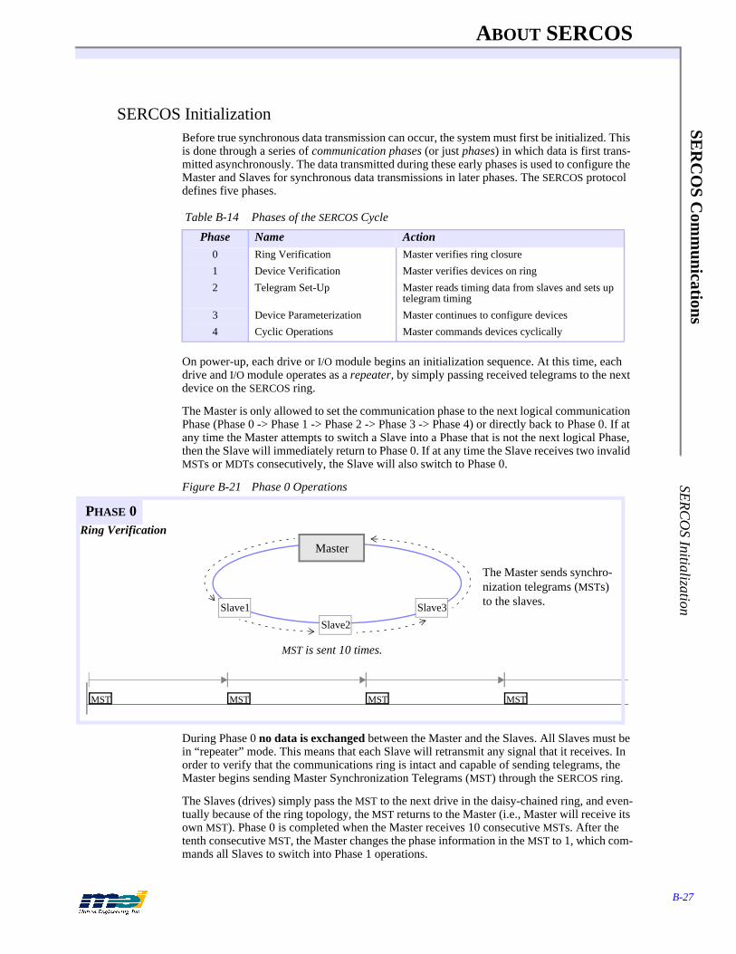
ABOUT SERCOS
B-27
SER
CO
S Com
munications
SER
CO
S Initialization
SERCOS InitializationBefore true synchronous data transmission can occur, the system must first be initialized. This is done through a series of communication phases (or just phases) in which data is first trans-mitted asynchronously. The data transmitted during these early phases is used to configure the Master and Slaves for synchronous data transmissions in later phases. The SERCOS protocol defines five phases.
On power-up, each drive or I/O module begins an initialization sequence. At this time, each drive and I/O module operates as a repeater, by simply passing received telegrams to the next device on the SERCOS ring.
The Master is only allowed to set the communication phase to the next logical communication Phase (Phase 0 -> Phase 1 -> Phase 2 -> Phase 3 -> Phase 4) or directly back to Phase 0. If at any time the Master attempts to switch a Slave into a Phase that is not the next logical Phase, then the Slave will immediately return to Phase 0. If at any time the Slave receives two invalid MSTs or MDTs consecutively, the Slave will also switch to Phase 0.
Figure B-21 Phase 0 Operations
During Phase 0 no data is exchanged between the Master and the Slaves. All Slaves must be in “repeater” mode. This means that each Slave will retransmit any signal that it receives. In order to verify that the communications ring is intact and capable of sending telegrams, the Master begins sending Master Synchronization Telegrams (MST) through the SERCOS ring.
The Slaves (drives) simply pass the MST to the next drive in the daisy-chained ring, and even-tually because of the ring topology, the MST returns to the Master (i.e., Master will receive its own MST). Phase 0 is completed when the Master receives 10 consecutive MSTs. After the tenth consecutive MST, the Master changes the phase information in the MST to 1, which com-mands all Slaves to switch into Phase 1 operations.
Table B-14 Phases of the SERCOS Cycle
Phase Name Action0 Ring Verification Master verifies ring closure
1 Device Verification Master verifies devices on ring
2 Telegram Set-Up Master reads timing data from slaves and sets up telegram timing
3 Device Parameterization Master continues to configure devices
4 Cyclic Operations Master commands devices cyclically
The Master sends synchro-nization telegrams (MSTs) to the slaves.
MST is sent 10 times.
Ring Verification
Slave1
Master
Slave2
Slave3
MST MST MST MST
PHASE 0
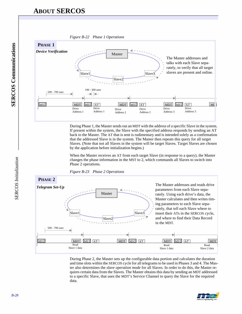
ABOUT SERCOS
B-28
SER
CO
S C
omm
unic
atio
nsSE
RC
OS
Initi
aliz
atio
n
Figure B-22 Phase 1 Operations
During Phase 1, the Master sends out an MDT with the address of a specific Slave in the system. If present within the system, the Slave with the specified address responds by sending an AT back to the Master. The AT that is sent is rudimentary and is intended solely as a confirmation that the addressed Slave is in the system. The Master then repeats this query for all target Slaves. (Note that not all Slaves in the system will be target Slaves. Target Slaves are chosen by the application before initialization begins.)
When the Master receives an AT from each target Slave (in response to a query), the Master changes the phase information in the MST to 2, which commands all Slaves to switch into Phase 2 operations.
Figure B-23 Phase 2 Operations
During Phase 2, the Master sets up the configurable data portion and calculates the duration and time slots within the SERCOS cycle for all telegrams to be used in Phases 3 and 4. The Mas-ter also determines the slave operation mode for all Slaves. In order to do this, the Master re-quires certain data from the Slaves. The Master obtains this data by sending an MDT addressed to a specific Slave, that uses the MDT’s Service Channel to query the Slave for the required data.
Slave1
MasterDevice Verification
Slave2
Slave3
The Master addresses and talks with each Slave sepa-rately, to verify that all target slaves are present and online.
Drive Address 1
Drive Address 1
Drive Address 3
500 - 700 usec100 - 300 usec
MST MDT MST MDTAT MST MDTAT MST MDTATDrive Address 2
Drive Address 2
Drive Address 3
PHASE 1
Slave1
Master
Telegram Set-Up
Slave2
Slave3
500 - 700 usec
The Master addresses and reads drive parameters from each Slave sepa-rately. Using each drive’s data, the Master calculates and then writes tim-ing parameters to each Slave sepa-rately, that tell each Slave where to insert their ATs in the SERCOS cycle, and where to find their Data Record in the MDT.
Read Slave 1 data
Read Slave 1 data
Read Slave 2 data
MST MDT MST MDT MST MDT MST MDTAT AT AT
PHASE 2

ABOUT SERCOS
B-29
SER
CO
S Com
munications
SER
CO
S Initialization
The Slave responds by sending an AT containing the appropriate data, in the AT’s Service Channel. Once the Master has determined all parameters, it sends them to each Slave via the MDT’s Service Channel. In Phase 2, the Service Channel is active in both MDTs and ATs.
First, the Master configures each drive’s communication parameters for real-time synchronous operation; then the Master configures the drive’s operational parameters. These operational pa-rameters are specific to each drive, and are based on the drive’s operation mode(s), its support-ed features, and the manufacturer. Note that the drive operation IDNs can be configured during both Phase 2 and Phase 3.
Once all data is transmitted to the Slaves, the Master will initiate the Communication Phase 3 Transition Check S-0-127 procedure for each Slave. In order to successfully execute the Phase 3 Transition Check, the following IDNs must contain valid data:
S-0-1 Control Unit Cycle Time (T_NCYC)S-0-2 Communication Cycle Time (T_SCYC)S-0-6 AT Transmission Starting Time (T_1)S-0-7 Feedback Acquisition Capture Point (T_4)S-0-8 Command Value Valid Time (T_5)S-0-9 Position of Data Record in MDTS-0-10 Length of MDTS-0-15 Telegram Type ParameterS-0-16 Configuration List of ATS-0-24 Configuration List of MDTS-0-32 Primary Operation ModeS-0-89 MDT Transmission Starting Time (T_2)P-0-11 DSP Sub SamplesP-0-24 Encoder Counts per Commutation CycleP-0-25 Electrical Cycles per Commutation Cycle
Note that for some of the IDNs listed, the default values are valid. The Communication Phase 3 Transition Check checks the validity of all the data, and if all the data is valid, then the pro-cedure executes successfully. If any data is not valid, the procedure fails and the IDN number of the invalid data is placed in IDN-List of Invalid Operation Data for CP2 S-0-21.
After all Slaves have completed the procedure successfully, the Master changes the phase in-formation in the MST to 3, which commands all Slaves to switch into communication Phase 3.
Figure B-24 Phase 3 Operations
In Phase 3, the real-time synchronous and asynchronous communication starts, and the Master uses the Service Channel to configure and parameterize (write parameters to) the Slaves. The
Slave1
Master
Device Parameterization
Slave2
Slave3
All communication telegrams are now valid. To continue configur-ing the drives, the Master writes application commands and parameters over the Service Channel. ATs and MDTs are sent cycli-cally, but cyclic data is not valid.
MST MDTAT3AT1 AT2 MST MDTAT3AT1 AT2 MST MDTAT3AT1 AT2 MST MDTAT3AT1 AT2
PHASE 3
ABOUT SERCOS
B-30
SER
CO
S C
omm
unic
atio
nsSE
RC
OS
Initi
aliz
atio
n
parameters set in Phase 3 are application-oriented (e.g., conversion factors). During Phase 3, all communication telegram parameters sent in Phase 2 become active. Note that although Con-figurable Data (in ATs and MDTs) is present in the communication telegrams, some of that Configurable Data may not be valid until Phase 4.
The Master will still send the MST at the beginning of the SERCOS cycle, but will now also send an MDT with a global address at a specific time (all Slaves will receive a global telegram). Each Slave will transmit its AT during its specified time slot. The communication telegrams now contain the Control/Status Word, a Service Channel, and the Configurable Data.
When the Master has finished sending parameters to the Slaves, it will initiate the Communi-cation Phase 4 Transition Check S-0-128 procedure for each Slave. After all Slaves have com-pleted the procedure successfully, the Master changes the phase information in the MST to 4, which commands all Slaves to switch into Phase 4. In order to successfully execute the Phase 4 Transition Check, the following IDNs must contain valid data:
S-0-115 Position Feedback TypeS-0-76 Position Data Scaling TypeS-0-118 Resolution of Linear FeedbackS-0-77 Linear Position Data Scaling FactorS-0-78 Linear Position Data Scaling ExponentS-0-116 Resolution of Rotational Feedback 1S-0-79 Rotational Position ResolutionS-0-44 Velocity Data Scaling TypeS-0-45 Velocity Data Scaling FactorS-0-46 Velocity Data Scaling ExponentS-0-160 Acceleration Data Scaling TypeS-0-161 Acceleration Data Scaling FactorS-0-162 Acceleration Data Scaling exponentS-0-86 Torque/Force Data Scaling TypeS-0-93 Torque/Force Data Scaling FactorS-0-94 Torque/Force Data Scaling ExponentS-0-138 Bipolar Acceleration LimitP-0-3 Enable Default Conversion Factors
Note that for some of the IDNs listed, the default values are valid. The Communication Phase 4 Transition Check checks the validity of all the data, and if all the data is valid, then the pro-cedure executes successfully. If any data is not valid, the procedure fails and the IDN number of the invalid data is placed in IDN-List of Invalid Operation Data for CP3 S-0-22.
If the Communication Phase 4 Transition Check executes successfully and the Phase informa-tion in the MST is equal to 4, the Master switches the drives to Phase 4.
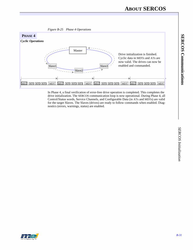
ABOUT SERCOS
B-31
SER
CO
S Com
munications
SER
CO
S Initialization
Figure B-25 Phase 4 Operations
In Phase 4, a final verification of error-free drive operation is completed. This completes the drive initialization. The SERCOS communication loop is now operational. During Phase 4, all Control/Status words, Service Channels, and Configurable Data (in ATs and MDTs) are valid for the target Slaves. The Slaves (drives) are ready to follow commands when enabled. Diag-nostics (errors, warnings, status) are enabled.
Slave1
Master
Cyclic Operations
Slave2
Slave3
Drive initialization is finished.Cyclic data in MDTs and ATs are now valid. The drives can now be enabled and commanded.
MST MDTAT3AT1 AT2 MST MDTAT3AT1 AT2 MST MDTAT3AT1 AT2 MST MDTAT3AT1 AT2
PHASE 4

ABOUT SERCOS
B-32
SER
CO
S C
omm
unic
atio
nsSE
RC
OS
Initi
aliz
atio
n

INDEX
Index-1
Symbols
Symbols#defines
aux filter parameters . . . . . . . . . . . . . . . . . . . . . . . . 2-8axis status . . . . . . . . . . . . . . . . . . . . . . . . . . . . . . . . 2-7DSP config . . . . . . . . . . . . . . . . . . . . . . . . . . . . . . . 2-6DSP software rev . . . . . . . . . . . . . . . . . . . . . . . . . . 2-6errors . . . . . . . . . . . . . . . . . . . . . . . . . . . . . . . . . . . . 2-9events . . . . . . . . . . . . . . . . . . . . . . . . . . . . . . . . . . . 2-7feedback devices . . . . . . . . . . . . . . . . . . . . . . . . . . 2-11high/low values . . . . . . . . . . . . . . . . . . . . . . . . . . . . 2-6home/index config . . . . . . . . . . . . . . . . . . . . . . . . . 2-11I/O port . . . . . . . . . . . . . . . . . . . . . . . . . . . . . . . . . . 2-6integration modes . . . . . . . . . . . . . . . . . . . . . . . . . 2-11master/slave control . . . . . . . . . . . . . . . . . . . . . . . 2-11PID filter parameters . . . . . . . . . . . . . . . . . . . . . . . . 2-8position limits status . . . . . . . . . . . . . . . . . . . . . . . . 2-7step output pulse speeds . . . . . . . . . . . . . . . . . . . . 2-12that define software versions . . . . . . . . . . . . . . . . . . 1-4trigger sense . . . . . . . . . . . . . . . . . . . . . . . . . . . . . 2-12TRUE/FALSE values . . . . . . . . . . . . . . . . . . . . . . . 2-6
1, 2, 38AXIS.ABS firmware file . . . . . . . . . . . . . . . . . . . . . . . . 1-88AXISSER.ABS firmware file . . . . . . . . . . . . . . . . . . . . 1-8
Aabort event functions . . . . . . . . . . . . . . . . . . . . . . . . . . . 3-52action frames functions . . . . . . . . . . . . . . . . . . . . . . . . . 3-92actual position . . . . . . . . . . . . . . . . . . . . . . . . . . . . . . . . A-5ADR (SERCOS)
"no station" address . . . . . . . . . . . . . . . . . . . . . . . B-12address field of telegrams . . . . . . . . . . . . . . . . . . B-12bit definitions . . . . . . . . . . . . . . . . . . . . . . . . . . . B-12broadcast address . . . . . . . . . . . . . . . . . . . . . . . . B-12
amp enable output config functions . . . . . . . . . . . . . . . 2-43amp fault input config
functions . . . . . . . . . . . . . . . . . . . . . . . . . . . . . . . . 2-41possible axis actions . . . . . . . . . . . . . . . . . . . . . . . 2-41
amplifier telegrams (AT)amplifier telegram fields . . . . . . . . . . . . . . . . . . . B-17definition of . . . . . . . . . . . . . . . . . . . . . . . . . . . . . B-17field definitions . . . . . . . . . . . . . . . . . . . . . . . . . . B-17status word in . . . . . . . . . . . . . . . . . . . . . . . . . . . B-18structure of . . . . . . . . . . . . . . . . . . . . . . . . . . . . . B-17
Analog Devices ADSP-2105 . . . . . . . . . . . . . . . . . . . . A-2analog inputs functions . . . . . . . . . . . . . . . . . . . . . . . . . 3-65analog outputs . . . . . . . . . . . . . . . . . . . . . . . . . . . . . . . . 3-69
voltage config functions . . . . . . . . . . . . . . . . . . . . 2-28ANSI-compatible C . . . . . . . . . . . . . . . . . . . . . . . . . . . . . 1-1application development tips . . . . . . . . . . . . . . . . . . . . . 1-6applications diskette . . . . . . . . . . . . . . . . . . . . . . . . . . . . 1-6attributes of operation data, Element 3 of IDNs . . . . . B-21aux filter parameters, #defines . . . . . . . . . . . . . . . . . . . . 2-8aux filters, derivative sample rates . . . . . . . . . . . . . . . . 2-31auxiliary filter parameters functions . . . . . . . . . . . . . . . 2-31
axis analog inputs functions . . . . . . . . . . . . . . . . . . . . . .3-67axis analog outputs functions . . . . . . . . . . . . . . . . . . . . .3-69axis source function . . . . . . . . . . . . . . . . . . . . . . . . . . . .3-46axis state
conditions . . . . . . . . . . . . . . . . . . . . . . . . . . . . . . . .3-45function . . . . . . . . . . . . . . . . . . . . . . . . . . . . . . . . .3-45
axis status#defines . . . . . . . . . . . . . . . . . . . . . . . . . . . . . . . . . .2-7conditions . . . . . . . . . . . . . . . . . . . . . . . . . . . . . . . .3-44function . . . . . . . . . . . . . . . . . . . . . . . . . . . . . . . . .3-44
axis_sourceexception events returned . . . . . . . . . . . . . . . . . . .3-46
Bbattery backed RAM . . . . . . . . . . . . . . . . . . . . . . . . . . .2-15baud rates of SERCOS . . . . . . . . . . . . . . . . . . . . . . . . . .2-53blending motion profiles . . . . . . . . . . . . . . . . . . . . . . . .3-73BOF, beginning of frame (SERCOS) . . . . . . . . . . . . . B-11boot memory functions . . . . . . . . . . . . . . . . . . . . . . . . .2-15boot sequence of controller . . . . . . . . . . . . . . . . . . . . . . A-4Borland C/C++ compiler . . . . . . . . . . . . . . . . . . . . . . . . .1-3Borland Version 4.5 compiler . . . . . . . . . . . . . . . . . . . . .1-3broadcast address, in ADR (SERCOS) . . . . . . . . . . . . B-12buffer, how many points can be stored in it? . . . . . . . . A-10
CC, C++ programming languages . . . . . . . . . . . . . . . . . . .1-1camming functions . . . . . . . . . . . . . . . . . . . . . . . . . . . . .3-75circular coordinated motion functions . . . . . . . . . . . . . .3-30class 1 diagnostic word bits . . . . . . . . . . . . . . . . . . . . . .2-73class 2 diagnostic word bits . . . . . . . . . . . . . . . . . . . . . .2-73closed loop configuration functions . . . . . . . . . . . . . . . .2-17coefficient, first aux filter . . . . . . . . . . . . . . . . . . . . . . .2-31command position . . . . . . . . . . . . . . . . . . . . . . . . 3-18, A-5communication . . . . . . . . . . . . . . . . . . . . . . . . . . . . . . . A-2compiled library naming convention . . . . . . . . . . . . . . . .1-3compilers supported . . . . . . . . . . . . . . . . . . . . . . . . . . . . .1-3CONFIG.EXE . . . . . . . . . . . . . . . . . . . . . . . . . . . . . 1-2, 3-9
command line options . . . . . . . . . . . . . . . . . . . . . . .1-8description of . . . . . . . . . . . . . . . . . . . . . . . . . . . . . .1-8throws away previous configuration . . . . . . . . . . . .1-2
configured DAC offsets . . . . . . . . . . . . . . . . . . . . . . . . . .1-8controller
architecture . . . . . . . . . . . . . . . . . . . . . . . . . . . . . . A-2block diagram . . . . . . . . . . . . . . . . . . . . . . . . . . . . A-3boot sequence . . . . . . . . . . . . . . . . . . . . . . . . . . . . . A-4default address . . . . . . . . . . . . . . . . . . . . . . . . . . . . .1-2main execution loop . . . . . . . . . . . . . . . . . . . . . . . . A-4what does it do? . . . . . . . . . . . . . . . . . . . . . . . . . . . A-2
coordinated axis map function . . . . . . . . . . . . . . . . . . . .3-24coordinated motion
2-axis diagram . . . . . . . . . . . . . . . . . . . . . . . . . . . . A-9concepts . . . . . . . . . . . . . . . . . . . . . . . . . . . . . . . . . A-9how to program . . . . . . . . . . . . . . . . . . . . . . . . . . A-10simple move diagram . . . . . . . . . . . . . . . . . . . . . . A-11

INDEX
Index-2
Dwith I/O . . . . . . . . . . . . . . . . . . . . . . . . . . . . . . . . A-11
coordinated motion parameters functions . . . . . . . . . . 3-26coprocessor, math, Intel 387 . . . . . . . . . . . . . . . . . . . . . A-3counter/timer functions . . . . . . . . . . . . . . . . . . . . . . . . 3-71cubic spline
coordinated motion functions . . . . . . . . . . . . . . . 3-33motion diagram . . . . . . . . . . . . . . . . . . . . . . . . . . 3-33
cycles & telegrams & data records (SERCOS) . . . . . . B-10cyclic data (SERCOS) . . . . . . . . . . . . . . . . . . . . . . . . . . B-9
Ddata block structure, of IDNs . . . . . . . . . . . . . . . . . . . . B-19data records (SERCOS)
& cycles & telegrams . . . . . . . . . . . . . . . . . . . . . . B-10structure . . . . . . . . . . . . . . . . . . . . . . . . . . . . . . . . B-13
data types, in IDNs . . . . . . . . . . . . . . . . . . . . . . . . . . . . B-19Dedicated I/O DMA addresses . . . . . . . . . . . . . . . . . . 3-98dedicated inputs functions . . . . . . . . . . . . . . . . . . . . . . 3-56default controller address . . . . . . . . . . . . . . . . . . . . . . . . 1-2derivative gain . . . . . . . . . . . . . . . . . . . . . . . . . . . 2-29, 3-94derivative sample rates . . . . . . . . . . . . . . . . . . . . . . . . . 2-31development tips . . . . . . . . . . . . . . . . . . . . . . . . . . . . . . 1-6devices, possible feedback . . . . . . . . . . . . . . . . . . . . . . 2-18diagnostics
class 1 word bits . . . . . . . . . . . . . . . . . . . . . . . . . . 2-73class 2 word bits . . . . . . . . . . . . . . . . . . . . . . . . . . 2-73SERCOS . . . . . . . . . . . . . . . . . . . . . . . . . . . . . . . 2-73
diagrams . . . . . . . . . . . . . . . . . . . . . . . . . . . . . . . . . . . . 3-432-axis coordinated motion . . . . . . . . . . . . . . . . . . . A-9cubic spline motion . . . . . . . . . . . . . . . . . . . . . . . 3-33DSP interrupt circuits . . . . . . . . . . . . . . . . . . . . . . 2-50home status during trapezoidal move . . . . . . . . . 2-35parabolic motion . . . . . . . . . . . . . . . . . . . . . . . . . 3-21S-curve motion . . . . . . . . . . . . . . . . . . . . . . . . . . . 3-19simple coordinated move . . . . . . . . . . . . . . . . . . . A-11trapezoidal motion . . . . . . . . . . . . . . . . . . . . . . . . 3-18
DMA (direct memory access) functions . . . . . . . . . . . 3-98DMA addresses
Dedicated I/O . . . . . . . . . . . . . . . . . . . . . . . . . . . . 3-98encoder . . . . . . . . . . . . . . . . . . . . . . . . . . . . . . . . . 3-98internal logic . . . . . . . . . . . . . . . . . . . . . . . . . . . . 3-99User I/O . . . . . . . . . . . . . . . . . . . . . . . . . . . . . . . . 3-98
DOS . . . . . . . . . . . . . . . . . . . . . . . . . . . . . . . . . . . . . . . . 1-1drive modes, SERCOS . . . . . . . . . . . . . . . . . . . . . . . . . 2-54drive status word bits, SERCOS . . . . . . . . . . . . . . . . . 2-71DSP
block diagram . . . . . . . . . . . . . . . . . . . . . . . . . . . . A-3communication via 3 words in I/O space . . . . . . . . A-8config, #defines . . . . . . . . . . . . . . . . . . . . . . . . . . . 2-6internal memory registers . . . . . . . . . . . . . . . . . . 2-51interrupt circuits diagram . . . . . . . . . . . . . . . . . . . 2-50software rev, #defines . . . . . . . . . . . . . . . . . . . . . . 2-6updates the trajectory, how . . . . . . . . . . . . . . . . . 3-86what does it do? . . . . . . . . . . . . . . . . . . . . . . . . . . . A-2
dsp_base, global variable for I/O address . . . . . . . . . . . 3-9dsp_error, global variable for last error . . . . . . . . . . . . 3-13
DSP_STRUCTURE_SIZE error, porting . . . . . . . . . . . .1-5dual loop config functions . . . . . . . . . . . . . . . . . . . . . . .2-20
EElement 1 of IDNs . . . . . . . . . . . . . . . . . . . . . . . . . . . . B-20Element 2 of IDNs . . . . . . . . . . . . . . . . . . . . . . . . . . . . B-21Element 3 of IDNs . . . . . . . . . . . . . . . . . . . . . . . . . . . . B-21Element 4 of IDNs . . . . . . . . . . . . . . . . . . . . . . . . . . . . B-22Element 5 of IDNs . . . . . . . . . . . . . . . . . . . . . . . . . . . . B-23Element 6 of IDNs . . . . . . . . . . . . . . . . . . . . . . . . . . . . B-23Element 7 of IDNs . . . . . . . . . . . . . . . . . . . . . . . . . . . . B-23Elements, 7 elements of IDNs . . . . . . . . . . . . . . . . . . . B-20emergency stop event functions . . . . . . . . . . . . . . . . . . .3-50encoder
DMA addresses . . . . . . . . . . . . . . . . . . . . . . . . . . .3-98integrity checking functions . . . . . . . . . . . . . . . . .2-22
EOF (SERCOS)bit definitions . . . . . . . . . . . . . . . . . . . . . . . . . . . . B-13definition of . . . . . . . . . . . . . . . . . . . . . . . . . . . . . B-13
errorcodes, table of . . . . . . . . . . . . . . . . . . . . . . . . . . . .3-13error codes, use them . . . . . . . . . . . . . . . . . . . . . . . .1-7error defines . . . . . . . . . . . . . . . . . . . . . . . . . . . . . . .2-9global variable dsp_error . . . . . . . . . . . . . . . . . . . .3-13handling functions . . . . . . . . . . . . . . . . . . . . . . . . .3-13
error limitfunctions . . . . . . . . . . . . . . . . . . . . . . . . . . . . . . . .2-48possible axis actions . . . . . . . . . . . . . . . . . . . . . . .2-48
event recover functions . . . . . . . . . . . . . . . . . . . . . . . . .3-54events, #defines . . . . . . . . . . . . . . . . . . . . . . . . . . . . . . . .2-7exception events
returned by axis_source . . . . . . . . . . . . . . . . . . . . .3-46returned by axis_state . . . . . . . . . . . . . . . . . . . . . .3-45
exception events, look for . . . . . . . . . . . . . . . . . . . . . . . .1-7
FFCS (SERCOS)
bit definitions . . . . . . . . . . . . . . . . . . . . . . . . . . . . B-12feed speed override functions . . . . . . . . . . . . . . . . . . . .3-77
often used to pause motion . . . . . . . . . . . . . . . . . .3-78feedback
configuration functions . . . . . . . . . . . . . . . . . . . . .2-18devices, #defines . . . . . . . . . . . . . . . . . . . . . . . . . .2-11possible devices . . . . . . . . . . . . . . . . . . . . . . . . . . .2-18
filter frames function . . . . . . . . . . . . . . . . . . . . . . . . . . .3-94filter parameters, PID . . . . . . . . . . . . . . . . . . . . . . . . . . .3-94firmware
10,000 writes only . . . . . . . . . . . . . . . . . . . . . . . . . .1-73 methods to maintain it . . . . . . . . . . . . . . . . . . . . .1-78AXIS.ABS file . . . . . . . . . . . . . . . . . . . . . . . . . . . .1-88AXISSER.ABS file . . . . . . . . . . . . . . . . . . . . . . . .1-8functions . . . . . . . . . . . . . . . . . . . . . . . . . . . . . . . .2-13it’s your responsibility to maintain it . . . . . . . . . . . .1-7save & maintain it . . . . . . . . . . . . . . . . . . . . . . . . . .1-7versions table . . . . . . . . . . . . . . . . . . . . . . . . . . . . .2-13

INDEX
Index-3
Hwritten in assembly code . . . . . . . . . . . . . . . . . . . . A-3
first aux filter coefficient . . . . . . . . . . . . . . . . . . . . . . . . 2-31fixed length data (SERCOS) . . . . . . . . . . . . . . . . . . . . B-19fixed point format . . . . . . . . . . . . . . . . . . . . . . . . . . . . . . 1-2flash RAM . . . . . . . . . . . . . . . . . . . . . . . . . . . . . . . . . . . 2-15floating point format . . . . . . . . . . . . . . . . . . . . . . . . . . . . 1-2frame actions
in action frames . . . . . . . . . . . . . . . . . . . . . . . . . . . 3-92in loop sequence frames . . . . . . . . . . . . . . . . . . . . 3-90in position-triggered frames . . . . . . . . . . . . . . . . . 3-88selecting a position trigger . . . . . . . . . . . . . . . . . . 3-88
frame buffer . . . . . . . . . . . . . . . . . . . . . . . . . . . . . . 3-25, A-8management functions . . . . . . . . . . . . . . . . . . . . . 3-36size . . . . . . . . . . . . . . . . . . . . . . . . . . . . . . . . . . . . 3-36
frame controlfunctions . . . . . . . . . . . . . . . . . . . . . . . . . . . . . . . . 3-95words, table of . . . . . . . . . . . . . . . . . . . . . . . . . . . . 3-95
frame, a motion concept . . . . . . . . . . . . . . . . . . . . . . . . A-8function library . . . . . . . . . . . . . . . . . . . . . . . . . . . . . . . . 1-1
organization . . . . . . . . . . . . . . . . . . . . . . . . . . . . . . . 1-2functions
abort event . . . . . . . . . . . . . . . . . . . . . . . . . . . . . . . 3-52action frames . . . . . . . . . . . . . . . . . . . . . . . . . . . . . 3-92amp enable output config . . . . . . . . . . . . . . . . . . . 2-43amp fault input config . . . . . . . . . . . . . . . . . . . . . . 2-41analog inputs . . . . . . . . . . . . . . . . . . . . . . . . . . . . . 3-65analog output voltage config . . . . . . . . . . . . . . . . . 2-28auxiliary filter parameters . . . . . . . . . . . . . . . . . . . 2-31axis analog functions . . . . . . . . . . . . . . . . . . . . . . . 3-67axis analog outputs . . . . . . . . . . . . . . . . . . . . . . . . 3-69axis source . . . . . . . . . . . . . . . . . . . . . . . . . . . . . . . 3-46axis state . . . . . . . . . . . . . . . . . . . . . . . . . . . . . . . . 3-45axis status . . . . . . . . . . . . . . . . . . . . . . . . . . . . . . . 3-44boot memory . . . . . . . . . . . . . . . . . . . . . . . . . . . . . 2-15circular coordinated motion . . . . . . . . . . . . . . . . . 3-30closed loop configuration . . . . . . . . . . . . . . . . . . . 2-17coordinated axis map . . . . . . . . . . . . . . . . . . . . . . 3-24coordinated motion parameters . . . . . . . . . . . . . . . 3-26counter/timer . . . . . . . . . . . . . . . . . . . . . . . . . . . . . 3-71cubic spline coordinated motion . . . . . . . . . . . . . . 3-33dedicated inputs . . . . . . . . . . . . . . . . . . . . . . . . . . . 3-56DMA . . . . . . . . . . . . . . . . . . . . . . . . . . . . . . . . . . . 3-98dual loop config . . . . . . . . . . . . . . . . . . . . . . . . . . 2-20emergency stop event . . . . . . . . . . . . . . . . . . . . . . 3-50encoder integrity checking . . . . . . . . . . . . . . . . . . 2-22error handling . . . . . . . . . . . . . . . . . . . . . . . . . . . . 3-13error limit . . . . . . . . . . . . . . . . . . . . . . . . . . . . . . . 2-48event recover . . . . . . . . . . . . . . . . . . . . . . . . . . . . . 3-54feed speed override . . . . . . . . . . . . . . . . . . . . . . . . 3-77feedback configuration . . . . . . . . . . . . . . . . . . . . . 2-18filter frames . . . . . . . . . . . . . . . . . . . . . . . . . . . . . . 3-94find execution times of . . . . . . . . . . . . . . . . . . . . . A-8firmware . . . . . . . . . . . . . . . . . . . . . . . . . . . . . . . . 2-13frame buffer management . . . . . . . . . . . . . . . . . . . 3-36frame control . . . . . . . . . . . . . . . . . . . . . . . . . . . . . 3-95home action config . . . . . . . . . . . . . . . . . . . . . . . . 2-32home logic config . . . . . . . . . . . . . . . . . . . . . . . . . 2-34
I/O frames . . . . . . . . . . . . . . . . . . . . . . . . . . . . . . .3-87identification, PCI and CompactPCI . . . . . . . . . . .3-11in position . . . . . . . . . . . . . . . . . . . . . . . . . . . . . . .2-47initialization . . . . . . . . . . . . . . . . . . . . . . . . . . . . . . .3-8initialization, PCI and CompactPCI . . . . . . . . . . .3-10initialization, with environment variables . . . . . . . .3-9interrupt config . . . . . . . . . . . . . . . . . . . . . . . . . . .2-50limit input action config . . . . . . . . . . . . . . . . . . . . .2-37limit input level config . . . . . . . . . . . . . . . . . . . . . .2-39linear coordinated motion . . . . . . . . . . . . . . . . . . .3-29looping sequence frames . . . . . . . . . . . . . . . . . . . .3-90master/cam . . . . . . . . . . . . . . . . . . . . . . . . . . . . . . .3-75master/slave . . . . . . . . . . . . . . . . . . . . . . . . . . . . . .3-73motion status . . . . . . . . . . . . . . . . . . . . . . . . . . . . .3-42multi-axis point-to-point motion . . . . . . . . . . . . . .3-22multiple controllers . . . . . . . . . . . . . . . . . . . . . . . .3-83on-board jogging . . . . . . . . . . . . . . . . . . . . . . . . . .3-81parabolic single-axis motion . . . . . . . . . . . . . . . . .3-21PID filter parameters . . . . . . . . . . . . . . . . . . . . . . .2-29position control . . . . . . . . . . . . . . . . . . . . . . . . . . .3-38position latching . . . . . . . . . . . . . . . . . . . . . . . . . . .3-79position-triggered frames . . . . . . . . . . . . . . . . . . . .3-88sample rate . . . . . . . . . . . . . . . . . . . . . . . . . . . . . . .2-14S-curve single-axis motion . . . . . . . . . . . . . . . . . .3-19SERCOS change operation mode . . . . . . . . . . . . .2-61SERCOS cyclic data config . . . . . . . . . . . . . . . . . .2-58SERCOS diagnostics . . . . . . . . . . . . . . . . . . . . . . .2-73SERCOS drive address . . . . . . . . . . . . . . . . . . . . .2-60SERCOS drive status/reset . . . . . . . . . . . . . . . . . .2-71SERCOS enable/disable LED . . . . . . . . . . . . . . . .2-70SERCOS initialization . . . . . . . . . . . . . . . . . . . . . .2-53SERCOS phase 2 & 3 IDN config . . . . . . . . . . . . .2-56SERCOS procedures . . . . . . . . . . . . . . . . . . . . . . .2-66SERCOS read/write cyclic data . . . . . . . . . . . . . . .2-68SERCOS read/write IDN functions . . . . . . . . . . . .2-62SERCOS read/write multiple IDNs . . . . . . . . . . . .2-64single axis point-to-point motion . . . . . . . . . . . . . .3-17software position limits . . . . . . . . . . . . . . . . . . . . .2-45start/end coordinated point list . . . . . . . . . . . . . . . .3-25start/stop coordinated motion . . . . . . . . . . . . . . . .3-28step output config . . . . . . . . . . . . . . . . . . . . . . . . .2-24step output speed range . . . . . . . . . . . . . . . . . . . . .2-26stop event . . . . . . . . . . . . . . . . . . . . . . . . . . . . . . . .3-48time . . . . . . . . . . . . . . . . . . . . . . . . . . . . . . . . . . . .3-97trajectory control . . . . . . . . . . . . . . . . . . . . . . . . . .3-40trajectory frames . . . . . . . . . . . . . . . . . . . . . . . . . .3-85User I/O bit control . . . . . . . . . . . . . . . . . . . . . . . .3-61User I/O during coordinated motion . . . . . . . . . . .3-31User I/O monitoring . . . . . . . . . . . . . . . . . . . . . . . .3-63User I/O port control . . . . . . . . . . . . . . . . . . . . . . .3-58velocity move . . . . . . . . . . . . . . . . . . . . . . . . . . . . .3-23
HHELLODSP.C file, getting started with . . . . . . . . . . . . .1-6high/low values, #defines . . . . . . . . . . . . . . . . . . . . . . . .2-6home . . . . . . . . . . . . . . . . . . . . . . . . . . . . . . . . . . . . . . .3-93

INDEX
Index-4
Ihome action config functions . . . . . . . . . . . . . . . . . . . . 2-32home index configurations
#defines . . . . . . . . . . . . . . . . . . . . . . . . . . . . . . . . 2-11table of . . . . . . . . . . . . . . . . . . . . . . . . . . . . . . . . . 2-34
home logicconfig functions . . . . . . . . . . . . . . . . . . . . . . . . . . 2-34configurations, table of . . . . . . . . . . . . . . . . . . . . 2-35
home status during trapezoidal move diagram . . . . . . 2-35homing actions, possible . . . . . . . . . . . . . . . . . . . . . . . 2-32homing routines
can be difficult . . . . . . . . . . . . . . . . . . . . . . . . . . . . 1-6should be repeatable . . . . . . . . . . . . . . . . . . . . . . . . 1-6
II/O address, global variable dsp_base . . . . . . . . . . . . . . 3-9I/O frames functions . . . . . . . . . . . . . . . . . . . . . . . . . . 3-87I/O port, #defines . . . . . . . . . . . . . . . . . . . . . . . . . . . . . . 2-6identification
PCI and CompactPCI functions . . . . . . . . . . . . . . 3-11IDN number, Element 1 of IDNs . . . . . . . . . . . . . . . . . B-20IDNs
7 elements of . . . . . . . . . . . . . . . . . . . . . . . . . . . . B-20data block structure . . . . . . . . . . . . . . . . . . . . . . . B-19data types . . . . . . . . . . . . . . . . . . . . . . . . . . . . . . . B-19definition of . . . . . . . . . . . . . . . . . . . . . . . . . . . . . B-19Element 1 defined . . . . . . . . . . . . . . . . . . . . . . . . B-20Element 2 defined . . . . . . . . . . . . . . . . . . . . . . . . B-21Element 3 defined . . . . . . . . . . . . . . . . . . . . . . . . B-21Element 4 defined . . . . . . . . . . . . . . . . . . . . . . . . B-22Element 5 defined . . . . . . . . . . . . . . . . . . . . . . . . B-23Element 6 defined . . . . . . . . . . . . . . . . . . . . . . . . B-23Element 7 defined . . . . . . . . . . . . . . . . . . . . . . . . B-23
IDSP.H file, in sources directory . . . . . . . . . . . . . . . . . . 1-3IEC 1491, SERCOS specification . . . . . . . . . . . . . . . . . B-7in position functions . . . . . . . . . . . . . . . . . . . . . . . . . . . 2-47initialization
environment variables functions . . . . . . . . . . . . . . 3-9functions . . . . . . . . . . . . . . . . . . . . . . . . . . . . . . . . . 3-8PCI and CompactPCI functions . . . . . . . . . . . . . . 3-10
integral gain . . . . . . . . . . . . . . . . . . . . . . . . . . . . . 2-29, 3-94integration mode, #defines . . . . . . . . . . . . . . . . . . . . . . 2-11Intel 386EX microprocessor . . . . . . . . . . . . . . . . . . . . . A-3Intel 387 math coprocessor . . . . . . . . . . . . . . . . . . . . . . A-3internal logic DMA addresses . . . . . . . . . . . . . . . . . . . 3-99interrupt
circuits diagram (DSP) . . . . . . . . . . . . . . . . . . . . . 2-50config functions . . . . . . . . . . . . . . . . . . . . . . . . . . 2-50
ISO/IEC 3309, 4.5.2, in FCS (SERCOS) . . . . . . . . . . B-12
Llarge link ratios, in master/slave operations . . . . . . . . . 3-73large memory model . . . . . . . . . . . . . . . . . . . . . . . . . . . 1-3library
compiled, naming convention . . . . . . . . . . . . . . . . 1-3extensions . . . . . . . . . . . . . . . . . . . . . . . . . . . . . . . . 1-4
hardware access problems when porting . . . . . . . . .1-5integer problems when porting . . . . . . . . . . . . . . . .1-5memory models . . . . . . . . . . . . . . . . . . . . . . . . . . . .1-4of C functions . . . . . . . . . . . . . . . . . . . . . . . . . . . . .1-1organization of . . . . . . . . . . . . . . . . . . . . . . . . . . . . .1-2to compile under different operating systems . . . . .1-5to recompile . . . . . . . . . . . . . . . . . . . . . . . . . . . . . . .1-5typedefs, table of . . . . . . . . . . . . . . . . . . . . . . . . . . .1-5
limit input action configfunctions . . . . . . . . . . . . . . . . . . . . . . . . . . . . . . . .2-37possible DSP-generated actions . . . . . . . . . . . . . . .2-37
limit input level config functions . . . . . . . . . . . . . . . . . .2-39linear coordinated motion functions . . . . . . . . . . . . . . .3-29loop sequence frames functions . . . . . . . . . . . . . . . . . . .3-90
Mmanufacturers
SERCOS drives . . . . . . . . . . . . . . . . . . . . . . . . . . .2-55master data telegram (MDT)
control word in . . . . . . . . . . . . . . . . . . . . . . . . . . . B-16defined . . . . . . . . . . . . . . . . . . . . . . . . . . . . . . . . . B-15field definitions . . . . . . . . . . . . . . . . . . . . . . . . . . B-16fields . . . . . . . . . . . . . . . . . . . . . . . . . . . . . . . . . . B-16S-0-24 defines list of IDNs . . . . . . . . . . . . . . . . . B-15structure . . . . . . . . . . . . . . . . . . . . . . . . . . . . . . . . B-15
master synchronization telegrams (MST)field definitions . . . . . . . . . . . . . . . . . . . . . . . . . . B-14fields . . . . . . . . . . . . . . . . . . . . . . . . . . . . . B-12, B-14master synchronization telegram . . . . . . . . . . . . . B-14structure . . . . . . . . . . . . . . . . . . . . . . . . . . . . . . . . B-14
master/cam functions . . . . . . . . . . . . . . . . . . . . . . . . . . .3-75master/slave
control, #defines . . . . . . . . . . . . . . . . . . . . . . . . . .2-11functions . . . . . . . . . . . . . . . . . . . . . . . . . . . . . . . .3-73functions, for blending motion profiles . . . . . . . . .3-73parameters . . . . . . . . . . . . . . . . . . . . . . . . . . . . . . .3-73
max input value of op data, Element 6 of IDNs . . . . . B-23MEDBC45L.LIB file, compiled under Borland . . . . . . .1-3MEI SERCOS/DSP Series controller . . . . . . . . . . . . . . B-2memory registers, DSP’s internal . . . . . . . . . . . . . . . . .2-51message field, of telegrams . . . . . . . . . . . . . . . . . . . . . B-12Microsoft C/C++ compiler . . . . . . . . . . . . . . . . . . . . . . .1-3Microsoft Visual C/C++ compiler . . . . . . . . . . . . . . . . . .1-3min input value of op data, Element 5 of IDNs . . . . . . B-23motion concepts . . . . . . . . . . . . . . . . . . . . . . . . . . . . . . . A-8
coordinated motion . . . . . . . . . . . . . . . . . . . . . . . . A-9function execution time . . . . . . . . . . . . . . . . . . . . . A-8
motion status functions . . . . . . . . . . . . . . . . . . . . . . . . .3-42motors, how to simulate . . . . . . . . . . . . . . . . . . . . . . . . . .1-6multi-axis point-to-point motion functions . . . . . . . . . .3-22multiple controllers functions . . . . . . . . . . . . . . . . . . . .3-83
Nname of operation data, Element 2 of IDNs . . . . . . . . B-21no station address, in ADR (SERCOS) . . . . . . . . . . . . B-12
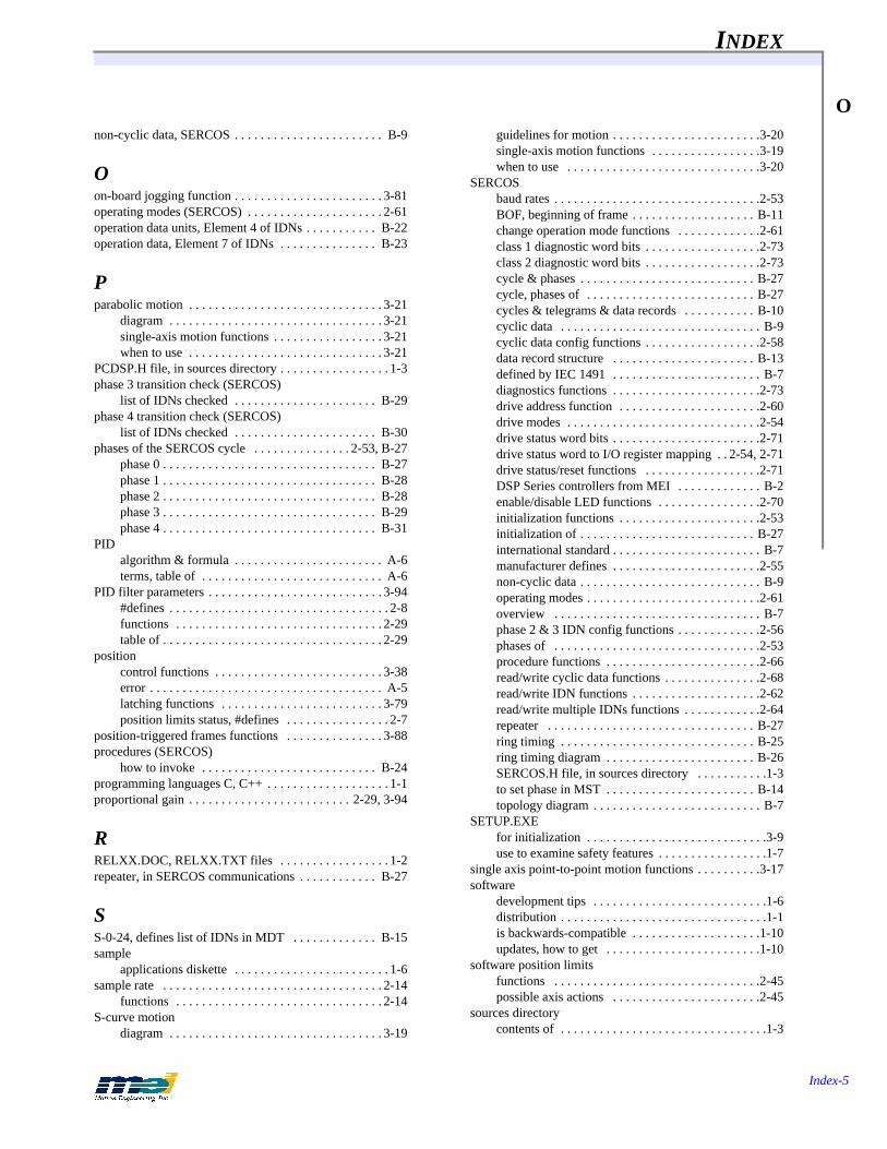
INDEX
Index-5
Onon-cyclic data, SERCOS . . . . . . . . . . . . . . . . . . . . . . . B-9
Oon-board jogging function . . . . . . . . . . . . . . . . . . . . . . . 3-81operating modes (SERCOS) . . . . . . . . . . . . . . . . . . . . . 2-61operation data units, Element 4 of IDNs . . . . . . . . . . . B-22operation data, Element 7 of IDNs . . . . . . . . . . . . . . . B-23
Pparabolic motion . . . . . . . . . . . . . . . . . . . . . . . . . . . . . . 3-21
diagram . . . . . . . . . . . . . . . . . . . . . . . . . . . . . . . . . 3-21single-axis motion functions . . . . . . . . . . . . . . . . . 3-21when to use . . . . . . . . . . . . . . . . . . . . . . . . . . . . . . 3-21
PCDSP.H file, in sources directory . . . . . . . . . . . . . . . . . 1-3phase 3 transition check (SERCOS)
list of IDNs checked . . . . . . . . . . . . . . . . . . . . . . B-29phase 4 transition check (SERCOS)
list of IDNs checked . . . . . . . . . . . . . . . . . . . . . . B-30phases of the SERCOS cycle . . . . . . . . . . . . . . . 2-53, B-27
phase 0 . . . . . . . . . . . . . . . . . . . . . . . . . . . . . . . . . B-27phase 1 . . . . . . . . . . . . . . . . . . . . . . . . . . . . . . . . . B-28phase 2 . . . . . . . . . . . . . . . . . . . . . . . . . . . . . . . . . B-28phase 3 . . . . . . . . . . . . . . . . . . . . . . . . . . . . . . . . . B-29phase 4 . . . . . . . . . . . . . . . . . . . . . . . . . . . . . . . . . B-31
PIDalgorithm & formula . . . . . . . . . . . . . . . . . . . . . . . A-6terms, table of . . . . . . . . . . . . . . . . . . . . . . . . . . . . A-6
PID filter parameters . . . . . . . . . . . . . . . . . . . . . . . . . . . 3-94#defines . . . . . . . . . . . . . . . . . . . . . . . . . . . . . . . . . . 2-8functions . . . . . . . . . . . . . . . . . . . . . . . . . . . . . . . . 2-29table of . . . . . . . . . . . . . . . . . . . . . . . . . . . . . . . . . . 2-29
positioncontrol functions . . . . . . . . . . . . . . . . . . . . . . . . . . 3-38error . . . . . . . . . . . . . . . . . . . . . . . . . . . . . . . . . . . . A-5latching functions . . . . . . . . . . . . . . . . . . . . . . . . . 3-79position limits status, #defines . . . . . . . . . . . . . . . . 2-7
position-triggered frames functions . . . . . . . . . . . . . . . 3-88procedures (SERCOS)
how to invoke . . . . . . . . . . . . . . . . . . . . . . . . . . . B-24programming languages C, C++ . . . . . . . . . . . . . . . . . . . 1-1proportional gain . . . . . . . . . . . . . . . . . . . . . . . . . 2-29, 3-94
RRELXX.DOC, RELXX.TXT files . . . . . . . . . . . . . . . . . 1-2repeater, in SERCOS communications . . . . . . . . . . . . B-27
SS-0-24, defines list of IDNs in MDT . . . . . . . . . . . . . B-15sample
applications diskette . . . . . . . . . . . . . . . . . . . . . . . . 1-6sample rate . . . . . . . . . . . . . . . . . . . . . . . . . . . . . . . . . . 2-14
functions . . . . . . . . . . . . . . . . . . . . . . . . . . . . . . . . 2-14S-curve motion
diagram . . . . . . . . . . . . . . . . . . . . . . . . . . . . . . . . . 3-19
guidelines for motion . . . . . . . . . . . . . . . . . . . . . . .3-20single-axis motion functions . . . . . . . . . . . . . . . . .3-19when to use . . . . . . . . . . . . . . . . . . . . . . . . . . . . . .3-20
SERCOSbaud rates . . . . . . . . . . . . . . . . . . . . . . . . . . . . . . . .2-53BOF, beginning of frame . . . . . . . . . . . . . . . . . . . B-11change operation mode functions . . . . . . . . . . . . .2-61class 1 diagnostic word bits . . . . . . . . . . . . . . . . . .2-73class 2 diagnostic word bits . . . . . . . . . . . . . . . . . .2-73cycle & phases . . . . . . . . . . . . . . . . . . . . . . . . . . . B-27cycle, phases of . . . . . . . . . . . . . . . . . . . . . . . . . . B-27cycles & telegrams & data records . . . . . . . . . . . B-10cyclic data . . . . . . . . . . . . . . . . . . . . . . . . . . . . . . . B-9cyclic data config functions . . . . . . . . . . . . . . . . . .2-58data record structure . . . . . . . . . . . . . . . . . . . . . . B-13defined by IEC 1491 . . . . . . . . . . . . . . . . . . . . . . . B-7diagnostics functions . . . . . . . . . . . . . . . . . . . . . . .2-73drive address function . . . . . . . . . . . . . . . . . . . . . .2-60drive modes . . . . . . . . . . . . . . . . . . . . . . . . . . . . . .2-54drive status word bits . . . . . . . . . . . . . . . . . . . . . . .2-71drive status word to I/O register mapping . . 2-54, 2-71drive status/reset functions . . . . . . . . . . . . . . . . . .2-71DSP Series controllers from MEI . . . . . . . . . . . . . B-2enable/disable LED functions . . . . . . . . . . . . . . . .2-70initialization functions . . . . . . . . . . . . . . . . . . . . . .2-53initialization of . . . . . . . . . . . . . . . . . . . . . . . . . . . B-27international standard . . . . . . . . . . . . . . . . . . . . . . . B-7manufacturer defines . . . . . . . . . . . . . . . . . . . . . . .2-55non-cyclic data . . . . . . . . . . . . . . . . . . . . . . . . . . . . B-9operating modes . . . . . . . . . . . . . . . . . . . . . . . . . . .2-61overview . . . . . . . . . . . . . . . . . . . . . . . . . . . . . . . . B-7phase 2 & 3 IDN config functions . . . . . . . . . . . . .2-56phases of . . . . . . . . . . . . . . . . . . . . . . . . . . . . . . . .2-53procedure functions . . . . . . . . . . . . . . . . . . . . . . . .2-66read/write cyclic data functions . . . . . . . . . . . . . . .2-68read/write IDN functions . . . . . . . . . . . . . . . . . . . .2-62read/write multiple IDNs functions . . . . . . . . . . . .2-64repeater . . . . . . . . . . . . . . . . . . . . . . . . . . . . . . . . B-27ring timing . . . . . . . . . . . . . . . . . . . . . . . . . . . . . . B-25ring timing diagram . . . . . . . . . . . . . . . . . . . . . . . B-26SERCOS.H file, in sources directory . . . . . . . . . . .1-3to set phase in MST . . . . . . . . . . . . . . . . . . . . . . . B-14topology diagram . . . . . . . . . . . . . . . . . . . . . . . . . . B-7
SETUP.EXEfor initialization . . . . . . . . . . . . . . . . . . . . . . . . . . . .3-9use to examine safety features . . . . . . . . . . . . . . . . .1-7
single axis point-to-point motion functions . . . . . . . . . .3-17software
development tips . . . . . . . . . . . . . . . . . . . . . . . . . . .1-6distribution . . . . . . . . . . . . . . . . . . . . . . . . . . . . . . . .1-1is backwards-compatible . . . . . . . . . . . . . . . . . . . .1-10updates, how to get . . . . . . . . . . . . . . . . . . . . . . . .1-10
software position limitsfunctions . . . . . . . . . . . . . . . . . . . . . . . . . . . . . . . .2-45possible axis actions . . . . . . . . . . . . . . . . . . . . . . .2-45
sources directorycontents of . . . . . . . . . . . . . . . . . . . . . . . . . . . . . . . .1-3
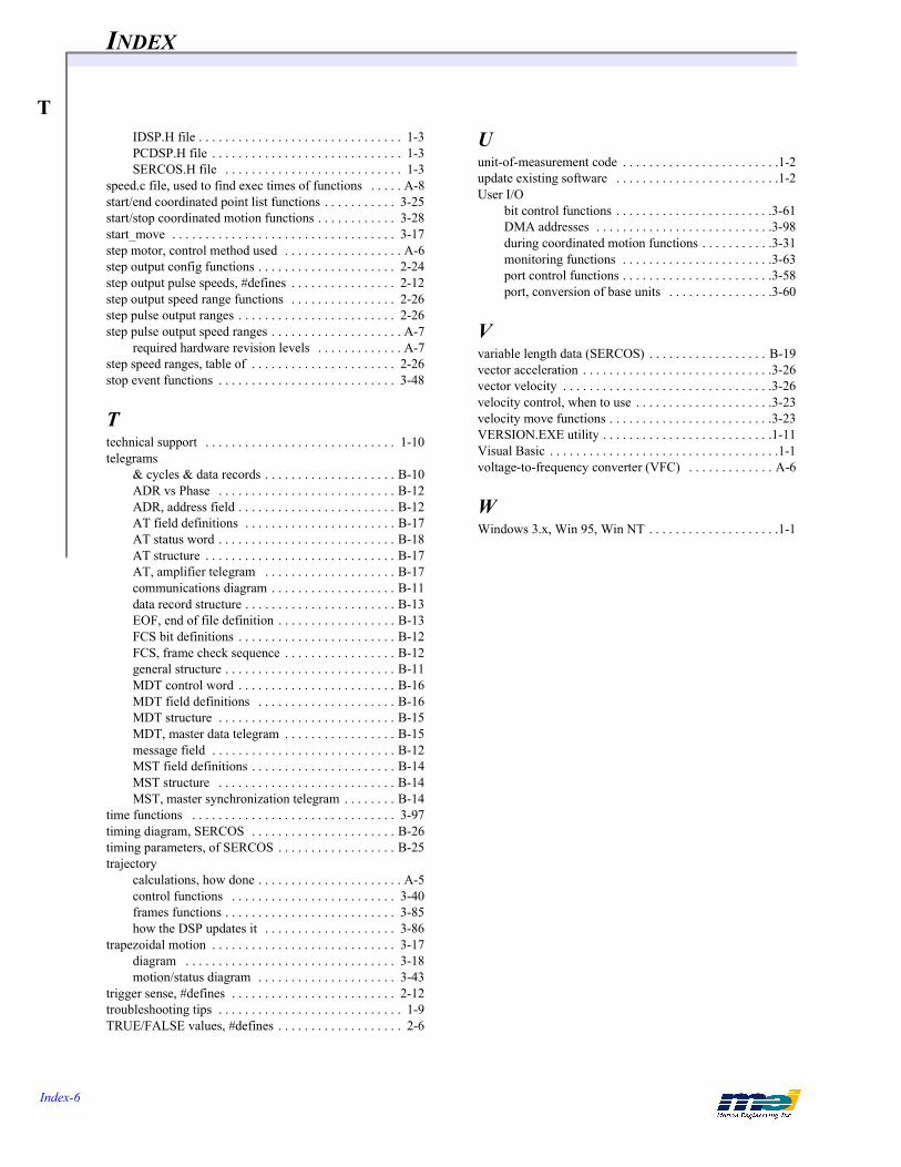
INDEX
Index-6
T
IDSP.H file . . . . . . . . . . . . . . . . . . . . . . . . . . . . . . . 1-3PCDSP.H file . . . . . . . . . . . . . . . . . . . . . . . . . . . . . 1-3SERCOS.H file . . . . . . . . . . . . . . . . . . . . . . . . . . . 1-3speed.c file, used to find exec times of functions . . . . . A-8start/end coordinated point list functions . . . . . . . . . . . 3-25start/stop coordinated motion functions . . . . . . . . . . . . 3-28start_move . . . . . . . . . . . . . . . . . . . . . . . . . . . . . . . . . . 3-17step motor, control method used . . . . . . . . . . . . . . . . . . A-6step output config functions . . . . . . . . . . . . . . . . . . . . . 2-24step output pulse speeds, #defines . . . . . . . . . . . . . . . . 2-12step output speed range functions . . . . . . . . . . . . . . . . 2-26step pulse output ranges . . . . . . . . . . . . . . . . . . . . . . . . 2-26step pulse output speed ranges . . . . . . . . . . . . . . . . . . . . A-7
required hardware revision levels . . . . . . . . . . . . . A-7step speed ranges, table of . . . . . . . . . . . . . . . . . . . . . . 2-26stop event functions . . . . . . . . . . . . . . . . . . . . . . . . . . . 3-48
Ttechnical support . . . . . . . . . . . . . . . . . . . . . . . . . . . . . 1-10telegrams
& cycles & data records . . . . . . . . . . . . . . . . . . . . B-10ADR vs Phase . . . . . . . . . . . . . . . . . . . . . . . . . . . B-12ADR, address field . . . . . . . . . . . . . . . . . . . . . . . . B-12AT field definitions . . . . . . . . . . . . . . . . . . . . . . . B-17AT status word . . . . . . . . . . . . . . . . . . . . . . . . . . . B-18AT structure . . . . . . . . . . . . . . . . . . . . . . . . . . . . . B-17AT, amplifier telegram . . . . . . . . . . . . . . . . . . . . B-17communications diagram . . . . . . . . . . . . . . . . . . . B-11data record structure . . . . . . . . . . . . . . . . . . . . . . . B-13EOF, end of file definition . . . . . . . . . . . . . . . . . . B-13FCS bit definitions . . . . . . . . . . . . . . . . . . . . . . . . B-12FCS, frame check sequence . . . . . . . . . . . . . . . . . B-12general structure . . . . . . . . . . . . . . . . . . . . . . . . . . B-11MDT control word . . . . . . . . . . . . . . . . . . . . . . . . B-16MDT field definitions . . . . . . . . . . . . . . . . . . . . . B-16MDT structure . . . . . . . . . . . . . . . . . . . . . . . . . . . B-15MDT, master data telegram . . . . . . . . . . . . . . . . . B-15message field . . . . . . . . . . . . . . . . . . . . . . . . . . . . B-12MST field definitions . . . . . . . . . . . . . . . . . . . . . . B-14MST structure . . . . . . . . . . . . . . . . . . . . . . . . . . . B-14MST, master synchronization telegram . . . . . . . . B-14
time functions . . . . . . . . . . . . . . . . . . . . . . . . . . . . . . . 3-97timing diagram, SERCOS . . . . . . . . . . . . . . . . . . . . . . B-26timing parameters, of SERCOS . . . . . . . . . . . . . . . . . . B-25trajectory
calculations, how done . . . . . . . . . . . . . . . . . . . . . . A-5control functions . . . . . . . . . . . . . . . . . . . . . . . . . 3-40frames functions . . . . . . . . . . . . . . . . . . . . . . . . . . 3-85how the DSP updates it . . . . . . . . . . . . . . . . . . . . 3-86
trapezoidal motion . . . . . . . . . . . . . . . . . . . . . . . . . . . . 3-17diagram . . . . . . . . . . . . . . . . . . . . . . . . . . . . . . . . 3-18motion/status diagram . . . . . . . . . . . . . . . . . . . . . 3-43
trigger sense, #defines . . . . . . . . . . . . . . . . . . . . . . . . . 2-12troubleshooting tips . . . . . . . . . . . . . . . . . . . . . . . . . . . . 1-9TRUE/FALSE values, #defines . . . . . . . . . . . . . . . . . . . 2-6
Uunit-of-measurement code . . . . . . . . . . . . . . . . . . . . . . . .1-2update existing software . . . . . . . . . . . . . . . . . . . . . . . . .1-2User I/O
bit control functions . . . . . . . . . . . . . . . . . . . . . . . .3-61DMA addresses . . . . . . . . . . . . . . . . . . . . . . . . . . .3-98during coordinated motion functions . . . . . . . . . . .3-31monitoring functions . . . . . . . . . . . . . . . . . . . . . . .3-63port control functions . . . . . . . . . . . . . . . . . . . . . . .3-58port, conversion of base units . . . . . . . . . . . . . . . .3-60
Vvariable length data (SERCOS) . . . . . . . . . . . . . . . . . . B-19vector acceleration . . . . . . . . . . . . . . . . . . . . . . . . . . . . .3-26vector velocity . . . . . . . . . . . . . . . . . . . . . . . . . . . . . . . .3-26velocity control, when to use . . . . . . . . . . . . . . . . . . . . .3-23velocity move functions . . . . . . . . . . . . . . . . . . . . . . . . .3-23VERSION.EXE utility . . . . . . . . . . . . . . . . . . . . . . . . . .1-11Visual Basic . . . . . . . . . . . . . . . . . . . . . . . . . . . . . . . . . . .1-1voltage-to-frequency converter (VFC) . . . . . . . . . . . . . A-6
WWindows 3.x, Win 95, Win NT . . . . . . . . . . . . . . . . . . . .1-1
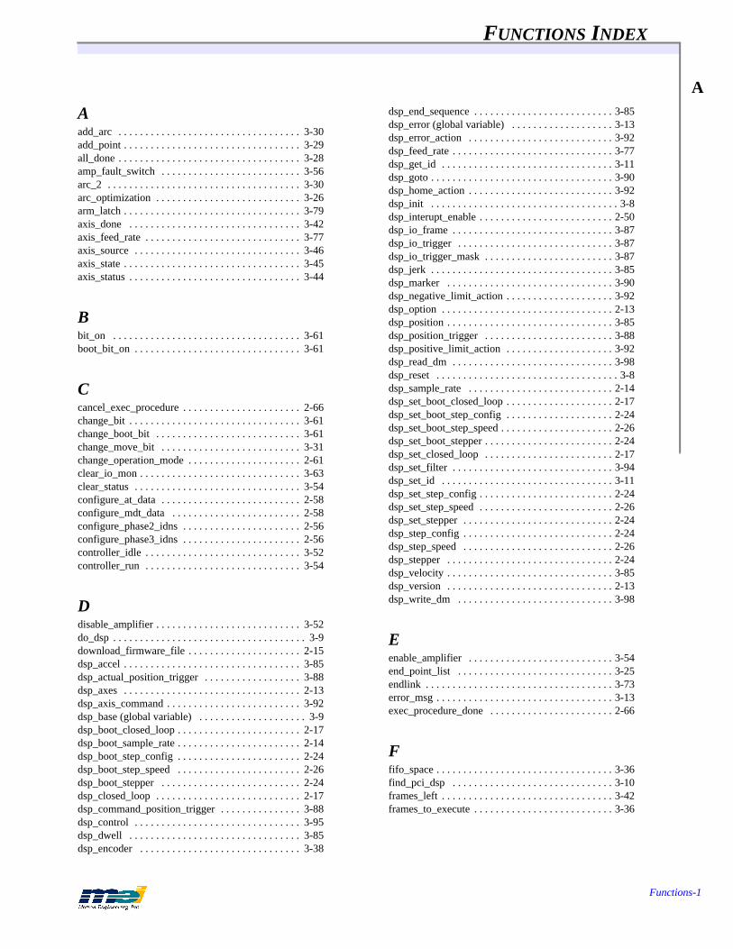
FUNCTIONS INDEX
Functions-1
A
Aadd_arc . . . . . . . . . . . . . . . . . . . . . . . . . . . . . . . . . . 3-30add_point . . . . . . . . . . . . . . . . . . . . . . . . . . . . . . . . . 3-29all_done . . . . . . . . . . . . . . . . . . . . . . . . . . . . . . . . . . 3-28amp_fault_switch . . . . . . . . . . . . . . . . . . . . . . . . . . 3-56arc_2 . . . . . . . . . . . . . . . . . . . . . . . . . . . . . . . . . . . . 3-30arc_optimization . . . . . . . . . . . . . . . . . . . . . . . . . . . 3-26arm_latch . . . . . . . . . . . . . . . . . . . . . . . . . . . . . . . . . 3-79axis_done . . . . . . . . . . . . . . . . . . . . . . . . . . . . . . . . 3-42axis_feed_rate . . . . . . . . . . . . . . . . . . . . . . . . . . . . . 3-77axis_source . . . . . . . . . . . . . . . . . . . . . . . . . . . . . . . 3-46axis_state . . . . . . . . . . . . . . . . . . . . . . . . . . . . . . . . . 3-45axis_status . . . . . . . . . . . . . . . . . . . . . . . . . . . . . . . . 3-44
Bbit_on . . . . . . . . . . . . . . . . . . . . . . . . . . . . . . . . . . . 3-61boot_bit_on . . . . . . . . . . . . . . . . . . . . . . . . . . . . . . . 3-61
Ccancel_exec_procedure . . . . . . . . . . . . . . . . . . . . . . 2-66change_bit . . . . . . . . . . . . . . . . . . . . . . . . . . . . . . . . 3-61change_boot_bit . . . . . . . . . . . . . . . . . . . . . . . . . . . 3-61change_move_bit . . . . . . . . . . . . . . . . . . . . . . . . . . 3-31change_operation_mode . . . . . . . . . . . . . . . . . . . . . 2-61clear_io_mon . . . . . . . . . . . . . . . . . . . . . . . . . . . . . . 3-63clear_status . . . . . . . . . . . . . . . . . . . . . . . . . . . . . . . 3-54configure_at_data . . . . . . . . . . . . . . . . . . . . . . . . . . 2-58configure_mdt_data . . . . . . . . . . . . . . . . . . . . . . . . 2-58configure_phase2_idns . . . . . . . . . . . . . . . . . . . . . . 2-56configure_phase3_idns . . . . . . . . . . . . . . . . . . . . . . 2-56controller_idle . . . . . . . . . . . . . . . . . . . . . . . . . . . . . 3-52controller_run . . . . . . . . . . . . . . . . . . . . . . . . . . . . . 3-54
Ddisable_amplifier . . . . . . . . . . . . . . . . . . . . . . . . . . . 3-52do_dsp . . . . . . . . . . . . . . . . . . . . . . . . . . . . . . . . . . . . 3-9download_firmware_file . . . . . . . . . . . . . . . . . . . . . 2-15dsp_accel . . . . . . . . . . . . . . . . . . . . . . . . . . . . . . . . . 3-85dsp_actual_position_trigger . . . . . . . . . . . . . . . . . . 3-88dsp_axes . . . . . . . . . . . . . . . . . . . . . . . . . . . . . . . . . 2-13dsp_axis_command . . . . . . . . . . . . . . . . . . . . . . . . . 3-92dsp_base (global variable) . . . . . . . . . . . . . . . . . . . . 3-9dsp_boot_closed_loop . . . . . . . . . . . . . . . . . . . . . . . 2-17dsp_boot_sample_rate . . . . . . . . . . . . . . . . . . . . . . . 2-14dsp_boot_step_config . . . . . . . . . . . . . . . . . . . . . . . 2-24dsp_boot_step_speed . . . . . . . . . . . . . . . . . . . . . . . 2-26dsp_boot_stepper . . . . . . . . . . . . . . . . . . . . . . . . . . 2-24dsp_closed_loop . . . . . . . . . . . . . . . . . . . . . . . . . . . 2-17dsp_command_position_trigger . . . . . . . . . . . . . . . 3-88dsp_control . . . . . . . . . . . . . . . . . . . . . . . . . . . . . . . 3-95dsp_dwell . . . . . . . . . . . . . . . . . . . . . . . . . . . . . . . . 3-85dsp_encoder . . . . . . . . . . . . . . . . . . . . . . . . . . . . . . 3-38
dsp_end_sequence . . . . . . . . . . . . . . . . . . . . . . . . . . 3-85dsp_error (global variable) . . . . . . . . . . . . . . . . . . . 3-13dsp_error_action . . . . . . . . . . . . . . . . . . . . . . . . . . . 3-92dsp_feed_rate . . . . . . . . . . . . . . . . . . . . . . . . . . . . . . 3-77dsp_get_id . . . . . . . . . . . . . . . . . . . . . . . . . . . . . . . . 3-11dsp_goto . . . . . . . . . . . . . . . . . . . . . . . . . . . . . . . . . . 3-90dsp_home_action . . . . . . . . . . . . . . . . . . . . . . . . . . . 3-92dsp_init . . . . . . . . . . . . . . . . . . . . . . . . . . . . . . . . . . . 3-8dsp_interupt_enable . . . . . . . . . . . . . . . . . . . . . . . . . 2-50dsp_io_frame . . . . . . . . . . . . . . . . . . . . . . . . . . . . . . 3-87dsp_io_trigger . . . . . . . . . . . . . . . . . . . . . . . . . . . . . 3-87dsp_io_trigger_mask . . . . . . . . . . . . . . . . . . . . . . . . 3-87dsp_jerk . . . . . . . . . . . . . . . . . . . . . . . . . . . . . . . . . . 3-85dsp_marker . . . . . . . . . . . . . . . . . . . . . . . . . . . . . . . 3-90dsp_negative_limit_action . . . . . . . . . . . . . . . . . . . . 3-92dsp_option . . . . . . . . . . . . . . . . . . . . . . . . . . . . . . . . 2-13dsp_position . . . . . . . . . . . . . . . . . . . . . . . . . . . . . . . 3-85dsp_position_trigger . . . . . . . . . . . . . . . . . . . . . . . . 3-88dsp_positive_limit_action . . . . . . . . . . . . . . . . . . . . 3-92dsp_read_dm . . . . . . . . . . . . . . . . . . . . . . . . . . . . . . 3-98dsp_reset . . . . . . . . . . . . . . . . . . . . . . . . . . . . . . . . . . 3-8dsp_sample_rate . . . . . . . . . . . . . . . . . . . . . . . . . . . 2-14dsp_set_boot_closed_loop . . . . . . . . . . . . . . . . . . . . 2-17dsp_set_boot_step_config . . . . . . . . . . . . . . . . . . . . 2-24dsp_set_boot_step_speed . . . . . . . . . . . . . . . . . . . . . 2-26dsp_set_boot_stepper . . . . . . . . . . . . . . . . . . . . . . . . 2-24dsp_set_closed_loop . . . . . . . . . . . . . . . . . . . . . . . . 2-17dsp_set_filter . . . . . . . . . . . . . . . . . . . . . . . . . . . . . . 3-94dsp_set_id . . . . . . . . . . . . . . . . . . . . . . . . . . . . . . . . 3-11dsp_set_step_config . . . . . . . . . . . . . . . . . . . . . . . . . 2-24dsp_set_step_speed . . . . . . . . . . . . . . . . . . . . . . . . . 2-26dsp_set_stepper . . . . . . . . . . . . . . . . . . . . . . . . . . . . 2-24dsp_step_config . . . . . . . . . . . . . . . . . . . . . . . . . . . . 2-24dsp_step_speed . . . . . . . . . . . . . . . . . . . . . . . . . . . . 2-26dsp_stepper . . . . . . . . . . . . . . . . . . . . . . . . . . . . . . . 2-24dsp_velocity . . . . . . . . . . . . . . . . . . . . . . . . . . . . . . . 3-85dsp_version . . . . . . . . . . . . . . . . . . . . . . . . . . . . . . . 2-13dsp_write_dm . . . . . . . . . . . . . . . . . . . . . . . . . . . . . 3-98
Eenable_amplifier . . . . . . . . . . . . . . . . . . . . . . . . . . . 3-54end_point_list . . . . . . . . . . . . . . . . . . . . . . . . . . . . . 3-25endlink . . . . . . . . . . . . . . . . . . . . . . . . . . . . . . . . . . . 3-73error_msg . . . . . . . . . . . . . . . . . . . . . . . . . . . . . . . . . 3-13exec_procedure_done . . . . . . . . . . . . . . . . . . . . . . . 2-66
Ffifo_space . . . . . . . . . . . . . . . . . . . . . . . . . . . . . . . . . 3-36find_pci_dsp . . . . . . . . . . . . . . . . . . . . . . . . . . . . . . 3-10frames_left . . . . . . . . . . . . . . . . . . . . . . . . . . . . . . . . 3-42frames_to_execute . . . . . . . . . . . . . . . . . . . . . . . . . . 3-36

FUNCTIONS INDEX
Functions-2
G
Gget_accel . . . . . . . . . . . . . . . . . . . . . . . . . . . . . . . . . 3-40get_amp_enable . . . . . . . . . . . . . . . . . . . . . . . . . . . . 2-43get_amp_enable_level . . . . . . . . . . . . . . . . . . . . . . . 2-43get_amp_fault . . . . . . . . . . . . . . . . . . . . . . . . . . . . . 2-41get_amp_fault_level . . . . . . . . . . . . . . . . . . . . . . . . . 2-41get_analog . . . . . . . . . . . . . . . . . . . . . . . . . . . . . . . . 3-65get_analog_channel . . . . . . . . . . . . . . . . . . . . . . . . . 3-67get_aux_filter . . . . . . . . . . . . . . . . . . . . . . . . . . . . . . 2-31get_axis . . . . . . . . . . . . . . . . . . . . . . . . . . . . . . . . . . 2-13get_axis_analog . . . . . . . . . . . . . . . . . . . . . . . . . . . . 3-67get_boot_amp_enable . . . . . . . . . . . . . . . . . . . . . . . 2-43get_boot_amp_enable_level . . . . . . . . . . . . . . . . . . 2-43get_boot_amp_fault . . . . . . . . . . . . . . . . . . . . . . . . . 2-41get_boot_amp_fault_level . . . . . . . . . . . . . . . . . . . . 2-41get_boot_analog_channel . . . . . . . . . . . . . . . . . . . . 3-67get_boot_aux_filter . . . . . . . . . . . . . . . . . . . . . . . . . 2-31get_boot_axis . . . . . . . . . . . . . . . . . . . . . . . . . . . . . . 2-13get_boot_dac_channel . . . . . . . . . . . . . . . . . . . . . . . 3-69get_boot_dual_loop . . . . . . . . . . . . . . . . . . . . . . . . . 2-20get_boot_e_stop_rate . . . . . . . . . . . . . . . . . . . . . . . . 3-50get_boot_error_limit . . . . . . . . . . . . . . . . . . . . . . . . 2-48get_boot_feedback . . . . . . . . . . . . . . . . . . . . . . . . . . 2-18get_boot_filter . . . . . . . . . . . . . . . . . . . . . . . . . . . . . 2-29get_boot_home . . . . . . . . . . . . . . . . . . . . . . . . . . . . . 2-32get_boot_home_index_config . . . . . . . . . . . . . . . . . 2-34get_boot_home_level . . . . . . . . . . . . . . . . . . . . . . . . 2-34get_boot_in_position . . . . . . . . . . . . . . . . . . . . . . . . 2-47get_boot_integration . . . . . . . . . . . . . . . . . . . . . . . . 2-29get_boot_io . . . . . . . . . . . . . . . . . . . . . . . . . . . . . . . 3-58get_boot_negative_level . . . . . . . . . . . . . . . . . . . . . 2-39get_boot_negative_limit . . . . . . . . . . . . . . . . . . . . . 2-37get_boot_negative_sw_limit . . . . . . . . . . . . . . . . . . 2-45get_boot_positive_level . . . . . . . . . . . . . . . . . . . . . . 2-39get_boot_positive_limit . . . . . . . . . . . . . . . . . . . . . . 2-37get_boot_positive_sw_limit . . . . . . . . . . . . . . . . . . . 2-45get_boot_stop_rate . . . . . . . . . . . . . . . . . . . . . . . . . . 3-48get_class_1_diag . . . . . . . . . . . . . . . . . . . . . . . . . . . 2-73get_class_2_diag . . . . . . . . . . . . . . . . . . . . . . . . . . . 2-73get_command . . . . . . . . . . . . . . . . . . . . . . . . . . . . . . 3-38get_dac_channel . . . . . . . . . . . . . . . . . . . . . . . . . . . . 3-69get_dac_output . . . . . . . . . . . . . . . . . . . . . . . . . . . . . 3-69get_drive_address . . . . . . . . . . . . . . . . . . . . . . . . . . 2-60get_drive_status . . . . . . . . . . . . . . . . . . . . . . . . . . . . 2-71get_dsp_time . . . . . . . . . . . . . . . . . . . . . . . . . . . . . . 3-97get_dual_loop . . . . . . . . . . . . . . . . . . . . . . . . . . . . . . 2-20get_e_stop_rate . . . . . . . . . . . . . . . . . . . . . . . . . . . . 3-50get_error . . . . . . . . . . . . . . . . . . . . . . . . . . . . . . . . . . 3-38get_error_limit . . . . . . . . . . . . . . . . . . . . . . . . . . . . . 2-48get_feedback . . . . . . . . . . . . . . . . . . . . . . . . . . . . . . 2-18get_feedback_check . . . . . . . . . . . . . . . . . . . . . . . . . 2-22get_filter . . . . . . . . . . . . . . . . . . . . . . . . . . . . . . . . . . 2-29get_frame_time . . . . . . . . . . . . . . . . . . . . . . . . . . . . 3-97get_home . . . . . . . . . . . . . . . . . . . . . . . . . . . . . . . . . 2-32get_home_index_config . . . . . . . . . . . . . . . . . . . . . . 2-34get_home_level . . . . . . . . . . . . . . . . . . . . . . . . . . . . 2-34
get_idn . . . . . . . . . . . . . . . . . . . . . . . . . . . . . . . . . . . 2-62get_idn_attributes . . . . . . . . . . . . . . . . . . . . . . . . . . 2-62get_idn_size . . . . . . . . . . . . . . . . . . . . . . . . . . . . . . . 2-62get_idn_string . . . . . . . . . . . . . . . . . . . . . . . . . . . . . 2-62get_idns . . . . . . . . . . . . . . . . . . . . . . . . . . . . . . . . . . 2-64get_in_position . . . . . . . . . . . . . . . . . . . . . . . . . . . . 2-47get_integration . . . . . . . . . . . . . . . . . . . . . . . . . . . . . 2-29get_io . . . . . . . . . . . . . . . . . . . . . . . . . . . . . . . . . . . . 3-58get_jerk . . . . . . . . . . . . . . . . . . . . . . . . . . . . . . . . . . 3-40get_last_command . . . . . . . . . . . . . . . . . . . . . . . . . . 3-38get_last_point . . . . . . . . . . . . . . . . . . . . . . . . . . . . . . 3-25get_latched_position . . . . . . . . . . . . . . . . . . . . . . . . 3-79get_negative_level . . . . . . . . . . . . . . . . . . . . . . . . . . 2-39get_negative_limit . . . . . . . . . . . . . . . . . . . . . . . . . . 2-37get_negative_sw_limit . . . . . . . . . . . . . . . . . . . . . . . 2-45get_position . . . . . . . . . . . . . . . . . . . . . . . . . . . . . . . 3-38get_positive_level . . . . . . . . . . . . . . . . . . . . . . . . . . 2-39get_positive_limit . . . . . . . . . . . . . . . . . . . . . . . . . . 2-37get_positive_sw_limit . . . . . . . . . . . . . . . . . . . . . . . 2-45get_sercos_phase . . . . . . . . . . . . . . . . . . . . . . . . . . . 2-53get_stop_rate . . . . . . . . . . . . . . . . . . . . . . . . . . . . . . 3-48get_timer . . . . . . . . . . . . . . . . . . . . . . . . . . . . . . . . . 3-71get_velocity . . . . . . . . . . . . . . . . . . . . . . . . . . . . . . . 3-40
Hhome_switch . . . . . . . . . . . . . . . . . . . . . . . . . . . . . . 3-56
Iin_motion . . . . . . . . . . . . . . . . . . . . . . . . . . . . . . . . . 3-42in_position . . . . . . . . . . . . . . . . . . . . . . . . . . . . . . . . 3-42in_sequence . . . . . . . . . . . . . . . . . . . . . . . . . . . . . . . 3-42init_analog . . . . . . . . . . . . . . . . . . . . . . . . . . . . . . . . 3-65init_boot_io . . . . . . . . . . . . . . . . . . . . . . . . . . . . . . . 3-58init_io . . . . . . . . . . . . . . . . . . . . . . . . . . . . . . . . . . . . 3-58init_timer . . . . . . . . . . . . . . . . . . . . . . . . . . . . . . . . . 3-71interrupt_on_event . . . . . . . . . . . . . . . . . . . . . . . . . . 2-50io_changed . . . . . . . . . . . . . . . . . . . . . . . . . . . . . . . . 3-63io_mon . . . . . . . . . . . . . . . . . . . . . . . . . . . . . . . . . . . 3-63is_boot_unipolar . . . . . . . . . . . . . . . . . . . . . . . . . . . 2-28is_unipolar . . . . . . . . . . . . . . . . . . . . . . . . . . . . . . . . 2-28
Jjog_axis . . . . . . . . . . . . . . . . . . . . . . . . . . . . . . . . . . 3-81
Llatch . . . . . . . . . . . . . . . . . . . . . . . . . . . . . . . . . . . . . 3-79latch_status . . . . . . . . . . . . . . . . . . . . . . . . . . . . . . . 3-79load_spline_motion . . . . . . . . . . . . . . . . . . . . . . . . . 3-33
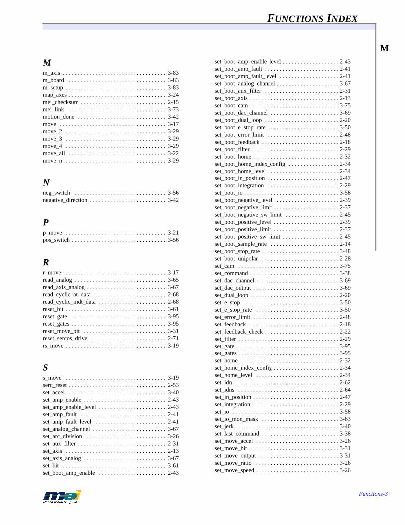
FUNCTIONS INDEX
Functions-3
M
Mm_axis . . . . . . . . . . . . . . . . . . . . . . . . . . . . . . . . . . . 3-83m_board . . . . . . . . . . . . . . . . . . . . . . . . . . . . . . . . . 3-83m_setup . . . . . . . . . . . . . . . . . . . . . . . . . . . . . . . . . . 3-83map_axes . . . . . . . . . . . . . . . . . . . . . . . . . . . . . . . . . 3-24mei_checksum . . . . . . . . . . . . . . . . . . . . . . . . . . . . . 2-15mei_link . . . . . . . . . . . . . . . . . . . . . . . . . . . . . . . . . 3-73motion_done . . . . . . . . . . . . . . . . . . . . . . . . . . . . . . 3-42move . . . . . . . . . . . . . . . . . . . . . . . . . . . . . . . . . . . . 3-17move_2 . . . . . . . . . . . . . . . . . . . . . . . . . . . . . . . . . . 3-29move_3 . . . . . . . . . . . . . . . . . . . . . . . . . . . . . . . . . . 3-29move_4 . . . . . . . . . . . . . . . . . . . . . . . . . . . . . . . . . . 3-29move_all . . . . . . . . . . . . . . . . . . . . . . . . . . . . . . . . . 3-22move_n . . . . . . . . . . . . . . . . . . . . . . . . . . . . . . . . . . 3-29
Nneg_switch . . . . . . . . . . . . . . . . . . . . . . . . . . . . . . . 3-56negative_direction . . . . . . . . . . . . . . . . . . . . . . . . . . 3-42
Pp_move . . . . . . . . . . . . . . . . . . . . . . . . . . . . . . . . . . 3-21pos_switch . . . . . . . . . . . . . . . . . . . . . . . . . . . . . . . . 3-56
Rr_move . . . . . . . . . . . . . . . . . . . . . . . . . . . . . . . . . . 3-17read_analog . . . . . . . . . . . . . . . . . . . . . . . . . . . . . . . 3-65read_axis_analog . . . . . . . . . . . . . . . . . . . . . . . . . . . 3-67read_cyclic_at_data . . . . . . . . . . . . . . . . . . . . . . . . . 2-68read_cyclic_mdt_data . . . . . . . . . . . . . . . . . . . . . . . 2-68reset_bit . . . . . . . . . . . . . . . . . . . . . . . . . . . . . . . . . . 3-61reset_gate . . . . . . . . . . . . . . . . . . . . . . . . . . . . . . . . 3-95reset_gates . . . . . . . . . . . . . . . . . . . . . . . . . . . . . . . . 3-95reset_move_bit . . . . . . . . . . . . . . . . . . . . . . . . . . . . 3-31reset_sercos_drive . . . . . . . . . . . . . . . . . . . . . . . . . . 2-71rs_move . . . . . . . . . . . . . . . . . . . . . . . . . . . . . . . . . . 3-19
Ss_move . . . . . . . . . . . . . . . . . . . . . . . . . . . . . . . . . . 3-19serc_reset . . . . . . . . . . . . . . . . . . . . . . . . . . . . . . . . . 2-53set_accel . . . . . . . . . . . . . . . . . . . . . . . . . . . . . . . . . 3-40set_amp_enable . . . . . . . . . . . . . . . . . . . . . . . . . . . . 2-43set_amp_enable_level . . . . . . . . . . . . . . . . . . . . . . . 2-43set_amp_fault . . . . . . . . . . . . . . . . . . . . . . . . . . . . . 2-41set_amp_fault_level . . . . . . . . . . . . . . . . . . . . . . . . 2-41set_analog_channel . . . . . . . . . . . . . . . . . . . . . . . . . 3-67set_arc_division . . . . . . . . . . . . . . . . . . . . . . . . . . . 3-26set_aux_filter . . . . . . . . . . . . . . . . . . . . . . . . . . . . . . 2-31set_axis . . . . . . . . . . . . . . . . . . . . . . . . . . . . . . . . . . 2-13set_axis_analog . . . . . . . . . . . . . . . . . . . . . . . . . . . . 3-67set_bit . . . . . . . . . . . . . . . . . . . . . . . . . . . . . . . . . . . 3-61set_boot_amp_enable . . . . . . . . . . . . . . . . . . . . . . . 2-43
set_boot_amp_enable_level . . . . . . . . . . . . . . . . . . . 2-43set_boot_amp_fault . . . . . . . . . . . . . . . . . . . . . . . . . 2-41set_boot_amp_fault_level . . . . . . . . . . . . . . . . . . . . 2-41set_boot_analog_channel . . . . . . . . . . . . . . . . . . . . . 3-67set_boot_aux_filter . . . . . . . . . . . . . . . . . . . . . . . . . 2-31set_boot_axis . . . . . . . . . . . . . . . . . . . . . . . . . . . . . . 2-13set_boot_cam . . . . . . . . . . . . . . . . . . . . . . . . . . . . . . 3-75set_boot_dac_channel . . . . . . . . . . . . . . . . . . . . . . . 3-69set_boot_dual_loop . . . . . . . . . . . . . . . . . . . . . . . . . 2-20set_boot_e_stop_rate . . . . . . . . . . . . . . . . . . . . . . . . 3-50set_boot_error_limit . . . . . . . . . . . . . . . . . . . . . . . . 2-48set_boot_feedback . . . . . . . . . . . . . . . . . . . . . . . . . . 2-18set_boot_filter . . . . . . . . . . . . . . . . . . . . . . . . . . . . . 2-29set_boot_home . . . . . . . . . . . . . . . . . . . . . . . . . . . . . 2-32set_boot_home_index_config . . . . . . . . . . . . . . . . . 2-34set_boot_home_level . . . . . . . . . . . . . . . . . . . . . . . . 2-34set_boot_in_position . . . . . . . . . . . . . . . . . . . . . . . . 2-47set_boot_integration . . . . . . . . . . . . . . . . . . . . . . . . 2-29set_boot_io . . . . . . . . . . . . . . . . . . . . . . . . . . . . . . . . 3-58set_boot_negative_level . . . . . . . . . . . . . . . . . . . . . 2-39set_boot_negative_limit . . . . . . . . . . . . . . . . . . . . . . 2-37set_boot_negative_sw_limit . . . . . . . . . . . . . . . . . . 2-45set_boot_positive_level . . . . . . . . . . . . . . . . . . . . . . 2-39set_boot_positive_limit . . . . . . . . . . . . . . . . . . . . . . 2-37set_boot_positive_sw_limit . . . . . . . . . . . . . . . . . . . 2-45set_boot_sample_rate . . . . . . . . . . . . . . . . . . . . . . . 2-14set_boot_stop_rate . . . . . . . . . . . . . . . . . . . . . . . . . . 3-48set_boot_unipolar . . . . . . . . . . . . . . . . . . . . . . . . . . 2-28set_cam . . . . . . . . . . . . . . . . . . . . . . . . . . . . . . . . . . 3-75set_command . . . . . . . . . . . . . . . . . . . . . . . . . . . . . . 3-38set_dac_channel . . . . . . . . . . . . . . . . . . . . . . . . . . . . 3-69set_dac_output . . . . . . . . . . . . . . . . . . . . . . . . . . . . . 3-69set_dual_loop . . . . . . . . . . . . . . . . . . . . . . . . . . . . . . 2-20set_e_stop . . . . . . . . . . . . . . . . . . . . . . . . . . . . . . . . 3-50set_e_stop_rate . . . . . . . . . . . . . . . . . . . . . . . . . . . . 3-50set_error_limit . . . . . . . . . . . . . . . . . . . . . . . . . . . . . 2-48set_feedback . . . . . . . . . . . . . . . . . . . . . . . . . . . . . . 2-18set_feedback_check . . . . . . . . . . . . . . . . . . . . . . . . . 2-22set_filter . . . . . . . . . . . . . . . . . . . . . . . . . . . . . . . . . . 2-29set_gate . . . . . . . . . . . . . . . . . . . . . . . . . . . . . . . . . . 3-95set_gates . . . . . . . . . . . . . . . . . . . . . . . . . . . . . . . . . . 3-95set_home . . . . . . . . . . . . . . . . . . . . . . . . . . . . . . . . . 2-32set_home_index_config . . . . . . . . . . . . . . . . . . . . . . 2-34set_home_level . . . . . . . . . . . . . . . . . . . . . . . . . . . . 2-34set_idn . . . . . . . . . . . . . . . . . . . . . . . . . . . . . . . . . . . 2-62set_idns . . . . . . . . . . . . . . . . . . . . . . . . . . . . . . . . . . 2-64set_in_position . . . . . . . . . . . . . . . . . . . . . . . . . . . . . 2-47set_integration . . . . . . . . . . . . . . . . . . . . . . . . . . . . . 2-29set_io . . . . . . . . . . . . . . . . . . . . . . . . . . . . . . . . . . . . 3-58set_io_mon_mask . . . . . . . . . . . . . . . . . . . . . . . . . . 3-63set_jerk . . . . . . . . . . . . . . . . . . . . . . . . . . . . . . . . . . . 3-40set_last_command . . . . . . . . . . . . . . . . . . . . . . . . . . 3-38set_move_accel . . . . . . . . . . . . . . . . . . . . . . . . . . . . 3-26set_move_bit . . . . . . . . . . . . . . . . . . . . . . . . . . . . . . 3-31set_move_output . . . . . . . . . . . . . . . . . . . . . . . . . . . 3-31set_move_ratio . . . . . . . . . . . . . . . . . . . . . . . . . . . . . 3-26set_move_speed . . . . . . . . . . . . . . . . . . . . . . . . . . . . 3-26
FUNCTIONS INDEX
Functions-4
Tset_negative_level . . . . . . . . . . . . . . . . . . . . . . . . . . 2-39set_negative_limit . . . . . . . . . . . . . . . . . . . . . . . . . . 2-37set_negative_sw_limit . . . . . . . . . . . . . . . . . . . . . . . 2-45set_points . . . . . . . . . . . . . . . . . . . . . . . . . . . . . . . . . 3-28set_position . . . . . . . . . . . . . . . . . . . . . . . . . . . . . . . 3-38set_position()
can cause motor to jump . . . . . . . . . . . . . . . . . 3-39set_positive_level . . . . . . . . . . . . . . . . . . . . . . . . . . . 2-39set_positive_limit . . . . . . . . . . . . . . . . . . . . . . . . . . . 2-37set_positive_sw_limit . . . . . . . . . . . . . . . . . . . . . . . 2-45set_sample_rate . . . . . . . . . . . . . . . . . . . . . . . . . . . . 2-14set_stop . . . . . . . . . . . . . . . . . . . . . . . . . . . . . . . . . . 3-48set_stop_rate . . . . . . . . . . . . . . . . . . . . . . . . . . . . . . 3-48set_timer . . . . . . . . . . . . . . . . . . . . . . . . . . . . . . . . . . 3-71set_unipolar . . . . . . . . . . . . . . . . . . . . . . . . . . . . . . . 2-28set_velocity . . . . . . . . . . . . . . . . . . . . . . . . . . . . . . . 3-40sprof_move . . . . . . . . . . . . . . . . . . . . . . . . . . . . . . . 3-19start_analog . . . . . . . . . . . . . . . . . . . . . . . . . . . . . . . 3-65start_exec_procedure . . . . . . . . . . . . . . . . . . . . . . . . 2-66start_motion . . . . . . . . . . . . . . . . . . . . . . . . . . . . . . . 3-28start_move . . . . . . . . . . . . . . . . . . . . . . . . . . . . . . . . 3-17start_move_all . . . . . . . . . . . . . . . . . . . . . . . . . . . . . 3-22start_p_move . . . . . . . . . . . . . . . . . . . . . . . . . . . . . . 3-21start_point_list . . . . . . . . . . . . . . . . . . . . . . . . . . . . . 3-25start_r_move . . . . . . . . . . . . . . . . . . . . . . . . . . . . . . 3-17start_rs_move . . . . . . . . . . . . . . . . . . . . . . . . . . . . . . 3-19start_s_move . . . . . . . . . . . . . . . . . . . . . . . . . . . . . . 3-19start_spline_motion . . . . . . . . . . . . . . . . . . . . . . . . . 3-33start_sprof_move . . . . . . . . . . . . . . . . . . . . . . . . . . . 3-19start_t_move . . . . . . . . . . . . . . . . . . . . . . . . . . . . . . . 3-17stop_motion . . . . . . . . . . . . . . . . . . . . . . . . . . . . . . . 3-28
Tt_move . . . . . . . . . . . . . . . . . . . . . . . . . . . . . . . . . . . 3-17turn_off_sercos_led . . . . . . . . . . . . . . . . . . . . . . . . . 2-70turn_on_sercos_led . . . . . . . . . . . . . . . . . . . . . . . . . 2-70
Uunderstand_dsp . . . . . . . . . . . . . . . . . . . . . . . . . . . . . 3-9upload_firmware_file . . . . . . . . . . . . . . . . . . . . . . . . 2-15
Vv_move . . . . . . . . . . . . . . . . . . . . . . . . . . . . . . . . . . . 3-23
Wwait_for_all . . . . . . . . . . . . . . . . . . . . . . . . . . . . . . . 3-22wait_for_done . . . . . . . . . . . . . . . . . . . . . . . . . . . . . 3-17write_cyclic_mdt_data . . . . . . . . . . . . . . . . . . . . . . . 2-68
WHICH FUNCTION DOES THAT? INDEX
Which Function?-1
A
Aabort event
clear one on axis . . . . . . . . . . . . . . . . . . . . . . . . . . 3-54generate one . . . . . . . . . . . . . . . . . . . . . . . . . . . . . 3-52
accelerationcalculations for arcs, enable/disable optimization of 3-
26to constant velocity . . . . . . . . . . . . . . . . . . . . . . . . 3-23to set vector . . . . . . . . . . . . . . . . . . . . . . . . . . . . . . 3-26
acceleration (command)get . . . . . . . . . . . . . . . . . . . . . . . . . . . . . . . . . . . . . 3-40to set . . . . . . . . . . . . . . . . . . . . . . . . . . . . . . . . . . . 3-40
action framesdownload frame to send action to other axis . . . . 3-92download frame to set home logic action . . . . . . . 3-92download frame to set negative logic action . . . . 3-92download frame to set position error action . . . . . 3-92download frame to set positive logic action . . . . . 3-92
actual positionget . . . . . . . . . . . . . . . . . . . . . . . . . . . . . . . . . . . . . 3-38to set . . . . . . . . . . . . . . . . . . . . . . . . . . . . . . . . . . . 3-38
amp enable outputconfigure run state of . . . . . . . . . . . . . . . . . . . . . . 2-43configure run state of (boot) . . . . . . . . . . . . . . . . . 2-43disable it . . . . . . . . . . . . . . . . . . . . . . . . . . . . . . . . 3-52enable it . . . . . . . . . . . . . . . . . . . . . . . . . . . . . . . . . 3-54read run state of . . . . . . . . . . . . . . . . . . . . . . . . . . 2-43read run state of (boot) . . . . . . . . . . . . . . . . . . . . . 2-43read state of . . . . . . . . . . . . . . . . . . . . . . . . . . . . . . 2-43read state of (boot) . . . . . . . . . . . . . . . . . . . . . . . . 2-43to set the state . . . . . . . . . . . . . . . . . . . . . . . . . . . . 2-43to set the state (boot) . . . . . . . . . . . . . . . . . . . . . . . 2-43
amp fault inputconfigure active state . . . . . . . . . . . . . . . . . . . . . . 2-41configure active state (boot) . . . . . . . . . . . . . . . . . 2-41read active state . . . . . . . . . . . . . . . . . . . . . . . . . . . 2-41read active state (boot) . . . . . . . . . . . . . . . . . . . . . 2-41return state of . . . . . . . . . . . . . . . . . . . . . . . . . . . . 3-56
amp fault input actionread . . . . . . . . . . . . . . . . . . . . . . . . . . . . . . . . . . . . 2-41read (boot) . . . . . . . . . . . . . . . . . . . . . . . . . . . . . . . 2-41to set . . . . . . . . . . . . . . . . . . . . . . . . . . . . . . . . . . . 2-41to set (boot) . . . . . . . . . . . . . . . . . . . . . . . . . . . . . . 2-41
analog inputsget . . . . . . . . . . . . . . . . . . . . . . . . . . . . . . . . . . . . . 3-65initialize . . . . . . . . . . . . . . . . . . . . . . . . . . . . . . . . 3-65read input 15 msec after control word . . . . . . . . . 3-65write control word to D/A . . . . . . . . . . . . . . . . . . . 3-65
arc segment (interpolated)set length . . . . . . . . . . . . . . . . . . . . . . . . . . . . . . . . 3-26
aux digital filter coefficientsget . . . . . . . . . . . . . . . . . . . . . . . . . . . . . . . . . . . . .2-31get (boot) . . . . . . . . . . . . . . . . . . . . . . . . . . . . . . . .2-31to set . . . . . . . . . . . . . . . . . . . . . . . . . . . . . . . . . . .2-31to set (boot) . . . . . . . . . . . . . . . . . . . . . . . . . . . . . .2-31
axes (2)configure for master/cam . . . . . . . . . . . . . . . . . . . .3-75configure for master/cam (boot) . . . . . . . . . . . . . .3-75connect together with a ratio . . . . . . . . . . . . . . . . .3-73disconnect . . . . . . . . . . . . . . . . . . . . . . . . . . . . . . .3-73
axes (mapped)set resolution ratios . . . . . . . . . . . . . . . . . . . . . . . .3-26
axisconfigure for open or closed loop . . . . . . . . . . . . .2-17configure for open or closed loop (boot) . . . . . . . .2-17enable/disable . . . . . . . . . . . . . . . . . . . . . . . . . . . .2-13is the motion done yet? . . . . . . . . . . . . . . . . . . . . .3-42return current running condition . . . . . . . . . . . . . .3-44return currently executing event . . . . . . . . . . . . . .3-45return number of enabled axes . . . . . . . . . . . . . . .2-13see if configured for open or closed loop . . . . . . .2-17see if configured for open or closed loop (boot) . .2-17
axis analog inputsconfigure DSP to read . . . . . . . . . . . . . . . . . . . . . .3-67read configuration . . . . . . . . . . . . . . . . . . . . . . . . .3-67read configured analog channel . . . . . . . . . . . . . . .3-67read configured analog channel (boot) . . . . . . . . .3-67read inputs from DSP . . . . . . . . . . . . . . . . . . . . . .3-67to set analog channel . . . . . . . . . . . . . . . . . . . . . . .3-67to set boot analog channel . . . . . . . . . . . . . . . . . . .3-67
axis analog outputsconfigure boot polarity (unipolar or bipolar) . . . .2-28configure DAC channel . . . . . . . . . . . . . . . . . . . . .3-69configure DAC channel (boot) . . . . . . . . . . . . . . .3-69configure polarity (unipolar or bipolar) . . . . . . . . .2-28get value of 16-bit output . . . . . . . . . . . . . . . . . . .3-69read configured DAC channel . . . . . . . . . . . . . . . .3-69read configured DAC channel (boot) . . . . . . . . . .3-69read polarity (unipolar?) . . . . . . . . . . . . . . . . . . . .2-28read polarity for boot (unipolar?) . . . . . . . . . . . . .2-28to set value of 16-bit output . . . . . . . . . . . . . . . . . .3-69
axis config statusenable/disable (boot) . . . . . . . . . . . . . . . . . . . . . . .2-13read status (enable/disable) . . . . . . . . . . . . . . . . . .2-13read status of enable/disable (boot) . . . . . . . . . . . .2-13
axis mapconfigure for coordinated motion . . . . . . . . . . . . .3-24
axis step outputconfigure speed range of . . . . . . . . . . . . . . . . . . . .2-26configure speed range of (boot) . . . . . . . . . . . . . . .2-26enable/disable . . . . . . . . . . . . . . . . . . . . . . . . . . . .2-24enable/disable at boot . . . . . . . . . . . . . . . . . . . . . .2-24

WHICH FUNCTION DOES THAT? INDEX
Which Function?-2
Bread configuration . . . . . . . . . . . . . . . . . . . . . . . . 2-24read speed range of . . . . . . . . . . . . . . . . . . . . . . . 2-26read speed range of (boot) . . . . . . . . . . . . . . . . . . 2-26read status (enabled at boot?) . . . . . . . . . . . . . . . 2-24read status (enabled?) . . . . . . . . . . . . . . . . . . . . . 2-24return boot step configuration . . . . . . . . . . . . . . . 2-24set boot step configuration . . . . . . . . . . . . . . . . . . 2-24set step configuration . . . . . . . . . . . . . . . . . . . . . . 2-24
Bbase I/O address
to set . . . . . . . . . . . . . . . . . . . . . . . . . . . . . . . . . . . . 3-8
boot memoryupdate checksum . . . . . . . . . . . . . . . . . . . . . . . . . 2-15
Cchecksum
update it . . . . . . . . . . . . . . . . . . . . . . . . . . . . . . . . 2-15
circular arcadd 2-axis one to point list . . . . . . . . . . . . . . . . . . 3-30add 2-axis one to point list (pointer) . . . . . . . . . . 3-30
command accelerationget . . . . . . . . . . . . . . . . . . . . . . . . . . . . . . . . . . . . 3-40to set . . . . . . . . . . . . . . . . . . . . . . . . . . . . . . . . . . . 3-40
command jerkget . . . . . . . . . . . . . . . . . . . . . . . . . . . . . . . . . . . . 3-40to set . . . . . . . . . . . . . . . . . . . . . . . . . . . . . . . . . . . 3-40
command positionget current value . . . . . . . . . . . . . . . . . . . . . . . . . 3-38get last one . . . . . . . . . . . . . . . . . . . . . . . . . . . . . . 3-38set last value . . . . . . . . . . . . . . . . . . . . . . . . . . . . 3-38to set . . . . . . . . . . . . . . . . . . . . . . . . . . . . . . . . . . . 3-38
command position registerto set . . . . . . . . . . . . . . . . . . . . . . . . . . . . . . . . . . . 3-38
command velocityget . . . . . . . . . . . . . . . . . . . . . . . . . . . . . . . . . . . . 3-40is it negative? . . . . . . . . . . . . . . . . . . . . . . . . . . . . 3-42is it non-zero? . . . . . . . . . . . . . . . . . . . . . . . . . . . 3-42to set . . . . . . . . . . . . . . . . . . . . . . . . . . . . . . . . . . . 3-40
controllergenerate abort event . . . . . . . . . . . . . . . . . . . . . . . 3-52to reset to boot state . . . . . . . . . . . . . . . . . . . . . . . . 3-8to set base I/O address . . . . . . . . . . . . . . . . . . . . . . 3-8
coordinated motionconfigure axis map . . . . . . . . . . . . . . . . . . . . . . . 3-24set number of points before auto-starting . . . . . . 3-28start . . . . . . . . . . . . . . . . . . . . . . . . . . . . . . . . . . . 3-28
stop . . . . . . . . . . . . . . . . . . . . . . . . . . . . . . . . . . . .3-28verify completion of . . . . . . . . . . . . . . . . . . . . . . .3-28
counter/timerget value of . . . . . . . . . . . . . . . . . . . . . . . . . . . . . .3-71initialize it . . . . . . . . . . . . . . . . . . . . . . . . . . . . . . .3-71to set it . . . . . . . . . . . . . . . . . . . . . . . . . . . . . . . . . .3-71
cubic spline coordinated motiondownload frames for . . . . . . . . . . . . . . . . . . . . . . .3-33start . . . . . . . . . . . . . . . . . . . . . . . . . . . . . . . . . . . .3-33
DD/A
write control word to . . . . . . . . . . . . . . . . . . . . . . .3-65
DMA (DSP’s data memory)read it . . . . . . . . . . . . . . . . . . . . . . . . . . . . . . . . . . .3-98write to it . . . . . . . . . . . . . . . . . . . . . . . . . . . . . . . .3-98
DSP sample rateread boot value . . . . . . . . . . . . . . . . . . . . . . . . . . .2-14read it . . . . . . . . . . . . . . . . . . . . . . . . . . . . . . . . . . .2-14set boot value . . . . . . . . . . . . . . . . . . . . . . . . . . . . .2-14to set . . . . . . . . . . . . . . . . . . . . . . . . . . . . . . . . . . .2-14
dual loopat boot, configure axis for . . . . . . . . . . . . . . . . . . .2-20configure axis for . . . . . . . . . . . . . . . . . . . . . . . . . .2-20read if axis is configured for . . . . . . . . . . . . . . . . .2-20read if axis is configured for it at boot . . . . . . . . .2-20
Eemergency stop event
clear it . . . . . . . . . . . . . . . . . . . . . . . . . . . . . . . . . .3-54generate one on axis . . . . . . . . . . . . . . . . . . . . . . .3-50read deceleration rate . . . . . . . . . . . . . . . . . . . . . . .3-50read deceleration rate (boot) . . . . . . . . . . . . . . . . .3-50set deceleration rate . . . . . . . . . . . . . . . . . . . . . . . .3-50set deceleration rate (boot) . . . . . . . . . . . . . . . . . .3-50
encoderread 16-bit value directly . . . . . . . . . . . . . . . . . . . .3-38
encoder feedback fault detectionenable/disable . . . . . . . . . . . . . . . . . . . . . . . . . . . .2-22read status of enable/disable . . . . . . . . . . . . . . . . .2-22
environment variablesinitialize (shell) . . . . . . . . . . . . . . . . . . . . . . . . . . . .3-9read . . . . . . . . . . . . . . . . . . . . . . . . . . . . . . . . . . . . .3-9
error (last one)global variable dsp_error . . . . . . . . . . . . . . . . . . . .3-13

WHICH FUNCTION DOES THAT? INDEX
Which Function?-3
Ferror (position)
get current value . . . . . . . . . . . . . . . . . . . . . . . . . . 3-38
error messageget . . . . . . . . . . . . . . . . . . . . . . . . . . . . . . . . . . . . . 3-13
eventreturn the one that is currently executing . . . . . . . 3-45
exception eventreturn cause of . . . . . . . . . . . . . . . . . . . . . . . . . . . . 3-46
Ffeed rates
change for 1 axis . . . . . . . . . . . . . . . . . . . . . . . . . . 3-77change for all axes . . . . . . . . . . . . . . . . . . . . . . . . 3-77
feedback deviceconfigure for axis . . . . . . . . . . . . . . . . . . . . . . . . . 2-18configure for axis (boot) . . . . . . . . . . . . . . . . . . . . 2-18read what is configured for axis . . . . . . . . . . . . . . 2-18read what is configured for axis (boot) . . . . . . . . . 2-18
firmwarecopy file from boot memory to host . . . . . . . . . . . 2-15copy file from host to boot memory . . . . . . . . . . . 2-15return option number . . . . . . . . . . . . . . . . . . . . . . 2-13return version number . . . . . . . . . . . . . . . . . . . . . . 2-13update checksum . . . . . . . . . . . . . . . . . . . . . . . . . . 2-15
frame controlclear gate flag for 1 axis . . . . . . . . . . . . . . . . . . . . 3-95clear gate flag for n axes . . . . . . . . . . . . . . . . . . . . 3-95enable/disable control bits in frames to be downloaded
3-95set gate flag for 1 axis . . . . . . . . . . . . . . . . . . . . . . 3-95set gate flag for n axes . . . . . . . . . . . . . . . . . . . . . 3-95
frame sample timerreturn value of . . . . . . . . . . . . . . . . . . . . . . . . . . . . 3-97
framesany frames left to execute on axis? . . . . . . . . . . . . 3-42are they loading or executing? . . . . . . . . . . . . . . . 3-42download frame to set PID filter parameters . . . . 3-94return number of available frames in DSP buffer . 3-36return number of frames still waiting to execute . 3-36
frames (action)download frame to send action to other axis . . . . 3-92download frame to set home logic action . . . . . . . 3-92download frame to set negative logic action . . . . 3-92download frame to set position error action . . . . . 3-92download frame to set positive logic action . . . . . 3-92
Ggate flags
clear for 1 axis (frame control) . . . . . . . . . . . . . . .3-95clear for n axes (frame control) . . . . . . . . . . . . . . .3-95to set for 1 axis (frame control) . . . . . . . . . . . . . . .3-95to set for n axes (frame control) . . . . . . . . . . . . . .3-95
Hhome logic
return state of . . . . . . . . . . . . . . . . . . . . . . . . . . . . .3-56
home/index logicconfigure . . . . . . . . . . . . . . . . . . . . . . . . . . . . . . . .2-34configure (boot) . . . . . . . . . . . . . . . . . . . . . . . . . . .2-34configure active state . . . . . . . . . . . . . . . . . . . . . . .2-34configure active state (boot) . . . . . . . . . . . . . . . . .2-34read active state . . . . . . . . . . . . . . . . . . . . . . . . . . .2-34read active state (boot) . . . . . . . . . . . . . . . . . . . . .2-34read configuration . . . . . . . . . . . . . . . . . . . . . . . . .2-34read configuration (boot) . . . . . . . . . . . . . . . . . . . .2-34
home/index logic actionread . . . . . . . . . . . . . . . . . . . . . . . . . . . . . . . . . . . .2-32read (boot) . . . . . . . . . . . . . . . . . . . . . . . . . . . . . . .2-32to set . . . . . . . . . . . . . . . . . . . . . . . . . . . . . . . . . . .2-32to set (boot) . . . . . . . . . . . . . . . . . . . . . . . . . . . . . .2-32
II/O address
global variable dsp_base . . . . . . . . . . . . . . . . . . . . .3-9
I/O framesdelay execution of next frame until bit level changes to
state . . . . . . . . . . . . . . . . . . . . . . . . . . . . . . . . . .3-87delay execution of next frame until masked port
changes to state . . . . . . . . . . . . . . . . . . . . . . . . .3-87update state of 8-bit User I/O port . . . . . . . . . . . . .3-87
I/O, see User I/O.initialize
controller . . . . . . . . . . . . . . . . . . . . . . . . . . . . . . . . .3-8
in-position windowconfigure width . . . . . . . . . . . . . . . . . . . . . . . . . . .2-47configure width (boot) . . . . . . . . . . . . . . . . . . . . . .2-47read width . . . . . . . . . . . . . . . . . . . . . . . . . . . . . . .2-47read width (boot) . . . . . . . . . . . . . . . . . . . . . . . . . .2-47
integration modeget . . . . . . . . . . . . . . . . . . . . . . . . . . . . . . . . . . . . .2-29get (boot) . . . . . . . . . . . . . . . . . . . . . . . . . . . . . . . .2-29to set . . . . . . . . . . . . . . . . . . . . . . . . . . . . . . . . . . .2-29to set (boot) . . . . . . . . . . . . . . . . . . . . . . . . . . . . . .2-29
WHICH FUNCTION DOES THAT? INDEX
Which Function?-4
Jinterpolated arc segment
set length . . . . . . . . . . . . . . . . . . . . . . . . . . . . . . . 3-26
interruptsconfigure axis to interrupt host after event completes .
2-50configure User I/O bit 23 or DSP to generate . . . 2-50
Jjerk (command)
get . . . . . . . . . . . . . . . . . . . . . . . . . . . . . . . . . . . . 3-40to set . . . . . . . . . . . . . . . . . . . . . . . . . . . . . . . . . . . 3-40
joggingenable analog-controlled on-board jogging . . . . . 3-81
Lloop sequence frames
create a marker frame . . . . . . . . . . . . . . . . . . . . . 3-90create frame that points to the marker frame . . . . 3-90
Mmapped axes
set resolution ratios . . . . . . . . . . . . . . . . . . . . . . . 3-26
marker framescreate (looping sequence) . . . . . . . . . . . . . . . . . . 3-90create frame that points to marker frame (looping
sequence) . . . . . . . . . . . . . . . . . . . . . . . . . . . . . 3-90
master/camconfigure 2 axes for . . . . . . . . . . . . . . . . . . . . . . . 3-75configure 2 axes for (boot) . . . . . . . . . . . . . . . . . 3-75
motionwait for all sequences to complete . . . . . . . . . . . . 3-22wait for current sequence to finish . . . . . . . . . . . 3-17
motion statusare any frames left to execute on axis? . . . . . . . . 3-42are frames loading or executing? . . . . . . . . . . . . . 3-42is all motion done yet? . . . . . . . . . . . . . . . . . . . . . 3-42is command velocity negative? . . . . . . . . . . . . . . 3-42is command velocity non-zero? . . . . . . . . . . . . . . 3-42is current position within an allowable window? 3-42is motion for the axis done yet? . . . . . . . . . . . . . . 3-42
multiple controllersinitialize pointers . . . . . . . . . . . . . . . . . . . . . . . . . 3-83switch pointers to access a board . . . . . . . . . . . . . 3-83switch pointers to access an axis . . . . . . . . . . . . . 3-83
Nnegative limit input
configure active state . . . . . . . . . . . . . . . . . . . . . . .2-39configure active state (boot) . . . . . . . . . . . . . . . . .2-39read active state . . . . . . . . . . . . . . . . . . . . . . . . . . .2-39read active state (boot) . . . . . . . . . . . . . . . . . . . . .2-39return state of . . . . . . . . . . . . . . . . . . . . . . . . . . . . .3-56
negative limit input actionread . . . . . . . . . . . . . . . . . . . . . . . . . . . . . . . . . . . .2-37read (boot) . . . . . . . . . . . . . . . . . . . . . . . . . . . . . . .2-37to set . . . . . . . . . . . . . . . . . . . . . . . . . . . . . . . . . . .2-37to set (boot) . . . . . . . . . . . . . . . . . . . . . . . . . . . . . .2-37
negative software position limit/actionconfigure . . . . . . . . . . . . . . . . . . . . . . . . . . . . . . . .2-45configure (boot) . . . . . . . . . . . . . . . . . . . . . . . . . . .2-45read . . . . . . . . . . . . . . . . . . . . . . . . . . . . . . . . . . . .2-45read (boot) . . . . . . . . . . . . . . . . . . . . . . . . . . . . . . .2-45
Ooutput bit
change state at next point . . . . . . . . . . . . . . . . . . .3-31set state (16-bit) at next point . . . . . . . . . . . . . . . .3-31turn off at next point . . . . . . . . . . . . . . . . . . . . . . .3-31turn on at next point . . . . . . . . . . . . . . . . . . . . . . . .3-31
Pparabolic profile motion
begin . . . . . . . . . . . . . . . . . . . . . . . . . . . . . . . . . . .3-21begin and wait for completion . . . . . . . . . . . . . . . .3-21
PCI and CompactPCIintitalize . . . . . . . . . . . . . . . . . . . . . . . . . . . . . . . . .3-10
PCI board identificationread identification . . . . . . . . . . . . . . . . . . . . . . . . .3-11set configuration . . . . . . . . . . . . . . . . . . . . . . . . . .3-11
PID filter coefficientsget . . . . . . . . . . . . . . . . . . . . . . . . . . . . . . . . . . . . .2-29get (boot) . . . . . . . . . . . . . . . . . . . . . . . . . . . . . . . .2-29to set . . . . . . . . . . . . . . . . . . . . . . . . . . . . . . . . . . .2-29to set for boot . . . . . . . . . . . . . . . . . . . . . . . . . . . . .2-29
PID filtersdownload frame to set parameters of . . . . . . . . . .3-94
pointsadd 2-axis point to path . . . . . . . . . . . . . . . . . . . . .3-29add 3-axis point to path . . . . . . . . . . . . . . . . . . . . .3-29add 4-axis point to path . . . . . . . . . . . . . . . . . . . . .3-29add a point to list . . . . . . . . . . . . . . . . . . . . . . . . . .3-29add n-axis point to path . . . . . . . . . . . . . . . . . . . . .3-29
WHICH FUNCTION DOES THAT? INDEX
Which Function?-5
Rpoints (list of)
add 2-axis circular arc to . . . . . . . . . . . . . . . . . . . . 3-30add 2-axis circular arc to (using pointer) . . . . . . . 3-30initialize . . . . . . . . . . . . . . . . . . . . . . . . . . . . . . . . 3-25read last point added to list . . . . . . . . . . . . . . . . . . 3-25terminate . . . . . . . . . . . . . . . . . . . . . . . . . . . . . . . . 3-25
positionget current value of error . . . . . . . . . . . . . . . . . . . 3-38is current position within an allowable window? . 3-42
position error limit/actionconfigure maximum . . . . . . . . . . . . . . . . . . . . . . . 2-48configure maximum (boot) . . . . . . . . . . . . . . . . . . 2-48read maximum . . . . . . . . . . . . . . . . . . . . . . . . . . . 2-48read maximum (boot) . . . . . . . . . . . . . . . . . . . . . . 2-48
position latchingenable DSP interrupt & reset flag . . . . . . . . . . . . . 3-79initiate from software . . . . . . . . . . . . . . . . . . . . . . 3-79return latched position . . . . . . . . . . . . . . . . . . . . . 3-79see if latched positions are ready . . . . . . . . . . . . . 3-79
position-triggered framesdelay next frame until actual position is exceeded 3-88delay next frame until command position is exceeded
3-88generate action when position is exceeded . . . . . . 3-88
positive limit inputconfigure active state . . . . . . . . . . . . . . . . . . . . . . 2-39configure active state (boot) . . . . . . . . . . . . . . . . . 2-39read active state . . . . . . . . . . . . . . . . . . . . . . . . . . . 2-39read active state (boot) . . . . . . . . . . . . . . . . . . . . . 2-39return state of . . . . . . . . . . . . . . . . . . . . . . . . . . . . 3-56
positive limit input actionread . . . . . . . . . . . . . . . . . . . . . . . . . . . . . . . . . . . . 2-37read (boot) . . . . . . . . . . . . . . . . . . . . . . . . . . . . . . . 2-37to set . . . . . . . . . . . . . . . . . . . . . . . . . . . . . . . . . . . 2-37to set (boot) . . . . . . . . . . . . . . . . . . . . . . . . . . . . . . 2-37
positive software position limit/actionconfigure . . . . . . . . . . . . . . . . . . . . . . . . . . . . . . . . 2-45configure (boot) . . . . . . . . . . . . . . . . . . . . . . . . . . 2-45read . . . . . . . . . . . . . . . . . . . . . . . . . . . . . . . . . . . . 2-45read (boot) . . . . . . . . . . . . . . . . . . . . . . . . . . . . . . . 2-45
Rresolution ratios
of mapped axes, to set . . . . . . . . . . . . . . . . . . . . . . 3-26
Ssample timer
return value of . . . . . . . . . . . . . . . . . . . . . . . . . . . . 3-97
S-curve motionbegin sequence . . . . . . . . . . . . . . . . . . . . . . . . . . .3-19begin sequence & wait for finish . . . . . . . . . . . . . .3-19begin sequence (sprof) . . . . . . . . . . . . . . . . . . . . . .3-19begin sequence (sprof) & wait for finish . . . . . . . .3-19
S-curve motion (relative)begin sequence . . . . . . . . . . . . . . . . . . . . . . . . . . .3-19begin sequence & wait for finish . . . . . . . . . . . . . .3-19
SERCOSAmplifier Telegrams
read cyclic data . . . . . . . . . . . . . . . . . . . . 2-68specify which IDNs are placed into it . . . 2-58
Class 1 Diag, read . . . . . . . . . . . . . . . . . . . . . . . . .2-73Class 2 Diag, read . . . . . . . . . . . . . . . . . . . . . . . . .2-73drive
cancel procedure . . . . . . . . . . . . . . . . . . . 2-66read status . . . . . . . . . . . . . . . . . . . . . . . . 2-71see if procedure has finished . . . . . . . . . . 2-66start procedure . . . . . . . . . . . . . . . . . . . . . 2-66switch operation modes for . . . . . . . . . . . 2-61
Element 7read size from specified IDN . . . . . . . . . . 2-62
IDNread array from node . . . . . . . . . . . . . . . . 2-64read attributes from . . . . . . . . . . . . . . . . . 2-62read string from . . . . . . . . . . . . . . . . . . . . 2-62read value from node . . . . . . . . . . . . . . . . 2-62specify IDNs to be set in Phase 2 . . . . . . 2-56specify IDNs to be set in Phase 3 . . . . . . 2-56write array to node . . . . . . . . . . . . . . . . . . 2-64write value to node . . . . . . . . . . . . . . . . . 2-62
LEDdisable . . . . . . . . . . . . . . . . . . . . . . . . . . . 2-70enable . . . . . . . . . . . . . . . . . . . . . . . . . . . . 2-70
Master Data Telegramsread cyclic data . . . . . . . . . . . . . . . . . . . . 2-68specify which IDNs are placed into it . . . 2-58write cyclic data . . . . . . . . . . . . . . . . . . . . 2-68
nodeget addresses . . . . . . . . . . . . . . . . . . . . . . 2-60reset it . . . . . . . . . . . . . . . . . . . . . . . . . . . 2-71
reset controller & initialize communications . . . .2-53ring phase, read . . . . . . . . . . . . . . . . . . . . . . . . . . .2-53
stop eventclear it . . . . . . . . . . . . . . . . . . . . . . . . . . . . . . . . . .3-54generate one on axis . . . . . . . . . . . . . . . . . . . . . . .3-48read deceleration rate . . . . . . . . . . . . . . . . . . . . . . .3-48read deceleration rate (boot) . . . . . . . . . . . . . . . . .3-48set deceleration rate . . . . . . . . . . . . . . . . . . . . . . . .3-48set deceleration rate (boot) . . . . . . . . . . . . . . . . . .3-48
WHICH FUNCTION DOES THAT? INDEX
Which Function?-6
T
Ttimer
get value of . . . . . . . . . . . . . . . . . . . . . . . . . . . . . 3-71initialize it . . . . . . . . . . . . . . . . . . . . . . . . . . . . . . 3-71to set it . . . . . . . . . . . . . . . . . . . . . . . . . . . . . . . . . 3-71
timer (frame sample)return value of . . . . . . . . . . . . . . . . . . . . . . . . . . . 3-97
timer (sample)return value of . . . . . . . . . . . . . . . . . . . . . . . . . . . 3-97
trajectory framesclear in_sequence status bit . . . . . . . . . . . . . . . . . 3-85delay execution of a frame . . . . . . . . . . . . . . . . . 3-85update accel & delay execution of next frame . . 3-85update command position & delay execution of next
frame . . . . . . . . . . . . . . . . . . . . . . . . . . . . . . . . 3-85update jerk & delay execution of next frame . . . 3-85update velocity & delay execution of next frame 3-85
trapezoidal motionbegin sequence . . . . . . . . . . . . . . . . . . . . . . . . . . . 3-17begin sequence & wait for finish . . . . . . . . . . . . . 3-17
trapezoidal motion (multiple axes)begin . . . . . . . . . . . . . . . . . . . . . . . . . . . . . . . . . . 3-22begin & wait for completion . . . . . . . . . . . . . . . . 3-22
trapezoidal motion (non-symmetrical)begin sequence . . . . . . . . . . . . . . . . . . . . . . . . . . . 3-17begin sequence & wait for finish . . . . . . . . . . . . . 3-17
trapezoidal motion (relative)begin sequence . . . . . . . . . . . . . . . . . . . . . . . . . . . 3-17begin sequence & wait for finish . . . . . . . . . . . . . 3-17
UUser I/O bit
change state of . . . . . . . . . . . . . . . . . . . . . . . . . . . 3-61change state of (boot) . . . . . . . . . . . . . . . . . . . . . 3-61return current state of . . . . . . . . . . . . . . . . . . . . . . 3-61return current state of (boot) . . . . . . . . . . . . . . . . 3-61set state to FALSE . . . . . . . . . . . . . . . . . . . . . . . . 3-61set state to TRUE . . . . . . . . . . . . . . . . . . . . . . . . . 3-61
User I/O monitoringconfigure DSP to do it . . . . . . . . . . . . . . . . . . . . . 3-63read status of monitored port . . . . . . . . . . . . . . . . 3-63reset DSP flag . . . . . . . . . . . . . . . . . . . . . . . . . . . 3-63return state of DSP flag . . . . . . . . . . . . . . . . . . . . 3-63
User I/O portget 8-bit byte port value . . . . . . . . . . . . . . . . . . . . 3-58get 8-bit byte port value (boot) . . . . . . . . . . . . . . 3-58initialize as input or output . . . . . . . . . . . . . . . . . 3-58set boot configuration of . . . . . . . . . . . . . . . . . . . 3-58
to set 8-bit byte port value . . . . . . . . . . . . . . . . . . .3-58to set 8-bit byte port value (boot) . . . . . . . . . . . . .3-58update state of 8-bit port . . . . . . . . . . . . . . . . . . . .3-87
Vvector acceleration
to set . . . . . . . . . . . . . . . . . . . . . . . . . . . . . . . . . . .3-26
vector velocityto set . . . . . . . . . . . . . . . . . . . . . . . . . . . . . . . . . . .3-26
velocity (command)get . . . . . . . . . . . . . . . . . . . . . . . . . . . . . . . . . . . . .3-40is it negative? . . . . . . . . . . . . . . . . . . . . . . . . . . . . .3-42is it non-zero? . . . . . . . . . . . . . . . . . . . . . . . . . . . .3-42to set . . . . . . . . . . . . . . . . . . . . . . . . . . . . . . . . . . .3-40
velocity moveaccelerate to constant value . . . . . . . . . . . . . . . . . .3-23