DSP 260 E web - Pro Audio Amplifiers by Dynacord · DSP 260 6 Owner‘s Manual 2 Introduction Thank...
52
OWNER’S MANUAL
Transcript of DSP 260 E web - Pro Audio Amplifiers by Dynacord · DSP 260 6 Owner‘s Manual 2 Introduction Thank...
OWNER’S MANUAL
DSP 260
2 Owner‘s Manual
Overview. . . . . . . . . . . . . . . . . . . . . . . . . . . . . . . . . . . . . . . . . . . . . . . . . . . . . . . . . . . . . . . . . . . . 4Introduction . . . . . . . . . . . . . . . . . . . . . . . . . . . . . . . . . . . . . . . . . . . . . . . . . . . . . . . . . . . . . . . . . 6
DSP 260 Features. . . . . . . . . . . . . . . . . . . . . . . . . . . . . . . . . . . . . . . . . . . . . . . . . . . . . . . . 6Controls & Connection . . . . . . . . . . . . . . . . . . . . . . . . . . . . . . . . . . . . . . . . . . . . . . . . . . . . . . . . 8
Front Panel . . . . . . . . . . . . . . . . . . . . . . . . . . . . . . . . . . . . . . . . . . . . . . . . . . . . . . . . . . . . . 8Rear Panel . . . . . . . . . . . . . . . . . . . . . . . . . . . . . . . . . . . . . . . . . . . . . . . . . . . . . . . . . . . . . 12Installation . . . . . . . . . . . . . . . . . . . . . . . . . . . . . . . . . . . . . . . . . . . . . . . . . . . . . . . . . . . . . . 14
Editing & Operation. . . . . . . . . . . . . . . . . . . . . . . . . . . . . . . . . . . . . . . . . . . . . . . . . . . . . . . . . . . 17Factory Presets . . . . . . . . . . . . . . . . . . . . . . . . . . . . . . . . . . . . . . . . . . . . . . . . . . . . . . . . . . 17User Presets – Standard Editing . . . . . . . . . . . . . . . . . . . . . . . . . . . . . . . . . . . . . . . . . . . . . 17User Preset – Full Editing . . . . . . . . . . . . . . . . . . . . . . . . . . . . . . . . . . . . . . . . . . . . . . . . . . 17Unpacking & Warranty . . . . . . . . . . . . . . . . . . . . . . . . . . . . . . . . . . . . . . . . . . . . . . . . . . . . 17
Run-time Mode. . . . . . . . . . . . . . . . . . . . . . . . . . . . . . . . . . . . . . . . . . . . . . . . . . . . . . . . . . . . . . . 18LCD Display . . . . . . . . . . . . . . . . . . . . . . . . . . . . . . . . . . . . . . . . . . . . . . . . . . . . . . . . . . . . 18Input Level Meters. . . . . . . . . . . . . . . . . . . . . . . . . . . . . . . . . . . . . . . . . . . . . . . . . . . . . . . . 18Output Level Meters . . . . . . . . . . . . . . . . . . . . . . . . . . . . . . . . . . . . . . . . . . . . . . . . . . . . . . 18Output Gain Reduction Meters . . . . . . . . . . . . . . . . . . . . . . . . . . . . . . . . . . . . . . . . . . . . . . 19Output Channel Mute Buttons . . . . . . . . . . . . . . . . . . . . . . . . . . . . . . . . . . . . . . . . . . . . . . . 19Output Channel Function Indicators . . . . . . . . . . . . . . . . . . . . . . . . . . . . . . . . . . . . . . . . . . 19Preset Recall . . . . . . . . . . . . . . . . . . . . . . . . . . . . . . . . . . . . . . . . . . . . . . . . . . . . . . . . . . . . 19Preset Store . . . . . . . . . . . . . . . . . . . . . . . . . . . . . . . . . . . . . . . . . . . . . . . . . . . . . . . . . . . . 20Edit . . . . . . . . . . . . . . . . . . . . . . . . . . . . . . . . . . . . . . . . . . . . . . . . . . . . . . . . . . . . . . . . . . . 21Parameters . . . . . . . . . . . . . . . . . . . . . . . . . . . . . . . . . . . . . . . . . . . . . . . . . . . . . . . . . . . . . 21
Setup. . . . . . . . . . . . . . . . . . . . . . . . . . . . . . . . . . . . . . . . . . . . . . . . . . . . . . . . . . . . . . . . . . . . . . . 30Setup Menus . . . . . . . . . . . . . . . . . . . . . . . . . . . . . . . . . . . . . . . . . . . . . . . . . . . . . . . . . . . . 30
Configurations of the DSP 260. . . . . . . . . . . . . . . . . . . . . . . . . . . . . . . . . . . . . . . . . . . . . . . . . . 342-Way Stereo + Full Range. . . . . . . . . . . . . . . . . . . . . . . . . . . . . . . . . . . . . . . . . . . . . . . . . 353-Way Stereo . . . . . . . . . . . . . . . . . . . . . . . . . . . . . . . . . . . . . . . . . . . . . . . . . . . . . . . . . . . 364-Way + FR . . . . . . . . . . . . . . . . . . . . . . . . . . . . . . . . . . . . . . . . . . . . . . . . . . . . . . . . . . . . . 375-Way + FR . . . . . . . . . . . . . . . . . . . . . . . . . . . . . . . . . . . . . . . . . . . . . . . . . . . . . . . . . . . . . 38Free Configuration - Full Edit 2 In 6 Out . . . . . . . . . . . . . . . . . . . . . . . . . . . . . . . . . . . . . . . 393-Way Stereo-MonoSub+FR. . . . . . . . . . . . . . . . . . . . . . . . . . . . . . . . . . . . . . . . . . . . . . . . 404-Way Stereo-MonoSub/LF. . . . . . . . . . . . . . . . . . . . . . . . . . . . . . . . . . . . . . . . . . . . . . . . . 41
Operation Modes & Presets . . . . . . . . . . . . . . . . . . . . . . . . . . . . . . . . . . . . . . . . . . . . . . . . . . . . 42Specifications . . . . . . . . . . . . . . . . . . . . . . . . . . . . . . . . . . . . . . . . . . . . . . . . . . . . . . . . . . . . . . . 44
Dimensions . . . . . . . . . . . . . . . . . . . . . . . . . . . . . . . . . . . . . . . . . . . . . . . . . . . . . . . . . . . . . 45EQ Plot Images . . . . . . . . . . . . . . . . . . . . . . . . . . . . . . . . . . . . . . . . . . . . . . . . . . . . . . . . . . . . . . 46
6 dB PEQ Cuts Q Changes. . . . . . . . . . . . . . . . . . . . . . . . . . . . . . . . . . . . . . . . . . . . . . . . . 466 dB-Oct Shelves at 200 Hz and 2 kHz. . . . . . . . . . . . . . . . . . . . . . . . . . . . . . . . . . . . . . . . 4612 dB PEQ Cuts Q Changes. . . . . . . . . . . . . . . . . . . . . . . . . . . . . . . . . . . . . . . . . . . . . . . . 4712dB-Oct Shelves at 200 Hz and 2 kHz . . . . . . . . . . . . . . . . . . . . . . . . . . . . . . . . . . . . . . . 47Bessel Filters. . . . . . . . . . . . . . . . . . . . . . . . . . . . . . . . . . . . . . . . . . . . . . . . . . . . . . . . . . . . 48Butterworth Filters . . . . . . . . . . . . . . . . . . . . . . . . . . . . . . . . . . . . . . . . . . . . . . . . . . . . . . . . 48Hi Lo Pass Filters . . . . . . . . . . . . . . . . . . . . . . . . . . . . . . . . . . . . . . . . . . . . . . . . . . . . . . . . 49Linkwitz-Riley Filters . . . . . . . . . . . . . . . . . . . . . . . . . . . . . . . . . . . . . . . . . . . . . . . . . . . . . . 49PEQ Gains . . . . . . . . . . . . . . . . . . . . . . . . . . . . . . . . . . . . . . . . . . . . . . . . . . . . . . . . . . . . . 50
DSP 260
Owner‘s Manual 3
IMPORTANT SAFETY INSTRUCTIONS
1. Read these instructions.2. Keep these instructions.3. Heed all warnings.4. Follow all instructions.5. Do not use this apparatus near water.6. Clean only with a dry cloth.7. Do not block any ventilation openings. Install in accordance with the manufacture’s instructions.8. Do not install near heat sources such as radiators, heat registers, stoves, or other apparatus (including amplifiers) that produce heat.9. Do not defeat the safety purpose of the polarized or the grounding-type plug. A polarized plug has two blades with one wider than the other. A
grounding type plug has two blades and a third grounding prong. The wide blade or the third prong are provided for your safety. If the provided plug does not fit into your outlet, consult an electrician for replacement of the obsolete outlet.
10. Protect the power cord from being walked on or pinched particularly at plugs, convenience receptacles, and the point where they exit from the apparatus.
11. Only use attachments/accessories specified by the manufacturer.12. Use only with the cart, stand, tripod, bracket, or table specified by the manufacturer, or sold with the apparatus. When a cart is used, use caution when
moving the cart/apparatus combination to avoid injury from tip-over.
13. Unplug this apparatus during lightning storms or when unused for a long period of time.14. Refer all servicing to qualified service personnel. Servicing is required when the apparatus has been damaged in any way, such as power-supply cord
or plug is damaged, liquid has been spilled or objects have fallen into the apparatus, the apparatus has been exposed to rain or moisture, does not operate normally, or has been dropped.
15. Do not expose this equipment to dripping or splashing and ensure that no objects filled with liquids, such as vases, are placed on the equipment.16. To completely disconnect this equipment from the AC Mains, disconnect the power supply cord plug from the AC receptacle.17. The mains plug of the power supply cord shall remain readily operable.18. No naked flame sources, such as lighted candles, should be placed on the apparatus.19. This is an CLASS I apparatus and shall be connected to a main socket outlet with a protective earth connection.
IMPORTANT SERVICE INSTRUCTIONSCAUTION: These servicing instructions are for use by qualified personnel only. To reduce the risk of electric shock, do not perform any servicing
other than that contained in the Operating Instructions unless you are qualified to do so. Refer all servicing to qualified service personnel.1. Security regulations as stated in the EN 60065 (VDE 0860 / IEC 65) and the CSA E65 - 94 have to be obeyed when servicing the appliance.2. Use of a mains separator transformer is mandatory during maintenance while the appliance is opened, needs to be operated and is connected to the
mains.3. Switch off the power before retrofitting any extensions, changing the mains voltage or the output voltage.4. The minimum distance between parts carrying mains voltage and any accessible metal piece (metal enclosure), respectively between the mains poles
has to be 3 mm and needs to be minded at all times. The minimum distance between parts carrying mains voltage and any switches or breakers that are not connected to the mains (secondary parts) has to be 6 mm and needs to be minded at all times.
5. Replacing special components that are marked in the circuit diagram using the security symbol (Note) is only permissible when using original parts.6. Altering the circuitry without prior consent or advice is not legitimate.7. Any work security regulations that are applicable at the locations where the appliance is being serviced have to be strictly obeyed. This applies also to
any regulations about the work place itself.8. All instructions concerning the handling of MOS-circuits have to be observed.
The lightning flash with arrowhead symbol, within an equilateral triangle is intended to alert the user to the presence of uninsulated “dangerous vol-tage“ within the product’s enclosure that may be of sufficent magnitude to constitute a risk of elec-tric shock to persons.The exclamation point within an equilateral tri-angle is intended to alert the user to the presence of important operating and maintenance (servi-cing) instructions in the literature accompanying the product.
WEEE Recycling/Disposal InstructionsThe Wheelie Bin symbol found on the product or in the manual indicates that this product must not be dis-posed of with other waste. It is in our category the manufacturer’s responsibility to properly dispose of their waste electrical and electronic equipment (WEEE) at the end of its life. Due to the differences in each EU country’s management of WEEE, please contact your local distributor. We are committed to facilitate our own electronic-waste-management-system, for the free of charge return of all EVI Audio GmbH products: Telex, Dynacord, ElectroVoice, Midas Consoles, KlarkTeknik and RTS. Arrangements are made with the dealer where you purchased the equipment from, for the returning of all unusable equipment at no cost, to the fac-tory in Straubing, for environmental protective disposal.
NOTE: SAFETY COMPONENT (MUST BE REPLACED BY ORIGINAL PART)
DSP 260
4 Ow
1 Overview
ner‘s Manual
DSP 260
Owner‘s Manual 5
DSP 260
6 Ow
2 Introduction
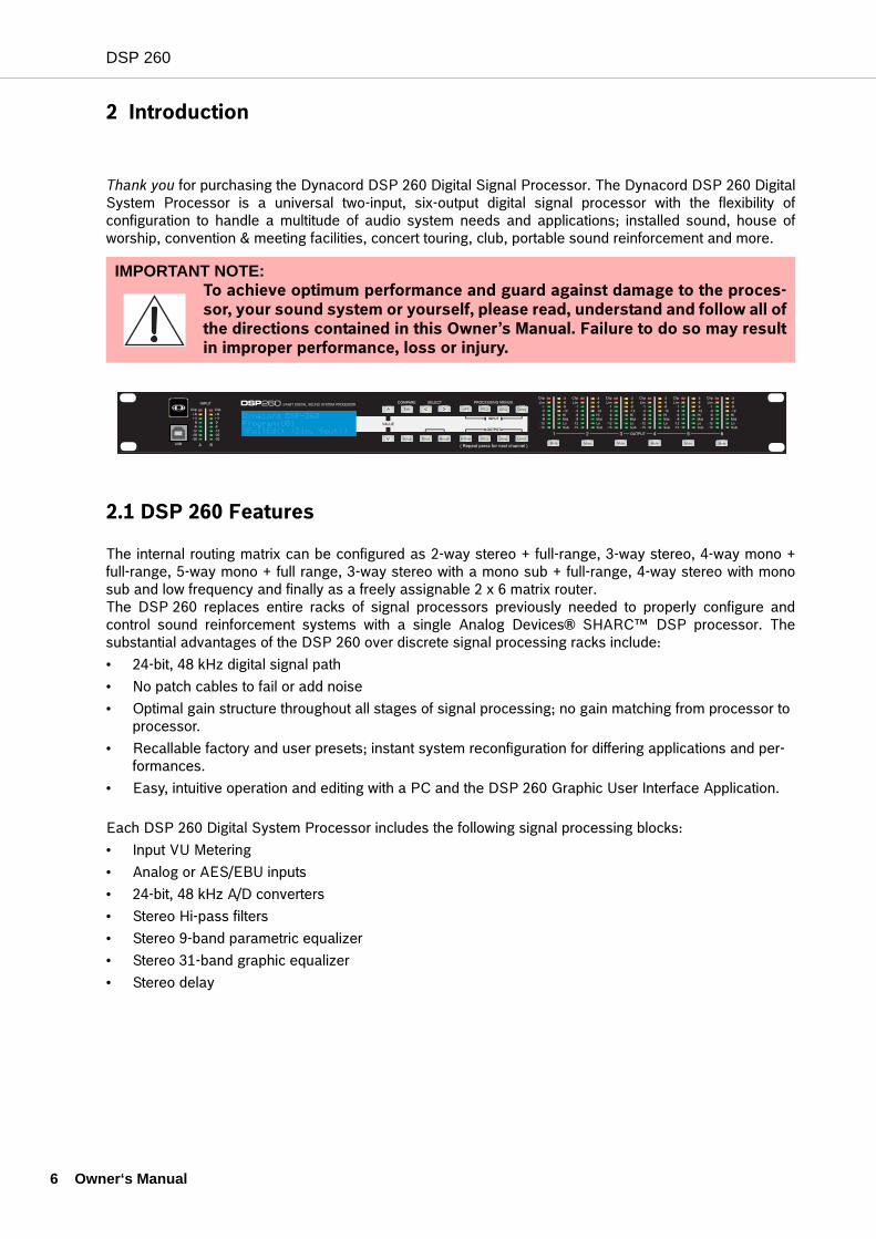
Thank you for purchasing the Dynacord DSP 260 Digital Signal Processor. The Dynacord DSP 260 DigitalSystem Processor is a universal two-input, six-output digital signal processor with the flexibility ofconfiguration to handle a multitude of audio system needs and applications; installed sound, house ofworship, convention & meeting facilities, concert touring, club, portable sound reinforcement and more.
2.1 DSP 260 Features
The internal routing matrix can be configured as 2-way stereo + full-range, 3-way stereo, 4-way mono +full-range, 5-way mono + full range, 3-way stereo with a mono sub + full-range, 4-way stereo with monosub and low frequency and finally as a freely assignable 2 x 6 matrix router.The DSP 260 replaces entire racks of signal processors previously needed to properly configure andcontrol sound reinforcement systems with a single Analog Devices® SHARC™ DSP processor. Thesubstantial advantages of the DSP 260 over discrete signal processing racks include:• 24-bit, 48 kHz digital signal path• No patch cables to fail or add noise• Optimal gain structure throughout all stages of signal processing; no gain matching from processor to
processor.• Recallable factory and user presets; instant system reconfiguration for differing applications and per-
formances.• Easy, intuitive operation and editing with a PC and the DSP 260 Graphic User Interface Application.
Each DSP 260 Digital System Processor includes the following signal processing blocks:• Input VU Metering• Analog or AES/EBU inputs• 24-bit, 48 kHz A/D converters• Stereo Hi-pass filters• Stereo 9-band parametric equalizer• Stereo 31-band graphic equalizer• Stereo delay
IMPORTANT NOTE:To achieve optimum performance and guard against damage to the proces-sor, your sound system or yourself, please read, understand and follow all ofthe directions contained in this Owner’s Manual. Failure to do so may resultin improper performance, loss or injury.
DelayGEQPEQ
LevelDelayPEQ
HPF>
X-OverRecallStore
<Edit>
Setup
Mute Mute Mute Mute Mute Mute
>
Dynacord DSP-260 Program:U01(FullEdit (2in. 6out))
ner‘s Manual
DSP 260
Matrix Router / Mixer
• Two inputs (stereo)• Summed left / right (mono) input• Six assignable outputs
Outputs (each)
• Cross-over (hi-pass / low-pass filters), with selectable filter types• 5-band parametric equalizer• Delay• Polarity• Peak RMS detecting limiter• Level & Mute• 24-bit, 48 kHz D/A converters
Additional features include:
• Electronically balanced XLR inputs and outputs• -6 dB switchable input level pad• Contact closure interface for recall of up to eight selectable presets• Front-panel USB port for connection to PC; preset editing and real time parameter control and monito-
ring. • Firmware updates• FLASH memory for preset storage and in-field firmware upgrades• Input level meters• 192 x 32 back-lit graphic LCD display• LCD navigation / editing controls• DSP block navigation short-cut controls• Output level meters• Output gain reduction meters• Output assignment display LEDs; sub, low, mid & high• Output channel Mute controls• Auto-ranging internal power supply; 100-240 V AC, 50-60 Hz• Standard IEC A.C. inlet with external, replaceable fuse
Owner‘s Manual 7
DSP 260
8 Ow
3 Controls & Connection
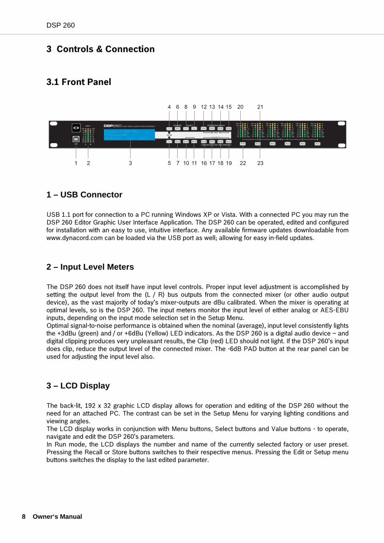
3.1 Front Panel
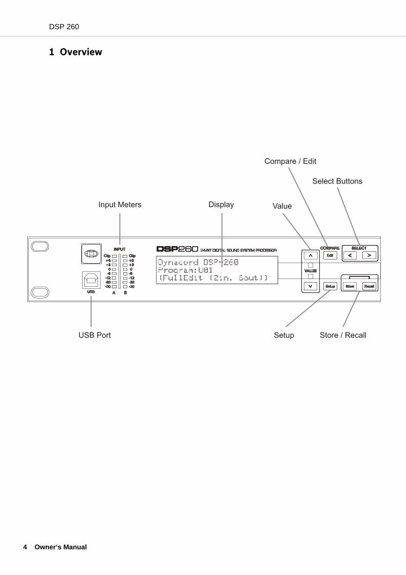
1 – USB Connector
USB 1.1 port for connection to a PC running Windows XP or Vista. With a connected PC you may run theDSP 260 Editor Graphic User Interface Application. The DSP 260 can be operated, edited and configuredfor installation with an easy to use, intuitive interface. Any available firmware updates downloadable fromwww.dynacord.com can be loaded via the USB port as well; allowing for easy in-field updates.
2 – Input Level Meters
The DSP 260 does not itself have input level controls. Proper input level adjustment is accomplished bysetting the output level from the (L / R) bus outputs from the connected mixer (or other audio outputdevice), as the vast majority of today’s mixer-outputs are dBu calibrated. When the mixer is operating atoptimal levels, so is the DSP 260. The input meters monitor the input level of either analog or AES-EBUinputs, depending on the input mode selection set in the Setup Menu. Optimal signal-to-noise performance is obtained when the nominal (average), input level consistently lightsthe +3dBu (green) and / or +6dBu (Yellow) LED indicators. As the DSP 260 is a digital audio device – anddigital clipping produces very unpleasant results, the Clip (red) LED should not light. If the DSP 260’s inputdoes clip, reduce the output level of the connected mixer. The -6dB PAD button at the rear panel can beused for adjusting the input level also.
3 – LCD Display
The back-lit, 192 x 32 graphic LCD display allows for operation and editing of the DSP 260 without theneed for an attached PC. The contrast can be set in the Setup Menu for varying lighting conditions andviewing angles.The LCD display works in conjunction with Menu buttons, Select buttons and Value buttons - to operate,navigate and edit the DSP 260’s parameters.In Run mode, the LCD displays the number and name of the currently selected factory or user preset.Pressing the Recall or Store buttons switches to their respective menus. Pressing the Edit or Setup menubuttons switches the display to the last edited parameter.
ner‘s Manual
DSP 260
In Edit and Setup mode, the top line of the LCD display shows the currently selected parameter editscreen. Use the Select buttons to activate the top line of the display, and the value buttons to scroll throughavailable parameter edit screens.
4/5 – Value Up/Down Buttons
Depending on the current LCD screen, the Value Up/Down Buttons performs the following function:• Recall – Select forwards/backwards through the stored preset list to select a preset to be recalled to
current memory.• Store – Select User Preset destinations forwards/backwards to select a destination for the currently
edited preset, scroll forwards through ANSI character set to name preset.• Edit / Setup – Scroll forwards/backwards through Edit / Setup screens when the top line of the LCD
screen is active. Scroll forwards through values for the selected parameter in an Edit / Setup screen.
6 – Edit / Compare Button
Pressing the Edit button while in Run mode places the current preset in Edit mode and the Edit buttonlights. The LCD display shows the last edit screen that was selected. From this point, any edit screen canbe displayed and altered.Pressing the Edit button again “compares” the edited preset, if parameters have been altered, to theoriginal un-edited preset. This compare function will audibly switch between the altered parameters andthe previously stored settings, allowing you to hear the effect of any DSP changes that have been made.Use this feature to monitor progress in editing or creating presets. Subsequently recalling a new preset will prompt you to save changes, which you may do or not.
7 – Setup Button
Pressing the Setup button while in Run mode displays the Setup menus in the LCD display and the Setupbutton lights. In this mode, any Setup menu can be displayed and altered. Changes made to Setup menuitems are saved automatically. To exit Setup mode, press the Setup button again. The LCD display will revert to Run mode.
8 – Select < Button
The Select < button is pressed to navigate backwards through Edit, Setup and / or Recall menu displayed.The button cycles through all available value fields in a screen and wraps around from first to last.
9 – Select > Button
The Select > button is pressed to navigate forwards through Edit, Setup and / or Recall menu displayed.The button cycles through all available value fields in a screen and wraps around from last to first.
Owner‘s Manual 9
DSP 260
10 O
10 – Store Button
Pressing the Store button while in Run mode displays the Store Preset screen in the LCD display and theStore button lights. In this screen edited presets can be named and saved to a user preset location.Pressing the Store button again completes the preset save operation.To exit without storing the current preset, press the Edit or Setup buttons to return to the Run modescreen.
11 – Recall Button
Pressing the Recall button while in Run mode displays the Recall Preset screen in the LCD display and theRecall button lights. In this screen, any of the 60 factory and 20 user presets can be recalled into currentmemory. Pressing the Recall button again completes the preset load operation and returns the LCDdisplay to Run mode.To exit without storing the current preset, press the Edit or Setup buttons to return to the Run modescreen.
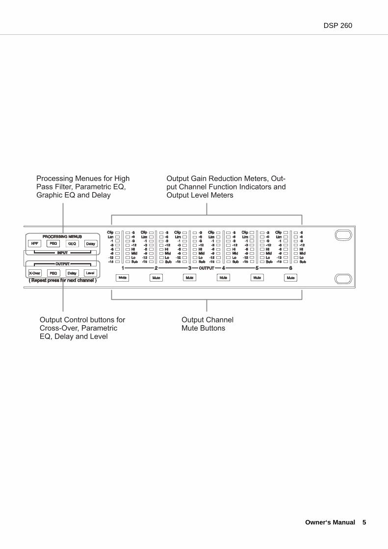
12 – Input HPF Button
Pressing the HPF button places the current preset in Edit mode and jumps to the Hi-Pass Filter screen ofInput A. Subsequent button presses toggle the display between Input A and Input B.
13 – Input PEQ Button
Pressing the PEQ button places the current preset in Edit mode and jumps to the first screen of the InputParametric Equalizer. Subsequent button presses toggle the display between Input A and Input B.
14 – Input GEQ Button
Pressing the GEQ button places the current preset in Edit mode and jumps to the the Input GraphicEqualizer screen. Subsequent button presses toggle the display between Input A and Input B.
15 – Input Delay Button
Pressing the Delay button places the current preset in Edit mode and jumps to the Input Delay screen.Subsequent button presses toggle the display between Input A and Input B.
wner‘s Manual
DSP 260
16 – Output X-Over Button
Pressing the X-Over button places the current preset in Edit mode and jumps to the first Output ChannelCross-Over screen. Subsequent button presses step through the available output channels (depending onconfiguration).
17 – Output PEQ Button
Pressing the PEQ button places the current preset in Edit mode and jumps to the first Output ParametricEqualizer screen. Subsequent button presses step through the available output channels (depending onconfiguration).
18 – Output Delay Button
Pressing the Delay button places the current preset in Edit mode and jumps to the Output Channel Delayscreen. Subsequent button presses step through the available output channels (depending onconfiguration).
19 – Output Level Button
Pressing the Level button places the current preset in Edit mode and jumps to the Output Channel Levelscreen. Subsequent button presses step through the available output channels (depending onconfiguration).
20 – Output Level Meters
Each output channel has an eight-segment output level VU meter. Meter response characteristics can beselected in the Setup menu: Normal Fast, Peak-Hold Slow Decay. The yellow segment indicates thatlimiting is being applied to the output channel. The red segments indicates clipping of the D/A convertersand should be avoided by adjusting the Output Level of the output channel. It is important to understandhow the meters work and what they are displaying. The Output Meters are displayed as “dB to LimiterThreshold”. In other words, these meters will display the headroom between the output level and the limiterthreshold. When viewed in conjunction with the Gain Reduction meters, this provides a complete display oflevel and headroom before and after limiting has been engaged to allow system levels to be optimized.This also means that the output metering will be displayed differently depending on the limiter thresholdsetting.
21 – Output Gain Reduction Meters
Each output channel has a four-segment gain reduction meter that shows the effect of the output channelLimiter on output level; from 0dB to -12dB.
Owner‘s Manual 11
DSP 260
12 O
22 – Output Channel Mute Buttons
Each output channel has a lighted Mute button. Pressing the Mute button turns off the output of thatchannel. The button lights red as an alert. Press the Mute button again to restore the output channel’ssignal. Output channels may also be muted from the DSP 260 Graphic User Interface Application, if the unit isconnected to a PC. Muting a channel in any window of the application will light the channel Mute button onthe front panel of the unit as well.
23 – Output Channel Function Indicators
Each output channel has a four-segment function display for informational purposes only. For any givenconfiguration possible with the DSP 260, an output channel may be identified as a sub, low, low/mid, mid,mid/hi, hi or full range output. One or two adjacent LED are displayed to indicate all possible outputbandpasses. (Full range is indicated by all lit LED’s.)
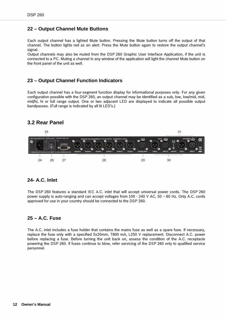
3.2 Rear Panel
24- A.C. Inlet
The DSP 260 features a standard IEC A.C. inlet that will accept universal power cords. The DSP 260power supply is auto-ranging and can accept voltages from 100 - 240 V AC, 50 – 60 Hz. Only A.C. cordsapproved for use in your country should be connected to the DSP 260.
25 – A.C. Fuse
The A.C. inlet includes a fuse holder that contains the mains fuse as well as a spare fuse. If necessary,replace the fuse only with a specified 5x20mm, T800 mA, L250 V replacement. Disconnect A.C. powerbefore replacing a fuse. Before turning the unit back on, assess the condition of the A.C. receptaclepowering the DSP 260. If fuses continue to blow, refer servicing of the DSP 260 only to qualified servicepersonnel.
wner‘s Manual
DSP 260
26 – A.C. Power Switch
The A.C. power switch turns power to the DSP 260 On and Off.
27 – Link/Relay Interface
The operating mode of this dual purpose interface is selected in the Setup menu. Operating modes are:• RS-232 Interface - Used to link two DSP 260s together in a Master/Slave setup. Connection is made
via a standard 9-pin null-modem serial interface cable with female connectors.• Contact Closure Port - Eight contact closure pins plus ground for interfacing to 5 V contact closure
systems. Each pin can be assigned a preset that is recalled when voltage on that pin is detected. The lowest pin number takes priority in multiple controller systems.
28 – Balanced XLR Outputs
Each output channel has an electronically balanced XLR connector for connection to system amplifiers.Each output channel can output different frequency ranges depending on its assignment and cross-oversettings.
29 – AES/EBU Digital Input
In addition to the analog audio inputs, an AES/EBU digital stereo input is provided and selectable in theSetup menu. The input conforms to IEC standard 60958 Type I. Connections must be made with three-conductor, 110-Ohm, twisted pair cabling and an XLR connector.
30 – Balanced XLR Thru
Each analog audio input is connected to an electronically buffered and balanced output as a throughconnector. The signal does not undergo any digital conversion or processing. These connectors are usedto pass input audio to a second DSP 260 used as a slave or to other audio inputs in the system.
31 – Balanced XLR Inputs
Each input has an electronically balanced, locking XLR connector. In stereo or dual modes, connections toboth inputs must be made. In mono modes, only one connection need be made, typically to Input A.
Care must be taken to assure that each output is connected to an appropriateamplifier and loudspeaker to avoid damage or unexpected results. Note thata new preset may change the assignment of channel and its frequency range.For instance an output assigned to Hi frequency speakers in one preset, maybe assigned as a sub output in another. See “Configurations of the DSP 260”.
Owner‘s Manual 13
DSP 260
14 O
32 – 6dB Pad
Input levels to the DSP 260 can be reduced 6dB prior to the A/D converter to compensate for higher-leveloutput from mixers and other audio devices. For ideal signal to noise performance when connecting theDSP 260 to high output level devices engage the 6dB pad rather than turning down the output of theconnected device. The DSP 260‘s Input level Meters (2) will indicate incoming signal level and whetherattenuation is required.
3.3 Installation
For proper operation, all directions regarding installation and connection must be followed.
Mounting
The DSP 260 should be mounted in a rack-mount enclosure or rack rails. The unit is 1RU tall by 14”(353mm) deep. Proper clearance for air circulation around the unit must be provided. Do not block anyvent holes on the unit. All four mounting points provided by the rack ears must be secured.
Power Connection
The DSP 260 must be connected to A.C. power only by means of the provided IEC A.C. cable or by apower cable provided by the dealer / installer to match the configuration of your country or region. TheDSP 260 must only be connected to a properly wired, three pin, grounded A.C. outlet. A.C. power mustrange from 100 – 240VAC, 50 – 60Hz. The DSP 260 internal power supply is an auto-ranging design; noadjustments are necessary to configure it for proper A.C. power.
Audio Cables
Always use correctly shielded audio cables when connecting to the DSP 260.
Balanced Input / Output ConnectionsTo minimize induced noise caused by audio cables and to maximize the length of cables used, balancedconnections are strongly advised for both Inputs and Outputs. The XLR jacks provided on the DSP 260 areconfigured as pin 1 ground, pin 2 hot (+), pin 3 cold (-). Cable shielding must be connected to pin 1. XLR –XLR cables or ¼” tip-ring-sleeve – XLR cables can both be used for balanced connections to the DSP 260.
wner‘s Manual

DSP 260
Un-balanced Input / Output ConnectionsUn-balanced connections can be made to the DSP 260, although induced noise from cabling may beincreased. Cables should also be less than 15” (5m) in length. Unbalanced connections can be 6dB lowerin level as well. To match the audio level obtained with a balanced connection, it is necessary to tie pin 3 toground at the XLR connector. This may increase noise.
RS-232
Two DSP 260s can be used in combination as a Master / Slave for managing largersound reinforcement systems. A 9-pin D-Sub connector is provided on the rear ofeach unit for data line connections. A standard female-to-female RS-232 cable thatconforms to the null modem wiring convention is used to connect the two units. Cablelength should be kept to less than 45 feet (15 m) for the most reliable operation.These cables are readily available at local computer dealers. Operation of the DSP 260 9-pin port for RS-232 connections is selected in the Setupmenu.
Relay Contact Closure
The same 9-pin port used for RS-232 connection to another DSP 260can alternately be used to recall presets from relay contact closures.Pins 1 – 4 and pins 5 – 9 are the input lines and pin 5 provides theground reference. When the DSP 260 detects a connection betweenpin-5 ground and input pins, as completed by an external relay, apreset assigned by the user to input pins is recalled into memory andthe DSP 260 returns to run-time mode.
Owner‘s Manual 15
DSP 260
16 O
USB
Connecting the DSP 260 to a PC for operation via the DSP 260 Graphic User Interface application isaccomplished via the front panel USB port. The port conforms to the USB 1.1 Type B specification. Type BUSB cables are readily available at computer dealers.
Connection to Amplifiers
It is very important to confirm correct connection to all amplifiers. DSP 260 has the ability toconfigure each output for a specific frequency range; sub, low freq. mid freq, high freq. Youmust make sure that each output is connected to the correct amplifier and loudspeaker(s).Incorrect connections could lead to unexpected results or damage to loudspeakercomponents.Note also that each preset in the DSP 260 includes DSP and bandpass parameters for theoutput channels. It is possible for a new preset to change an output from Hi to Sub, forinstance. Make sure that connections to amplifiers and loudspeakers are correct beforeusing a new preset.
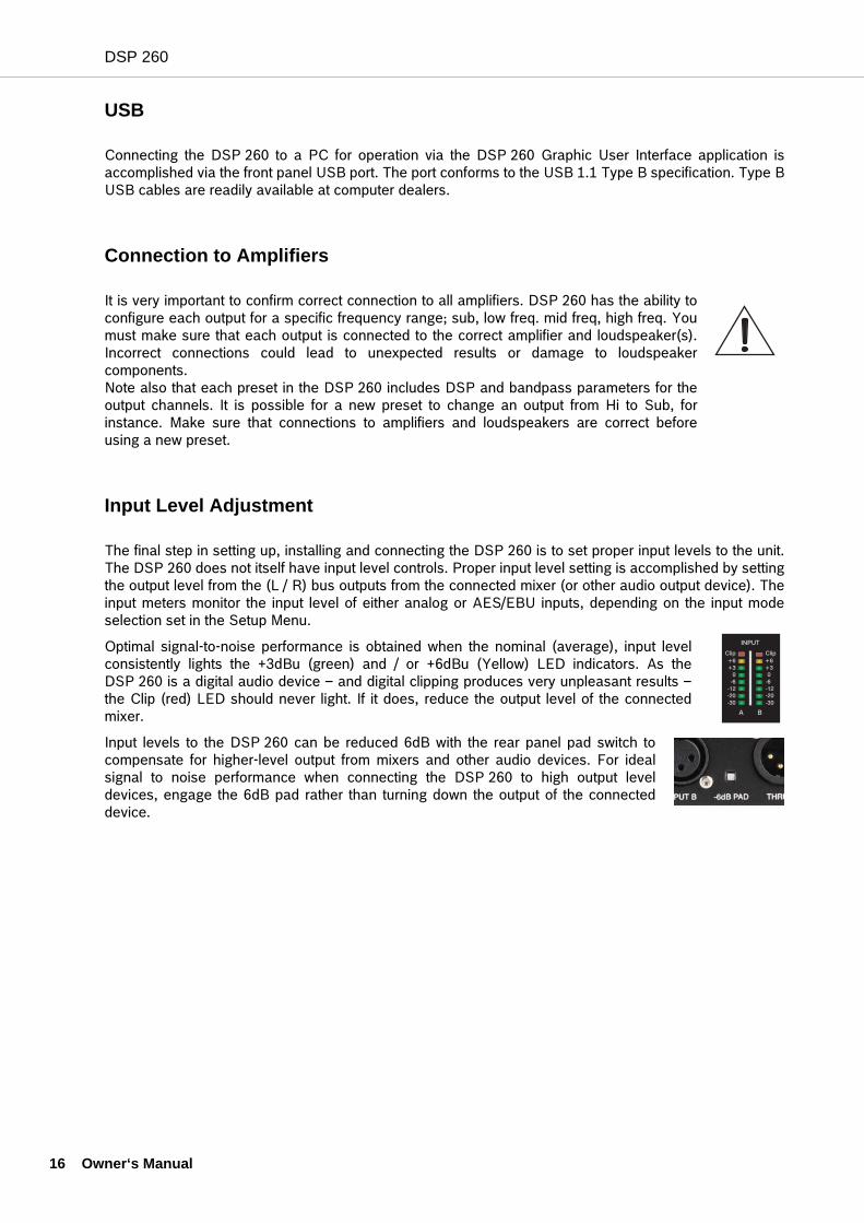
Input Level Adjustment
The final step in setting up, installing and connecting the DSP 260 is to set proper input levels to the unit.The DSP 260 does not itself have input level controls. Proper input level setting is accomplished by settingthe output level from the (L / R) bus outputs from the connected mixer (or other audio output device). Theinput meters monitor the input level of either analog or AES/EBU inputs, depending on the input modeselection set in the Setup Menu.
Optimal signal-to-noise performance is obtained when the nominal (average), input levelconsistently lights the +3dBu (green) and / or +6dBu (Yellow) LED indicators. As theDSP 260 is a digital audio device – and digital clipping produces very unpleasant results –the Clip (red) LED should never light. If it does, reduce the output level of the connectedmixer.
Input levels to the DSP 260 can be reduced 6dB with the rear panel pad switch tocompensate for higher-level output from mixers and other audio devices. For idealsignal to noise performance when connecting the DSP 260 to high output leveldevices, engage the 6dB pad rather than turning down the output of the connecteddevice.
wner‘s Manual
DSP 260
Owner‘s Manual 17
4 Editing & Operation
4.1 Factory Presets
The DSP 260 comes with 60 factory presets to configure and manage typical sound reinforcementsystems. Factory presets can be recalled at will. Limited editing can be performed from the front-panelLCD user interface such as output level, mute and limiter threshold setting. Installers can identify factorypresets with system configurations that are not appropriate for the given installation and lock-out and hidethem from the operator.
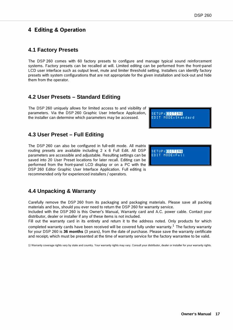
4.2 User Presets – Standard Editing
The DSP 260 uniquely allows for limited access to and visibility ofparameters. Via the DSP 260 Graphic User Interface Application,the installer can determine which parameters may be accessed.
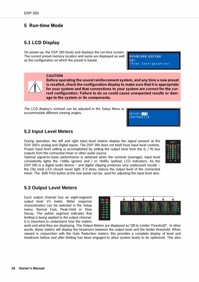
4.3 User Preset – Full Editing
The DSP 260 can also be configured in full-edit mode. All matrixrouting presets are available including 2 x 6 Full Edit. All DSPparameters are accessible and adjustable. Resulting settings can besaved into 20 User Preset locations for later recall. Editing can beperformed from the front-panel LCD display or on a PC with theDSP 260 Editor Graphic User Interface Application. Full editing isrecommended only for experienced installers / operators.
4.4 Unpacking & Warranty
Carefully remove the DSP 260 from its packaging and packaging materials. Please save all packingmaterials and box, should you ever need to return the DSP 260 for warranty service.Included with the DSP 260 is this Owner’s Manual, Warranty card and A.C. power cable. Contact yourdistributor, dealer or installer if any of these items is not included. Fill out the warranty card in its entirety and return it to the address noted. Only products for whichcompleted warranty cards have been received will be covered fully under warranty.1 The factory warrantyfor your DSP 260 is 36 months (3 years), from the date of purchase. Please save the warranty certificateand receipt; which must be presented at the time of warranty service for the factory warrantee to be valid.
1) Warranty coverage rights vary by state and country. Your warranty rights may vary. Consult your distributor, dealer or installer for your warranty rights.
DSP 260
18 O
5 Run-time Mode
5.1 LCD Display
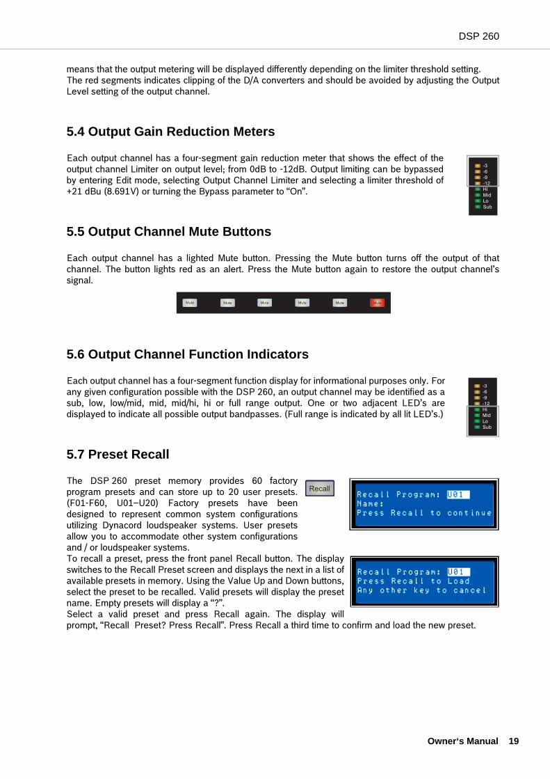
On power-up, the DSP 260 boots and displays the run-time screen.The current preset memory location and name are displayed as wellas the configuration on which the preset is based.
The LCD display‘s contrast can be adjusted in the Setup Menu toaccommodate different viewing angles.
5.2 Input Level Meters
During operation, the left and right input level meters display the signal present at theDSP 260’s analog and Digital inputs. The DSP 260 does not itself have input level controls.Proper input level setting is accomplished by setting the output level from the (L / R) busoutputs from the connected mixer or other audio source.Optimal signal-to-noise performance is obtained when the nominal (average), input levelconsistently lights the +3dBu (green) and / or +6dBu (yellow) LED indicators. As theDSP 260 is a digital audio device – and digital clipping produces very unpleasant results –the Clip (red) LED should never light. If it does, reduce the output level of the connectedmixer. The -6dB PAD button at the rear panel can be used for adjusting the input level also.
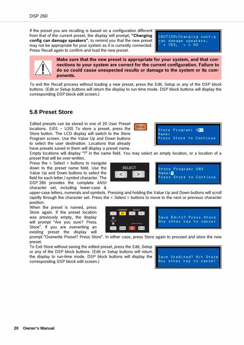
5.3 Output Level Meters
Each output channel has an eight-segmentoutput level VU meter. Meter responsecharacteristics can be selected in the Setupmenu: Normal Fast, Peak-Hold or SlowDecay. The yellow segment indicates thatlimiting is being applied to the output channel.It is important to understand how the meterswork and what they are displaying. The Output Meters are displayed as “dB to Limiter Threshold”. In otherwords, these meters will display the headroom between the output level and the limiter threshold. Whenviewed in conjunction with the Gain Reduction meters, this provides a complete display of level andheadroom before and after limiting has been engaged to allow system levels to be optimized. This also
CAUTIONBefore operating the sound reinforcement system, and any time a new presetis recalled, check the configuration display to make sure that it is appropriatefor your system and that connections to your system are correct for the cur-rent configuration. Failure to do so could cause unexpected results or dam-age to the system or its components.
wner‘s Manual
DSP 260
means that the output metering will be displayed differently depending on the limiter threshold setting. The red segments indicates clipping of the D/A converters and should be avoided by adjusting the OutputLevel setting of the output channel.
5.4 Output Gain Reduction Meters
Each output channel has a four-segment gain reduction meter that shows the effect of theoutput channel Limiter on output level; from 0dB to -12dB. Output limiting can be bypassedby entering Edit mode, selecting Output Channel Limiter and selecting a limiter threshold of+21 dBu (8.691V) or turning the Bypass parameter to “On”.
5.5 Output Channel Mute Buttons
Each output channel has a lighted Mute button. Pressing the Mute button turns off the output of thatchannel. The button lights red as an alert. Press the Mute button again to restore the output channel’ssignal.
5.6 Output Channel Function Indicators
Each output channel has a four-segment function display for informational purposes only. Forany given configuration possible with the DSP 260, an output channel may be identified as asub, low, low/mid, mid, mid/hi, hi or full range output. One or two adjacent LED’s aredisplayed to indicate all possible output bandpasses. (Full range is indicated by all lit LED’s.)
5.7 Preset Recall
The DSP 260 preset memory provides 60 factoryprogram presets and can store up to 20 user presets.(F01-F60, U01–U20) Factory presets have beendesigned to represent common system configurationsutilizing Dynacord loudspeaker systems. User presetsallow you to accommodate other system configurationsand / or loudspeaker systems. To recall a preset, press the front panel Recall button. The displayswitches to the Recall Preset screen and displays the next in a list ofavailable presets in memory. Using the Value Up and Down buttons,select the preset to be recalled. Valid presets will display the presetname. Empty presets will display a “?”.Select a valid preset and press Recall again. The display willprompt, “Recall Preset? Press Recall”. Press Recall a third time to confirm and load the new preset.
Recall
Owner‘s Manual 19
DSP 260
20 O
If the preset you are recalling is based on a configuration differentfrom that of the current preset, the display will prompt, “Changingconfig can damage speakers”, to remind you that the new presetmay not be appropriate for your system as it is currently connected.Press Recall again to confirm and load the new preset.
To exit the Recall process without loading a new preset, press the Edit, Setup or any of the DSP blockbuttons. (Edit or Setup buttons will return the display to run-time mode. DSP block buttons will display thecorresponding DSP block edit screen.)
5.8 Preset Store
Edited presets can be stored in one of 20 User Presetlocations. (U01 – U20) To store a preset, press theStore button. The LCD display will switch to the StoreProgram screen. Use the Value Up and Down buttonsto select the user destination. Locations that alreadyhave presets saved in them will display a preset name.Empty locations will display “?” in the name field. You may select an empty location, or a location of apreset that will be over-written. Press the < Select > buttons to navigatedown to the preset name field. Use theValue Up and Down buttons to select thefield for each letter / symbol character. TheDSP 260 provides the complete ANSIcharacter set, including lower-case &upper-case letters, numerals and symbols. Pressing and holding the Value Up and Down buttons will scrollrapidly through the character set. Press the < Select > buttons to move to the next or previous characterposition. When the preset is named, pressStore again. If the preset locationwas previously empty, the displaywill prompt “Are you sure? PressStore”. If you are overwriting anexisting preset the display willprompt “Overwrite Preset? Press Store”. In either case, press Store again to proceed and store the newpreset. To Exit Store without saving the edited preset, press the Edit, Setupor any of the DSP block buttons. (Edit or Setup buttons will returnthe display to run-time mode. DSP block buttons will display thecorresponding DSP block edit screen.)
Make sure that the new preset is appropriate for your system, and that con-nections to your system are correct for the current configuration. Failure todo so could cause unexpected results or damage to the system or its com-ponents.
Store
wner‘s Manual
DSP 260
5.9 Edit
Both Factory and User preset can be edited, but edited presets can only be stored in User preset locations.
Standard Edit Mode
The DSP 260 defaults to Standard Edit mode wherein, input and output channel parameters areappropriately linked. (Refer to “Configurations” illustrations to see which channels are parameter-linked foreach configuration.Linked parameters are always identical in value. For instance, setting a graphic eq curve for Input A, setsthe same curve for Input B, if the configuration has linked stereo inputs. Either input channel can be edited;changes will be reflected in both. The same is true for parameters of linked output channels. The onlyexception to the linking of parameters is the Mute buttons. Output channels can be individually muted atany time, either from the DSP 260 front panel or the Graphic User Interface application.
Full Edit Mode
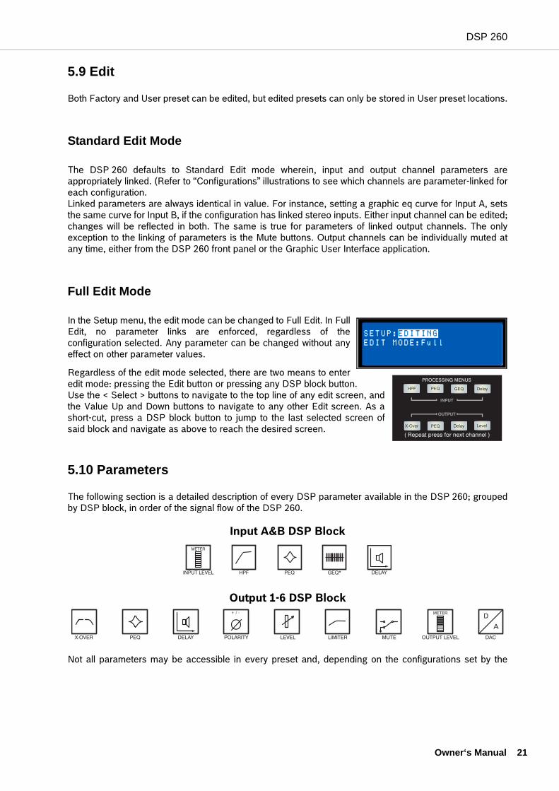
In the Setup menu, the edit mode can be changed to Full Edit. In FullEdit, no parameter links are enforced, regardless of theconfiguration selected. Any parameter can be changed without anyeffect on other parameter values.
Regardless of the edit mode selected, there are two means to enteredit mode: pressing the Edit button or pressing any DSP block button. Use the < Select > buttons to navigate to the top line of any edit screen, andthe Value Up and Down buttons to navigate to any other Edit screen. As ashort-cut, press a DSP block button to jump to the last selected screen ofsaid block and navigate as above to reach the desired screen.
5.10 Parameters
The following section is a detailed description of every DSP parameter available in the DSP 260; groupedby DSP block, in order of the signal flow of the DSP 260.
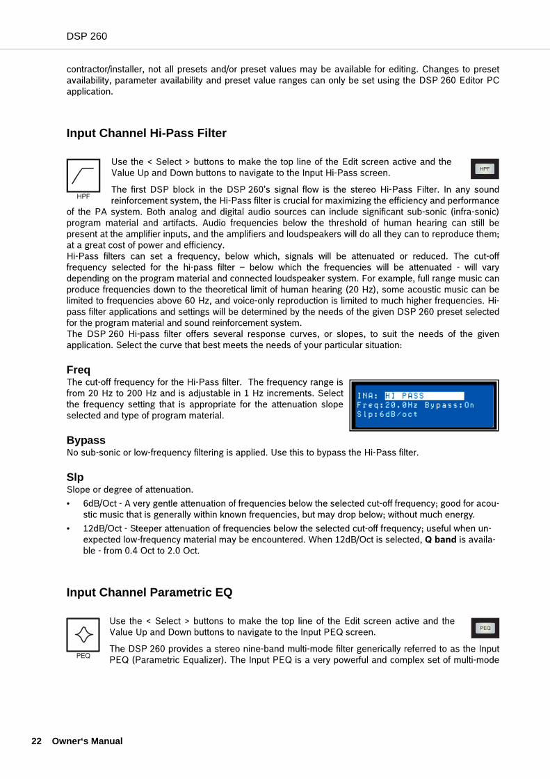
Input A&B DSP Block
Output 1-6 DSP Block
Not all parameters may be accessible in every preset and, depending on the configurations set by the
Owner‘s Manual 21
DSP 260
22 O
contractor/installer, not all presets and/or preset values may be available for editing. Changes to presetavailability, parameter availability and preset value ranges can only be set using the DSP 260 Editor PCapplication.
Input Channel Hi-Pass Filter
Use the < Select > buttons to make the top line of the Edit screen active and theValue Up and Down buttons to navigate to the Input Hi-Pass screen.
The first DSP block in the DSP 260’s signal flow is the stereo Hi-Pass Filter. In any soundreinforcement system, the Hi-Pass filter is crucial for maximizing the efficiency and performance
of the PA system. Both analog and digital audio sources can include significant sub-sonic (infra-sonic)program material and artifacts. Audio frequencies below the threshold of human hearing can still bepresent at the amplifier inputs, and the amplifiers and loudspeakers will do all they can to reproduce them;at a great cost of power and efficiency. Hi-Pass filters can set a frequency, below which, signals will be attenuated or reduced. The cut-offfrequency selected for the hi-pass filter – below which the frequencies will be attenuated - will varydepending on the program material and connected loudspeaker system. For example, full range music canproduce frequencies down to the theoretical limit of human hearing (20 Hz), some acoustic music can belimited to frequencies above 60 Hz, and voice-only reproduction is limited to much higher frequencies. Hi-pass filter applications and settings will be determined by the needs of the given DSP 260 preset selectedfor the program material and sound reinforcement system.The DSP 260 Hi-pass filter offers several response curves, or slopes, to suit the needs of the givenapplication. Select the curve that best meets the needs of your particular situation:
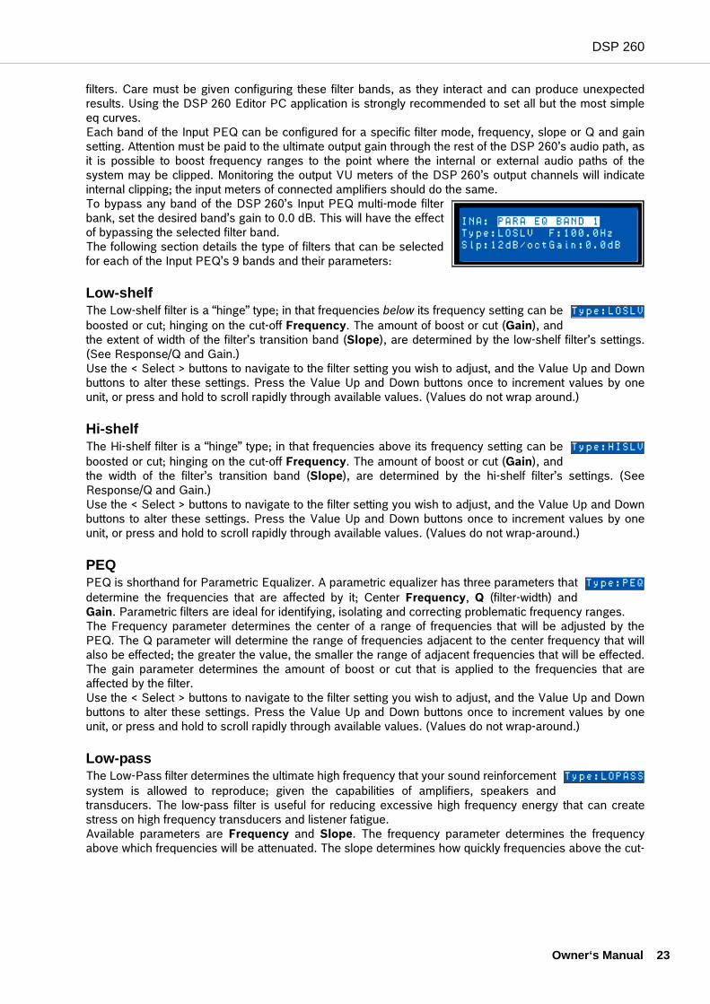
FreqThe cut-off frequency for the Hi-Pass filter. The frequency range isfrom 20 Hz to 200 Hz and is adjustable in 1 Hz increments. Selectthe frequency setting that is appropriate for the attenuation slopeselected and type of program material.
BypassNo sub-sonic or low-frequency filtering is applied. Use this to bypass the Hi-Pass filter.
SlpSlope or degree of attenuation.• 6dB/Oct - A very gentle attenuation of frequencies below the selected cut-off frequency; good for acou-
stic music that is generally within known frequencies, but may drop below; without much energy.• 12dB/Oct - Steeper attenuation of frequencies below the selected cut-off frequency; useful when un-
expected low-frequency material may be encountered. When 12dB/Oct is selected, Q band is availa-ble - from 0.4 Oct to 2.0 Oct.
Input Channel Parametric EQ
Use the < Select > buttons to make the top line of the Edit screen active and theValue Up and Down buttons to navigate to the Input PEQ screen.
The DSP 260 provides a stereo nine-band multi-mode filter generically referred to as the InputPEQ (Parametric Equalizer). The Input PEQ is a very powerful and complex set of multi-mode
wner‘s Manual
DSP 260
filters. Care must be given configuring these filter bands, as they interact and can produce unexpectedresults. Using the DSP 260 Editor PC application is strongly recommended to set all but the most simpleeq curves. Each band of the Input PEQ can be configured for a specific filter mode, frequency, slope or Q and gainsetting. Attention must be paid to the ultimate output gain through the rest of the DSP 260’s audio path, asit is possible to boost frequency ranges to the point where the internal or external audio paths of thesystem may be clipped. Monitoring the output VU meters of the DSP 260’s output channels will indicateinternal clipping; the input meters of connected amplifiers should do the same.To bypass any band of the DSP 260’s Input PEQ multi-mode filterbank, set the desired band’s gain to 0.0 dB. This will have the effectof bypassing the selected filter band. The following section details the type of filters that can be selectedfor each of the Input PEQ’s 9 bands and their parameters:
Low-shelfThe Low-shelf filter is a “hinge” type; in that frequencies below its frequency setting can beboosted or cut; hinging on the cut-off Frequency. The amount of boost or cut (Gain), andthe extent of width of the filter’s transition band (Slope), are determined by the low-shelf filter’s settings.(See Response/Q and Gain.)Use the < Select > buttons to navigate to the filter setting you wish to adjust, and the Value Up and Downbuttons to alter these settings. Press the Value Up and Down buttons once to increment values by oneunit, or press and hold to scroll rapidly through available values. (Values do not wrap around.)
Hi-shelfThe Hi-shelf filter is a “hinge” type; in that frequencies above its frequency setting can beboosted or cut; hinging on the cut-off Frequency. The amount of boost or cut (Gain), andthe width of the filter’s transition band (Slope), are determined by the hi-shelf filter’s settings. (SeeResponse/Q and Gain.)Use the < Select > buttons to navigate to the filter setting you wish to adjust, and the Value Up and Downbuttons to alter these settings. Press the Value Up and Down buttons once to increment values by oneunit, or press and hold to scroll rapidly through available values. (Values do not wrap-around.)
PEQPEQ is shorthand for Parametric Equalizer. A parametric equalizer has three parameters thatdetermine the frequencies that are affected by it; Center Frequency, Q (filter-width) andGain. Parametric filters are ideal for identifying, isolating and correcting problematic frequency ranges.The Frequency parameter determines the center of a range of frequencies that will be adjusted by thePEQ. The Q parameter will determine the range of frequencies adjacent to the center frequency that willalso be effected; the greater the value, the smaller the range of adjacent frequencies that will be effected.The gain parameter determines the amount of boost or cut that is applied to the frequencies that areaffected by the filter.Use the < Select > buttons to navigate to the filter setting you wish to adjust, and the Value Up and Downbuttons to alter these settings. Press the Value Up and Down buttons once to increment values by oneunit, or press and hold to scroll rapidly through available values. (Values do not wrap-around.)
Low-passThe Low-Pass filter determines the ultimate high frequency that your sound reinforcementsystem is allowed to reproduce; given the capabilities of amplifiers, speakers andtransducers. The low-pass filter is useful for reducing excessive high frequency energy that can createstress on high frequency transducers and listener fatigue.Available parameters are Frequency and Slope. The frequency parameter determines the frequencyabove which frequencies will be attenuated. The slope determines how quickly frequencies above the cut-
Owner‘s Manual 23
DSP 260
24 O
off frequency will be attenuated. (See response curve.)Use the < Select > buttons to navigate to the filter setting you wish to adjust, and the Value Up and Downbuttons to alter these settings. Press the Value Up and Down buttons once to increment values by oneunit, or press and hold to scroll rapidly through available values. (Values do not wrap-around.)
Hi-passThe Hi-Pass filter determines the ultimate low frequency that your sound reinforcementsystem is allowed to reproduce; given the capabilities of amplifiers, speakers andtransducers. Keep in mind that the DSP 260 signal path already includes a hi-pass filter prior to the InputPEQ DSP block. Settings to this filter in most configurations may be redundant or interactive with the initialHi-Pass filter.Available parameters are Frequency and Slope. The frequency parameter determines the frequencybelow which frequencies will be attenuated. The slope determines how quickly frequencies below that willbe attenuated. (See response curve.)Use the < Select > buttons to navigate to the filter setting you wish to adjust, and the Value Up and Downbuttons to alter these settings. Press the Value Up and Down buttons once to increment values by oneunit, or press and hold to scroll rapidly through available values. (Values do not wrap-around.)
Input Channel GEQ (Graphic Equalizer) (available soon)Use the < Select > buttons to make the top line of the Edit screen active and the Value Up and Downbuttons to navigate to the Input GEQ screen.The DSP 260’s input signal path includes a stereo 31-band graphic equalizer after the stereo 9-band PEQin the signal path. This DSP block can be used for very precisely identifying, isolating and correctingproblematic frequency ranges.Keep in mind that changes to the Input GEQ will be interactive with adjustments made in the Input PEQ.Unexpected results can occur. Press the < Select > buttons to move the cursor down into the GEQ frequency adjustment field.Subsequent presses of the < Select > buttons will move the cursor forward or backwards through thefrequency adjustment field; from band to band. The selected frequency’s “fader” is highlighted in thedisplay. As each band is selected, its center frequency and current cut/boost setting is displayed on the topline of the LCD display. To adjust the amount of boost or cut for a selected frequency band, select the band with the < Select >buttons and press the Value Up or Down buttons as required. The LCD display will reflect your changes by
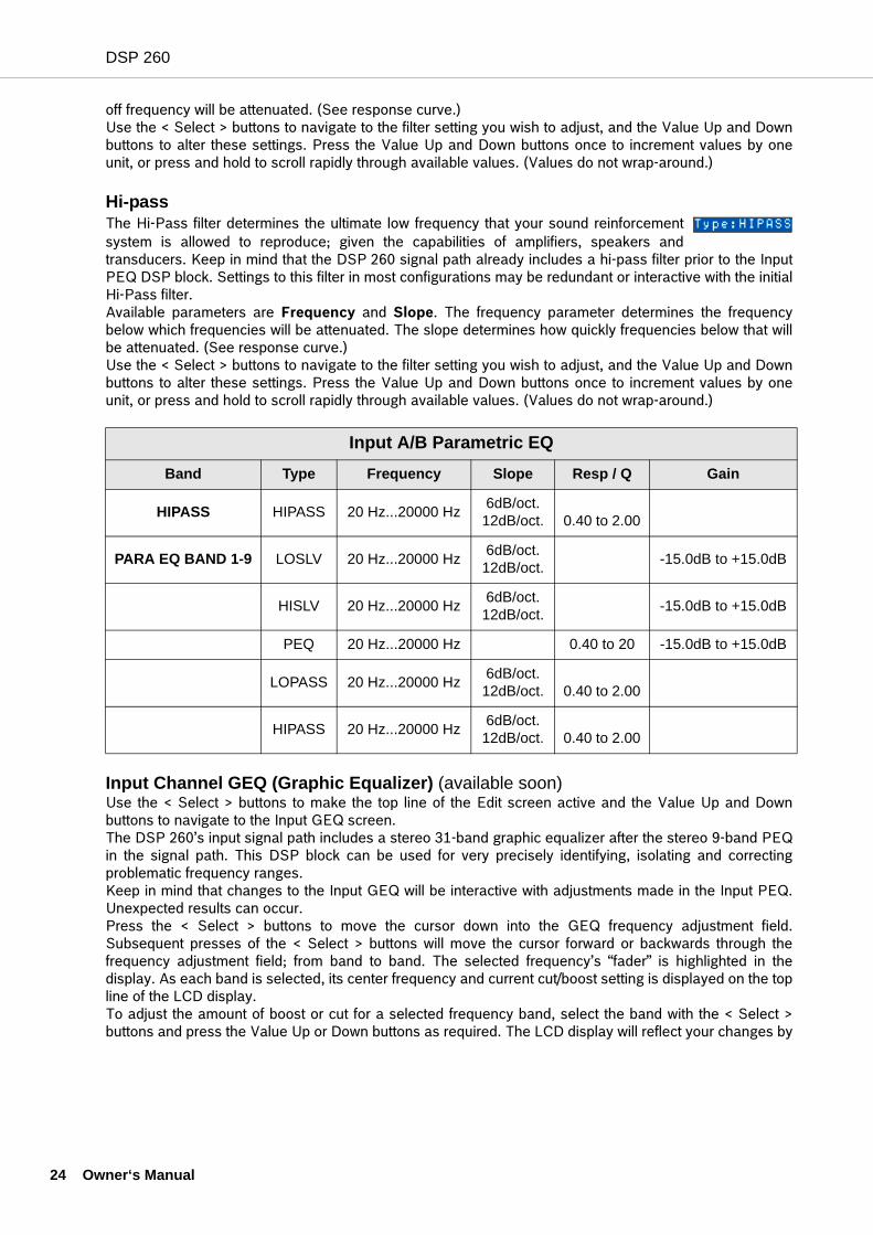
Input A/B Parametric EQBand Type Frequency Slope Resp / Q Gain
HIPASS HIPASS 20 Hz...20000 Hz 6dB/oct.12dB/oct. 0.40 to 2.00
PARA EQ BAND 1-9 LOSLV 20 Hz...20000 Hz 6dB/oct.12dB/oct. -15.0dB to +15.0dB
HISLV 20 Hz...20000 Hz 6dB/oct.12dB/oct. -15.0dB to +15.0dB
PEQ 20 Hz...20000 Hz 0.40 to 20 -15.0dB to +15.0dB
LOPASS 20 Hz...20000 Hz 6dB/oct.12dB/oct. 0.40 to 2.00
HIPASS 20 Hz...20000 Hz 6dB/oct.12dB/oct. 0.40 to 2.00
wner‘s Manual
DSP 260
moving the selected frequency band’s “fader” up or down. To exit the Input GEQ edit screen, press the Input GEQ button, use the < Select > buttons to againhighlight the top line of the edit screen display or press any other DSP block button.
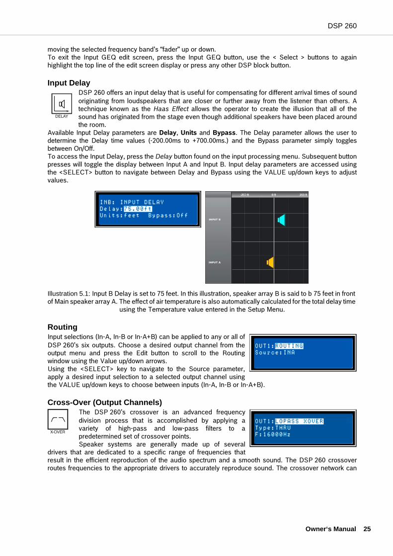
Input Delay DSP 260 offers an input delay that is useful for compensating for different arrival times of soundoriginating from loudspeakers that are closer or further away from the listener than others. Atechnique known as the Haas Effect allows the operator to create the illusion that all of thesound has originated from the stage even though additional speakers have been placed aroundthe room.
Available Input Delay parameters are Delay, Units and Bypass. The Delay parameter allows the user todetermine the Delay time values (-200.00ms to +700.00ms.) and the Bypass parameter simply togglesbetween On/Off.To access the Input Delay, press the Delay button found on the input processing menu. Subsequent buttonpresses will toggle the display between Input A and Input B. Input delay parameters are accessed usingthe <SELECT> button to navigate between Delay and Bypass using the VALUE up/down keys to adjustvalues.
RoutingInput selections (In-A, In-B or In-A+B) can be applied to any or all ofDSP 260’s six outputs. Choose a desired output channel from theoutput menu and press the Edit button to scroll to the Routingwindow using the Value up/down arrows. Using the <SELECT> key to navigate to the Source parameter,apply a desired input selection to a selected output channel usingthe VALUE up/down keys to choose between inputs (In-A, In-B or In-A+B).
Cross-Over (Output Channels)The DSP 260’s crossover is an advanced frequencydivision process that is accomplished by applying avariety of high-pass and low-pass filters to apredetermined set of crossover points. Speaker systems are generally made up of several
drivers that are dedicated to a specific range of frequencies thatresult in the efficient reproduction of the audio spectrum and a smooth sound. The DSP 260 crossoverroutes frequencies to the appropriate drivers to accurately reproduce sound. The crossover network can
Illustration 5.1: Input B Delay is set to 75 feet. In this illustration, speaker array B is said to b 75 feet in front of Main speaker array A. The effect of air temperature is also automatically calculated for the total delay time
using the Temperature value entered in the Setup Menu.
Owner‘s Manual 25
DSP 260
26 O
also be used to insure that low-frequency energy is not accidently routed to the mid-range or tweeterdrivers that may result in potential damage.Available DSP 260 crossover parameters are Type and Frequency.
To access the Crossover screen, press the X-Over button found on the output processing menu.Subsequent button presses will toggle the display between OUT1 to OUT6. Use the <SELECT>button to navigate between the Low Pass/parameters. Adjust the values of each parameter using
the up/down VALUE arrows. The DSP 260 Crossover offers a variety of HiPass and LoPass filters depending on the configurationoutput selected along with a variety of selectable filters and frequency ranges that are adjustable using theup/down VALUE arrows.
TypeType offers list of selectable slopes/response Q’s • Thru• 6dB• 12dB/ 0.5Q - 2.0Q• Bessel: 12 dB, 18 dB or 24 dB• Butterworth: 12dB, 18dB or 24 dB• Linkwitz-Riley: 12dB or 24 dB
Frequency Frequency offers a selectable frequency range from 20.0 Hz to 20,000Hz.
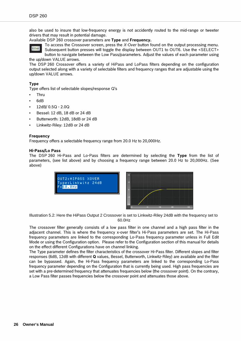
Hi-Pass/Lo Pass The DSP 260 Hi-Pass and Lo-Pass filters are determined by selecting the Type from the list ofparameters, (see list above) and by choosing a frequency range between 20.0 Hz to 20,000Hz. (Seeabove)
The crossover filter generally consists of a low pass filter in one channel and a high pass filter in theadjacent channel. This is where the frequency x-over filter’s Hi-Pass parameters are set. The Hi-Passfrequency parameters are linked to the corresponding Lo-Pass frequency parameter unless in Full EditMode or using the Configuration option. Please refer to the Configuration section of this manual for detailson the effect different Configurations have on channel linking. The Type parameter defines the filter characteristics of the crossover Hi-Pass filter. Different slopes and filterresponses (6dB, 12dB with different Q values, Bessel, Butterworth, Linkwitz-Riley) are available and the filtercan be bypassed. Again, the Hi-Pass frequency parameters are linked to the corresponding Lo-Passfrequency parameter depending on the Configuration that is currently being used. High pass frequencies areset with a pre-determined frequency that attenuates frequencies below (the crossover point). On the contrary,a Low Pass filter passes frequencies below the crossover point and attenuates those above.
Illustration 5.2: Here the HiPass Output 2 Crossover is set to Linkwitz-Riley 24dB with the frequency set to 60.0Hz
wner‘s Manual
DSP 260
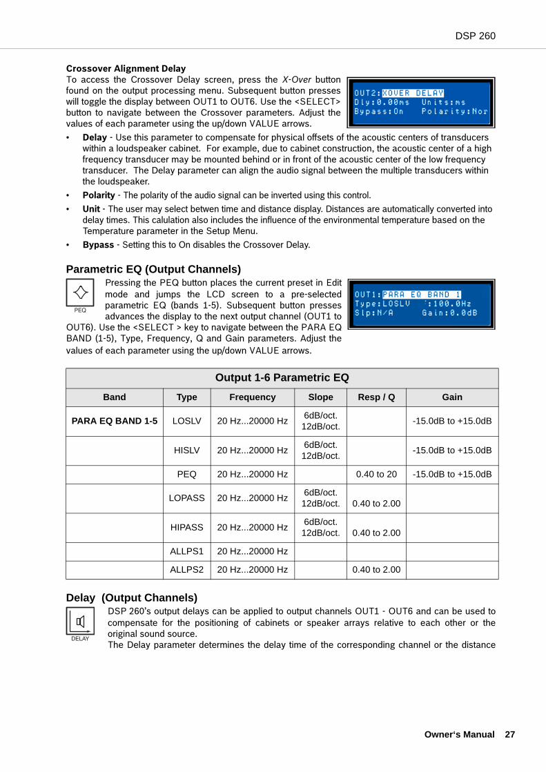
Crossover Alignment Delay To access the Crossover Delay screen, press the X-Over buttonfound on the output processing menu. Subsequent button presseswill toggle the display between OUT1 to OUT6. Use the <SELECT>button to navigate between the Crossover parameters. Adjust thevalues of each parameter using the up/down VALUE arrows.• Delay - Use this parameter to compensate for physical offsets of the acoustic centers of transducers
within a loudspeaker cabinet. For example, due to cabinet construction, the acoustic center of a high frequency transducer may be mounted behind or in front of the acoustic center of the low frequency transducer. The Delay parameter can align the audio signal between the multiple transducers within the loudspeaker.
• Polarity - The polarity of the audio signal can be inverted using this control.• Unit - The user may select betwen time and distance display. Distances are automatically converted into
delay times. This calulation also includes the influence of the environmental temperature based on the Temperature parameter in the Setup Menu.
• Bypass - Setting this to On disables the Crossover Delay.
Parametric EQ (Output Channels)Pressing the PEQ button places the current preset in Editmode and jumps the LCD screen to a pre-selectedparametric EQ (bands 1-5). Subsequent button pressesadvances the display to the next output channel (OUT1 to
OUT6). Use the <SELECT > key to navigate between the PARA EQBAND (1-5), Type, Frequency, Q and Gain parameters. Adjust thevalues of each parameter using the up/down VALUE arrows.
Delay (Output Channels)DSP 260’s output delays can be applied to output channels OUT1 - OUT6 and can be used tocompensate for the positioning of cabinets or speaker arrays relative to each other or theoriginal sound source.The Delay parameter determines the delay time of the corresponding channel or the distance
Output 1-6 Parametric EQBand Type Frequency Slope Resp / Q Gain
PARA EQ BAND 1-5 LOSLV 20 Hz...20000 Hz 6dB/oct.12dB/oct. -15.0dB to +15.0dB
HISLV 20 Hz...20000 Hz 6dB/oct.12dB/oct. -15.0dB to +15.0dB
PEQ 20 Hz...20000 Hz 0.40 to 20 -15.0dB to +15.0dB
LOPASS 20 Hz...20000 Hz 6dB/oct.12dB/oct. 0.40 to 2.00
HIPASS 20 Hz...20000 Hz 6dB/oct.12dB/oct. 0.40 to 2.00
ALLPS1 20 Hz...20000 Hz
ALLPS2 20 Hz...20000 Hz 0.40 to 2.00
Owner‘s Manual 27
DSP 260
28 O
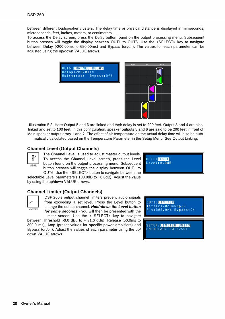
between different loudspeaker clusters. The delay time or physical distance is displayed in milliseconds,microseconds, feet, inches, meters, or centimeters. To access the Delay screen, press the Delay button found on the output processing menu. Subsequentbutton presses will toggle the display between OUT1 to OUT6. Use the <SELECT> key to navigatebetween Delay (-200.00ms to 680.00ms) and Bypass (on/off). The values for each parameter can beadjusted using the up/down VALUE arrows.
Channel Level (Output Channels)The Channel Level is used to adjust master output levels.To access the Channel Level screen, press the Levelbutton found on the output processing menu. Subsequentbutton presses will toggle the display between OUT1 toOUT6. Use the <SELECT> button to navigate between the
selectable Level parameters (-100.0dB to +6.0dB). Adjust the valueby using the up/down VALUE arrows.
Channel Limiter (Output Channels)DSP 260‘s output channel limiters prevent audio signalsfrom exceeding a set level. Press the Level button tochange the output channel. Hold-down the Level buttonfor some seconds - you will then be presented with theLimiter screen. Use the < SELECT> key to navigate
between Threshold (-9.0 dBu to + 21.0 dBu), Release (50.0ms to300.0 ms), Amp (preset values for specific power amplifiers) andBypass (on/off). Adjust the values of each parameter using the up/down VALUE arrows.
Illustration 5.3: Here Output 5 and 6 are linked and their delay is set to 200 feet. Output 3 and 4 are also linked and set to 100 feet. In this configuration, speaker outputs 5 and 6 are said to be 200 feet in front of Main speaker output array 1 and 2. The effect of air temperature on the actual delay time will also be auto-
matically calculated based on the Temperature Parameter in the Setup Menu. See Output Linking.
wner‘s Manual
DSP 260
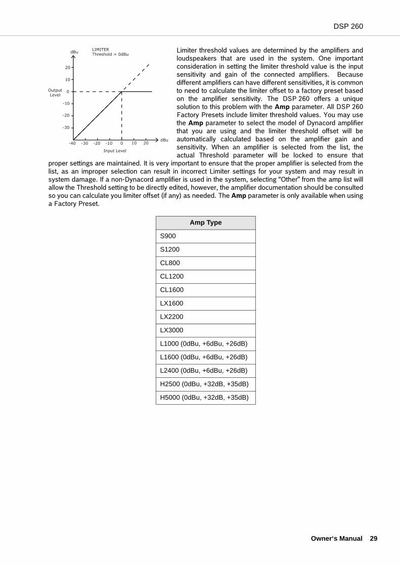
Limiter threshold values are determined by the amplifiers andloudspeakers that are used in the system. One importantconsideration in setting the limiter threshold value is the inputsensitivity and gain of the connected amplifiers. Becausedifferent amplifiers can have different sensitivities, it is commonto need to calculate the limiter offset to a factory preset basedon the amplifier sensitivity. The DSP 260 offers a uniquesolution to this problem with the Amp parameter. All DSP 260Factory Presets include limiter threshold values. You may usethe Amp parameter to select the model of Dynacord amplifierthat you are using and the limiter threshold offset will beautomatically calculated based on the amplifier gain andsensitivity. When an amplifier is selected from the list, theactual Threshold parameter will be locked to ensure that
proper settings are maintained. It is very important to ensure that the proper amplifier is selected from thelist, as an improper selection can result in incorrect Limiter settings for your system and may result insystem damage. If a non-Dynacord amplifier is used in the system, selecting “Other” from the amp list willallow the Threshold setting to be directly edited, however, the amplifier documentation should be consultedso you can calculate you limiter offset (if any) as needed. The Amp parameter is only available when usinga Factory Preset.
Amp Type
S900
S1200
CL800
CL1200
CL1600
LX1600
LX2200
LX3000
L1000 (0dBu, +6dBu, +26dB)
L1600 (0dBu, +6dBu, +26dB)
L2400 (0dBu, +6dBu, +26dB)
H2500 (0dBu, +32dB, +35dB)
H5000 (0dBu, +32dB, +35dB)
Owner‘s Manual 29
DSP 260
30 O
6 Setup
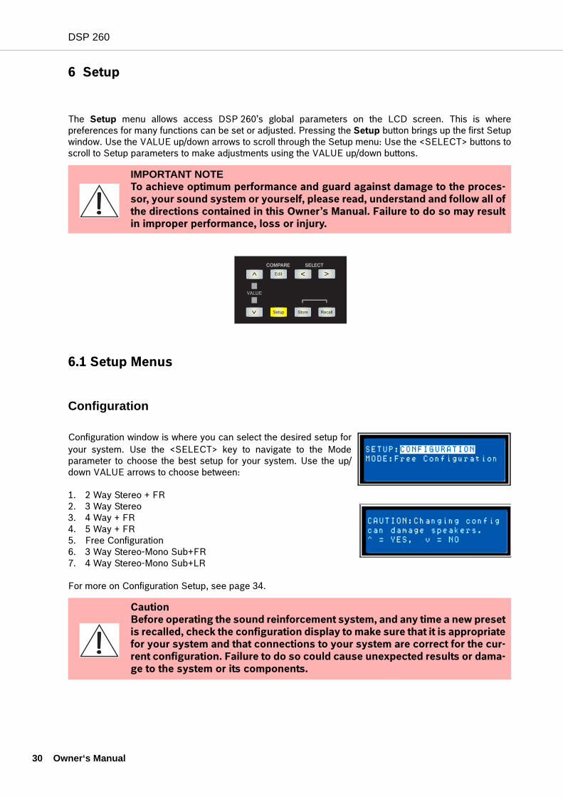
The Setup menu allows access DSP 260’s global parameters on the LCD screen. This is wherepreferences for many functions can be set or adjusted. Pressing the Setup button brings up the first Setupwindow. Use the VALUE up/down arrows to scroll through the Setup menu: Use the <SELECT> buttons toscroll to Setup parameters to make adjustments using the VALUE up/down buttons.
6.1 Setup Menus
Configuration
Configuration window is where you can select the desired setup foryour system. Use the <SELECT> key to navigate to the Modeparameter to choose the best setup for your system. Use the up/down VALUE arrows to choose between:
1. 2 Way Stereo + FR2. 3 Way Stereo3. 4 Way + FR4. 5 Way + FR5. Free Configuration6. 3 Way Stereo-Mono Sub+FR7. 4 Way Stereo-Mono Sub+LR
For more on Configuration Setup, see page 34.
IMPORTANT NOTETo achieve optimum performance and guard against damage to the proces-sor, your sound system or yourself, please read, understand and follow all ofthe directions contained in this Owner’s Manual. Failure to do so may resultin improper performance, loss or injury.
Caution Before operating the sound reinforcement system, and any time a new presetis recalled, check the configuration display to make sure that it is appropriatefor your system and that connections to your system are correct for the cur-rent configuration. Failure to do so could cause unexpected results or dama-ge to the system or its components.
wner‘s Manual
DSP 260
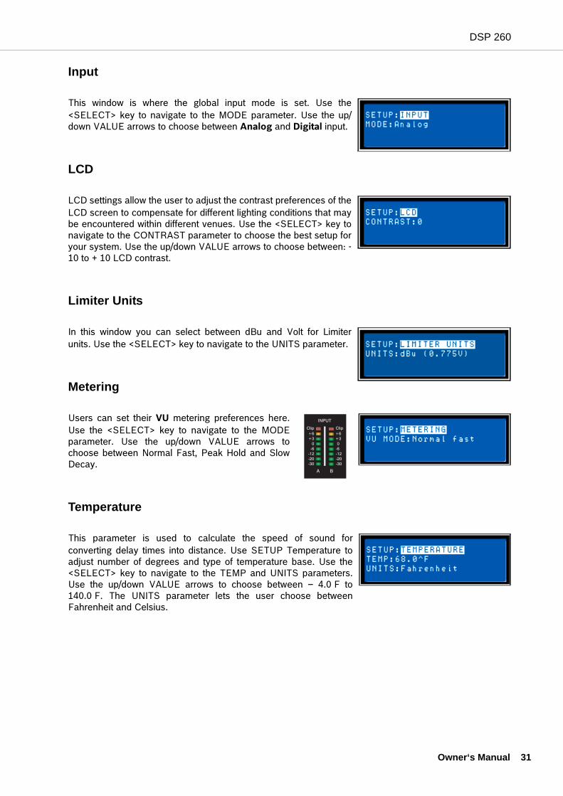
Input
This window is where the global input mode is set. Use the<SELECT> key to navigate to the MODE parameter. Use the up/down VALUE arrows to choose between Analog and Digital input.
LCD
LCD settings allow the user to adjust the contrast preferences of theLCD screen to compensate for different lighting conditions that maybe encountered within different venues. Use the <SELECT> key tonavigate to the CONTRAST parameter to choose the best setup foryour system. Use the up/down VALUE arrows to choose between: -10 to + 10 LCD contrast.
Limiter Units
In this window you can select between dBu and Volt for Limiterunits. Use the <SELECT> key to navigate to the UNITS parameter.
Metering
Users can set their VU metering preferences here.Use the <SELECT> key to navigate to the MODEparameter. Use the up/down VALUE arrows tochoose between Normal Fast, Peak Hold and SlowDecay.
Temperature
This parameter is used to calculate the speed of sound forconverting delay times into distance. Use SETUP Temperature toadjust number of degrees and type of temperature base. Use the<SELECT> key to navigate to the TEMP and UNITS parameters.Use the up/down VALUE arrows to choose between – 4.0 F to140.0 F. The UNITS parameter lets the user choose betweenFahrenheit and Celsius.
Owner‘s Manual 31
DSP 260
32 O
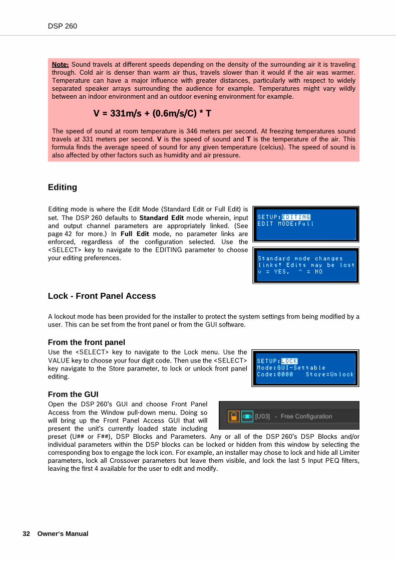
Editing
Editing mode is where the Edit Mode (Standard Edit or Full Edit) isset. The DSP 260 defaults to Standard Edit mode wherein, inputand output channel parameters are appropriately linked. (Seepage 42 for more.) In Full Edit mode, no parameter links areenforced, regardless of the configuration selected. Use the<SELECT> key to navigate to the EDITING parameter to chooseyour editing preferences.
Lock - Front Panel Access
A lockout mode has been provided for the installer to protect the system settings from being modified by auser. This can be set from the front panel or from the GUI software.
From the front panelUse the <SELECT> key to navigate to the Lock menu. Use theVALUE key to choose your four digit code. Then use the <SELECT>key navigate to the Store parameter, to lock or unlock front panelediting.
From the GUIOpen the DSP 260’s GUI and choose Front PanelAccess from the Window pull-down menu. Doing sowill bring up the Front Panel Access GUI that willpresent the unit’s currently loaded state includingpreset (U## or F##), DSP Blocks and Parameters. Any or all of the DSP 260’s DSP Blocks and/orindividual parameters within the DSP blocks can be locked or hidden from this window by selecting thecorresponding box to engage the lock icon. For example, an installer may chose to lock and hide all Limiterparameters, lock all Crossover parameters but leave them visible, and lock the last 5 Input PEQ filters,leaving the first 4 available for the user to edit and modify.
Note: Sound travels at different speeds depending on the density of the surrounding air it is travelingthrough. Cold air is denser than warm air thus, travels slower than it would if the air was warmer.Temperature can have a major influence with greater distances, particularly with respect to widelyseparated speaker arrays surrounding the audience for example. Temperatures might vary wildlybetween an indoor environment and an outdoor evening environment for example.
V = 331m/s + (0.6m/s/C) * T
The speed of sound at room temperature is 346 meters per second. At freezing temperatures soundtravels at 331 meters per second. V is the speed of sound and T is the temperature of the air. Thisformula finds the average speed of sound for any given temperature (celcius). The speed of sound isalso affected by other factors such as humidity and air pressure.
wner‘s Manual
DSP 260
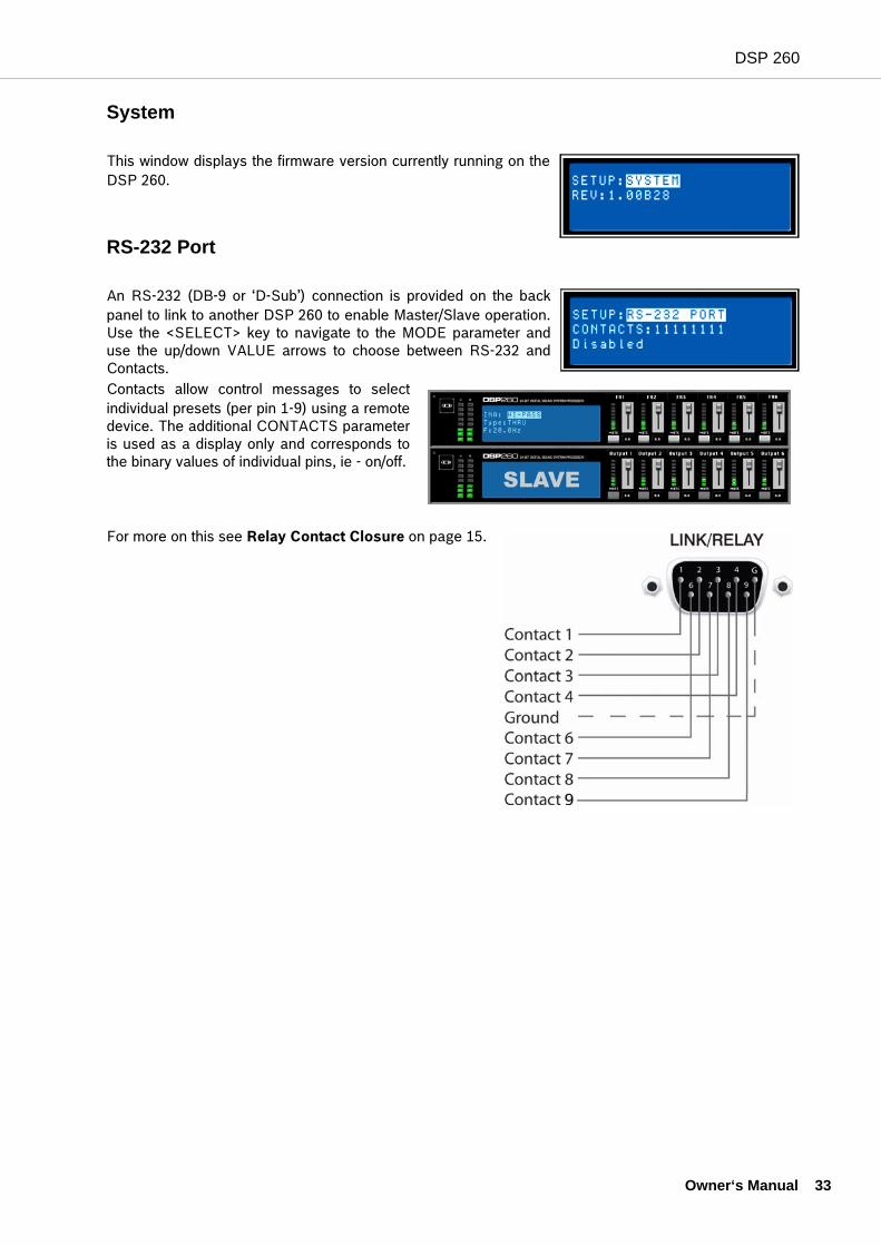
System
This window displays the firmware version currently running on theDSP 260.
RS-232 Port
An RS-232 (DB-9 or ‘D-Sub’) connection is provided on the backpanel to link to another DSP 260 to enable Master/Slave operation.Use the <SELECT> key to navigate to the MODE parameter anduse the up/down VALUE arrows to choose between RS-232 andContacts.Contacts allow control messages to selectindividual presets (per pin 1-9) using a remotedevice. The additional CONTACTS parameteris used as a display only and corresponds tothe binary values of individual pins, ie - on/off.
For more on this see Relay Contact Closure on page 15.
Owner‘s Manual 33
DSP 260
34 O
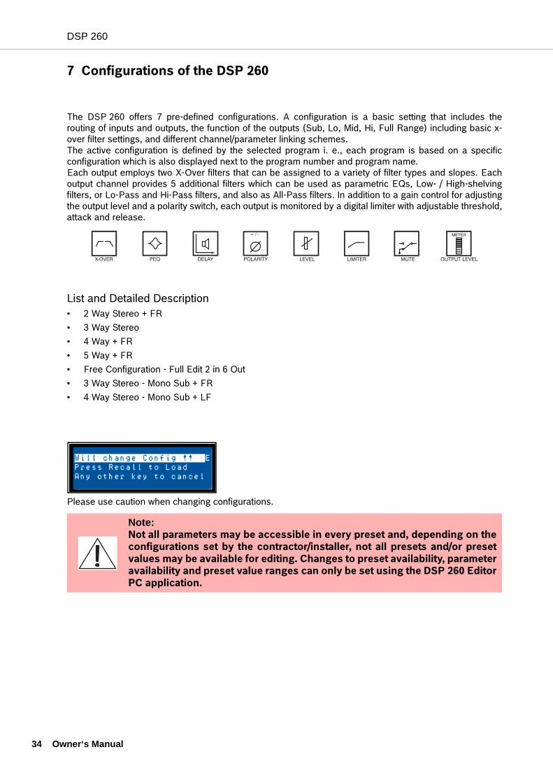
7 Configurations of the DSP 260
The DSP 260 offers 7 pre-defined configurations. A configuration is a basic setting that includes therouting of inputs and outputs, the function of the outputs (Sub, Lo, Mid, Hi, Full Range) including basic x-over filter settings, and different channel/parameter linking schemes.The active configuration is defined by the selected program i. e., each program is based on a specificconfiguration which is also displayed next to the program number and program name.Each output employs two X-Over filters that can be assigned to a variety of filter types and slopes. Eachoutput channel provides 5 additional filters which can be used as parametric EQs, Low- / High-shelvingfilters, or Lo-Pass and Hi-Pass filters, and also as All-Pass filters. In addition to a gain control for adjustingthe output level and a polarity switch, each output is monitored by a digital limiter with adjustable threshold,attack and release.
List and Detailed Description• 2 Way Stereo + FR• 3 Way Stereo• 4 Way + FR• 5 Way + FR• Free Configuration - Full Edit 2 in 6 Out• 3 Way Stereo - Mono Sub + FR• 4 Way Stereo - Mono Sub + LF
Please use caution when changing configurations.
Note: Not all parameters may be accessible in every preset and, depending on theconfigurations set by the contractor/installer, not all presets and/or presetvalues may be available for editing. Changes to preset availability, parameteravailability and preset value ranges can only be set using the DSP 260 EditorPC application.
wner‘s Manual
DSP 260
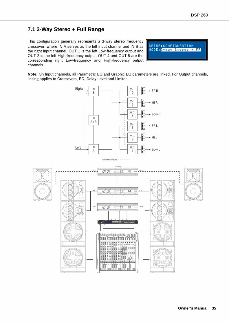
7.1 2-Way Stereo + Full Range
This configuration generally represents a 2-way stereo frequencycrossover, where IN A serves as the left input channel and IN B asthe right input channel. OUT 1 is the left Low-frequency output andOUT 2 is the left High-frequency output. OUT 4 and OUT 5 are thecorresponding right Low-frequency and High-frequency outputchannels
Note: On Input channels, all Parametric EQ and Graphic EQ parameters are linked. For Output channels,linking applies to Crossovers, EQ, Delay Level and Limiter.
Owner‘s Manual 35
DSP 260
36 O
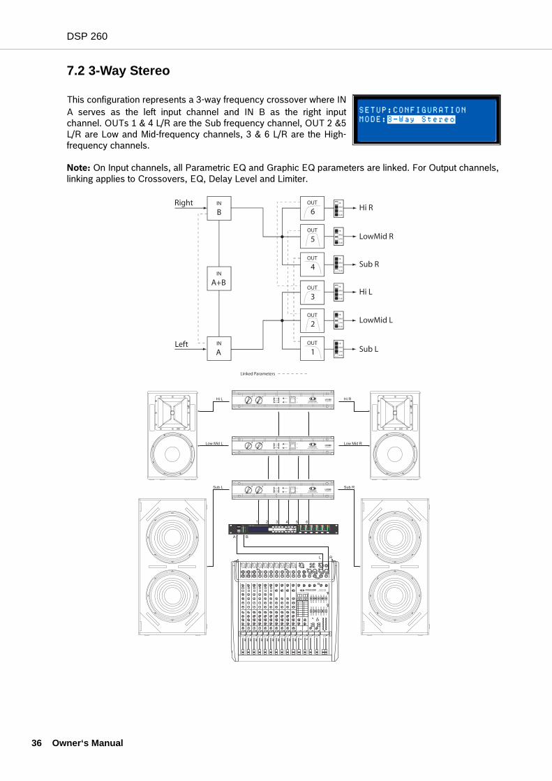
7.2 3-Way Stereo
This configuration represents a 3-way frequency crossover where INA serves as the left input channel and IN B as the right inputchannel. OUTs 1 & 4 L/R are the Sub frequency channel, OUT 2 &5L/R are Low and Mid-frequency channels, 3 & 6 L/R are the High-frequency channels.
Note: On Input channels, all Parametric EQ and Graphic EQ parameters are linked. For Output channels, linking applies to Crossovers, EQ, Delay Level and Limiter.
wner‘s Manual
DSP 260
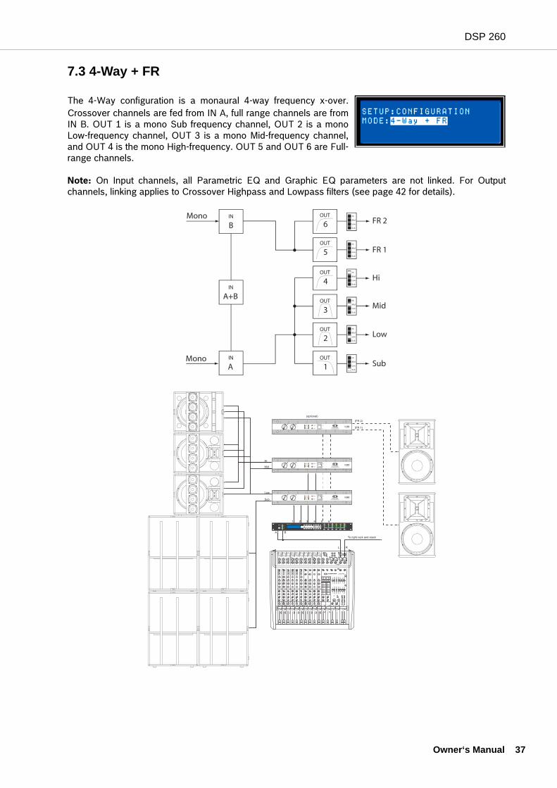
7.3 4-Way + FR
The 4-Way configuration is a monaural 4-way frequency x-over.Crossover channels are fed from IN A, full range channels are fromIN B. OUT 1 is a mono Sub frequency channel, OUT 2 is a monoLow-frequency channel, OUT 3 is a mono Mid-frequency channel,and OUT 4 is the mono High-frequency. OUT 5 and OUT 6 are Full-range channels.
Note: On Input channels, all Parametric EQ and Graphic EQ parameters are not linked. For Outputchannels, linking applies to Crossover Highpass and Lowpass filters (see page 42 for details).
Owner‘s Manual 37
DSP 260
38 O
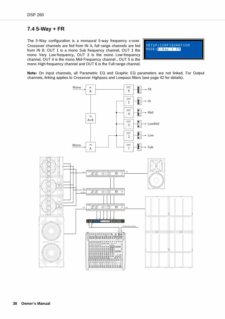
7.4 5-Way + FR
The 5-Way configuration is a monaural 5-way frequency x-over.Crossover channels are fed from IN A, full range channels are fedfrom IN B. OUT 1 is a mono Sub frequency channel, OUT 2 themono Very Low-frequency, OUT 3 is the mono Low-frequencychannel, OUT 4 is the mono Mid-Frequency channel , OUT 5 is themono High-frequency channel and OUT 6 is the Full-range channel.
Note: On Input channels, all Parametric EQ and Graphic EQ parameters are not linked. For Outputchannels, linking applies to Crossover Highpass and Lowpass filters (see page 42 for details).
wner‘s Manual
DSP 260
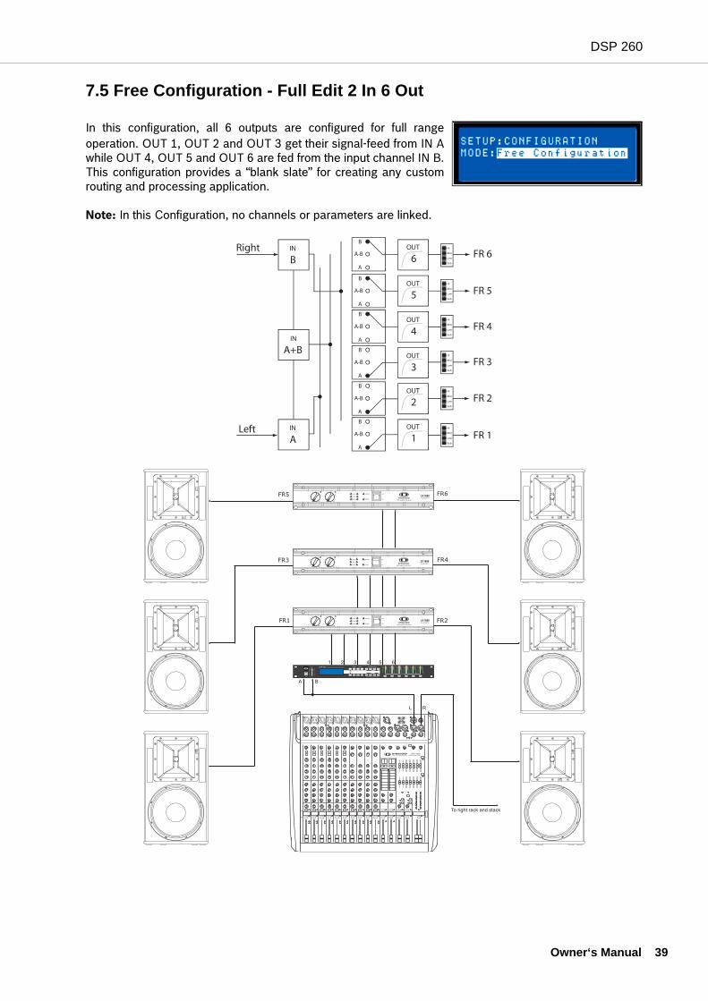
7.5 Free Configuration - Full Edit 2 In 6 Out
In this configuration, all 6 outputs are configured for full rangeoperation. OUT 1, OUT 2 and OUT 3 get their signal-feed from IN Awhile OUT 4, OUT 5 and OUT 6 are fed from the input channel IN B.This configuration provides a “blank slate” for creating any customrouting and processing application.
Note: In this Configuration, no channels or parameters are linked.
FR6
FR4
FR2
FR5
FR3
FR1
Owner‘s Manual 39
DSP 260
40 O
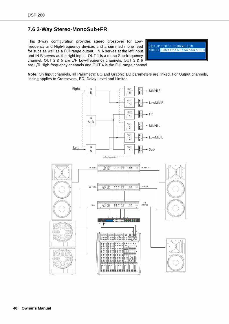
7.6 3-Way Stereo-MonoSub+FR
This 3-way configuration provides stereo crossover for Low-frequency and High-frequency devices and a summed mono feedfor subs as well as a Full-range output. IN A serves at the left inputand IN B serves as the right input. OUT 1 is a mono Sub-frequencychannel, OUT 2 & 5 are L/R Low-frequency channels, OUT 3 & 6are L/R High-frequency channels and OUT 4 is the Full-range channel.
Note: On Input channels, all Parametric EQ and Graphic EQ parameters are linked. For Output channels,linking applies to Crossovers, EQ, Delay Level and Limiter.
FR
(Mono)
Hi Mid L
Lo Mid L
Sub
Hi Mid R
Lo Mid R
wner‘s Manual
DSP 260
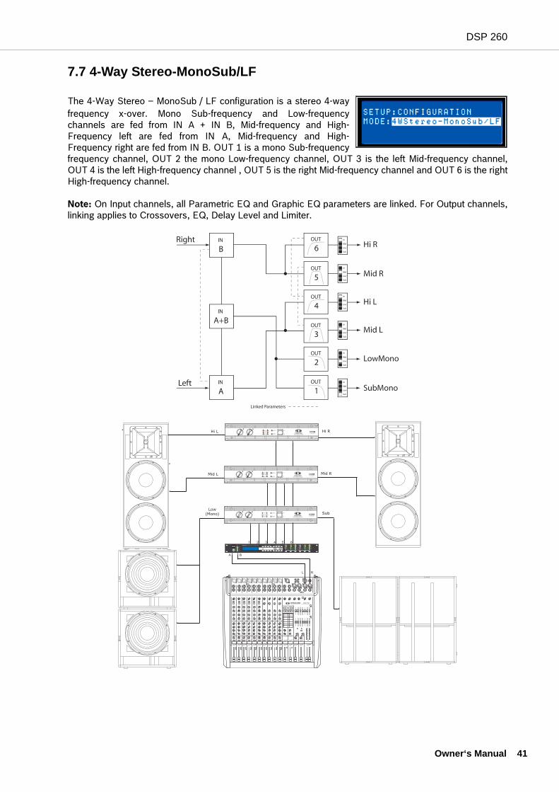
7.7 4-Way Stereo-MonoSub/LF
The 4-Way Stereo – MonoSub / LF configuration is a stereo 4-wayfrequency x-over. Mono Sub-frequency and Low-frequencychannels are fed from IN A + IN B, Mid-frequency and High-Frequency left are fed from IN A, Mid-frequency and High-Frequency right are fed from IN B. OUT 1 is a mono Sub-frequencyfrequency channel, OUT 2 the mono Low-frequency channel, OUT 3 is the left Mid-frequency channel,OUT 4 is the left High-frequency channel , OUT 5 is the right Mid-frequency channel and OUT 6 is the rightHigh-frequency channel.
Note: On Input channels, all Parametric EQ and Graphic EQ parameters are linked. For Output channels,linking applies to Crossovers, EQ, Delay Level and Limiter.
Low
(Mono)
Hi L
Mid L
Sub
Hi R
Mid R
Owner‘s Manual 41
DSP 260
42 O
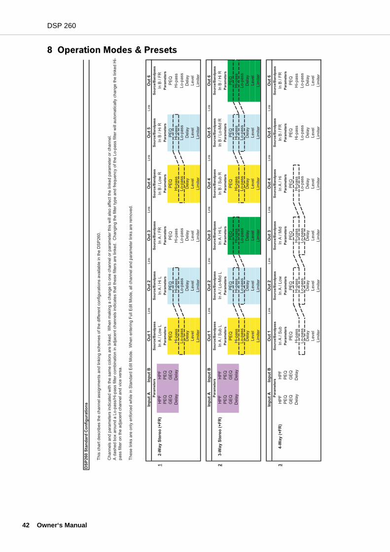
8 Operation Modes & Presets
DS
P2
60
Sta
nd
ard
Co
nfi
gu
rati
on
s Inp
ut
AIn
pu
t B
Ou
t 1
Lin
kO
ut
2L
ink
Ou
t 3
Lin
kO
ut
4L
ink
Ou
t 5
Lin
kO
ut
6
So
urc
e/B
an
dp
as
sS
ou
rce
/Ba
nd
pa
ss
So
urc
e/B
an
dp
as
sS
ou
rce
/Ba
nd
pa
ss
So
urc
e/B
an
dp
as
sS
ou
rce
/Ba
nd
pa
ss
12
-Wa
y S
tere
o (
+F
R)
HP
FH
PF
In A
/ L
ow
LIn
A /
Hi L
In A
/ F
RIn
B /
Lo
w R
In B
/ H
i R
In B
/ F
R
PE
QP
EQ
Pa
ram
ete
rsP
ara
me
ters
Pa
ram
ete
rsP
ara
me
ters
Pa
ram
ete
rsP
ara
me
ters
GE
QG
EQ
PE
QP
EQ
PE
QP
EQ
PE
QP
EQ
De
lay
De
lay
Hi-p
ass
Hi-p
ass
Hi-p
ass
Hi-p
ass
Hi-p
ass
Hi-p
ass
Lo
-pa
ss
Lo
-pa
ss
Lo
-pa
ss
Lo
-pa
ss
Lo
-pa
ss
Lo
-pa
ss
De
lay
De
lay
De
lay
De
lay
De
lay
De
lay
Le
ve
lL
eve
lL
eve
lL
eve
lL
eve
lL
eve
l
Lim
ite
rL
imite
rL
imite
rL
imite
rL
imite
rL
imite
r
Inp
ut
AIn
pu
t B
Ou
t 1
Lin
kO
ut
2L
ink
Ou
t 3
Lin
kO
ut
4L
ink
Ou
t 5
Lin
kO
ut
6
So
urc
e/B
an
dp
as
sS
ou
rce
/Ba
nd
pa
ss
So
urc
e/B
an
dp
as
sS
ou
rce
/Ba
nd
pa
ss
So
urc
e/B
an
dp
as
sS
ou
rce
/Ba
nd
pa
ss
23
-Wa
y S
tere
o (
+F
R)
HP
FH
PF
In A
/ S
ub
LIn
A /
Lo
-Mid
LIn
A /
Hi L
In B
/ S
ub
RIn
B /
Lo
-Mid
RIn
B /
Hi R
PE
QP
EQ
Pa
ram
ete
rsP
ara
me
ters
Pa
ram
ete
rsP
ara
me
ters
Pa
ram
ete
rsP
ara
me
ters
GE
QG
EQ
PE
QP
EQ
PE
QP
EQ
PE
QP
EQ
De
lay
De
lay
Hi-p
ass
Hi-p
ass
Hi-p
ass
Hi-p
ass
Hi-p
ass
Hi-p
ass
Lo
-pa
ss
Lo
-pa
ss
Lo
-pa
ss
Lo
-pa
ss
Lo
-pa
ss
Lo
-pa
ss
De
lay
De
lay
De
lay
De
lay
De
lay
De
lay
Le
ve
lL
eve
lL
eve
lL
eve
lL
eve
lL
eve
l
Lim
ite
rL
imite
rL
imite
rL
imite
rL
imite
rL
imite
r
Inp
ut
AIn
pu
t B
Ou
t 1
Lin
kO
ut
2L
ink
Ou
t 3
Lin
kO
ut
4L
ink
Ou
t 5
Lin
kO
ut
6
So
urc
e/B
an
dp
as
sS
ou
rce
/Ba
nd
pa
ss
So
urc
e/B
an
dp
as
sS
ou
rce
/Ba
nd
pa
ss
So
urc
e/B
an
dp
as
sS
ou
rce
/Ba
nd
pa
ss
34
-Wa
y (
+F
R)
HP
FH
PF
In A
/ S
ub
In A
/ L
ow
In A
/ M
idIn
A /
Hi
In B
/ F
RIn
B /
FR
PE
QP
EQ
Pa
ram
ete
rsP
ara
me
ters
Pa
ram
ete
rsP
ara
me
ters
Pa
ram
ete
rsP
ara
me
ters
GE
QG
EQ
PE
QP
EQ
PE
QP
EQ
PE
QP
EQ
De
lay
De
lay
Hi-p
ass
Hi-p
ass
Hi-p
ass
Hi-p
ass
Hi-p
ass
Hi-p
ass
Lo
-pa
ss
Lo
-pa
ss
Lo
-pa
ss
Lo
-pa
ss
Lo
-pa
ss
Lo
-pa
ss
De
lay
De
lay
De
lay
De
lay
De
lay
De
lay
Le
ve
lL
eve
lL
eve
lL
eve
lL
eve
lL
eve
l
Lim
ite
rL
imite
rL
imite
rL
imite
rL
imite
rL
imite
r
Th
is c
ha
rt d
escrib
es t
he
ch
an
ne
l a
ssig
nm
en
ts a
nd
lin
kin
g s
ch
em
es o
f th
e d
iffe
ren
t co
nfig
ura
tio
ns a
va
ilab
le in
th
e D
SP
26
0.
Ch
an
ne
ls a
nd
pa
ram
ete
rs in
dic
ate
d w
ith
th
e s
am
e c
olo
rs a
re lin
ke
d.
Wh
en
ma
kin
g a
ch
an
ge
to
on
e c
ha
nn
el o
r p
ara
me
ter
this
will
als
o a
ffe
ct
the
lin
ke
d p
ara
me
ter
or
ch
an
ne
l.
A d
ash
ed
bo
x a
rou
nd
a L
o-p
ass/H
i-p
ass f
ilte
r co
mb
ina
tio
n in
ad
jace
nt
ch
an
ne
ls in
dic
ate
s t
ha
t th
ese
filt
ers
are
lin
ke
d.
Ch
an
gin
g t
he
filt
er
typ
e a
nd
fre
qu
en
cy o
f th
e L
o-p
ass f
ilte
r w
ill a
uto
ma
tica
lly c
ha
ng
e t
he
lin
ke
d H
i-
pa
ss f
ilte
r o
n t
he
ad
jace
nt
ch
an
ne
l a
nd
vic
e v
ers
a.
Th
ese
lin
ks a
re o
nly
en
forc
ed
wh
ile in
Sta
nd
ard
Ed
it M
od
e.
Wh
en
en
terin
g F
ull
Ed
it M
od
e,
all
ch
an
ne
l a
nd
pa
ram
ete
r lin
ks a
re r
em
ove
d.
Pa
ram
ete
rs
Pa
ram
ete
rs
Pa
ram
ete
rs
wner‘s Manual
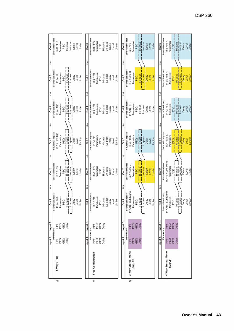
DSP 260
Inp
ut
AIn
pu
t B
Ou
t 1
Lin
kO
ut
2Lin
kO
ut
3Lin
kO
ut
4Lin
kO
ut
5Lin
kO
ut
6
So
urc
e/B
an
dp
ass
So
urc
e/B
an
dp
ass
So
urc
e/B
an
dp
ass
So
urc
e/B
an
dp
ass
So
urc
e/B
an
dp
ass
So
urc
e/B
an
dp
ass
45-W
ay (
+F
R)
HP
FH
PF
In A
/ S
ub
In A
/ L
ow
In A
/ L
ow
-Mid
In A
/ M
idIn
A / H
iIn
B / F
R
PE
QP
EQ
Para
mete
rsP
ara
mete
rsP
ara
mete
rsP
ara
mete
rsP
ara
mete
rsP
ara
mete
rs
GE
QG
EQ
PE
QP
EQ
PE
QP
EQ
PE
QP
EQ
Dela
yD
ela
yH
i-pass
Hi-pass
Hi-pass
Hi-pass
Hi-pass
Hi-pass
Lo-p
ass
Lo-p
ass
Lo-p
ass
Lo-p
ass
Lo-p
ass
Lo-p
ass
Dela
yD
ela
yD
ela
yD
ela
yD
ela
yD
ela
y
Level
Level
Level
Level
Level
Level
Lim
iter
Lim
iter
Lim
iter
Lim
iter
Lim
iter
Lim
iter
Inp
ut
AIn
pu
t B
Ou
t 1
Lin
kO
ut
2Lin
kO
ut
3Lin
kO
ut
4Lin
kO
ut
5Lin
kO
ut
6
So
urc
e/B
an
dp
ass
So
urc
e/B
an
dp
ass
So
urc
e/B
an
dp
ass
So
urc
e/B
an
dp
ass
So
urc
e/B
an
dp
ass
So
urc
e/B
an
dp
ass
5F
ree C
on
fig
ura
tio
nH
PF
HP
FIn
A / F
RIn
A / F
RIn
A / F
RIn
B / F
RIn
B / F
RIn
B / F
R
PE
QP
EQ
Para
mete
rsP
ara
mete
rsP
ara
mete
rsP
ara
mete
rsP
ara
mete
rsP
ara
mete
rs
GE
QG
EQ
PE
QP
EQ
PE
QP
EQ
PE
QP
EQ
Dela
yD
ela
yH
i-pass
Hi-pass
Hi-pass
Hi-pass
Hi-pass
Hi-pass
Lo-p
ass
Lo-p
ass
Lo-p
ass
Lo-p
ass
Lo-p
ass
Lo-p
ass
Dela
yD
ela
yD
ela
yD
ela
yD
ela
yD
ela
y
Level
Level
Level
Level
Level
Level
Lim
iter
Lim
iter
Lim
iter
Lim
iter
Lim
iter
Lim
iter
Inp
ut
AIn
pu
t B
Ou
t 1
Lin
kO
ut
2Lin
kO
ut
3Lin
kO
ut
4Lin
kO
ut
5Lin
kO
ut
6
So
urc
e/B
an
dp
ass
So
urc
e/B
an
dp
ass
So
urc
e/B
an
dp
ass
So
urc
e/B
an
dp
ass
So
urc
e/B
an
dp
ass
So
urc
e/B
an
dp
ass
6H
PF
HP
FIn
A+
B / S
ub M
ono
In A
/ L
ow
LIn
A / H
i L
In A
+B
/ F
RIn
B / L
ow
RIn
B / H
i R
PE
QP
EQ
Para
mete
rsP
ara
mete
rsP
ara
mete
rsP
ara
mete
rsP
ara
mete
rsP
ara
mete
rs
GE
QG
EQ
PE
QP
EQ
PE
QP
EQ
PE
QP
EQ
Dela
yD
ela
yH
i-pass
Hi-pass
Hi-pass
Hi-pass
Hi-pass
Hi-pass
Lo-p
ass
Lo-p
ass
Lo-p
ass
Lo-p
ass
Lo-p
ass
Lo-p
ass
Dela
yD
ela
yD
ela
yD
ela
yD
ela
yD
ela
y
Level
Level
Level
Level
Level
Level
Lim
iter
Lim
iter
Lim
iter
Lim
iter
Lim
iter
Lim
iter
Inp
ut
AIn
pu
t B
Ou
t 1
Lin
kO
ut
2Lin
kO
ut
3Lin
kO
ut
4Lin
kO
ut
5Lin
kO
ut
6
So
urc
e/B
an
dp
ass
So
urc
e/B
an
dp
ass
So
urc
e/B
an
dp
ass
So
urc
e/B
an
dp
ass
So
urc
e/B
an
dp
ass
So
urc
e/B
an
dp
ass
7H
PF
HP
FIn
A+
B / S
ub M
ono
In A
+B
/ L
ow
Mono
In A
/ M
id L
In A
/ H
i L
In B
/ M
id R
In B
/ H
i R
PE
QP
EQ
Para
mete
rsP
ara
mete
rsP
ara
mete
rsP
ara
mete
rsP
ara
mete
rsP
ara
mete
rs
GE
QG
EQ
PE
QP
EQ
PE
QP
EQ
PE
QP
EQ
Dela
yD
ela
yH
i-pass
Hi-pass
Hi-pass
Hi-pass
Hi-pass
Hi-pass
Lo-p
ass
Lo-p
ass
Lo-p
ass
Lo-p
ass
Lo-p
ass
Lo-p
ass
Dela
yD
ela
yD
ela
yD
ela
yD
ela
yD
ela
y
Level
Level
Level
Level
Level
Level
Lim
iter
Lim
iter
Lim
iter
Lim
iter
Lim
iter
Lim
iter
4-W
ay S
tere
o, M
on
o
Su
b/L
F
Para
mete
rs
Para
mete
rs
Para
mete
rs
Para
mete
rs
3-W
ay S
tere
o, M
on
o
Su
b+
FR
Owner‘s Manual 43
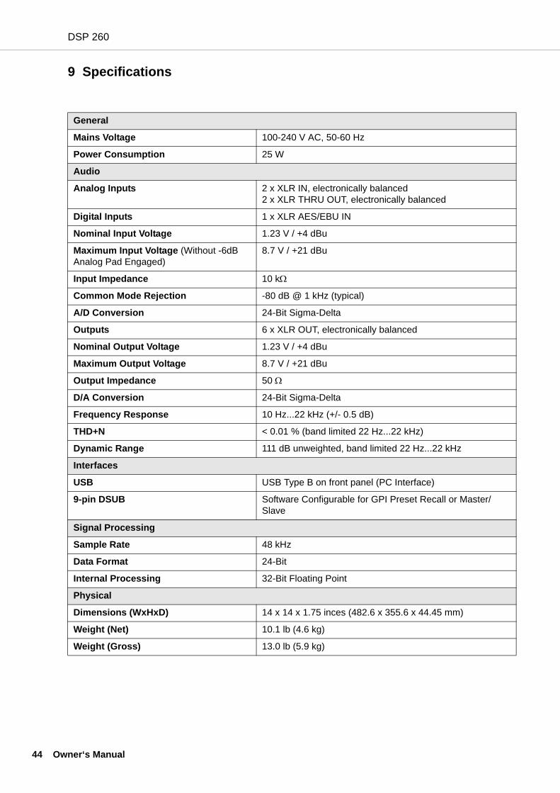
DSP 260
44 O
9 Specifications
General
Mains Voltage 100-240 V AC, 50-60 Hz
Power Consumption 25 W
Audio
Analog Inputs 2 x XLR IN, electronically balanced2 x XLR THRU OUT, electronically balanced
Digital Inputs 1 x XLR AES/EBU IN
Nominal Input Voltage 1.23 V / +4 dBu
Maximum Input Voltage (Without -6dB Analog Pad Engaged)
8.7 V / +21 dBu
Input Impedance 10 kΩ
Common Mode Rejection -80 dB @ 1 kHz (typical)
A/D Conversion 24-Bit Sigma-Delta
Outputs 6 x XLR OUT, electronically balanced
Nominal Output Voltage 1.23 V / +4 dBu
Maximum Output Voltage 8.7 V / +21 dBu
Output Impedance 50 Ω
D/A Conversion 24-Bit Sigma-Delta
Frequency Response 10 Hz...22 kHz (+/- 0.5 dB)
THD+N < 0.01 % (band limited 22 Hz...22 kHz)
Dynamic Range 111 dB unweighted, band limited 22 Hz...22 kHz
Interfaces
USB USB Type B on front panel (PC Interface)
9-pin DSUB Software Configurable for GPI Preset Recall or Master/Slave
Signal Processing
Sample Rate 48 kHz
Data Format 24-Bit
Internal Processing 32-Bit Floating Point
Physical
Dimensions (WxHxD) 14 x 14 x 1.75 inces (482.6 x 355.6 x 44.45 mm)
Weight (Net) 10.1 lb (4.6 kg)
Weight (Gross) 13.0 lb (5.9 kg)
wner‘s Manual
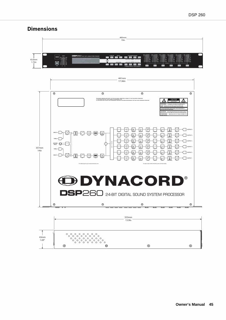
DSP 260
Dimensions483mm
19in
43.6mm1.72in
AVIS:
WARNING:
CAUTION:
ATTENTION:
441mm17.36in
357mm14in
353mm13.9in
43mm1.69”
Owner‘s Manual 45
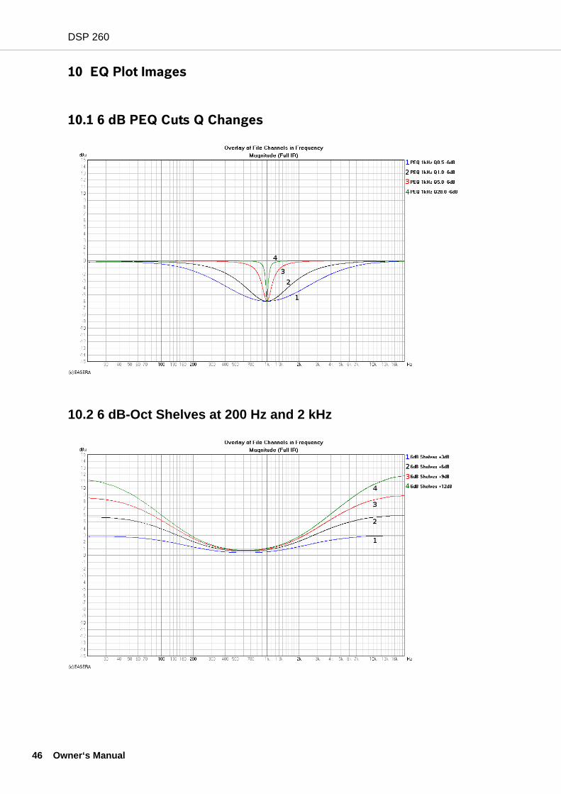
DSP 260
46 O
10 EQ Plot Images
10.1 6 dB PEQ Cuts Q Changes
10.2 6 dB-Oct Shelves at 200 Hz and 2 kHz
wner‘s Manual
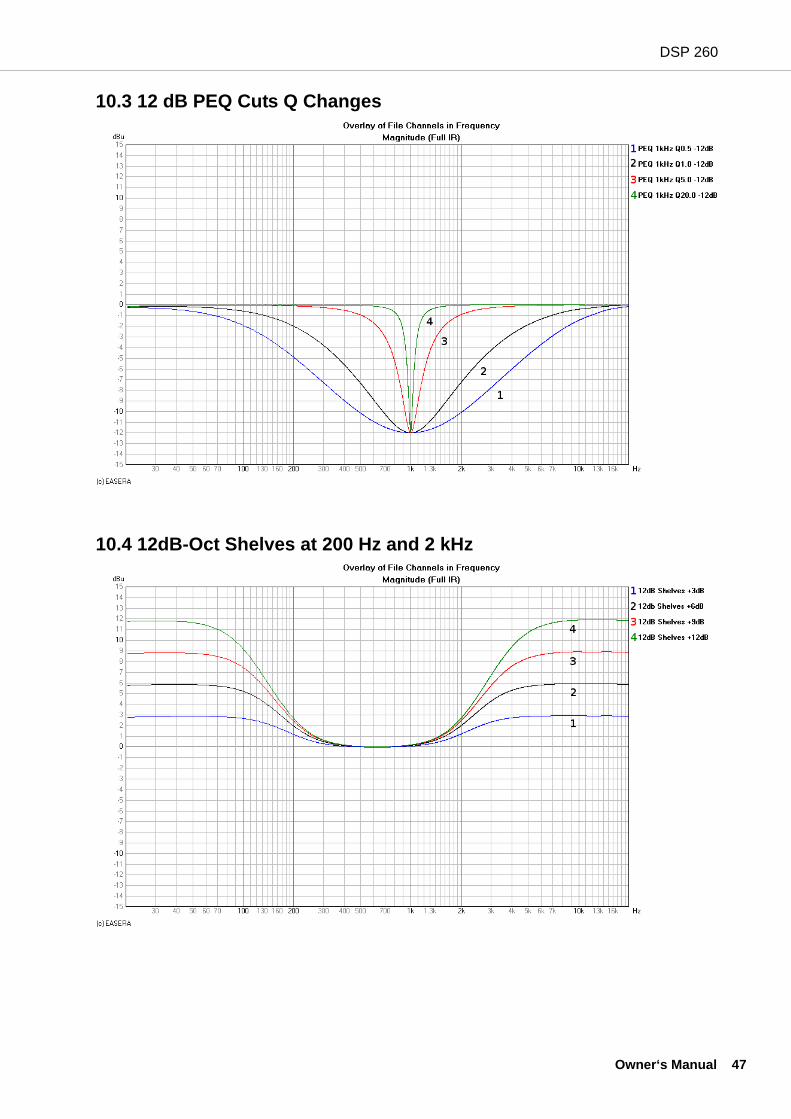
DSP 260
10.3 12 dB PEQ Cuts Q Changes
10.4 12dB-Oct Shelves at 200 Hz and 2 kHz
Owner‘s Manual 47
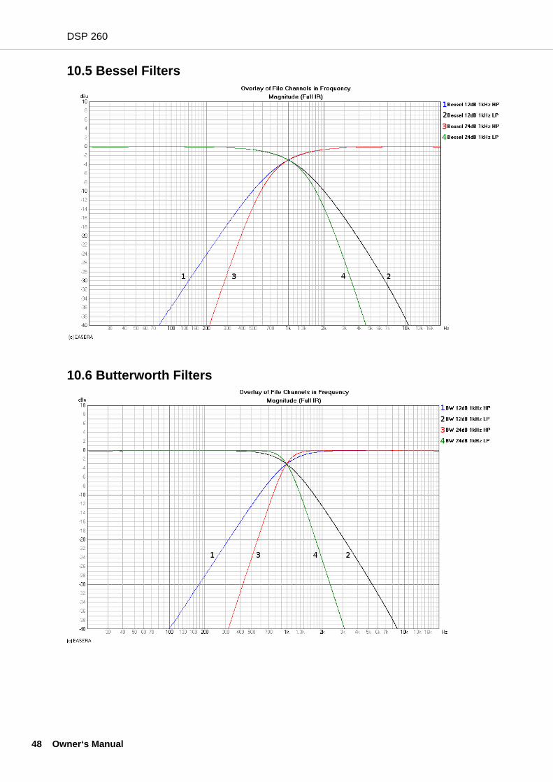
DSP 260
48 O
10.5 Bessel Filters
10.6 Butterworth Filters
wner‘s Manual
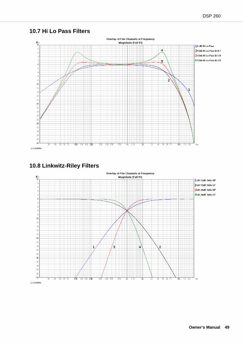
DSP 260
10.7 Hi Lo Pass Filters
10.8 Linkwitz-Riley Filters
Owner‘s Manual 49
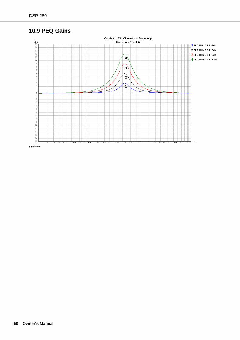
DSP 260
50 O
10.9 PEQ Gains
wner‘s Manual

DSP 260
Owner‘s Manual 51
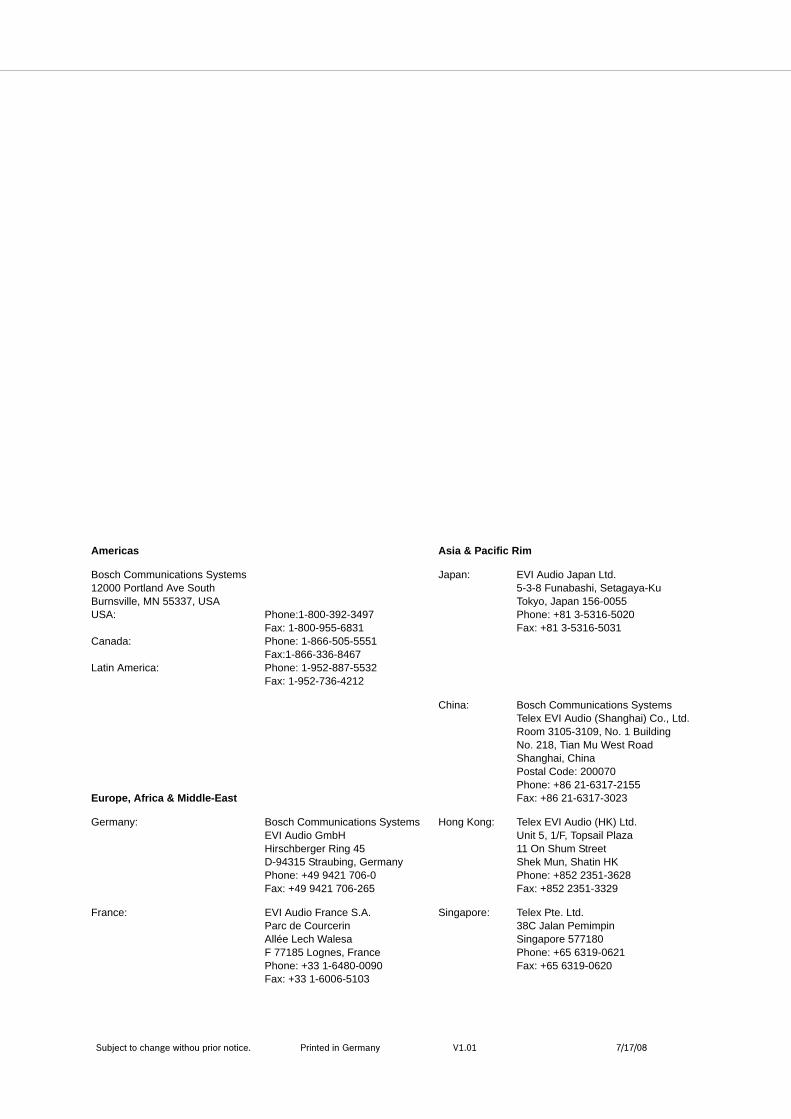
Subject to change withou prior notice. Printed in Germany V1.01 7/17/08
Americas Asia & Pacific Rim
Bosch Communications Systems12000 Portland Ave SouthBurnsville, MN 55337, USAUSA:
Canada:
Latin America:
Phone:1-800-392-3497Fax: 1-800-955-6831Phone: 1-866-505-5551Fax:1-866-336-8467Phone: 1-952-887-5532Fax: 1-952-736-4212
Japan: EVI Audio Japan Ltd.5-3-8 Funabashi, Setagaya-KuTokyo, Japan 156-0055Phone: +81 3-5316-5020Fax: +81 3-5316-5031
Europe, Africa & Middle-East
China: Bosch Communications SystemsTelex EVI Audio (Shanghai) Co., Ltd.Room 3105-3109, No. 1 BuildingNo. 218, Tian Mu West RoadShanghai, ChinaPostal Code: 200070Phone: +86 21-6317-2155Fax: +86 21-6317-3023
Germany: Bosch Communications SystemsEVI Audio GmbHHirschberger Ring 45D-94315 Straubing, GermanyPhone: +49 9421 706-0Fax: +49 9421 706-265
Hong Kong: Telex EVI Audio (HK) Ltd.Unit 5, 1/F, Topsail Plaza11 On Shum StreetShek Mun, Shatin HKPhone: +852 2351-3628Fax: +852 2351-3329
France: EVI Audio France S.A. Parc de CourcerinAllée Lech Walesa F 77185 Lognes, FrancePhone: +33 1-6480-0090Fax: +33 1-6006-5103
Singapore: Telex Pte. Ltd.38C Jalan PemimpinSingapore 577180Phone: +65 6319-0621Fax: +65 6319-0620