DSL-504G ADSL Router - aaNet · DSL-504G ADSL Router User’s Guide iii LIMITED WARRANTY D-Link...
71
DSL-504G ADSL Router User’s Guide (April 2004)
Transcript of DSL-504G ADSL Router - aaNet · DSL-504G ADSL Router User’s Guide iii LIMITED WARRANTY D-Link...

DSL-504G ADSL Router User’s Guide
(April 2004)

DSL-504G ADSL Router User’s Guide
ii
FCC Warning
This device complies with part 15 of the FCC Rules. Operation is subject to the following two conditions: (1) This device may not cause harmful interference, and (2) this device must accept any interference received, including interference that may cause undesired operation.
This equipment has been tested and found to comply with the limits for a Class B digital device, pursuant to part 15 of the FCC Rules. These limits are designed to provide reasonable protection against harmful interference in a residential installation. This generates, uses and can radiate radio frequency energy and, if not installed and used in accordance with the instructions, may cause harmful interference to radio communications. However, there is no guarantee that interference will not occur in a particular installation. If this equipment does cause harmful interference to radio or television reception, which can be determined by turning equipment off and on, the user is encouraged to try to correct the interference by one or more of the following measures:
- Reorient or relocate the receiving antenna. - Increase the separation between the equipment and receiver. - Connect the equipment into an outlet on a circuit different from that to which the receiver is connected. - Consult the dealer or an experienced radio/TV technician for help.
CE Mark Warning This is a Class B product. In a domestic environment, this product may cause radio interference in which case the user may be required to take adequate measures.

DSL-504G ADSL Router User’s Guide
iii
LIMITED WARRANTY D-Link provides this limited warranty for this product only to the person or entity who originally purchased the product from D-Link Australia or its authorized reseller or distributor.
Limited Hardware Warranty: D-Link Australia warrants that the hardware portion of the D-Link product described below (“Hardware”) will be free from material defects in Hardware, for the period set forth below applicable to the product type (“Warranty Period”).
Product Type Warranty Period
DSL Modem / Router or Filter Three (3) Years
Power Supplies and Fans One (1) Year
Spare parts and spare kits Ninety (90) days
Repairs Ninety (90) days
D-Link Australia’s sole obligation shall be to repair or replace the defective Hardware at no charge to the original owner. Such repair or replacement will be rendered by D-Link Australia at an Authorized D-Link Service Office. The replacement Hardware need not be new or of an identical make , model or part; D-Link Australia may in its discretion may replace the defective Hardware ( or any part thereof ) with any reconditioned product that D-Link Australia reasonably determines is substantially equivalent ( or superior ) in all material respects to the defective Hardware. The Warranty period shall be extended for an additional ninety (90) days after any repair or replaced Hardware is delivered. If a material defect is incapable of correction , or if D-Link Australia determines in its sole discretion that it is not practical to repair or replace the defective Hardware, the price paid by the original purchaser for the defective Hardware will be refunded through the correct channels . All Hardware (or part thereof) that is replaced by D-Link Australia, or for which the purchase price is refunded, shall become the property of D-Link Australia upon replacement or refund.
Limited Software Warranty: D-Link Australia warrants that the software portion of the product (“Software”) will substantially conform to D-Link Australia’s then current functional specifications for the Software, as set forth in the application documentation, from the date of original delivery of the Software for the period of Ninety (90) days (“Warranty Period”), if the Software is properly installed on approved Hardware and operated as contemplated in its documentation. D-Link Australia further warrants that, during the Warranty Period, the magnetic or optical media on which D-Link Australia delivers the Software will be free of physical defects. D-Link Australia’s sole obligation shall be to replace the non-conforming Software (or defective media) with Software that substantially conforms to D-Link Australia’s functional specifications for the Software. Except as otherwise agreed by D-Link Australia in writing, the replacement Software is provided only to the original Licensee, and is subject to the terms and conditions of the license granted by D-Link Australia for the Software. The Warranty Period shall extend for an additional Ninety (90) days after any replacement Software is delivered. If a material non-conformance is incapable of correction, or if D-Link Australia determines in its sole discretion that it is not practical to replace to replace the non-conforming Software, the price paid by original licensee for the non-conforming Software will be refunded by the correct channels; provided that the non-conforming Software (and all copies thereof) is first returned to D-Link Australia. The License granted respecting and software for which a refund is given automatically terminates.

DSL-504G ADSL Router User’s Guide
iv
What You Must Do For Warranty Service:
Submitting a Claim. Any claim under this limited warranty must be submitted to a D-Link Australia Service Office. This must be done by first obtaining a Return Material Authorization (RMA) number from the Authorized D-Link Australia Service Office. After an RMA number is issued, the supplied return form and proof of purchase (such as a copy of the dated purchase invoice for the product) must be placed in the package where the documentation can be clearly seen, the defective product must be packaged securely in the original or other suitable shipping package to ensure that it will not be damaged in transit, and the RMA number must be prominently marked on the outside of the package.
The packaged product shall be insured and shipped to D-Link Australia, 1 Giffnock Ave, North Ryde, N.S.W 2113, with all shipping costs prepaid. D-Link Australia may reject or return any product that is not packaged and shipped in strict compliance with the foregoing requirements, or for which an RMA number is not visible from the outside of the package. The product owner agrees to pay D-Link Australia’s reasonable handling and return shipping charges for any product that is not packaged and shipped in accordance with the foregoing requirements, or that it is determined by D-Link Australia not to be defective or non-conforming. D-Link Australia accepts no Responsibility for any damage which can occur during shipping to and from D-Link Australia Service Office.
What Is Not Covered :
This limited warranty provided by D-Link Australia does not cover:
Products that have been subjected to abuse, accident, alteration, modification, tampering, breaking of Warranty seals, negligence, misuse, faulty installation, lack of reasonable care, repair or service in any way that is not contemplated in the documentation for the product, or if the model or serial number has been altered, tampered with, defaced or removed:
Initial installation, installation and removal of the product for repair, and shipping costs;
Operational adjustments covered in the operating manual for the product, and normal maintenance;
Damage that occurs in shipment, due to act of God, failures due to power surge and cosmetic damage; and
Any Hardware, Software, firmware or other products or services provided by anyone other than D-Link Australia.

DSL-504G ADSL Router User’s Guide
v
Disclaimer Of Other Warranties: EXCEPT FOR THE LIMITED WARRANTY SPECIFIED HEREIN, THE PRODUCT IS PROVIDED “AS-IS” WITHOUT ANY WARRANTY OF ANY KIND INCLUDING, WITHOUT LIMITATION, ANY WARRANTY OF MERCHANTABILITY, FITNESS FOR A PARTICULAR PURPOSE AND NON-INFRINGEMENT. IF ANY IMPLIED WARRANTY CANNOT BE DISCLAIMED IN ANY TERRITORY WHERE A PRODUCT IS SOLD, THE DURATION OF SUCH IMPLIED WARRANTY SHALL BE LIMITED TO NINETY (90) DAYS. EXCEPT AS EXPRESSLY COVERED UNDER THE LIMITED WARRANTY PROVIDED HEREIN, THE ENTIRE RISK AS TO THE QUALITY, SELECTION AND PERFORMANCE OF THE PRODUCT IS WITH THE PURCHASER OF THE PRODUCT.
Limitation Of Liability: TO THE MAXIMUM EXTANT PERMITTED BY LAW, D-LINK AUSTRALIA IS NOT LIABLE UNDER ANY CONTRACT, NEGLIGENCE, STRICT LIABILITY OR OTHER LEGAL OR EQUITABLE THEORY FOR ANY LOSS OF USE OF THE PRODUCT, INCONVENIENCE OR DAMAGE OF ANY CHARACTER, WHEATHER DIRECT, SPECIAL, INCIDENTAL OR CONSEQUENTAL (INCLUDING, BUT NOT LIMITED TO, DAMAGES FOR LOSS OF GOODWILL, WORK STOPPAGE, COMPUTER FAILURE OR MALFUNCTION, LOSS OF INFORMATION OR DATA CONTAINED IN, STORED ON, OR INTERGRATED WITH ANY PRODUCT RETURNED TO D-LINK AUSTRALIA FOR WARRANTY SERVICE ) RESULTING FROM THE USE OF THE PRODUCT, RELATING TO WARRANTY SERVICE, OR ARISING OUT OF ANY BREACH THIS LIMITED WARRANTY, EVEN IF D-LINK AUSTRALIA HAS BEEN ADVISED OF THE POSSIBILITY OF SUCH DAMAGES. THE SOLEREMEDY FOR A BREACH OF THE FOREGOING LIMITED WARRANTY IS REPAIRED, REPLACEMENT OR REFUNDEDOF THE DEFECTIVE OR NON-CONFORMING PRODUCT.
GOVERNING LAW: This Limited Warranty shall be governed by the laws of New South Wales.
Some states do not allow exclusion or limitation of incidental or consequential damages, or limitations on how long an implied warranty lasts, so the foregoing limitations and exclusions may not apply. This limited warranty provides specific legal rights and the product owner may also have other rights which vary from state to state.

CONTENTS About This User’s Guide..................................................................................................................................1 Before You Start ..............................................................................................................................................1 Installation Requirements.................................................................................................................................1
Introduction..............................................................................................................................................................4 Router Description and Operation....................................................................................................................4 Router Features ................................................................................................................................................5 Front Panel Display..........................................................................................................................................6 Rear Panel Connections ...................................................................................................................................7
Hardware Installation ...............................................................................................................................................8 Power on Router...............................................................................................................................................8 Factory Reset Button........................................................................................................................................8 Network Connections.......................................................................................................................................9 Power On Router............................................................................................................................................10 Factory Reset Button......................................................................................................................................10
Basic Router Configuration....................................................................................................................................11 Configuring IP Settings on Your Computer ...................................................................................................11
Access the Web Manager...................................................................................................................................18 Using the Web Manager.................................................................................................................................19 Using the Setup Wizard..................................................................................................................................20
Configure WAN Connection..............................................................................................................................25 PPPoE and PPPoA Connection for WAN......................................................................................................26 Bridged Connection for WAN .......................................................................................................................27 Dynamic IP Address for WAN Connection ...................................................................................................28 Static IP Address for WAN Connection.........................................................................................................29
LAN IP Settings .................................................................................................................................................30 DHCP Server Settings for the LAN ...................................................................................................................31
Use the Router for DHCP...............................................................................................................................32 Use the ISP’s DHCP Server ...........................................................................................................................32 Disable the DHCP Server...............................................................................................................................32
DNS Server Settings ..........................................................................................................................................33 Save New Settings..............................................................................................................................................34
Advanced Configuration/Network Management ...................................................................................................35 NAT ...............................................................................................................................................................36 DMZ...............................................................................................................................................................36
Virtual Server .................................................................................................................................................37 Filters .............................................................................................................................................................39 Firewall ..........................................................................................................................................................41 Static Routing.................................................................................................................................................42 RIP .................................................................................................................................................................43 ADSL Modulation Settings ............................................................................................................................44 PPP Settings ...................................................................................................................................................44 ATM VC ........................................................................................................................................................45
Multiple Virtual Connections.............................................................................................................................46 Tools and Utilities ..............................................................................................................................................48
Change System Password...............................................................................................................................48 Configure System Time .................................................................................................................................49 Save Router Configuration Settings ...............................................................................................................50 Save Configuration File to PC........................................................................................................................51 Load Saved Configuration Files.....................................................................................................................51 Restore Factory Default Settings....................................................................................................................51 Firmware Upgrade .........................................................................................................................................52
Router Status Information ..................................................................................................................................53 Device Information Display ...........................................................................................................................53
Technical Specifications ........................................................................................................................................56 Low Pass Filters .....................................................................................................................................................58


DSL-504G ADSL Router User’s Guide
1
About This User’s Guide This user’s guide provides instructions on how to install the DSL-504G ADSL Router and use it to connect a computer or Ethernet LAN to the Internet.
If you are using a computer with a functioning Ethernet port, the quickest and easiest way to set up the DSL-504G is to follow the instructions provided in the Quick Installation Guide.
Before You Start Please read and make sure you understand all the prerequisites for proper installation of your new Router. Have all the necessary information and equipment on hand before beginning the installation.
Installation Overview
The procedure to install the Router can be described in general terms in the following steps: 1. Gather information and equipment needed to install the device. Make sure you have all the necessary
information and equipment. 2. Install the hardware, connect the cables to the device and power on the Router. 3. Check the IP settings on your computer and change them if necessary so the computer can access the
web-based software built into the Router. 4. Use the web-based management software to configure the device.
Installation Requirements In order to establish a connection to the Internet it will be necessary to provide information to the Router that will be stored in its memory. For some users, only their account information (Username and Password) is required. For others, various parameters that control and define the Internet connection will be required.
Low Pass Filters Since ADSL and telephone services share the same copper wiring to carry their respective signals, a filtering mechanism may be necessary to avoid mutual interference. A low pass filter device can be installed for each telephone that shares the line with the ADSL line. These filters are easy to install passive devices that connect to the ADSL device and/or telephone using standard telephone cable. Ask your service provider for more information about the use of low pass filters with your installation.
Operating Systems The DSL-504G uses an HTML-based web interface for setup and management. The web configuration manager may be accessed using any operating system capable of running web browser software, including Windows 98 SE, Windows ME, Windows 2000, and Windows XP.
Web Browser Any common web browser can be used to configure the Router using the web configuration management software. The program is designed to work best with more recently released browsers such as Opera, Microsoft Internet Explorer® version 5.0, Netscape Navigator® version 4.7, or later versions. The web browser must have JavaScript enabled. JavaScript is enabled by default on many browsers. Make sure JavaScript has not been disabled by other software (such as virus protection or web user security packages) that may be running on your computer.

DSL-504G ADSL Router User’s Guide
2
Ethernet Port (NIC Adapter) Any computer that uses the Router must be able to connect to it through the Ethernet port on the Router. This connection is an Ethernet connection and therefore requires that your computer be equipped with an Ethernet port as well. Most notebook computers are now sold with an Ethernet port already installed. Likewise, most fully assembled desktop computers come with an Ethernet NIC adapter as standard equipment. If your computer does not have an Ethernet port, you must install an Ethernet NIC adapter before you can use the Router. If you must install an adapter, follow the installation instructions that come with the Ethernet NIC adapter.
Additional Software
It may be necessary to install software on your computer that enables the computer to access the Internet. Additional software must be installed if you are using the device a simple bridge. For a bridged connection, the information needed to make and maintain the Internet connection is stored on another computer or gateway device, not in the Router itself.
If your ADSL service is delivered through a PPPoE or PPPoA connection, the information needed to establish and maintain the Internet connection can be stored in the Router. In this case, it is not necessary to install software on your computer. It may however be necessary to change some settings in the device, including account information used to identify and verify the connection.
All connections to the Internet require a unique global IP address. For bridged connections, the global IP settings must reside in a TCP/IP enabled device on the LAN side of the bridge, such as a PC, a server, a gateway device such as a router or similar firewall hardware. The IP address can be assigned in a number of ways. Your network service provider will give you instructions about any additional connection software or NIC configuration that may be required.
Record Your Account Information
Information you will need from your ADSL service provider:
Username
This is the Username used to log on to your ADSL service provider’s network. It is commonly in the form − [email protected]. Your ADSL service provider uses this to identify your account.
Record info here
Password This is the Password used, in conjunction with the Username above, to log on to your ADSL service provider’s network. This is used to verify the identity of your account.
Connection Type
This is the method your ADSL service provider uses to send and receive data between the Internet and your computer. Your Router supports the following connection protocols: PPPoE LLC, PPPoE VC-Mux, PPPoA LLC, 1483 Routed IP VC-Mux, 1483 Routed IP LLC, 1483 Routed IP (1577), 1483 Bridged IP VC-Mux and 1483 Bridged IP LLC.
Security Protocol This is the method your ADSL service provider will use to verify your Username and Password when you log on to their network. Your Router supports the PAP and CHAP protocols.
VPI This is the Virtual Path Identifier (VPI). It is used in conjunction with the Virtual Channel Identifier (VCI) below, to identify the data path between your ADSL service provider’s network and your computer.
VCI This is the Virtual Channel Identifier (VCI). It is used in conjunction with the VPI above to identify the data path between your ADSL service provider’s network and your computer.

DSL-504G ADSL Router User’s Guide
3
Information you will need about your DSL-504G ADSL Router:
Username
This is the Username needed access the Router’s management interface. When you attempt to connect to the device through a web browser you will be prompted to enter this Username. The default Username for the Router is admin. This may be changed by the user.
Record info here
Password This is the Password you will be prompted to enter when you access the Router’s management interface. The default Password is admin. This may be changed by the user.
LAN IP addresses for the DSL-504G
This is the IP address you will enter into the Address field of your web browser to access the Router’s configuration graphical user interface (GUI) using a web browser. The default IP address is 10.1.1.1. This may be changed to suit any IP address scheme the user desires. This address will be the base IP address used for DHCP service on the LAN when DHCP is enabled.
LAN Subnet Mask for the DSL-504G
This is the subnet mask used by the DSL-504G, and will be used throughout your LAN. The default subnet mask is 255.0.0.0. This can be changed later.
Information you will need about your LAN or computer:
Ethernet NIC
If your computer has an Ethernet NIC, you can connect the DSL-504G to this Ethernet port using an Ethernet cable. You can also use the Ethernet port on the DSL-504G to connect to other Ethernet devices, such as a Wireless Access Point.
Record info here
DHCP Client status
Your DSL-504G ADSL Router is configured, by default, to be a DHCP server. This means that it can assign an IP address, subnet mask, and a default gateway address to computers on your LAN. The default range of IP addresses the DSL-504G will assign are from 10.1.1.2 to 10.1.1.254. Your computer (or computers) needs to be configured to Obtain an IP address automatically (that is, they need to be configured as DHCP clients.)
Once you have the above information, you are ready to setup and configure your DSL-504G ADSL Router.
Note
The Router may be reset to its factory default settings by performing a Restore settings operation within the management interface. If you cannot gain access to the management interface, you may opt to use the Reset button on the rear panel of the device.

DSL-504G ADSL Router User’s Guide
4
1 Introduction This section provides a brief description of the Router, its associated technologies and a list of Router features.
Router Description and Operation The DSL-504G ADSL Router is designed to provide a simple and cost-effective ADSL Internet connection for individual computers through the Ethernet ports, or use it to bridge your Ethernet LAN to the Internet. The DSL-504G combines the benefits of high-speed ADSL technology and LAN IP management in one compact and convenient package. ADSL technology enables many interactive multi-media applications such as video conferencing and collaborative computing.
The Router is easy to install and use. The DSL-504G connects to computers or an Ethernet LAN via a standard Ethernet interface. The ADSL connection is made using ordinary twisted-pair telephone line with standard connectors. Multiple PCs can be networked and connected to the Internet using a single Wide Area Network (WAN) interface and single global IP address.
The Router supports transparent bridging and can be used for IP packet routing over the Internet. Cost saving features of the Router such as NAT (Network Address Translator) and DHCP (Dynamic Host Configuration Protocol) improve administration efficiency and improve security for your private network. The advanced security enhancements, packet filtering and port redirection, can help protect your network from potentially devastating intrusions by malicious agents from outside your network.
What is ADSL? Asymmetric Digital Subscriber Line (ADSL) is an access technology that utilizes ordinary copper telephone lines to enable broadband high-speed digital data transmission and interactive multimedia applications for business and residential customers.
ADSL greatly increases the signal carrying capacity of copper telephone lines without interfering with regular telephone services. For the ADSL user, this means faster downloads and more reliable connectivity. ADSL devices make it possible to enjoy benefits such as high-speed Internet access without experiencing any loss of quality or disruption of voice/fax telephone capabilities.
ADSL provides a dedicated service over a single telephone line operating at speeds of up to 8 Mbps downstream and up to 640 Kbps upstream, depending on local telephone line conditions. A secure point-to-point connection is established between the user and the central office of the service provider.
D-Link ADSL devices incorporate the recommendations of the ADSL Forum regarding framing, data format, and upper layer protocols.
DSL-504G ADSL Router User’s Guide
5
Router Features The DSL-504G ADSL Ethernet Router utilizes the latest ADSL enhancements to provide a reliable Internet portal suitable for most small to medium sized offices. DSL-504G advantages include:
• Data rates up to 8 Mbps for downstream and 864 Kbps for upstream
• Friendly web-based graphical user interface for configuration and management
• Supports up to eight simultaneous virtual connections for a single ADSL account
• Supports T1.413 issue 2, G.dmt and G.lite standards
• Auto-handshake and rate adaptation for different ADSL flavors
• Widest range of DSLAM interoperability
• Supports bridged Ethernet over ATM (RFC 2684)
• Built-in MIBs for SNMP management

DSL-504G ADSL Router User’s Guide
6
Front Panel Display Place the Router in a location that permits an easy view of the LED indicators on the front panel.
The LED indicators on the front panel include the Power, Status, ADSL Link/Act and LAN (1-4) Link/Act indicators. The ADSL and Ethernet indicators monitor link status and activity (Link/Act).
Power Steady green light indicates the unit is powered on. When the device is powered off this remains dark.
Status
Lights steady green during power on self-test (POST). Once the connection status has been settled, the light will blink green. If the indicator lights steady green after the POST, the system has failed and the device should be rebooted.
ADSL: Link/Act
Steady green light indicates a valid ADSL connection. This will light after the ADSL negotiation process has been settled. A blinking green light indicates activity on the WAN (ADSL) interface.
LAN 1 - 4: Link/Act A solid green light indicates a valid link on startup. These lights blink when there is activity currently passing through the Ethernet port.

DSL-504G ADSL Router User’s Guide
7
Rear Panel Connections All cable connections to the Router are made at the rear panel. Connect the power adapter here to power on the Router. Use the Reset button to restore the settings to the factory default values.
CAUTION
Using a power supply with a different voltage rating will damage and void the warranty for this product.
Note
The Router may be rebooted by disconnecting and then reconnecting the power.
ADSL port - connect to ADSL line
Ethernet ports - connect to
Ethernet cable
Factory Reset button
Power input - connect to power
adapter

DSL-504G ADSL Router User’s Guide
8
2 Hardware Installation The DSL-504G maintains five separate interfaces, four Ethernet and one ADSL interface. Place the Router in a location where it can be safely connected to the various devices as well as to a power source. The Router should not be located where it will be exposed to moisture or excessive heat. Make sure the cables and power cord are placed safely out of the way so they do not create a tripping hazard. As with any electrical appliance, observe common sense safety precautions.
The Router can be placed on a shelf or desktop, ideally you should be able to see the LED indicators on the front if you need to view them for troubleshooting.
Power on Router
CAUTION
The Router must be used with the power adapter included with the device.
To power on the Router:
1. Insert the AC Power Adapter cord into the power receptacle located on the rear panel of the Router and plug the adapter into a suitable nearby power source.
2. You should see the Power LED indicator light up and remain lit. The Status LED should light solid green and begin to blink after a few seconds.
3. If the Ethernet port is connected to a working device, check the Ethernet Link/Act LED indicators to make sure the connection is valid. The Router will attempt to establish the ADSL connection, if the ADSL line is connected and the Router is properly configured this should light up after several seconds. If this is the first time installing the device, some settings may need to be changed before the Router can establish a connection.
Factory Reset Button The Router may be reset to the original factory default settings by depressing the reset button for a few seconds while the device is powered on. Use a ballpoint or paperclip to gently push down the reset button. Remember that this will wipe out any settings stored in flash memory including user account information and LAN IP settings. The factory default IP address of the Router is 10.1.1.1 and the subnet mask is 255.0.0.0, the default management Username is admin and the default Password is admin.

DSL-504G ADSL Router User’s Guide
9
Network Connections Network connections are provided through the ADSL port and the four Ethernet ports on the back of the Router. See the Rear Panel diagram above and the illustrations below for examples.
Connect ADSL Line Use the ADSL cable included with the Router to connect it to a telephone wall socket or receptacle. Plug one end of the cable into the ADSL port (RJ-11 receptacle) on the rear panel of the Router and insert the other end into the RJ-11 wall socket. If you are using a low pass filter device, follow the instructions included with the device or given to you by your service provider. The ADSL connection represents the WAN interface, the connection to the Internet. It is the physical link to the service provider’s network backbone and ultimately to the Internet.
Connect Router to Ethernet The Router may be connected to a single computer or Ethernet device through the 10BASE-TX Ethernet port on the rear panel. Any connection to an Ethernet concentrating device such as a switch or hub must operate at a speed of 10/100 Mbps only. When connecting the Router to any Ethernet device that is capable of operating at speeds higher than 10Mbps, be sure that the device has auto-negotiation (NWay) enabled for the connecting port.
Use standard twisted-pair cable with RJ-45 connectors. The RJ-45 port on the Router is a crossed port (MDI-X). Follow standard Ethernet guidelines when deciding what type of cable to use to make this connection. When connecting the Router directly to a PC or server use a normal straight-through cable. You should use a crossed cable when connecting the Router to a normal (MDI-X) port on a switch or hub. Use a normal straight-through cable when connecting it to an uplink (MDI-II) port on a hub or switch.
The rules governing Ethernet cable lengths apply to the LAN to Router connection. Be sure that the cable connecting the LAN to the Router does not exceed 100 meters.
Computer to Router Connection
You can connect the Router directly to a 10/100BASE-TX Ethernet adapter card (NIC) installed on a PC using the Ethernet cable provided as shown in this diagram.
DSL-504G ADSL Router User’s Guide
10
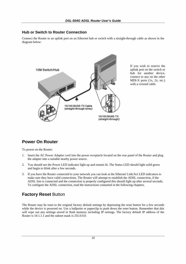
Hub or Switch to Router Connection Connect the Router to an uplink port on an Ethernet hub or switch with a straight-through cable as shown in the diagram below:
Power On Router To power on the Router:
1. Insert the AC Power Adapter cord into the power receptacle located on the rear panel of the Router and plug the adapter into a suitable nearby power source.
2. You should see the Power LED indicator light up and remain lit. The Status LED should light solid green and begin to blink after a few seconds.
3. If you have the Router connected to your network you can look at the Ethernet Link/Act LED indicators to make sure they have valid connections. The Router will attempt to establish the ADSL connection, if the ADSL line is connected and the connection is properly configured this should light up after several seconds. To configure the ADSL connection, read the instructions contained in the following chapters.
Factory Reset Button
The Router may be reset to the original factory default settings by depressing the reset button for a few seconds while the device is powered on. Use a ballpoint or paperclip to push down the reset button. Remember that this will wipe out any settings stored in flash memory including IP settings. The factory default IP address of the Router is 10.1.1.1 and the subnet mask is 255.0.0.0.
If you wish to reserve theuplink port on the switch orhub for another device,connect to any on the otherMDI-X ports (1x, 2x, etc.)with a crossed cable.

DSL-504G ADSL Router User’s Guide
11
3 Basic Router Configuration The first time you setup the Router it is recommended that you configure the WAN connection using a single computer making sure that both the computer and the Router are not connected to the LAN. Once the WAN connection is functioning properly you may continue change settings to suit your network. This chapter is only concerned with settings up the WAN connection. The following chapter, Web-based Management Guide, describes the various menus used to configure and monitor the Router including how to change IP settings and DHCP server setup.
Wan Configuration Summary 1. Connect to the Router To configure the WAN connection used by the Router it is first necessary to
communicate with the Router through its management interface, which is HTML-based and can be accessed using a web browser. To access the management software your computer must be able to “see” the Router. Your computer can see the Router if it is in the same “neighborhood” or subnet as the Router. This is accomplished by making sure your computer has IP settings that place it in the same subnet as the Router. The easiest way to make sure your computer has the correct IP settings is to configure it to use the DHCP server in the Router. The next section describes how to change the IP configuration for a computer running a Windows operating system to be a DHCP client.
2. Configure the WAN Connection Once your are able to access the configuration software you can proceed to change the settings required to establish the ADSL connection and connect to the service provider’s network. There are different methods used to establish the connection to the service provider’s network and ultimately to the Internet. You should know what Encapsulation and connection type you are required to use for your ADSL service. It is also possible that you must change the PVC settings used for the ADSL connection. Your service provider should provide all the information you need to configure the WAN connection.
Configuring IP Settings on Your Computer In order to configure your system to receive IP settings from the Router it must first have the TCP/IP protocol installed. If you have an Ethernet port on your computer, it probably already has TCP/IP protocol installed. If you are using Windows XP the TCP/IP is enabled by default for standard installations. Below is an illustrated example of how to configure a Windows XP system to automatically obtain IP settings from the Router. Following this example is a step-by-step description of the procedures used on the other Windows operating systems to first check if the TCP/IP protocol has been installed, if it is not instruction are provided for installing it. Once the protocol has been installed you can configure the system to receive IP settings from the Router.
For computers running non-Windows operating systems, follow the instructions for your OS that configure the system to receive an IP address from the Router, that is, configure the system to be a DHCP client.
Note
If you are using this Router to provide Internet access for more than one computer, you can use these instructions later to change the IP settings for the other computers. However you cannot use the same IP address since every computer must have its own IP address that is unique on the local network.
DSL-504G ADSL Router User’s Guide
12
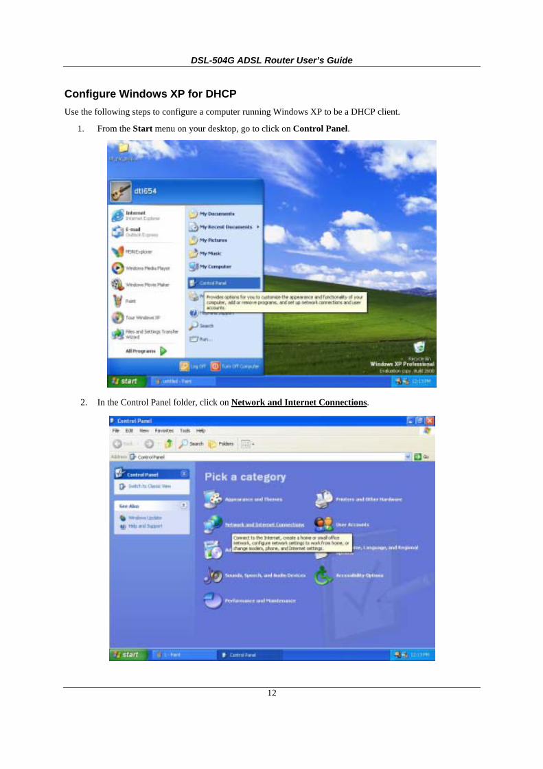
Configure Windows XP for DHCP Use the following steps to configure a computer running Windows XP to be a DHCP client.
1. From the Start menu on your desktop, go to click on Control Panel.
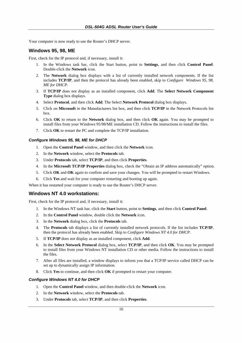
2. In the Control Panel folder, click on Network and Internet Connections.

DSL-504G ADSL Router User’s Guide
13
3. In the Network and Internet Connections folder, click on Network Connections.
4. In the Network Connections folder, highlight the Local Area Connection icon by clicking on it once. A new option is revealed under Network Tabs in the left side panel.

DSL-504G ADSL Router User’s Guide
14
5. Click on Change settings of the connection under Network Tabs.
6. In the General Tab of the Local Area Connection Properties menu, highlight Internet Protocol
(TCP/IP) under “This connection uses the following items:” by clicking on it once. Click on the Properties button.

DSL-504G ADSL Router User’s Guide
15
7. Select “Obtain an IP address automatically” by clicking once in the circle. Click the OK button.
Your computer is now ready to use the Router’s DHCP server.
Windows 2000 First, check for the IP protocol and, if necessary, install it:
1. In the Windows task bar, click the Start button, point to Settings, and then click Control Panel.
2. Double-click the Network and Dial-up Connections icon.
3. In the Network and Dial-up Connections window, right-click the Local Area Connection icon, and then select Properties.
4. The Local Area Connection Properties dialog box displays with a list of currently installed network components. If the list includes Internet Protocol (TCP/IP), then the protocol has already been enabled, skip ahead to Configure Windows 2000 for DHCP.
5. If Internet Protocol (TCP/IP) does not display as an installed component, click Install.
6. In the Select Network Component Type dialog box, select Protocol, and then click Add.
7. Select Internet Protocol (TCP/IP) in the Network Protocols list, and then click OK.
8. You may be prompted to install files from your Windows 2000 installation CD or other media. Follow the instructions to install the files.
9. If prompted, click OK to restart your computer with the new settings.
Configure Windows 2000 for DHCP 1. In the Control Panel, double-click the Network and Dial-up Connections icon. 2. In the Network and Dial-up Connections window, right-click on the Local Area Connection icon,
and then select Properties. 3. In the Local Area Connection Properties window, select Internet Protocol (TCP/IP), and then click
on the Properties button. 4. Select “Obtain an IP address automatically” by clicking once in the circle. 5. Click OK and OK again to confirm and save your changes, and then close the Network and Dial-up
Connections window.
DSL-504G ADSL Router User’s Guide
16
Your computer is now ready to use the Router’s DHCP server.
Windows 95, 98, ME First, check for the IP protocol and, if necessary, install it:
1. In the Windows task bar, click the Start button, point to Settings, and then click Control Panel. Double-click the Network icon.
2. The Network dialog box displays with a list of currently installed network components. If the list includes TCP/IP, and then the protocol has already been enabled, skip to Configure Windows 95, 98, ME for DHCP.
3. If TCP/IP does not display as an installed component, click Add. The Select Network Component Type dialog box displays.
4. Select Protocol, and then click Add. The Select Network Protocol dialog box displays. 5. Click on Microsoft in the Manufacturers list box, and then click TCP/IP in the Network Protocols list
box. 6. Click OK to return to the Network dialog box, and then click OK again. You may be prompted to
install files from your Windows 95/98/ME installation CD. Follow the instructions to install the files. 7. Click OK to restart the PC and complete the TCP/IP installation.
Configure Windows 95, 98, ME for DHCP 1. Open the Control Panel window, and then click the Network icon. 2. In the Network window, select the Protocols tab. 3. Under Protocols tab, select TCP/IP, and then click Properties. 4. In the Microsoft TCP/IP Properties dialog box, check the “Obtain an IP address automatically” option. 5. Click OK and OK again to confirm and save your changes. You will be prompted to restart Windows. 6. Click Yes and wait for your computer restarting and booting up again.
When it has restarted your computer is ready to use the Router’s DHCP server.
Windows NT 4.0 workstations: First, check for the IP protocol and, if necessary, install it:
1. In the Windows NT task bar, click the Start button, point to Settings, and then click Control Panel. 2. In the Control Panel window, double click the Network icon. 3. In the Network dialog box, click the Protocols tab. 4. The Protocols tab displays a list of currently installed network protocols. If the list includes TCP/IP,
then the protocol has already been enabled. Skip to Configure Windows NT 4.0 for DHCP. 5. If TCP/IP does not display as an installed component, click Add. 6. In the Select Network Protocol dialog box, select TCP/IP, and then click OK. You may be prompted
to install files from your Windows NT installation CD or other media. Follow the instructions to install the files.
7. After all files are installed, a window displays to inform you that a TCP/IP service called DHCP can be set up to dynamically assign IP information.
8. Click Yes to continue, and then click OK if prompted to restart your computer.
Configure Windows NT 4.0 for DHCP 1. Open the Control Panel window, and then double-click the Network icon. 2. In the Network window, select the Protocols tab. 3. Under Protocols tab, select TCP/IP, and then click Properties.

DSL-504G ADSL Router User’s Guide
17
4. In the Microsoft TCP/IP Properties dialog box, check the “Obtain an IP address automatically” option. 5. Click OK and OK again to confirm and save your changes. You will be prompted to restart Windows. 6. Click Yes and wait for your computer restarting and booting up again.
Your computer is now ready to use the Router’s DHCP server.

DSL-504G ADSL Router User’s Guide
18
Access the Web Manager Once the computer has IP settings that allow it to access the web-based configuration software, you can change the settings to enable the Router to connect to the Internet.
If the browser software on the computer you are using is configured to use a proxy server for Internet access, it is necessary to first disable the proxy connection.
Check for Proxy service in Windows Internet Explorer:
In Windows Internet Explorer, you can check if a proxy server is enabled using the following procedure:
1. From the Start menu, go to Control Panel, or Settings then Control Panel.
2. In the Control Panel window, double-click on the Internet Options icon.
3. Click the Connections tab and click on the LAN Settings… button near the bottom.
4. Verify that the “Use a proxy server” option is NOT checked. If it is checked, click in the checkbox to deselect the option and click OK and OK again. Close the Control Panel window.
To use the web-based management software, launch your web browser software and use the LAN IP address of the Router to access the management software. The default LAN IP address of the Router is used in the Address bar of your web browser window. Type in http:// followed by the default IP address, 10.1.1.1 in the address bar of the browser. The URL in the address bar should read: http://10.1.1.1
A new window appears prompting you for a user name and password needed to gain access the web configuration manager.
Use the default system user name: admin and password: admin for first time set up. You can change the password once you have established the ADSL connection. The user name and password allows any computer on the same subnet as the Router to access the web configuration manger. This password can also be used to Telnet to the device through the Ethernet or the Internet interfaces. To change this password, see the next chapter.
When you successfully login the Home directory tab will display the Setup Wizard menu. You can launch the Setup Wizard from this page or use the menu buttons located in the left panel of the web page to view other menus used for basic configuration. You may use the Setup Wizard if your Internet connection is a PPPoE connection. If you are using a PPPoE and connection and want to use the Setup Wizard, follow the instructions below. If your Internet connection is a PPPoA, Bridge, Static IP, or Dynamic IP type connection, you should follow the instructions below in the section Configure WAN Connection.

DSL-504G ADSL Router User’s Guide
19
Web Manager – First Time Log On
Using the Web Manager All configuration and management of the Router is done using the web-based management interface pictured in the above example. The various menus accessed by clicking on one of the directory tabs, Home, Advanced, Tools, Status and Help. Each tab displays menu buttons located in the left hand panel of the web interface. The table below lists the menus for each directory in the web manager.
Directory Configuration and Read-only Menus
Home Click the Home tab to access the Setup Wizard, WAN Configuration, LAN IP Configuration, DHCP for the LAN Setup and DNS IP Configuration menus.
Advanced Click the Advanced tab to access the Virtual Server, IP Filters, IP Routing, DMZ, Firewall, RIP, PPP, ADSL and ATM VCC menus.
Tools Click the Tools tab to access the Administrator Settings (used to set the system user name and password), System Time Configuration, System Settings (load and save configuration files), Firmware Upgrade, Miscellaneous Configuration (Save & Reboot, Ping test, enable IGMP) and Diagnostic Test menus.
Status Click the Status tab to view the Device Information, Event Log, Traffic Statistics and ADSL Status information windows.
Help The Help menu presents links to pages that explain various functions and services provided by the Router.
Click here to run the Setup Wizard
to setup the Internet
connection
Click on a tab to view the menus available in that
directory
Click on a menu button to use or view the menu
DSL-504G ADSL Router User’s Guide
20
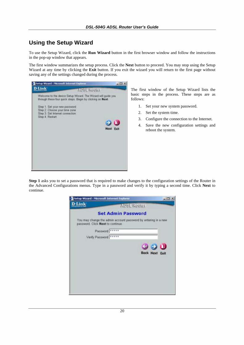
Using the Setup Wizard To use the Setup Wizard, click the Run Wizard button in the first browser window and follow the instructions in the pop-up window that appears.
The first window summarizes the setup process. Click the Next button to proceed. You may stop using the Setup Wizard at any time by clicking the Exit button. If you exit the wizard you will return to the first page without saving any of the settings changed during the process.
The first window of the Setup Wizard lists the basic steps in the process. These steps are as follows:
1. Set your new system password. 2. Set the system time. 3. Configure the connection to the Internet. 4. Save the new configuration settings and
reboot the system.
Step 1 asks you to set a password that is required to make changes to the configuration settings of the Router in the Advanced Configurations menus. Type in a password and verify it by typing a second time. Click Next to continue.

DSL-504G ADSL Router User’s Guide
21
Set the system time of the Router in Step 2. Choose the time zone you are in from the pull-down menu and click Next. If you wish to return to the previous menu during the setup process, click the Back button.
In Step 3 you Select the Internet Connection Type for the WAN interface. Your ISP has given this information to you. If you do not know what type of connection to use, exit the Setup Wizard and contact your ISP for the information. The Setup wizard menu that appears when you click the Next button depends on what connection type you select. The connection types available in the Setup Wizard menu are Dynamic IP Address, Static IP Address, PPPoE/PPPoA and Bridge Mode. Follow the instructions below for the type of connection you are using.

DSL-504G ADSL Router User’s Guide
22
PPPoE/PPPoA Connections
If you selected the PPPoE/PPPoA connection type in the previous menu, you will see the Setup Wizard menu pictured here. Type in the Username and Password used to identify and verify your account to the ISP. If you have been instructed to change the VPI number and VCI number, type in the new values. Select the Connection Type used for encapsulation specific to your service. Click Next when you are ready to proceed to the Setup Completed menu.
Note
Do not confuse the user name and password used to access the web-based manager with the ADSL account user name and password needed for PPPoE connections to access the ISP’s network.
Dynamic IP Address Connections
If you selected the Dynamic IP Addressconnection type, select the Connection Typeused for encapsulation. If you have beeninstructed to change the VPI number and VCInumber, type in the new values. Click Nextwhen you are ready to proceed to the SetupCompleted menu.

DSL-504G ADSL Router User’s Guide
23
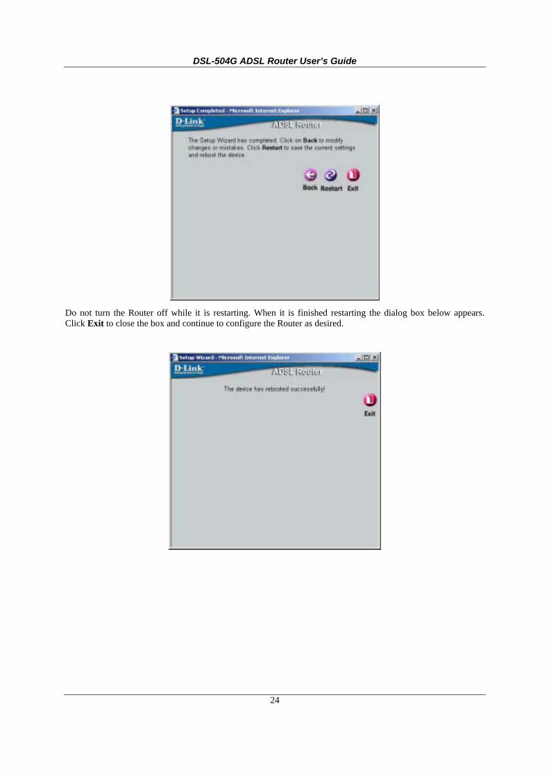
Finally you can confirm that the setup process is completed. If you are satisfied that you have entered all the necessary information correctly, click the Restart button to save the new configuration settings and restart the Router. If you need to change settings from a previous menu, click the Back button.
Static IP Address Connections
If you selected the Static IP Addressconnection type, change the WAN IPAddress, Subnet Mask, ISP GatewayAddress and (if available) SecondaryDNS Server IP address as instructed byyour ISP. Select the Connection Typeused for encapsulation. If you havebeen instructed to change the VPInumber and VCI number, type in thenew values. Click Next when you areready to proceed to the SetupCompleted menu.
Bridge Connections
If you selected the Bridge connectiontype, select the Connection Type used forencapsulation. If you have been instructedto change the VPI number and VCInumber, type in the new values. ClickNext when you are ready to proceed to theSetup Completed menu.
DSL-504G ADSL Router User’s Guide
24
Do not turn the Router off while it is restarting. When it is finished restarting the dialog box below appears. Click Exit to close the box and continue to configure the Router as desired.

DSL-504G ADSL Router User’s Guide
25
Configure WAN Connection To configure the Router’s basic configuration settings without running the Setup Wizard, you can access the menus used to configure WAN, LAN, DHCP and DNS settings directly from the Home directory. To access the WAN Settings menu, click on the WAN link button on the left side of the first window that appears when you successfully access the web manager.
The WAN Settings menu is also used to configure the Router for multiple virtual connections. The next chapter contains information on how to configure the Router for Multiple PVCs.
WAN Settings Menu – PPPoE / PPPoA
Select the connection type used for your account. The menu will display settings that are appropriate for the connection type you select. Follow the instruction below according to the type of connection you select in the WAN Settings menu.

DSL-504G ADSL Router User’s Guide
26
PPPoE and PPPoA Connection for WAN Most ADSL accounts will use either PPPoE or PPPoA type connections. Follow the instructions below to configure the Router to use a PPPoE or PPPoA for the Internet connection. Make sure you have all the necessary information before you configure the WAN connection. See the Record Your Account Information table in the first section of this manual for a summary of the information you will need.
1. Click to select the PPPoE/PPPoA radio button in the WAN Settings options list. This is selected by default if you are configuring the Router for the first time. If it is not selected, click the PPPoE/PPPoA radio button located under the WAN Settings heading.
2. Under the PPPoE/PPPoA heading, type the User Name and Password used for your ADSL account. A typical User Name will be in the form [email protected], the Password may be assigned to you by your ISP or you may have selected it when you set up the account with your ISP.
3. Choose the Connection Type from the pull-down menu located under the User Name and Password entry fields. This defines both the connection protocol and encapsulation method used for your ADSL service. The available options are PPPoA VC-MUX, PPPoA LLC, PPPoE VC-MUX and PPPoE LLC. Most users in Australia will use PPPoA VC-Mux, or PPPoE LLC. Most users in New Zealand will use PPPoA VC-Mux. If have not been provided specific information for the Connection Type setting, leave the default setting.
4. Leave the MRU value at the default setting (default = 1492) unless you have been instructed to change this.
5. Select the Authentication method as instructed by your ISP. Choose PAP or CHAP from the pull-down menu.
6. The Obtain DNS Automatically is Enabled by default. When this is enabled, the Router will request DNS settings from your ISP’s DNS server. If your ISP has provided a specific IP address to use for DNS, you should select Disabled and manually configure DNS settings in the DNS menu (see Configure DNS below). You will not be able to access Internet web sites until the DNS settings are properly configured. Be sure to configure this before you save the new settings and restart the Router.
7. If you are instructed to use enable Default Route, this setting specifies that the Router be used to define the default route to the Internet for your LAN. Whenever a computer on the LAN attempts to access the Internet, the Router becomes the Internet gateway to the computer.
8. The ATM VC Settings at the top of the menu should not be changed unless you have been instructed to change them. However, if you are instructed to change the VPI or VCI values, type in the values assigned for your account. Most users in Australia will use a VPI of 8, and a VCI of 35. Most users in New Zealand will use a VPI of 0, and a VCI of 100. Leave the PVC and Virtual Circuit settings at their default (Pcv0 and Enabled) values for now. These can be used later if you are configuring multiple virtual circuits for your ADSL service.
9. When you are satisfied that all the WAN settings are configured correctly, click on the Apply button.
10. The new settings must be saved and the Router must be restarted for the settings to go into effect. To Save & Reboot the Router, click on the Tools directory tab and then click the Misc (Miscellaneous) menu button. In the Miscellaneous menu, click he Save & Reboot button. The Router will save the new settings and restart. Upon restarting the Router will automatically establish a connection to the Internet.

DSL-504G ADSL Router User’s Guide
27
Bridged Connection for WAN For Bridged connections it will be necessary for most users to install additional software on any computer that will the Router for Internet access. The additional software is used for the purpose of identifying and verifying your account, and then granting Internet access to the computer requesting the connection. The connection software requires the user to enter the User Name and Password for the ISP account. This information is stored on the computer, not in the Router.
Follow the instructions below to configure a Bridged connection for the WAN interface.
WAN Settings Menu – Bridge Mode
1. Click to select the Bridge Mode radio button in the WAN Settings options list. The menu will change to offer a different set of configuration options.
2. Under the ATM VC Setting heading, do not change the PVC (Pvc0) index for the initial connection.
3. Also under the ATM VC Setting, you see two numbers, the VCI and VPI values. Do not change the VPI or VCI value unless you have been told to do so. These numbers are used to define a unique path for your connection. Most users in Australia will use a VPI of 8, and a VCI of 35. Most users in New Zealand will use a VPI of 0, and a VCI of 100. If you have been given specific settings for this to configure, type in the correct values assigned by your ISP.
4. Change the Virtual Circuit setting to Enabled in the pull-down menu.
5. When you are satisfied that all the WAN settings are configured correctly, click on the Apply button.
6. The new settings must be saved and the Router must be restarted for the settings to go into effect. To Save & Reboot the Router, click on the Tools directory tab and then click the Misc (Miscellaneous) menu button. In the Miscellaneous menu, click he Save & Reboot button. The Router will save the new settings and restart. Upon restarting the Router will automatically establish the WAN connection.
Note
Some accounts use PPP connection software for their Internet service connection. If you have been given a CD with PPP connection software, install this now as instructed by your service provider. After the Router has rebooted it will negotiate the ADSL connection. Use the connection software to log on to the ISP network and access the Internet.

DSL-504G ADSL Router User’s Guide
28
Dynamic IP Address for WAN Connection When the Router is configured to use Dynamic IP Address assignment for the WAN connection, a server on the ISP’s network assigns the global IP address settings used for the WAN connection. This is method is simply Dynamic Host Control Protocol (DHCP) for the WAN. The Router is configured to be a DHCP client and obtain its IP settings automatically for the DHCP server owned by the ISP. Follow the instruction below to configure the Router to use Dynamic IP Address assignment for the WAN connection.
WAN Settings - Dynamic IP Address
1. Click to select the Dynamic IP Address radio button listed in the WAN Settings options list. The menu will change to offer a different set of configuration options.
2. Select the Connection Type from the pull-down menu under the Dynamic IP heading. Your ISP should provide this information to you. The available option are 1483 Routed VC-Mux, 1483 Routerd LLC, IpoA VC-Mux, IpoA LLC and IpoA (1577). If have not been provided specific information for the Connection Type setting, leave the default setting.
3. If you are instructed to use enable Default Route, this setting specifies that the Router be used to define the default route to the Internet for your LAN. Whenever a computer on the LAN attempts to access the Internet, the Router becomes the Internet gateway to the computer.
4. Under the ATM VC Setting heading, do not change the PVC (Pvc0) index for the initial connection. 5. Also under the ATM VC Setting, you see two numbers, the VCI and VPI values. Do not change the
VPI or VCI value unless you have been told to do so. These numbers are used to define a unique path for your connection. Most users in Australia will use a VPI of 8, and a VCI of 35. Most users in New Zealand will use a VPI of 0, and a VCI of 100. If you have been given specific settings for this to configure, type in the correct values assigned by your ISP.
6. Change the Virtual Circuit setting to Enabled in the pull-down menu. 7. When you are satisfied that all the WAN settings are configured correctly, click on the Apply button. 8. The new settings must be saved and the Router must be restarted for the settings to go into effect. To
Save & Reboot the Router, click on the Tools directory tab and then click the Misc (Miscellaneous) menu button. In the Miscellaneous menu, click he Save & Reboot button. The Router will save the new settings and restart. Upon restarting the Router will automatically establish the WAN connection.

DSL-504G ADSL Router User’s Guide
29
Static IP Address for WAN Connection When the Router is configured to use Static IP Address assignment for the WAN connection, you must manually assign a global IP Address, Subnet Mask and Gateway IP Address used for the WAN connection. Most users will also to configure DNS server IP settings in the DNS Settings configuration menu (see below). Follow the instruction below to configure the Router to use Static IP Address assignment for the WAN connection.
WAN Settings - Static IP
1. Clk to select the Static IP Address radio button listed in the WAN Settings options list. The menu will change to offer a different set of configuration options.
2. Select the Connection Type from the pull-down menu under the Static IP heading. Your ISP should provide this information to you. The available option are 1483 Routed VC-Mux, 1483 Routerd LLC, IpoA VC-Mux, IpoA LLC and IpoA (1577). If have not been provided specific information for the Connection Type setting, leave the default setting.
3. Change the IP Address, Subnet Mask and ISP Gateway Address as instructed by your ISP. Your ISP should have provided these IP settings to you.
4. If you are instructed to use enable Default Route, this setting specifies that the Router be used to define the default route to the Internet for your LAN. Whenever a computer on the LAN attempts to access the Internet, the Router becomes the Internet gateway to the computer.
5. Under the ATM VC Setting heading, do not change the PVC (Pvc0) index for the initial connection. 6. Also under the ATM VC Setting, you see two numbers, the VCI and VPI values. Do not change the
VPI or VCI value unless you have been told to do so. These numbers are used to define a unique path for your connection. Most users in Australia will use a VPI of 8, and a VCI of 35. Most users in New Zealand will use a VPI of 0, and a VCI of 100. If you have been given specific settings for this to configure, type in the correct values assigned by your ISP.
7. Change the Virtual Circuit setting to Enabled in the pull-down menu. 8. When you are satisfied that all the WAN settings are configured correctly, click on the Apply button. 9. The new settings must be saved and the Router must be restarted for the settings to go into effect. To
Save & Reboot the Router, click on the Tools directory tab and then click the Misc (Miscellaneous) menu button. In the Miscellaneous menu, click he Save & Reboot button. The Router will save the new settings and restart. Upon restarting the Router will automatically establish the WAN connection.

DSL-504G ADSL Router User’s Guide
30
LAN IP Settings You can configure the LAN IP address to suit your preference. Many users will find it convenient to use the default settings together with DHCP service to manage the IP settings for their private network. The IP address of the Router is the base address used for DHCP. In order to use the Router for DHCP on your LAN, the IP address pool used for DHCP must be compatible with the IP address of the Router. The IP addresses available in the DHCP IP address pool will change automatically if you change the IP address of the Router. See the next section for information on DHCP setup.
To access the LAN Settings menu, click the LAN button in the Home directory.
Configure LAN IP settings
To change the LAN IP Address or LAN Network Mask, type in the desired values and click the Apply button. The new IP settings must be saved and the Router must be restarted for the settings to go into effect. To Save & Reboot the Router, click on the Tools directory tab and then click the Misc (Miscellaneous) menu button. In the Miscellaneous menu, click the Save & Reboot button. The Router will save the new IP settings and restart. Your web browser should automatically be redirected to the new IP address. The new IP settings will be applied upon restarting.
DSL-504G ADSL Router User’s Guide
31
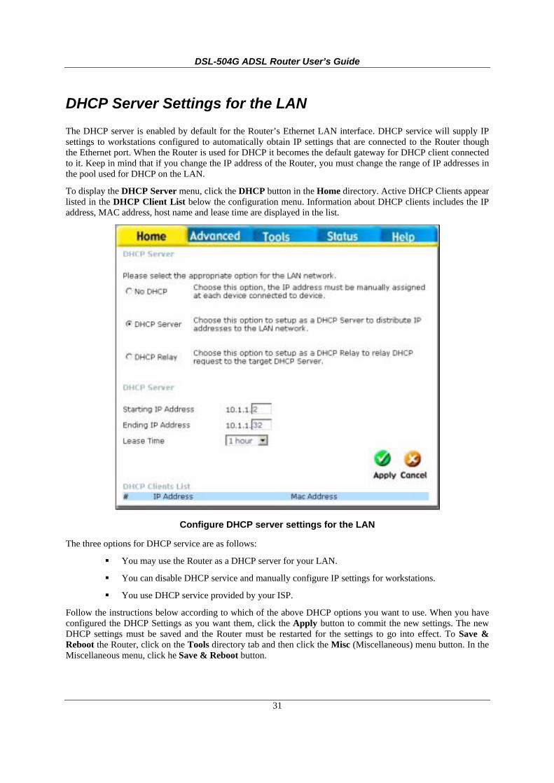
DHCP Server Settings for the LAN The DHCP server is enabled by default for the Router’s Ethernet LAN interface. DHCP service will supply IP settings to workstations configured to automatically obtain IP settings that are connected to the Router though the Ethernet port. When the Router is used for DHCP it becomes the default gateway for DHCP client connected to it. Keep in mind that if you change the IP address of the Router, you must change the range of IP addresses in the pool used for DHCP on the LAN.
To display the DHCP Server menu, click the DHCP button in the Home directory. Active DHCP Clients appear listed in the DHCP Client List below the configuration menu. Information about DHCP clients includes the IP address, MAC address, host name and lease time are displayed in the list.
Configure DHCP server settings for the LAN
The three options for DHCP service are as follows:
You may use the Router as a DHCP server for your LAN.
You can disable DHCP service and manually configure IP settings for workstations.
You use DHCP service provided by your ISP.
Follow the instructions below according to which of the above DHCP options you want to use. When you have configured the DHCP Settings as you want them, click the Apply button to commit the new settings. The new DHCP settings must be saved and the Router must be restarted for the settings to go into effect. To Save & Reboot the Router, click on the Tools directory tab and then click the Misc (Miscellaneous) menu button. In the Miscellaneous menu, click he Save & Reboot button.

DSL-504G ADSL Router User’s Guide
32
Use the Router for DHCP To use the built-in DHCP server, click to select the DHCP Server option if it is not already selected. The IP Address Pool settings can be adjusted so that up to 253IP addresses are available for use. The Starting IP Address is the lowest available IP address (default = 10.1.1.2). If you change the IP address of the Router this will change automatically to be 1 more that the IP address of the Router. The Ending IP Address is the highest IP address number in the pool. Select the Lease Time from the pull-down menu. This is the amount of time that a workstation is allowed to reserve an IP address in the pool if the workstation is disconnected from the network or powered off. Lease time options vary from 1 hour to 1 week. DHCP client workstations on your LAN must be properly configured to use DHCP service. Be sure to save the new settings.
Use the ISP’s DHCP Server Some ISP’s can provide DHCP service for individual workstations on your private LAN. To use the service you will need the IP address of the DHCP server on your ISP’s network. When this option is selected, the Router automatically forwards DHCP requests from clients on your LAN to the outside DHCP server, and then forwards the DHCP reply from the server to the client. DHCP Relay can be used for any WAN setting connection type.
DHCP Server Relay
To setup DHCP relay, click to select the DHCP Relay option. The menu will display the DHCP Relay IP entry field. This is used to enter the IP address of the outside DHCP server to which requests are forwarded. Enter the IP address of the ISP’s DHCP server and click the Apply button. DHCP client workstations on your LAN must be properly configured to use DHCP from the ISP’s server. Be sure to save the new settings.
Disable the DHCP Server To disable DHCP, click to select the No DHCP option and click on the Apply button. Be sure to save the new settings.
DSL-504G ADSL Router User’s Guide
33
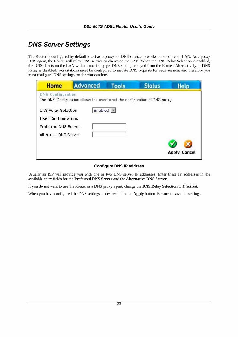
DNS Server Settings The Router is configured by default to act as a proxy for DNS service to workstations on your LAN. As a proxy DNS agent, the Router will relay DNS service to clients on the LAN. When the DNS Relay Selection is enabled, the DNS clients on the LAN will automatically get DNS settings relayed from the Router. Alternatively, if DNS Relay is disabled, workstations must be configured to initiate DNS requests for each session, and therefore you must configure DNS settings for the workstations.
Configure DNS IP address
Usually an ISP will provide you with one or two DNS server IP addresses. Enter these IP addresses in the available entry fields for the Preferred DNS Server and the Alternative DNS Server.
If you do not want to use the Router as a DNS proxy agent, change the DNS Relay Selection to Disabled.
When you have configured the DNS settings as desired, click the Apply button. Be sure to save the settings.

DSL-504G ADSL Router User’s Guide
34
Save New Settings Any changes you have made to the must be saved to the Router’s memory and the device must be restarted for the settigns to take effect. To save settings you need to access the Miscellaneous Configuration menu. Click on the Tools directory tab then click the Misc menu button to view the menu pictured below.
Save Settings and Restart the Router
To save the new settings, click the Save and Reboot button. It will take about two minutes for the whole process to be completed. Do not turn off the power while the Router is saving and restarting.

DSL-504G ADSL Router User’s Guide
35
4 Advanced Configuration/Network Management This chapter introduces and describes the management features that have not been presented in the previous chapter. These include the more advanced features used for network management and security as well as administrative tools to manage the Router, view statistics and other information used to examine performance and for troubleshooting.
Use your mouse to click the directory tabs and menu buttons in order to display the various configuration and read-only menus discussed below. The table below summarizes again the directories and menus available in the management web interface. In this chapter you will find descriptions for the menus located in the Advanced, Tools and Status directories. If you are setting up the Router for multiple virtual connections (multiple PVCs), please skip ahead to the section Multiple Virtual Connections.
Figure 4- 1. Advanced configuration menus
Directory Configuration and Read-only Menus
Home Click the Home tab to access the Setup Wizard, WAN Configuration, LAN IP Configuration, DHCP for the LAN Setup and DNS IP Configuration menus. These menus are discussed in the previous Chapter on Basic Router Configuration.
Advanced Click the Advanced tab to access the NAT, Virtual Server, IP Filters, IP Routing, DMZ, Firewall, RIP, PPP, ADSL and ATM VCC menus.
Tools Click the Tools tab to access the Administrator Settings (used to set the system user name and password), System Time Configuration, System Settings (load and save configuration files), Firmware Upgrade, Miscellaneous Configuration (Save & Reboot, Ping test, enable IGMP) and Diagnostic Test menus.
Status Click the Status tab to view the Device Information, Event Log, Traffic Statistics and ADSL Status information windows.
Help The Help menu presents links to pages that explain various functions and services provided by the Router.
DSL-504G ADSL Router User’s Guide
36
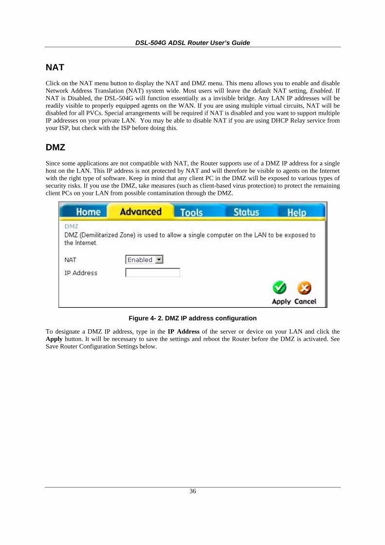
NAT Click on the NAT menu button to display the NAT and DMZ menu. This menu allows you to enable and disable Network Address Translation (NAT) system wide. Most users will leave the default NAT setting, Enabled. If NAT is Disabled, the DSL-504G will function essentially as a invisible bridge. Any LAN IP addresses will be readily visible to properly equipped agents on the WAN. If you are using multiple virtual circuits, NAT will be disabled for all PVCs. Special arrangements will be required if NAT is disabled and you want to support multiple IP addresses on your private LAN. You may be able to disable NAT if you are using DHCP Relay service from your ISP, but check with the ISP before doing this.
DMZ Since some applications are not compatible with NAT, the Router supports use of a DMZ IP address for a single host on the LAN. This IP address is not protected by NAT and will therefore be visible to agents on the Internet with the right type of software. Keep in mind that any client PC in the DMZ will be exposed to various types of security risks. If you use the DMZ, take measures (such as client-based virus protection) to protect the remaining client PCs on your LAN from possible contamination through the DMZ.
Figure 4- 2. DMZ IP address configuration
To designate a DMZ IP address, type in the IP Address of the server or device on your LAN and click the Apply button. It will be necessary to save the settings and reboot the Router before the DMZ is activated. See Save Router Configuration Settings below.

DSL-504G ADSL Router User’s Guide
37
Virtual Server A Virtual Server can allow remote users to access services on your LAN such as FTP for file transfers or SMTP and POP3 for e-mail. The DSL-504G will accept remote requests for these services at your Global IP Address, using the specified TCP or UDP protocol and port number, and then redirect these requests to the server on your LAN with the Private IP address you specify. Remember that the Private IP Address must be within the range specified for your LAN.
The Virtual Server feature employs UDP/TCP port redirection to direct traffic through the WAN port to specified servers on your private network. Port redirection can also be used to direct potentially hazardous packets to a proxy server outside your firewall. For example, you can configure the Router to direct HTTP packets to a designated HTTP server in the DMZ. You can define a set of instructions for a specific incoming port or for a range of incoming ports. Each instruction set or rule is indexed and can be modified or deleted later as needed.
Virtual server configuration sets can be used together with complimentary features such as Firewall Rules, DMZ devices and IP Filters to improve efficiency and security. Consider how these other functions will effect the virtual server sets you have configured and enabled.
The table below describes the configuration settings presented in the Virtual Server menu.
NAT Configuration The Virtual Server menu also allows you to enable and disable Network Address Translation (NAT) system wide. See the previous discussion of NAT if you intend to disable it.
Figure 4- 3. Virtual Server Menu and List
To modify virtual server settings for any previously created virtual server set listed, click on the note pad icon in the right hand column of the Virtual Servers List for the set you want to configure. The set will appear highlighted in the list and the parameters that have been configured appear in the settings fields above the list. Adjust the settings as desired and click the Apply button to put them into effect.

DSL-504G ADSL Router User’s Guide
38
To configure a virtual server set, define the following settings in the Virtual Server configuration menu located in the top half of the browser window.
NAT Network Address Translation (NAT) can be enabled or disabled system wide. Under certain circumstances it may be desirable to disable NAT, however this will render other router functions (such as DHCP) useless. Most users will leave NAT enabled.
Private IP
This is the IP address of the server on your LAN that will provide the service to remote users. The Private IP address is used to direct the service to a specific computer on your private network such as an FTP, Email or public web server. Type in the IP address of the server used for the service being configured here.
Protocol Type
You can select the transport protocol (TCP or UDP) that the application on the virtual server will use for its connections. Select to redirect TCP, UDP or Both (All) types of packets from the pull-down menu. The choice of this protocol is dependent on the application that is providing the service. If you do not know which protocol to choose, check your application’s documentation.
Private Port
This is the TCP/UDP port on LAN (Private) interface. Keep in mind that if you use a non-standard port number for an application with a reserved UDP/TCP port, some additional configuration may be required for the servers or workstations using the application on the LAN side. Port redirection must be used with a specified server or computer on the LAN (identified by the Private IP address).
Public Port
The Public Port is the TCP/UDP port on the WAN interface. Select one of the following options from the pull-down menu to define a Single Port, Range of Ports, Any Port or Safe Ports (ports above 1024). If you are redirecting a single standard TCP/UDP port from the WAN to the LAN, select the Single Port option and use the standard port number here (such as port 23 for Telnet or port 25 for SMTP). If choose the Any Port option, all TCP/UDP traffic will be directed as specified.
Click the Apply button to put the new virtual server configuration set or modification into effect. Any server sets configured in the menu will appear in the Virtual Server List with the new settings. The Router must save the new settings and reboot before the new virtual server configurations are applied.
To remove any configuration set from the Virtual Server List, click on the trashcan icon for set you want to delete.
Note
Some applications require multiple TCP or UDP ports to function properly. Applications such as Internet gaming, video conferencing, and Internet telephony are some examples of applications that often require multiple connections. These applications often conflict with NAT, and therefore require special handling. See the discussion of DMZ configuration below.

DSL-504G ADSL Router User’s Guide
39
Filters Filter rules in the Router are put in place to allow or block specified traffic. The Filter Rules however can be used in a single direction to examine and then Allow or Deny traffic for Inbound (WAN to LAN) or Outbound (LAN to WAN) routed data. The rules based on IP address and TCP/UDP port.
Configure the filter rules as desired and click the Apply button to create the rule. The newly created rule appears listed in the Outbound Filter List at the bottom of the menu. The table below describes the various parameters that are configured for the filter rules.
Figure 4- 4. Filters Configuration Menu
To modify any previously created filter rule, click on the note pad icon in the right hand column of the Inbound Filter or Outbound Filter List for the set you want to configure. The set will appear highlighted in the list and the parameters that have been configured appear in the settings fields above the list. Adjust the settings as desired and click the Apply button to put the new settings into effect.

DSL-504G ADSL Router User’s Guide
40
First determine the direction of the traffic you want the rule to filter. To filter WAN to LAN traffic, select the Inbound Filter option; notice that the Filter List at the bottom of the menu displays the Inbound Filter List. Any new Inbound Filter rules created will appear in the list. Likewise, should you choose to create an Outbound Filter rule, the Outbound Filter List of rules will appear at the bottom of the menu.
Source IP
For an Outbound Filter, this is the IP address or IP addresses on your LAN for which you are creating the filter rule. For an Inbound Filter, this is the IP address or IP addresses for which you are creating the filter rule. You can opt to indicate a Single IP, an IP Range or Any IP from the pull-down menu. Choosing Any IP will apply the rule to all WAN or all LAN IP addresses depending on which type of rule (Inbound or Outbound) is being configured.
Destination IP Where the Destination IP address resides also depends on if you are configuring an Inbound or Outbound filter rule. You can opt to indicate a Single IP, an IP Range or Any IP from the pull-down menu.
Source Port The Source Port is the TCP/UDP port on either the LAN or WAN depending on if you are configuring an Outbound or Inbound Filter rule. Select one of the following options from the pull-down menu to define a Single Port, Range of Ports, Any Port or Safe Ports (ports above 1024).
Destination Port The Destination Port is the TCP/UDP port on either the LAN or WAN depending on if you are configuring an Outbound or Inbound Filter rule. Select one of the following options from the pull-down menu to define a Single Port, Range of Ports, Any Port or Safe Ports (ports above 1024).
Protocol Select the transport protocol (TCP, UDP or All) that will be used for the filter rule.
Action Select to Allow or Deny transport of the data packets according to the criteria defined in the rule. Packets that are allowed are routed to their destination; packets that are denied are blocked.
Click the Apply button to put the new rule into effect. Any filter rule configured in the menu will appear in the Outbound or Inbound Filters List with the new settings. The Router must save the new settings and reboot before the new rules are applied.
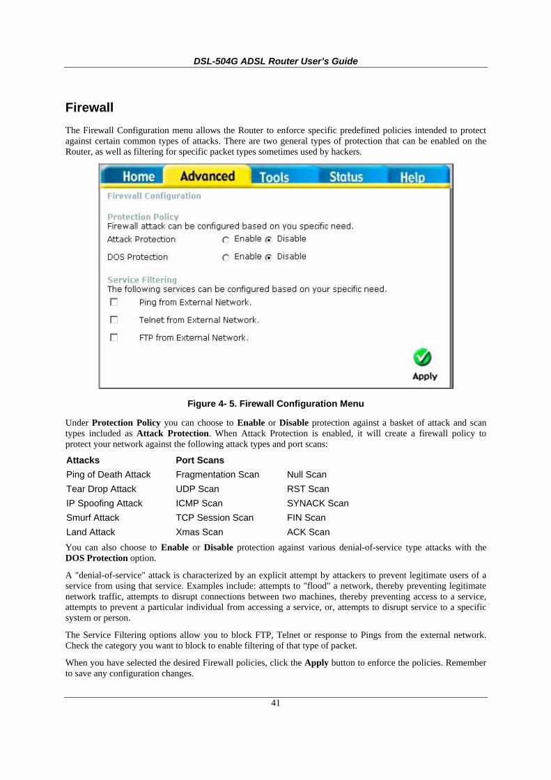
DSL-504G ADSL Router User’s Guide
41
Firewall The Firewall Configuration menu allows the Router to enforce specific predefined policies intended to protect against certain common types of attacks. There are two general types of protection that can be enabled on the Router, as well as filtering for specific packet types sometimes used by hackers.
Figure 4- 5. Firewall Configuration Menu
Under Protection Policy you can choose to Enable or Disable protection against a basket of attack and scan types included as Attack Protection. When Attack Protection is enabled, it will create a firewall policy to protect your network against the following attack types and port scans:
Attacks Port Scans Ping of Death Attack Tear Drop Attack IP Spoofing Attack Smurf Attack Land Attack
Fragmentation Scan UDP Scan ICMP Scan TCP Session Scan Xmas Scan
Null Scan RST Scan SYNACK Scan FIN Scan ACK Scan
You can also choose to Enable or Disable protection against various denial-of-service type attacks with the DOS Protection option.
A "denial-of-service" attack is characterized by an explicit attempt by attackers to prevent legitimate users of a service from using that service. Examples include: attempts to "flood" a network, thereby preventing legitimate network traffic, attempts to disrupt connections between two machines, thereby preventing access to a service, attempts to prevent a particular individual from accessing a service, or, attempts to disrupt service to a specific system or person.
The Service Filtering options allow you to block FTP, Telnet or response to Pings from the external network. Check the category you want to block to enable filtering of that type of packet.
When you have selected the desired Firewall policies, click the Apply button to enforce the policies. Remember to save any configuration changes.

DSL-504G ADSL Router User’s Guide
42
Static Routing Use the Static Routing Table to specify a route used for data traffic within your Ethernet LAN or to route data on the WAN. This is used to specify that all packets destined for a particular network or subnet use a predetermined gateway. If the DSL-500G is the only routing device on your network and the only gateway to the Internet, you do not need to use static routing. However, for particular networking arrangements it may be desirable. For example, if you are using another router, Layer 3 switch or similar gateway device on your LAN; or if you have setup a VPN tunnel to a remote LAN with its own gateway device, you may need to use this feature.
Figure 4-6. Static Routing menu
To add a static route to a specific destination IP address, enter a Destination IP address, Netask, and Gateway IP address. Click Apply to enter the new static route in the table below. The route becomes active immediately upon creation.
Existing static routes cannot be edited. To remove a static route, click on the trashcan icon for the static route. Remember to save the configuration changes.
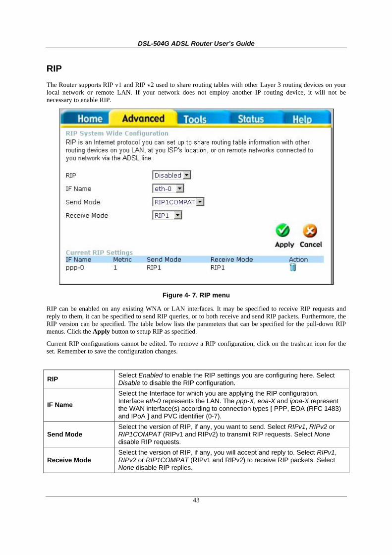
DSL-504G ADSL Router User’s Guide
43
RIP The Router supports RIP v1 and RIP v2 used to share routing tables with other Layer 3 routing devices on your local network or remote LAN. If your network does not employ another IP routing device, it will not be necessary to enable RIP.
Figure 4- 7. RIP menu
RIP can be enabled on any existing WNA or LAN interfaces. It may be specified to receive RIP requests and reply to them, it can be specified to send RIP queries, or to both receive and send RIP packets. Furthermore, the RIP version can be specified. The table below lists the parameters that can be specified for the pull-down RIP menus. Click the Apply button to setup RIP as specified.
Current RIP configurations cannot be edited. To remove a RIP configuration, click on the trashcan icon for the set. Remember to save the configuration changes.
RIP Select Enabled to enable the RIP settings you are configuring here. Select Disable to disable the RIP configuration.
IF Name Select the Interface for which you are applying the RIP configuration. Interface eth-0 represents the LAN. The ppp-X, eoa-X and ipoa-X represent the WAN interface(s) according to connection types [ PPP, EOA (RFC 1483) and IPoA ] and PVC identifier (0-7).
Send Mode Select the version of RIP, if any, you want to send. Select RIPv1, RIPv2 or RIP1COMPAT (RIPv1 and RIPv2) to transmit RIP requests. Select None disable RIP requests.
Receive Mode Select the version of RIP, if any, you will accept and reply to. Select RIPv1, RIPv2 or RIP1COMPAT (RIPv1 and RIPv2) to receive RIP packets. Select None disable RIP replies.

DSL-504G ADSL Router User’s Guide
44
ADSL Modulation Settings The default modulation technique used by the Router will automatically detect what ADSL protocol is used for your account. However it can be changed to any of the recognized standard modulations used for ADSL. Select the Modulation Type from the pull-down menu and click the Apply button to change the modulation.
Figure 4- 8. ADSL Modulation Configuration menu
PPP Settings When the WAN connection is configured for either PPPoA or PPPoE, you can configure the Router’s PPP session to remain on all the time, or to disconnect after some period of no activity. You may also choose to instruct the Router to connect each time you want to access the WAN or the Internet.
Figure 4- 9. PPP Connection settings menu
If you want the Internet or WAN connection to be available any time a host on your LAN requests access, select the Connect On Demand option and choose an idle time of 0 minutes..
If your ISP account is billed according to the amount of time the Router is connected, choose the Connection On Demand option and configure the idle time to 1 or more minutes. The idle time tell the Router to disconnect the PPP connection after a period of inactivity. This will discontinue the PPP session and require a few seconds to reconnect when a host requests access to the WAN. Alternatively you can choose the Manual option and use the Connect button to initiate a PPP connection each time you want to use the Router to access the WAN. If you use the Manual option, you must return to this menu and click the Disconnect button to terminate the PPP session.

DSL-504G ADSL Router User’s Guide
45
ATM VC The ATM Virtual Circuit connection menu is used to configure the WAN connection. If you are using multiple PVCs, you can change the configuration of any PVC in this menu.
This menu can be used as an alternative menu to configure the same settings found on the WAN menu in the Home directory.
Figure 4- 10. ATM Virtual Circuit configuration menu
To configure an existing PVC configuration set, click the corresponding notepad icon in the right-hand column of the ATM VCs List. The PVCs current settings appear above in the entry fields of the ATM VC Settings menu. Configure the appropriate settings and click the Apply button to put the new settings into effect.
To create new or additional PVCs, read the section below on Multiple PVCs.

DSL-504G ADSL Router User’s Guide
46
Multiple Virtual Connections The Router supports multiple virtual connections. Up to eight PVCs to eight separate destinations can be created and operated simultaneously utilizing the same bandwidth. Additional PVC connections can be added for various purposes. For example, you may want to establish a private connection to remote office in order to create an extended LAN, or setup a server on a separate connection. Provisioning for additional PVC profiles must be done through your telecommunications services provider. Extended LAN operations employing multiple virtual connections require ADSL routers or modems at the remote site for a successful connection. Contact your ISP or telecommunications service provider if you are interested in setting up multiple virtual connections.
After the necessary arrangements have been made to use the Router with multiple virtual connections, follow the instructions below to setup the Router using the VPI/VCI settings given to you by your server provider.
Configure Multiple PVCs Additional PVCs can be configured by first accessing the WAN configuration menu in the Home directory.
Figure 4- 11. Select new PVC to configure in the WAN menu
The PVC pull-down menu offers 8 virtual connections available for configuration. The default VC used by the Router is labeled Pvc0. Any additional connections that are configured must have a VPI/VCI combination that is unique to the Router. These numbers will have been already been established by your service provider on their network.
To add a new virtual connection:
1. Select the new PVC to configure from the pull-down menu.
2. Enter the values for the VPI and VCI given to you by your service provider.
3. To activate the VC, select Enabled from the Virtual Circuit pull-down menu.
4. Configure the WAN Settings and Connection Type as desired.

DSL-504G ADSL Router User’s Guide
47
In the example below, a new VC (Pvc1) has been added using the WAN Settings menu. The connection is setup as a bridged connection.
Figure 4- 12. Configure new VC
The new VC appears listed in the ATM VC Setting menu located in the Advanced directory.
Figure 4- 13. New VC listed in ATM VC Settings menu
Any VC may be configured in the ATM VC menu by clicking the notepad icon for the PVC you want to configure. VCs configured with PPP connection types can be further configured in the PPP menu.

DSL-504G ADSL Router User’s Guide
48
Tools and Utilities Click the Tools tab to reveal the menu buttons for various functions located in this directory. These menus are used to change the system password used to access the web manager, to save or load Router configuration settings, upgrade the device firmware, save current configuration settings, restore default settings, and to perform miscellaneous actions such performing Ping tests. These menus are described below.
Change System Password To change the password used to access the Router web manager, click the Admin button in the Tools directory. Type the New Password and Confirm Password to be certain you have typed it correctly. Click the Apply button to activate the new password. The System User Name (Login Name) remains “admin”, this cannot be changed using the web manager interface. Be sure to save the new setting (see below).
Figure 4- 14. Administrator Settings Menu

DSL-504G ADSL Router User’s Guide
49
Configure System Time Use the Time menu to configure the Router’s system time manually or from an SNTP server or your computer’s system clock.
Figure 4- 15. Time Settings Menu
If you opt to use the Automatic option you must have an IP address of an available SNTP server. Date settings use the format Year/Month/Date, Time settings use the format Hour (24 hour clock)/ Minute/ Second.
Click the Apply to set the Date and Time settings.

DSL-504G ADSL Router User’s Guide
50
Save Router Configuration Settings When you have completed configuration of the Router, make sure you save the current configuration settings to flash memory or risk losing the settings. To save the current configuration settings, click the Misc. menu button to view the Miscellaneous Configuration menu and click the Save and Reboot button. The current settings will be saved to NV-RAM and the system will restart. Do not turn off the Router during this process. It should take about two minutes to complete. After restarting, it is a good idea to backup the Router configuration file to your computer. See the instructions below to save configuration files to your PC.
Figure 4- 16. Miscellaneous Configuration Menu
Other functions available in this menu are a Ping test and IGMP enable/disable.
Ping Test The Ping test functions on the WAN and LAN interfaces. Type the IP address you want to check in the space provided and click the Ping button. Read the Ping test result in the space immediately below.
IGMP This is Disabled by default. This setting will not allow IGMP (Internet Group Management Protocol) packets to be forwarded to the LAN. IGMP is used to manage multicasting on TCP/IP networks, most users will not need to enable this. Some ISPs use IGMP to perform remote configuration for client devices, such as the Router. If you are unsure, check with your ISP. To enable IGMP service to the LAN interface, select Enabled and click the Apply button.

DSL-504G ADSL Router User’s Guide
51
Save Configuration File to PC Once you have configured the Router to your satisfaction, it is a good idea to back up the configuration file to your computer. Use the System Setting menu to save the existing configuration file to the hard drive of the system you are using to access the web manager. To save the system configuration file to your computer, click the Save button. You will be prompted to select a location on your computer to put the file. The file type is .cfg and may be named anything you wish.
Load Saved Configuration Files To load a previously saved configuration file, click the Browse button and locate the file on your computer. Or type the full path and file name of the .cfg file in the space provided. Click the Load button to begin transferring and loading the .cfg file to the Router. Confirm that you want to load the file when prompted and the process is completed automatically. The Router will reboot and begin operating with the configuration settings that have just been loaded.
Figure 4- 17. System Settings
Restore Factory Default Settings To reset the Router to its factory default settings, click the Restore button. You will be prompted to confirm your decision to reset the Router. The Router will reboot with the factory default settings including IP settings.

DSL-504G ADSL Router User’s Guide
52
Firmware Upgrade
Note
Performing a Firmware Upgrade can sometimes change the configuration settings. Be sure to back-up the Router’s configuration settings before upgrading the firmware.
Use the Firmware Upgrade menu to load the latest firmware for the device. Note that the device configuration settings may return to the factory default settings, so make sure you save the configuration settings with the System Settings menu described above.
Figure 4- 18. Firmware Upgrade
To upgrade firmware, type in the name and path of the file or click on the Browse button to search for the file. Click the Apply button to begin copying the file. The file will load and restart the Router automatically.

DSL-504G ADSL Router User’s Guide
53
Router Status Information Use the various read-only menus to view system information and monitor performance.
Device Information Display Use the Device Information window to quickly view basic current information about the LAN, WAN and Wireless interfaces. The basic information available in this window is summarized below.
LAN The MAC Address of the Ethernet LAN connection, IP Address, and Subnet Mask information will be displayed, as well as the setting (Enabled/Disabled) for the DHCP Server.
WAN (ADSL)
The MAC Address of the Ethernet WAN connection, IP Address, Subnet Mask, Default Gateway, and DNS (Domain Name Server) information will be listed. The connection type includes Dynamic, Static, and PPPoE. You may click the DHCP Release or Renew the IP address assigned by the ISP for the WAN port for the Dynamic Setting Option. For PPPoE setting, you may click the button to Connect and Disconnect the DSL connection.
Figure 4- 19. Display Information window

DSL-504G ADSL Router User’s Guide
54
ADSL Status Use the ADSL Status summary window for troubleshooting when problems occur with the ADSL connection.
Figure 4- 20. ADSL Line Condition
Log The log file keeps record of the events and activities occurring on the device. It can display up to 256 events. The latest activities will overwrite the outdated ones. When the device is rebooted, the logs are automatically cleared.
Figure 4- 21. View Log

DSL-504G ADSL Router User’s Guide
55
The log menu buttons in this function as follow:
First Page Display the first page of the log. Last Page Display the last page of the log. Previous Moves back one log page. Next Moves forward one log page. Clear Log Clears the logs completely. Save Log Save log file to your hard drive.
Traffic Statistics The device keeps statistic of the data traffic that it handles. You are able to read the amount of Receive and Transmit packets that pass through the device on the ADSL interface or Ethernet interface. Click the Refresh button to update the counters and the Reset button to clear the counters. The traffic counter will reset when the device is rebooted.
Figure 4- 22. Traffic Statistics

DSL-504G ADSL Router User’s Guide
56
A Technical Specifications
GENERAL
Standards & Protocols
ITU G.992.1 (G.dmt) Annex AITU G.992.2 (G.lite) Annex A ITU G.994.1 (G.Hs) ANSI T1.413 Issue # 2 TCP/IP UDP NAT RIP v1 (RFC 1058) RIP v2 (RFC 1389) IGMP ICMP
Classical IP over ATM (RFC1577) DHCP Server (RFC2131) DHCP Client (RFC2131) DHCP Relay (RFC2132) ARP AAL5 RFC1661 Point-to-Point Protocol RFC2364 PPP over ATM RFC2516 PPP over Ethernet RFC1483/2684 Bridged/Routed Ethernet over ATM RFC 1334 PAP RFC 1994 CHAP
Data Transfer Rate:
G.dmt full rate: Downstream up to 8 Mbps Upstream up to 864 Kbps G.lite: Downstream up to 1.5 Mbps Upstream up to 512 Kbps
Media Interface: RJ-11 port ADSL telephone line connection RJ-45 port for 10/100BASET Ethernet connection, MDI/MDIX Auto-sensing

DSL-504G ADSL Router User’s Guide
57
Physical and Environmental
DC Inputs: Power Adapter:
Input: 100V ~ 240V AC 50 ~ 60Hz Output: 12V AC, 1.2A
Power Consumption:
12 Watts (max)
Operating Temperature:
0° to 40° C (32° - 104° F)
Humidity: 5 to 95% (non-condensing) Dimensions: 180 x 141 x 30 mm Weight: 332 g EMI: CE Class B, FCC Class B (Part 15) Safety: CSA International Reliability: Mean Time Between Failure (MTBF) min. 4 years

DSL-504G ADSL Router User’s Guide
58
B Low Pass Filters Most ADSL clients will be required to install a simple device that prevents the ADSL line from interfering with regular telephone services. These devices are low pass filters and are variously referred to as in-line filters, micro-filters, line splitters or split line filters. They are easy to install and use standard telephone connectors and cable.
For some ADSL clients, a telecommunications technician will be sent to the client’s premises to modify the telephone line, usually at the point where the telephone line enters the building. If a technician has divided or split your telephone line into two separate lines - one for regular telephone service and the other for ADSL – then you do not need to use any type of filter device. Follow the instructions given to you by your ADSL service provider, ISP or telephone company about where and how you should connect the Router to the ADSL line.
In-Line Filters Two common styles of low pass filters are shown in this section, the first is an in-line filter and is illustrated in Figure 16 below. In-line filters are easy-to-install, in-line devices, which attach to the telephone cable between the telephone and wall jack.
In-line Filter Installation
Note: Do not install an in-line filter between the Router and the telephone jack. In-line filters are only intended for use with regular telephones, Fax machines and other regular telephone devices.

DSL-504G ADSL Router User’s Guide
59
Split Line Filter If you are instructed to use a split line style filter you must install the device between the Router and the phone jack. Use standard telephone cable with standard RJ-11 connectors. The splitter has three RJ-11 ports used to connect to the wall jack, the Router and if desired, a telephone or telephone device. The connection ports are typically labeled as follows:
Line - This port connects to the wall jack.
ADSL – This port connects to the Router.
Phone – This port connects to a telephone or other telephone device.
The diagram below illustrates the proper use of the split line style filter.
Split Line Filter Installation
DSL-504G


Offices Australia D-Link Australia 1 Giffnock Avenue, North Ryde, NSW 2113, Sydney, Australia TEL: 61-2-8899-1800 FAX: 61-2-8899-1868 TOLL FREE (Australia): 1300-766-868 TOLL FREE (New Zealand): 0800-900-900 URL: www.dlink.com.au E-MAIL: [email protected] & [email protected]
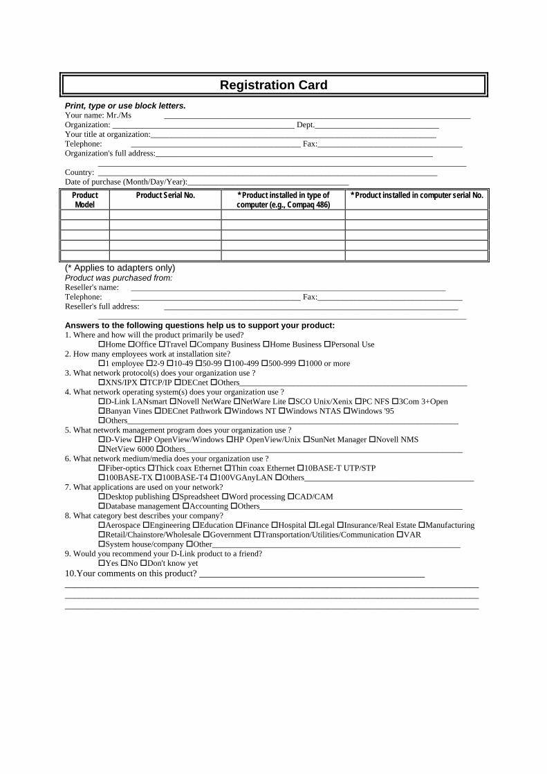
Registration Card Print, type or use block letters. Your name: Mr./Ms __________________________________________________________________________ Organization: ____________________________________________ Dept.______________________________ Your title at organization:_____________________________________________________________________ Telephone: _________________________________________ Fax:___________________________________ Organization's full address:___________________________________________________________________ _________________________________________________________________________________________ Country: __________________________________________________________________________________ Date of purchase (Month/Day/Year):_______________________________________
Product Model
Product Serial No. * Product installed in type of computer (e.g., Compaq 486)
* Product installed in computer serial No.
(* Applies to adapters only) Product was purchased from: Reseller's name: ____________________________________________________________________________ Telephone: _________________________________________ Fax:___________________________________ Reseller's full address: _______________________________________________________________________ _________________________________________________________________________________________ Answers to the following questions help us to support your product: 1. Where and how will the product primarily be used? Home Office Travel Company Business Home Business Personal Use 2. How many employees work at installation site? 1 employee 2-9 10-49 50-99 100-499 500-999 1000 or more 3. What network protocol(s) does your organization use ? XNS/IPX TCP/IP DECnet Others_______________________________________________________ 4. What network operating system(s) does your organization use ? D-Link LANsmart Novell NetWare NetWare Lite SCO Unix/Xenix PC NFS 3Com 3+Open Banyan Vines DECnet Pathwork Windows NT Windows NTAS Windows '95 Others________________________________________________________________________________ 5. What network management program does your organization use ? D-View HP OpenView/Windows HP OpenView/Unix SunNet Manager Novell NMS NetView 6000 Others___________________________________________________________________ 6. What network medium/media does your organization use ? Fiber-optics Thick coax Ethernet Thin coax Ethernet 10BASE-T UTP/STP 100BASE-TX 100BASE-T4 100VGAnyLAN Others_________________________________________ 7. What applications are used on your network? Desktop publishing Spreadsheet Word processing CAD/CAM Database management Accounting Others_________________________________________________ 8. What category best describes your company? Aerospace Engineering Education Finance Hospital Legal Insurance/Real Estate Manufacturing Retail/Chainstore/Wholesale Government Transportation/Utilities/Communication VAR System house/company Other____________________________________________________________ 9. Would you recommend your D-Link product to a friend? Yes No Don't know yet 10.Your comments on this product? _________________________________________________ ______________________________________________________________________________________________________________________________________________________________________________________________________________________________________________________________________________