DSH DS40 Stage TrussBS8118 part 1. 1991 Structural use of aluminium BS8118 part 2. 1991 Structural...
10
Daytona Stage Hire PO Box 43, Huddersfield, West Yorkshire, HD8 9YU T 01484 605555 M 07889 132580 Paul M 07764 588093 Kris W www.daytonastagehire.com E offi[email protected] DS40 Stage Truss General Information….. • All load calculations and technical information contained in this section have been sourced from Total Solutions Group Ltd who are the truss manufacturers and Scott White & Hookins LLP who we use for the structural manual, structural calculations and structural advise. • All load calculations in this section are subject to a safety factor, which takes into account the extra effects of the self weight of the roof panel, 3 off sodium work lights and the effects of rain. Guidelines….. • The truss manufacturers guidelines state that any load secured to the truss should only be attached on the main chords (50mm tube) at the node points (V section), using purpose made connectors with a secondary safety chain or steel rope. • The truss may only be rigged by competent, and suitably experienced people/organisations that have the relevant experience of structures of this type. • It is the responsibility of the Event Organiser or their on site representative to ensure that the following load limits and guidelines are strictly complied with. Failure to adhere to these guidelines may severely compromise Health & Safety issues associated with this type of structure. Therefore, Daytona Stage Hire shall not be held responsible for any damage or consequential loss if these guidelines and load calculations are broken. Furthermore, should damage occur to any of Daytona Stage Hire’s equipment or staff as a direct result of breaking these guidelines, the Event Organiser or their on site representative shall be held responsible
Transcript of DSH DS40 Stage TrussBS8118 part 1. 1991 Structural use of aluminium BS8118 part 2. 1991 Structural...
Daytona Stage HirePO Box 43, Huddersfield, West Yorkshire, HD8 9YU
T 01484 605555 M 07889 132580 Paul M 07764 588093 KrisW www.daytonastagehire.com E [email protected]
DS40 Stage TrussGeneral Information…..• All load calculations and technical information contained in this section have been sourced from
Total Solutions Group Ltd who are the truss manufacturers and Scott White & Hookins LLP who we use for the structural manual, structural calculations and structural advise.
• All load calculations in this section are subject to a safety factor, which takes into account the extra effects of the self weight of the roof panel, 3 off sodium work lights and the effects of rain.
Guidelines…..• The truss manufacturers guidelines state that any load secured to the truss should only be
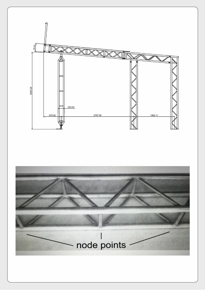
attached on the main chords (50mm tube) at the node points (V section), using purpose made connectors with a secondary safety chain or steel rope.
• The truss may only be rigged by competent, and suitably experienced people/organisations that have the relevant experience of structures of this type.
• It is the responsibility of the Event Organiser or their on site representative to ensure that the following load limits and guidelines are strictly complied with. Failure to adhere to these guidelines may severely compromise Health & Safety issues associated with this type of structure. Therefore, Daytona Stage Hire shall not be held responsible for any damage or consequential loss if these guidelines and load calculations are broken. Furthermore, should damage occur to any of Daytona Stage Hire’s equipment or staff as a direct result of breaking these guidelines, the Event Organiser or their on site representative shall be held responsible
DS40 Stage Truss continued
Specification…..• DS40 stage uses a combination of quad and ladder trussing, both types are manufactured by
Total Solutions Group Ltd to Daytona Stage Hire dimension requirements.
• Truss Material Type: 6082-T6 Aluminium alloy with corresponding filler wire grade 4043-A.
• Materials Standards: BS EN755-2. 1997 Aluminium and aluminium alloys BS2901-4. 1990 Filler rods and wires for gas shielded arc welding.
• Manufacturing Standards: BS8118 part 1. 1991 Structural use of aluminium BS8118 part 2. 1991 Structural use of aluminium BS6399 loading for buildings BS7905-2. 2000 Lifting equipment for performance, broadcast and similar operations BS EN287-2. 1992 Approval testing of welders for fusion welding BS EN288-4. 1992 Specification and approval of welding procedures for metallic materials BS EN288-8. 1995 Specification and approval of welding procedures for metallic materials.
Loadings…..• Loadings for quad trussing per left to right 7.8m span. 1028kgs uniform distributed load. 514kgs central point load. 385kgs triple point load. 257kgs quarter point load.
• Loadings for ladder trussing per left to right 7.8m span. 349kgs uniform distributed load. 174kgs central point load. kgs triple point load. 131kgs quarter point load.
• Loadings overall 2075kgs.
• Whenever chain motors are used, the above load figures must be divided by 1.25, this will provide a safety margin to counter the ‘snatch’ factor common to this equipment.
• The manufacturers load calculations are on page 3 & 4.
• The basic plan of the stage trussing is on page 5.

STRUCTURAL REPORT ON OV30L LADDER TRUSS Project Ref 111627Revision 1
July 2013 Page 1 of 45
SUMMARY OF LOAD CAPACITIES.
The following table summarises the allowable loads on spans up to 12 metres.
Span 3.0 6.0 9.0 12.0m m m m
Uniformlydistributed
kg 2460 673 349 217kN 24.12 6.60 3.42 2.13
Central point load kg 1230 336 174 108kN 12.06 3.30 1.71 1.06
Quarter point loadsat each point
kgkN 6.03 1.65 0.86 0.53
Third point loadsat each point
kg 922 252 131 82kN 9.04 2.47 1.28 0.80
Notes:x All loads are given in kilograms and kilonewtonsx All loads are applied symmetricallyx Allowance has been made for self-weight of trussx Allowance has been made for frequent use factor of 83%x The payload on a truss has been calculated as a permanent action. Should it be
necessary to consider the payload as a variable action, the tabulated figuresshould be reduced to 90% of the given values.
x All spans must be effectively laterally restrained at a maximum of 2 metrecentres
Scott White and Hookins LLP Fountain House 26 St John’s Street Bedford Bedfordshire MK42 0AQ T +44 (0)1234 213111 [email protected]
Light Duty Truss, Total Solutions B01356
Prepared by: .............................................. Erika Espinosa MEng Reviewed by: .............................................. Doug Alcock BEng(Tech) CEng MICE MIStructE FConsE
Light Duty Truss Structural Report Total Solutions January 2016