DS1116 Mv Series for use with Novec 1230 Fluid · The Janus Fire Systems® Mv Series Clean Agent...
10
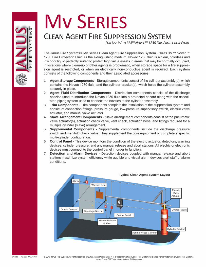
DS1116 Revised: 07-Jun-2010 The Janus Fire Systems® Mv Series Clean Agent Fire Suppression System utilizes 3M™ Novec™ 1230 Fire Protection Fluid as the extinguishing medium. Novec 1230 fluid is a clear, colorless and low odor liquid perfectly suited to protect high value assets in areas that may be normally occupied, in locations where clean-up of other agents is problematic, when storage space for a fire suppres- sion agent is restricted, or when an electrically non-conductive agent is required. Each system consists of the following components and their associated accessories: 1. Agent Storage Components - Storage components consist of the cylinder assembly(s), which contains the Novec 1230 fluid, and the cylinder bracket(s), which holds the cylinder assembly securely in place. 2. Agent Fluid Distribution Components - Distribution components consist of the discharge nozzles used to introduce the Novec 1230 fluid into a protected hazard along with the associ- ated piping system used to connect the nozzles to the cylinder assembly. 3. Trim Components - Trim components complete the installation of the suppression system and consist of connection fittings, pressure gauge, low-pressure supervisory switch, electric valve actuator, and manual valve actuator. 4. Slave Arrangement Components - Slave arrangement components consist of the pneumatic valve actuator(s), actuation check valve, vent check, actuation hose, and fittings required for a multiple cylinder (slave) arrangement. 5. Supplemental Components - Supplemental components include the discharge pressure switch and manifold check valve. They supplement the core equipment or complete a specific multi-cylinder configuration. 6. Control Panel - This device monitors the condition of the electric actuator, detectors, warning devices, cylinder pressure, and any manual release and abort stations. All electric or electronic devices must connect to the control panel in order to function. 7. Detection and Alarm Devices - Detection devices coupled with manual release and abort stations maximize system efficiency while audible and visual alarm devices alert staff of alarm conditions. Agent Storage Cylinder Cylinder Valve Cylinder Bracket Electric Valve Actuator Manual Release & Abort Smoke Detector Warning Sign Alarm Typical Clean Agent System Layout Discharge Nozzle Control Panel © 2010 Janus Fire Systems. All rights reserved (6/2010) Janus Design Suite™ is a trademark of and Janus Fire Systems® is a registered trademark of Janus Fire Systems. Novec™ and 3M™ are trademarks of 3M Company. Mv S ERIES Clean Agent Fire Suppression System For Use With 3M™ Novec™ 1230 Fire Protection Fluid
Transcript of DS1116 Mv Series for use with Novec 1230 Fluid · The Janus Fire Systems® Mv Series Clean Agent...
DS1116 Revised: 07-Jun-2010
The Janus Fire Systems® Mv Series Clean Agent Fire Suppression System utilizes 3M™ Novec™ 1230 Fire Protection Fluid as the extinguishing medium. Novec 1230 fluid is a clear, colorless and low odor liquid perfectly suited to protect high value assets in areas that may be normally occupied, in locations where clean-up of other agents is problematic, when storage space for a fire suppres-sion agent is restricted, or when an electrically non-conductive agent is required. Each system consists of the following components and their associated accessories:
1. Agent Storage Components - Storage components consist of the cylinder assembly(s), which contains the Novec 1230 fluid, and the cylinder bracket(s), which holds the cylinder assembly securely in place.
2. Agent Fluid Distribution Components - Distribution components consist of the discharge nozzles used to introduce the Novec 1230 fluid into a protected hazard along with the associ-ated piping system used to connect the nozzles to the cylinder assembly.
3. Trim Components - Trim components complete the installation of the suppression system and consist of connection fittings, pressure gauge, low-pressure supervisory switch, electric valve actuator, and manual valve actuator.
4. Slave Arrangement Components - Slave arrangement components consist of the pneumatic valve actuator(s), actuation check valve, vent check, actuation hose, and fittings required for a multiple cylinder (slave) arrangement.
5. Supplemental Components - Supplemental components include the discharge pressure switch and manifold check valve. They supplement the core equipment or complete a specific multi-cylinder configuration.
6. Control Panel - This device monitors the condition of the electric actuator, detectors, warning devices, cylinder pressure, and any manual release and abort stations. All electric or electronic devices must connect to the control panel in order to function.
7. Detection and Alarm Devices - Detection devices coupled with manual release and abort stations maximize system efficiency while audible and visual alarm devices alert staff of alarm conditions.
Agent Storage Cylinder
Cylinder Valve
Cylinder Bracket
ElectricValve
Actuator
Manual Release& Abort
Smoke Detector
Warning SignAlarm
Typical Clean Agent System Layout
Discharge Nozzle
Control Panel
© 2010 Janus Fire Systems. All rights reserved (6/2010) Janus Design Suite™ is a trademark of and Janus Fire Systems® is a registered trademark of Janus Fire Systems.Novec™ and 3M™ are trademarks of 3M Company.
Mv SERIESClean Agent Fire Suppression System
For Use With 3M™ Novec™ 1230 Fire Protection Fluid
DS1116 Revised: 07-Jun-2010
Fire suppression systems utilizing Novec 1230 fluid are designed in accordance with National Fire Protection Association (NFPA) 2001 - Standard on Clean Agent Fire Extinguishing Systems, which states each system shall be total flooding, meaning it discharges Novec 1230 fluid into a room, area, or enclosure with the structural integrity to retain the agent, and that each system discharges within 10 seconds with the Novec 1230 fluid becoming thoroughly mixed throughout the protected area, reach-ing a minimum concentration level of 4.2%, but not exceeding 10% in normally occupied areas.
EQUIPMENT DESCRIPTION
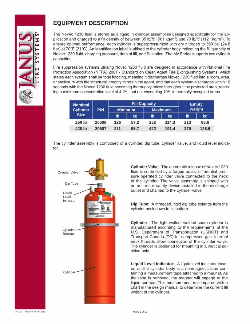
The Novec 1230 fluid is stored as a liquid in cylinder assemblies designed specifically for the ap-plication and charged to a fill density of between 35 lb/ft3 (561 kg/m3) and 70 lb/ft3 (1121 kg/m3). To ensure optimal performance, each cylinder is superpressurized with dry nitrogen to 360 psi (24.8 bar) at 70°F (21°C). An identification label is affixed to the cylinder body indicating the fill quantity of Novec 1230 fluid, charging pressure, date of fill, and fill station. The Mv Series supports two cylinder capacities.
Cylinder Valve: The automatic release of Novec 1230 fluid is controlled by a forged brass, differential pres-sure operated cylinder valve connected to the neck of the cylinder. The valve assembly is shipped with an anti-recoil safety device installed in the discharge outlet and chained to the cylinder valve.
Dip Tube: A threaded, rigid dip tube extends from the cylinder neck down to its bottom.
Cylinder: The light walled, welded seam cylinder is manufactured according to the requirements of the U.S. Department of Transportation (USDOT) and Transport Canada (TC) for compressed gas. Internal neck threads allow connection of the cylinder valve. The cylinder is designed for mounting in a vertical po-sition only.
The cylinder assembly is composed of a cylinder, dip tube, cylinder valve, and liquid level indica-tor.
Nominal Cylinder
SizeP/N
Fill Capacity EmptyWeightMinimum Maximum
lb kg lb kg lb kg250 lb 20506 126 57.2 252 114.3 213 96.6420 lb 20507 211 95.7 422 191.4 279 126.6
Liquid Level Indicator: A liquid level indicator locat-ed on the cylinder body is a nonmagnetic tube con-taining a measurement tape attached to a magnet. As the tape is removed, the magnet will engage at the liquid surface. This measurement is compared with a chart in the design manual to determine the current fill weight of the cylinder.
Page 2 of 10
Cylinder Valve
LiquidLevel Indicator
Dip Tube
Cylinder
CylinderBracket
DS1116 Revised: 07-Jun-2010
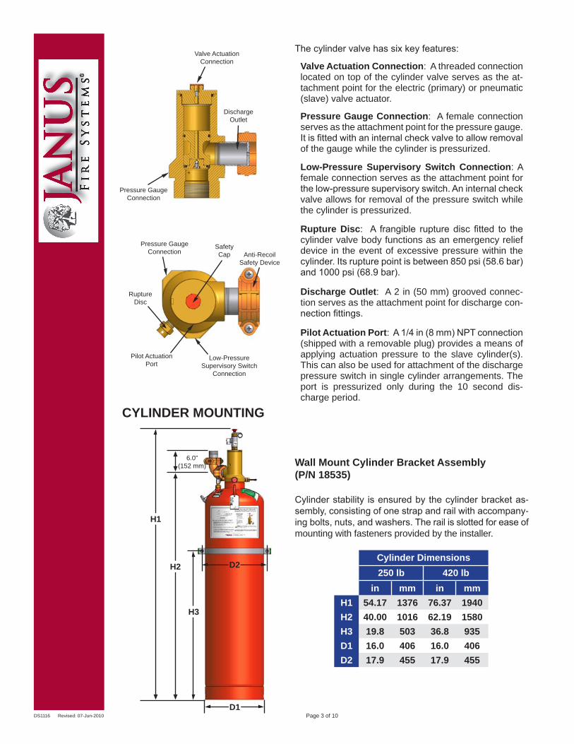
CYLINDER MOUNTING
Wall Mount Cylinder Bracket Assembly(P/N 18535)
Cylinder stability is ensured by the cylinder bracket as-sembly, consisting of one strap and rail with accompany-ing bolts, nuts, and washers. The rail is slotted for ease of mounting with fasteners provided by the installer.
Cylinder Dimensions250 lb 420 lb
in mm in mmH1 54.17 1376 76.37 1940H2 40.00 1016 62.19 1580H3 19.8 503 36.8 935D1 16.0 406 16.0 406D2 17.9 455 17.9 455
The cylinder valve has six key features:
Valve Actuation Connection: A threaded connection located on top of the cylinder valve serves as the at-tachment point for the electric (primary) or pneumatic (slave) valve actuator.
Pressure Gauge Connection: A female connection serves as the attachment point for the pressure gauge. It is fitted with an internal check valve to allow removal of the gauge while the cylinder is pressurized.
Low-Pressure Supervisory Switch Connection: A female connection serves as the attachment point for the low-pressure supervisory switch. An internal check valve allows for removal of the pressure switch while the cylinder is pressurized.
Rupture Disc: A frangible rupture disc fitted to the cylinder valve body functions as an emergency relief device in the event of excessive pressure within the cylinder. Its rupture point is between 850 psi (58.6 bar) and 1000 psi (68.9 bar).
Discharge Outlet: A 2 in (50 mm) grooved connec-tion serves as the attachment point for discharge con-nection fittings.
Pilot Actuation Port: A 1/4 in (8 mm) NPT connection (shipped with a removable plug) provides a means of applying actuation pressure to the slave cylinder(s). This can also be used for attachment of the discharge pressure switch in single cylinder arrangements. The port is pressurized only during the 10 second dis-charge period.
Page 3 of 10
H1
H2
H3
D1
D2
Valve Actuation Connection
DischargeOutlet
Pressure GaugeConnection
Pressure GaugeConnection Anti-Recoil
Safety Device
Low-PressureSupervisory Switch
Connection
Pilot ActuationPort
SafetyCap
RuptureDisc
6.0”(152 mm)
DS1116 Revised: 07-Jun-2010
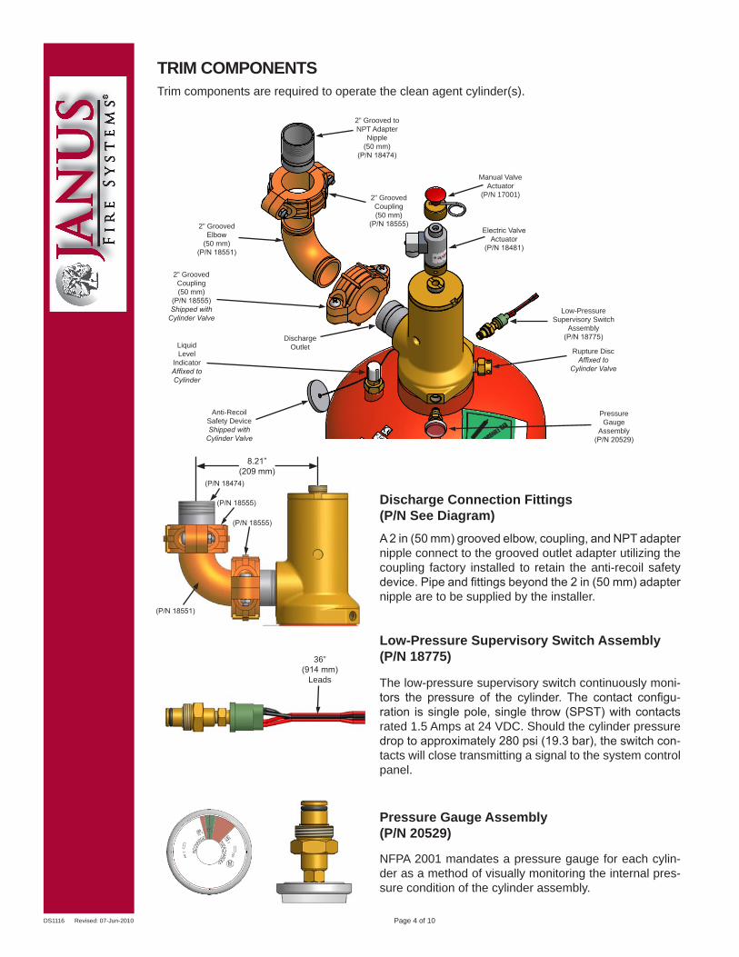
Discharge Connection Fittings(P/N See Diagram)A 2 in (50 mm) grooved elbow, coupling, and NPT adapter nipple connect to the grooved outlet adapter utilizing the coupling factory installed to retain the anti-recoil safety device. Pipe and fittings beyond the 2 in (50 mm) adapter nipple are to be supplied by the installer.
Pressure Gauge Assembly(P/N 20529)
NFPA 2001 mandates a pressure gauge for each cylin-der as a method of visually monitoring the internal pres-sure condition of the cylinder assembly.
TRIM COMPONENTS
Low-Pressure Supervisory Switch Assembly (P/N 18775)
The low-pressure supervisory switch continuously moni-tors the pressure of the cylinder. The contact configu-ration is single pole, single throw (SPST) with contacts rated 1.5 Amps at 24 VDC. Should the cylinder pressure drop to approximately 280 psi (19.3 bar), the switch con-tacts will close transmitting a signal to the system control panel.
DischargeOutlet
Electric ValveActuator
(P/N 18481)
Manual ValveActuator
(P/N 17001)
Rupture DiscAffixed to
Cylinder Valve
Low-PressureSupervisory Switch
Assembly(P/N 18775)
PressureGauge
Assembly(P/N 20529)
Trim components are required to operate the clean agent cylinder(s).
Page 4 of 10
2” GroovedCoupling(50 mm)
(P/N 18555)Shipped with
Cylinder Valve
2” GroovedElbow
(50 mm)(P/N 18551)
2” GroovedCoupling(50 mm)
(P/N 18555)
2” Grooved to NPT Adapter
Nipple(50 mm)
(P/N 18474)
LiquidLevel
IndicatorAffixed toCylinder
Anti-RecoilSafety DeviceShipped with
Cylinder Valve
(P/N 18474)
(P/N 18555)
(P/N 18551)
36”(914 mm)
Leads
8.21”(209 mm)
(P/N 18555)
DS1116 Revised: 07-Jun-2010
Typical Primary and Slave Cylinder Arrangement
DischargePressure Switch
(P/N 18773)
Pilot ActuationCheck Valve(P/N 18560)
PrimaryCylinder
ManualValve Actuator(P/N 17001)
ElectricValve Actuator(P/N 18481)
PneumaticValve Actuator(P/N 17019)
Discharge Manifold(Provided By Installer)
Pilot ActuationMid Line Tee(P/N 18622)
2” (50 mm) Manifold
Check Valve(P/N 18546) Vent Check
(P/N 10173)
24” Flex Hose (610 mm)
(P/N 18649)
Page 5 of 10
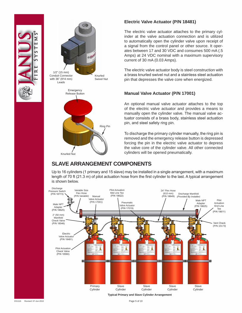
The electric valve actuator attaches to the primary cyl-inder at the valve actuation connection and is utilized to automatically open the cylinder valve upon receipt of a signal from the control panel or other source. It oper-ates between 17 and 30 VDC and consumes 500 mA (.5 Amps) at 24 VDC nominal with a maximum supervisory current of 30 mA (0.03 Amps).
Electric Valve Actuator (P/N 18481)
The electric valve actuator body is steel construction with a brass knurled swivel nut and a stainless steel actuation pin that depresses the valve core when energized.
Manual Valve Actuator (P/N 17001)Emergency
Release Button
Ring Pin
Knurled Nut
To discharge the primary cylinder manually, the ring pin is removed and the emergency release button is depressed forcing the pin in the electric valve actuator to depress the valve core of the cylinder valve. All other connected cylinders will be opened pneumatically.
An optional manual valve actuator attaches to the top of the electric valve actuator and provides a means to manually open the cylinder valve. The manual valve ac-tuator consists of a brass body, stainless steel actuation pin, and steel safety ring pin.
1/2” (15 mm)Conduit Connector with 36” (914 mm)
Leads
KnurledSwivel Nut
SlaveCylinder
SlaveCylinder
SlaveCylinder
SlaveCylinder
Male NPTAdapter
(P/N 18625)
PilotActuationEnd Line
Tee(P/N 18611)
Male NPTAdapter
(P/N 18625)
Variable SizeFlex Hose
(P/N Variable)
SLAVE ARRANGEMENT COMPONENTSUp to 16 cylinders (1 primary and 15 slave) may be installed in a single arrangement, with a maximum length of 70 ft (21.3 m) of pilot actuation hose from the first cylinder to the last. A typical arrangement is shown below.
DS1116 Revised: 07-Jun-2010 Page 6 of 10
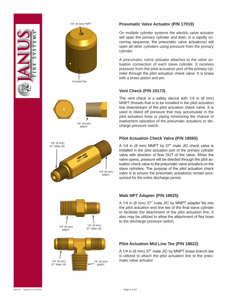
Vent Check (P/N 10173)
The vent check is a safety device with 1/4 in (8 mm) MNPT threads that is to be installed in the pilot actuation line downstream of the pilot actuation check valve. It is used to bleed off pressure that may accumulate in the pilot actuation hose or piping minimizing the chance of inadvertent operation of the pneumatic actuators or dis-charge pressure switch.
1/4” (8 mm) FNPT
Knurled Nut
Pneumatic Valve Actuator (P/N 17019)
A pneumatic valve actuator attaches to the valve ac-tuation connection of each slave cylinder. It receives pressure from the pilot actuation port of the primary cyl-inder through the pilot actuation check valve. It is brass with a brass piston and pin.
On multiple cylinder systems the electric valve actuator will open the primary cylinder and then, in a rapidly oc-curring sequence, the pneumatic valve actuator(s) will open all other cylinders using pressure from the primary cylinder.
Pilot Actuation Check Valve (P/N 18560)
A 1/4 in (8 mm) MNPT by 37° male JIC check valve is installed in the pilot actuation port of the primary cylinder valve with direction of flow OUT of the valve. When the valve opens, pressure will be directed through the pilot ac-tuation check valve to the pneumatic valve actuators on the slave cylinders. The purpose of the pilot actuation check valve is to ensure the pneumatic actuator(s) remain pres-surized for the entire discharge period.
Male NPT Adapter (P/N 18625)
A 1/4 in (8 mm) 37° male JIC by MNPT adapter fits into the pilot actuation end line tee of the final slave cylinder to facilitate the attachment of the pilot actuation line. It also may be utilized to allow the attachment of flex hose to the discharge pressure switch.
Pilot Actuation Mid Line Tee (P/N 18622)
A 1/4 in (8 mm) 37° male JIC by MNPT brass branch tee is utilized to attach the pilot actuation line to the pneu-matic valve actuator.1/4” (8 mm)
37° Male JIC1/4” (8 mm)
MNPT
1/4” (8 mm)37° Male JIC
1/4” (8 mm)MNPT
1/4” (8 mm)MNPT
1/4” (8 mm)MNPT
1/4” (8 mm)37° Male JIC
DS1116 Revised: 07-Jun-2010
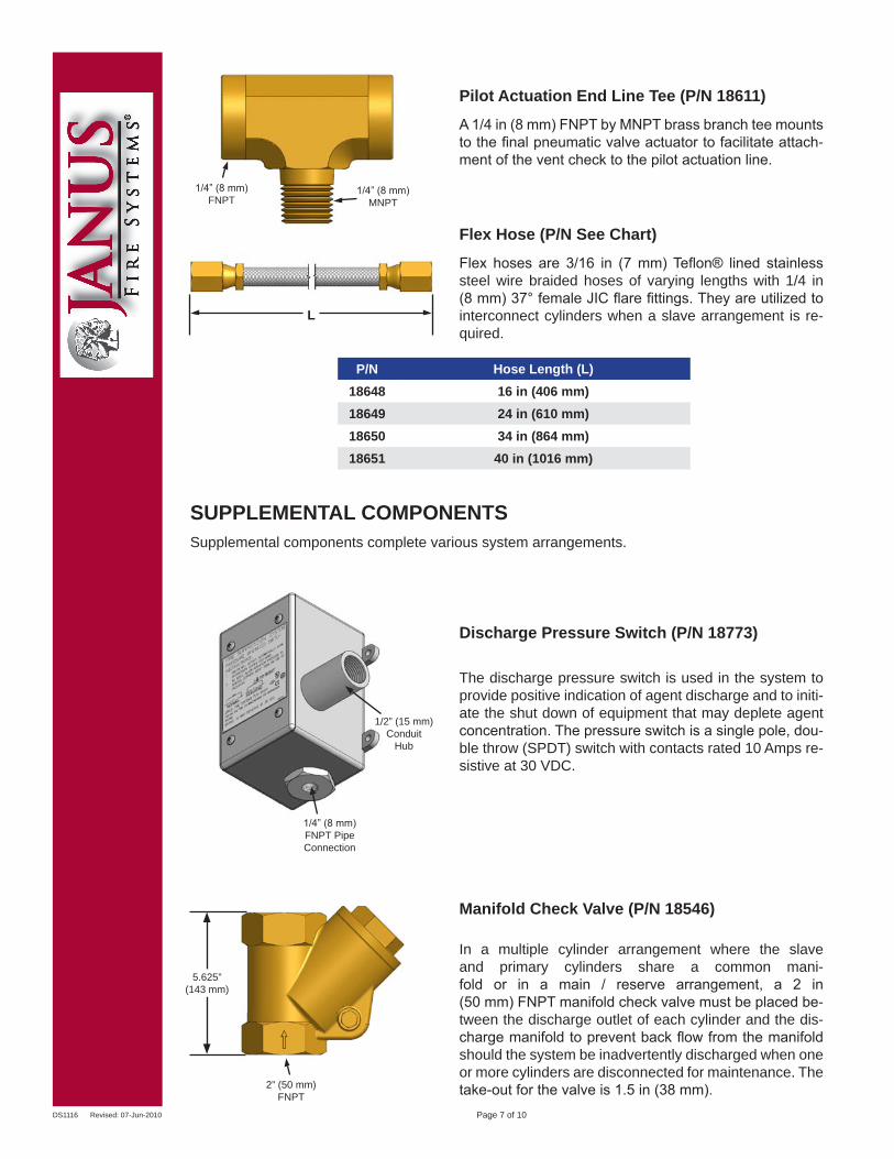
The discharge pressure switch is used in the system to provide positive indication of agent discharge and to initi-ate the shut down of equipment that may deplete agent concentration. The pressure switch is a single pole, dou-ble throw (SPDT) switch with contacts rated 10 Amps re-sistive at 30 VDC.
Discharge Pressure Switch (P/N 18773)
Manifold Check Valve (P/N 18546)
Page 7 of 10
In a multiple cylinder arrangement where the slave and primary cylinders share a common mani-fold or in a main / reserve arrangement, a 2 in (50 mm) FNPT manifold check valve must be placed be-tween the discharge outlet of each cylinder and the dis-charge manifold to prevent back flow from the manifold should the system be inadvertently discharged when one or more cylinders are disconnected for maintenance. The take-out for the valve is 1.5 in (38 mm).
SUPPLEMENTAL COMPONENTSSupplemental components complete various system arrangements.
Flex Hose (P/N See Chart)
Flex hoses are 3/16 in (7 mm) Teflon® lined stainless steel wire braided hoses of varying lengths with 1/4 in (8 mm) 37° female JIC flare fittings. They are utilized to interconnect cylinders when a slave arrangement is re-quired.
1/2” (15 mm) Conduit
Hub
1/4” (8 mm)FNPT PipeConnection
Pilot Actuation End Line Tee (P/N 18611)
A 1/4 in (8 mm) FNPT by MNPT brass branch tee mounts to the final pneumatic valve actuator to facilitate attach-ment of the vent check to the pilot actuation line.
P/N Hose Length (L)18648 16 in (406 mm)18649 24 in (610 mm)18650 34 in (864 mm)18651 40 in (1016 mm)
L
2” (50 mm)FNPT
1/4” (8 mm)FNPT
1/4” (8 mm)MNPT
5.625”(143 mm)
DS1116 Revised: 07-Jun-2010 Page 8 of 10
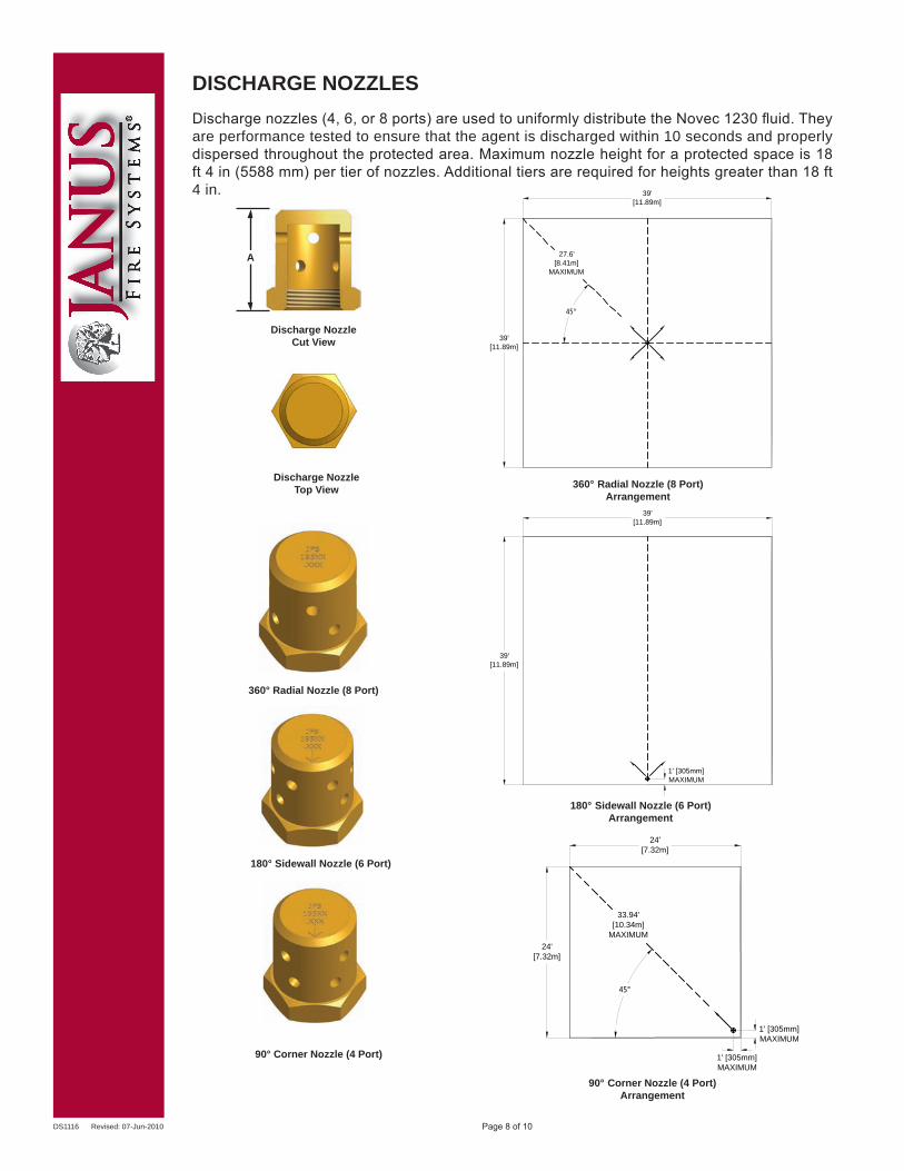
Discharge nozzles (4, 6, or 8 ports) are used to uniformly distribute the Novec 1230 fluid. They are performance tested to ensure that the agent is discharged within 10 seconds and properly dispersed throughout the protected area. Maximum nozzle height for a protected space is 18 ft 4 in (5588 mm) per tier of nozzles. Additional tiers are required for heights greater than 18 ft 4 in.
DISCHARGE NOZZLES
A
360° Radial Nozzle (8 Port)Arrangement
180° Sidewall Nozzle (6 Port)Arrangement
90° Corner Nozzle (4 Port)Arrangement
24'[7.32m]
24'[7.32m]
45°
1' [305mm]MAXIMUM
1' [305mm]MAXIMUM
33.94'[10.34m]
MAXIMUM
27.6' [8.41m]
MAXIMUM
39'[11.89m]
39'[11.89m]
39'[11.89m]
39'[11.89m]
1' [305mm]MAXIMUM
45°
24'[7.32m]
24'[7.32m]
45°
1' [305mm]MAXIMUM
1' [305mm]MAXIMUM
33.94'[10.34m]
MAXIMUM
27.6' [8.41m]
MAXIMUM
39'[11.89m]
39'[11.89m]
39'[11.89m]
39'[11.89m]
1' [305mm]MAXIMUM
45°
24'[7.32m]
24'[7.32m]
45°
1' [305mm]MAXIMUM
1' [305mm]MAXIMUM
33.94'[10.34m]
MAXIMUM
27.6' [8.41m]
MAXIMUM
39'[11.89m]
39'[11.89m]
39'[11.89m]
39'[11.89m]
1' [305mm]MAXIMUM
45°
360° Radial Nozzle (8 Port)
90° Corner Nozzle (4 Port)
180° Sidewall Nozzle (6 Port)
Discharge Nozzle Cut View
Discharge NozzleTop View
DS1116 Revised: 07-Jun-2010 Page 9 of 10
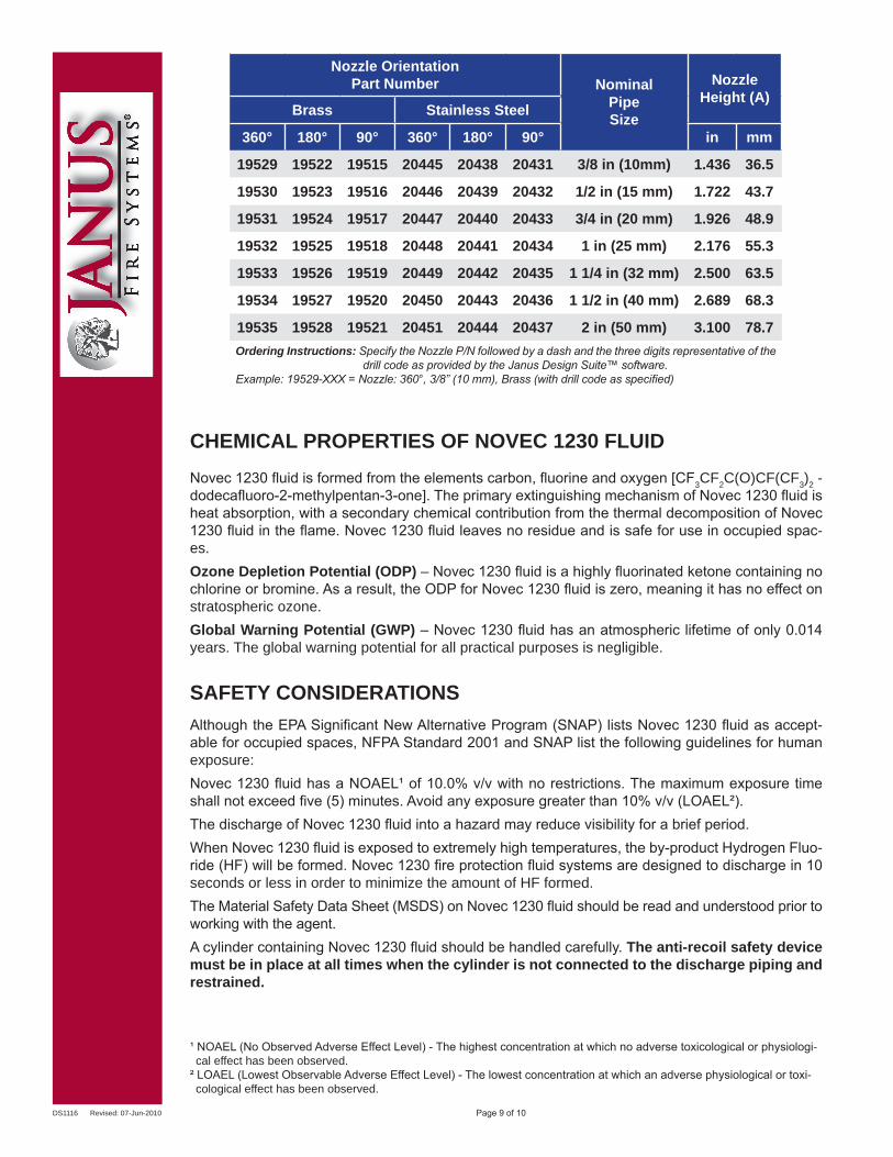
Nozzle OrientationPart Number Nominal
PipeSize
Nozzle Height (A)
Brass Stainless Steel
360° 180° 90° 360° 180° 90° in mm
19529 19522 19515 20445 20438 20431 3/8 in (10mm) 1.436 36.5
19530 19523 19516 20446 20439 20432 1/2 in (15 mm) 1.722 43.7
19531 19524 19517 20447 20440 20433 3/4 in (20 mm) 1.926 48.9
19532 19525 19518 20448 20441 20434 1 in (25 mm) 2.176 55.3
19533 19526 19519 20449 20442 20435 1 1/4 in (32 mm) 2.500 63.5
19534 19527 19520 20450 20443 20436 1 1/2 in (40 mm) 2.689 68.3
19535 19528 19521 20451 20444 20437 2 in (50 mm) 3.100 78.7Ordering Instructions: Specify the Nozzle P/N followed by a dash and the three digits representative of the
drill code as provided by the Janus Design Suite™ software.Example: 19529-XXX = Nozzle: 360°, 3/8” (10 mm), Brass (with drill code as specified)
Although the EPA Significant New Alternative Program (SNAP) lists Novec 1230 fluid as accept-able for occupied spaces, NFPA Standard 2001 and SNAP list the following guidelines for human exposure:Novec 1230 fluid has a NOAEL¹ of 10.0% v/v with no restrictions. The maximum exposure time shall not exceed five (5) minutes. Avoid any exposure greater than 10% v/v (LOAEL²).The discharge of Novec 1230 fluid into a hazard may reduce visibility for a brief period.When Novec 1230 fluid is exposed to extremely high temperatures, the by-product Hydrogen Fluo-ride (HF) will be formed. Novec 1230 fire protection fluid systems are designed to discharge in 10 seconds or less in order to minimize the amount of HF formed.The Material Safety Data Sheet (MSDS) on Novec 1230 fluid should be read and understood prior to working with the agent.A cylinder containing Novec 1230 fluid should be handled carefully. The anti-recoil safety device must be in place at all times when the cylinder is not connected to the discharge piping and restrained.
SAFETY CONSIDERATIONS
Novec 1230 fluid is formed from the elements carbon, fluorine and oxygen [CF3CF2C(O)CF(CF3)2 - dodecafluoro-2-methylpentan-3-one]. The primary extinguishing mechanism of Novec 1230 fluid is heat absorption, with a secondary chemical contribution from the thermal decomposition of Novec 1230 fluid in the flame. Novec 1230 fluid leaves no residue and is safe for use in occupied spac-es.Ozone Depletion Potential (ODP) – Novec 1230 fluid is a highly fluorinated ketone containing no chlorine or bromine. As a result, the ODP for Novec 1230 fluid is zero, meaning it has no effect on stratospheric ozone.Global Warning Potential (GWP) – Novec 1230 fluid has an atmospheric lifetime of only 0.014 years. The global warning potential for all practical purposes is negligible.
CHEMICAL PROPERTIES OF NOVEC 1230 FLUID
¹ NOAEL (No Observed Adverse Effect Level) - The highest concentration at which no adverse toxicological or physiologi-cal effect has been observed.
² LOAEL (Lowest Observable Adverse Effect Level) - The lowest concentration at which an adverse physiological or toxi-cological effect has been observed.
DS1116 Revised: 07-Jun-2010
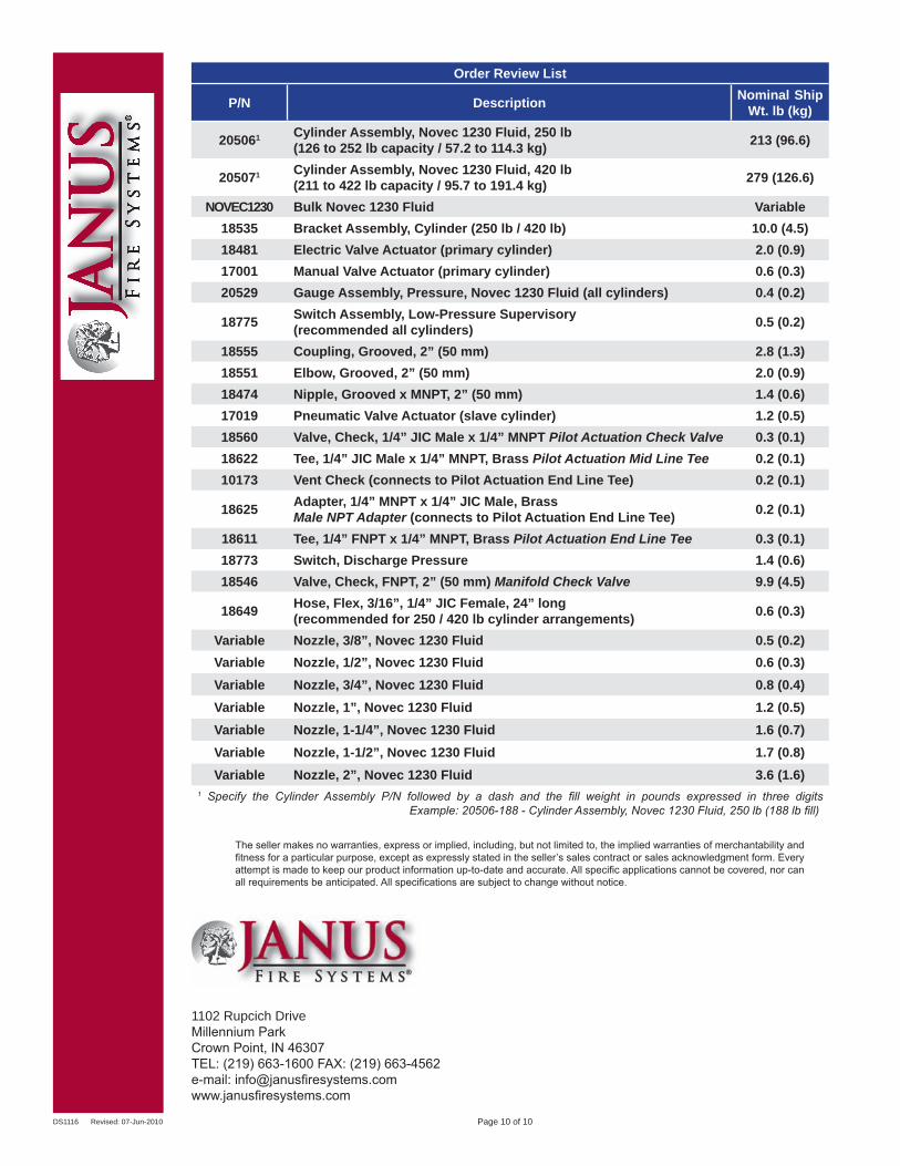
Order Review List
P/N Description Nominal Ship Wt. lb (kg)
205061 Cylinder Assembly, Novec 1230 Fluid, 250 lb(126 to 252 lb capacity / 57.2 to 114.3 kg) 213 (96.6)
205071 Cylinder Assembly, Novec 1230 Fluid, 420 lb(211 to 422 lb capacity / 95.7 to 191.4 kg) 279 (126.6)
NOVEC1230 Bulk Novec 1230 Fluid Variable18535 Bracket Assembly, Cylinder (250 lb / 420 lb) 10.0 (4.5)18481 Electric Valve Actuator (primary cylinder) 2.0 (0.9)17001 Manual Valve Actuator (primary cylinder) 0.6 (0.3)20529 Gauge Assembly, Pressure, Novec 1230 Fluid (all cylinders) 0.4 (0.2)
18775 Switch Assembly, Low-Pressure Supervisory(recommended all cylinders) 0.5 (0.2)
18555 Coupling, Grooved, 2” (50 mm) 2.8 (1.3)18551 Elbow, Grooved, 2” (50 mm) 2.0 (0.9)18474 Nipple, Grooved x MNPT, 2” (50 mm) 1.4 (0.6)17019 Pneumatic Valve Actuator (slave cylinder) 1.2 (0.5)18560 Valve, Check, 1/4” JIC Male x 1/4” MNPT Pilot Actuation Check Valve 0.3 (0.1)18622 Tee, 1/4” JIC Male x 1/4” MNPT, Brass Pilot Actuation Mid Line Tee 0.2 (0.1)10173 Vent Check (connects to Pilot Actuation End Line Tee) 0.2 (0.1)
18625 Adapter, 1/4” MNPT x 1/4” JIC Male, BrassMale NPT Adapter (connects to Pilot Actuation End Line Tee) 0.2 (0.1)
18611 Tee, 1/4” FNPT x 1/4” MNPT, Brass Pilot Actuation End Line Tee 0.3 (0.1)18773 Switch, Discharge Pressure 1.4 (0.6)18546 Valve, Check, FNPT, 2” (50 mm) Manifold Check Valve 9.9 (4.5)
18649 Hose, Flex, 3/16”, 1/4” JIC Female, 24” long(recommended for 250 / 420 lb cylinder arrangements) 0.6 (0.3)
Variable Nozzle, 3/8”, Novec 1230 Fluid 0.5 (0.2)Variable Nozzle, 1/2”, Novec 1230 Fluid 0.6 (0.3)Variable Nozzle, 3/4”, Novec 1230 Fluid 0.8 (0.4)Variable Nozzle, 1”, Novec 1230 Fluid 1.2 (0.5)Variable Nozzle, 1-1/4”, Novec 1230 Fluid 1.6 (0.7)Variable Nozzle, 1-1/2”, Novec 1230 Fluid 1.7 (0.8)Variable Nozzle, 2”, Novec 1230 Fluid 3.6 (1.6)
1 Specify the Cylinder Assembly P/N followed by a dash and the fill weight in pounds expressed in three digits Example: 20506-188 - Cylinder Assembly, Novec 1230 Fluid, 250 lb (188 lb fill)
The seller makes no warranties, express or implied, including, but not limited to, the implied warranties of merchantability and fitness for a particular purpose, except as expressly stated in the seller’s sales contract or sales acknowledgment form. Every attempt is made to keep our product information up-to-date and accurate. All specific applications cannot be covered, nor can all requirements be anticipated. All specifications are subject to change without notice.
Page 10 of 10
1102 Rupcich DriveMillennium ParkCrown Point, IN 46307TEL: (219) 663-1600 FAX: (219) 663-4562e-mail: [email protected]