DS-PD2-D10PE KX10DTP-多语言 Print
2
DS-PD2-D10PE 10m Dual Technology Pet Immune Digital Detector 1: Disassembling 4: Bracket Connec 6: S ty S 7: AND/OR Mode 8: Microwave Poten ter 5: Installa Hints 9: EOL Resistor Headers a) Auto S ty (Default) b) Wall Bracket F a) Ceiling Bracket F ALARM CONTROL PANEL + - ZONE1 COM TAMPER TAMPER + - 5K6 5K6 6K8 4K7 4K7 2K2 1K 1K ALARM TAMPER TAMPER ALM ALM a) Normally Closed ALARM CONTROL PANEL + - ZONE1 COM TAMPER TAMPER + - 5K6 5K6 6K8 4K7 4K7 2K2 1K 1K ALARM TAMPER TAMPER ALM ALM b) Single End of Line Wiring ALARM CONTROL PANEL + - ZONE1 COM TAMPER TAMPER + - Link + - + - 5K6 5K6 6K8 4K7 4K7 2K2 1K 1K ALARM TAMPER TAMPER ALM ALM + - 5K6 5K6 6K8 4K7 4K7 2K2 1K 1K ALARM TAMPER TAMPER ALM ALM 5K6 5K6 6K8 4K7 4K7 2K2 1K 1K ALARM TAMPER ALARM CONTROL PANEL + - ZONE1 COM TAMPER TAMPER + - 5K6 5K6 6K8 4K7 4K7 2K2 1K 1K ALARM TAMPER TAMPER ALM ALM c) Double End of Line Wiring d) Two Double End of Line Detectors to One Input 15: 2: The Printed Circuit Board 3: Cable Entry + Moun 10: Choose the Connec Type: 12: The 10m Volumetric Lens 13: Dimensions and Weight b) Light Pipe a) Printed Circuit Board d) Lens Collet c) Lens e) PCB Screw f ) Nut g) Casing Screw h) Microwave Poten ter f) Tamper and Alarm Resistor Headers a) Terminals a) Moun Screw Knockouts b) Cable Entry Knockout c) Case Lid Screw F b) Mains Frequency c) S ty Auto See Sec d) AND/OR e) ALARM LED See sec 50Hz (Default) LED Disable 60Hz LED Enable (Default) g) Sensor DO NOT TOUCH The Device has 2 set of header pins at the top of the printed circuit board. These headers are used to select the End of Line resistance for EOL wiring applica s. If EOL wiring is not used, leave the headers OFF. microwave Conven Dual Tech (Both technologies need to be triggered simultaneously to generate an alarm) AND DO NOT USE OR MODE WITH THIS PET IMMUNE DETECTOR The connec ows the example values 4k7 for alarm, 4k7 for tamper (EOL). The connec shows the example value 4k7 for tamper (EOL). The connec shows the example values of 4k7 for Alarm and 4K7 for tamper (EOL). Minimum Range (0m) Maximum Range (10m) Not Recommended The total weight of several small pets should not exceed 24kg (55 pounds) NOTE: AUTO SENSITIVITY CAN ONLY BE USED ON THIS PET IMMUNE DETECTOR Avoiding False Alarms 1. Avoid placing the detector in direct sunlight. 2. Do not mount the detector near heaters or radiators. 3. Do not mount the detector near open windows or air vents as draughts may cause false alarms 4. Mount the detector on a stable surface. 5. Do not run cable parallel to mains wiring. IMPORTANT NOTE: AVOID INSTALLING THIS DETECTOR LOOKING AT A STAIRCASE. Do not par completely obscure the detector’s tector is ready to use. NOT READY READY 11: Powering Up ® 85 º 56 Zones 6 planes Horizontal Coverage Detector Detector Detector Detector Detector Coverage 85°, 56 zones and 6 planes Maximum Range 10m Op mal Installa on Height 1.8-2.4m Animal Immune Up to 24kg Blue Wave Technology Yes Automa c Sensi vity Yes Digital Temperature Compensa on Yes Separate Indica on: Microwave, PIR and Alarm 3 Microwave Frequencies to Avoid Interference Yes DEOL Resistors on Board Yes Tamper Protec on Included Yes Power Supply 9-16 VDC (12VDC nominal) Current Consump on at Rest 23mA Current Consump on in Alarm 30mA Relay Type Solid state Output Relay 60 VDC, 50mA protec on Tamper Terminal 12 VDC max, 50mA max Wired Key Features Microwave Frequency 10.515, 10.525, 10.535GHz Alarm Response 2.5 second Detec on Speed 0.3 - 3m/s Op cs Sealed Geometric Lens Configura on 3D Opera ng Temperature -10 °C to 40 ° Weight 125g Dimensions(H x W x D) 117 x 69 x 50 mm Wall/Ceiling Brackets Included Yes Electrical Specifica ons Other Details Accessories party responsible for compliance could void the user’s authority to operate the equipment. FCC compliance: This equipment has been tested and found to comply with the limits for a Class B digital device, pursuant to part 15 of the FCC Rules. These frequency energy and, if not installed and used in accordance with the which can be determined by turning the equipment off and on, the user is encouraged to try to correct the interference by one or more of the following measures: —Reorient or relocate the receiving antenna. —Connect the equipment into an outlet on a circuit different from that to which the receiver is connected. —Consult the dealer or an experienced radio/TV technician for help 1. This device may not cause harmful interference. 2. This device must accept any interference received, including interference that User Manual COPYRIGHT ©2018 Hangzhou Hikvision Digital Technology Co., Ltd. ALL RIGHTS RESERVED. Manual. About this Manual This manual is applicable to detector. or other reasons. Please find the latest version in the company website Please use this user manual under the guidance of professionals. Trademarks Acknowledgement and other Hikvision’s trademarks and logos are the The Input voltage should meet both the SELV (Safety Extra Low Voltage) and the Limited Power Source according to the IEC60950-1 standard. Please refer to technical specifications for detailed information. ! 117 x 69 x 50mm 125g (4.4 oz) without bracket EN50131-2-4:2008 EN50131-1:2006+A1:2009 Security Grade (SG) 2 Environmental Class (EC) II This product operates in a European non-harmonised frequency band Hangzhou Hikvision Digital Technology CO.,Ltd. No.555 Qianmo Road, Binjiang District, Hangzhou 310052, China Orange (Microwave), Blue (Alarm), Green (PIR) For electrical products sold within the European Community. At the end of the electrical products life, it should not be disposed of with household with your local Authority or retailer for recycling advice in your country. This product and - if applicable - the supplied accessories too are marked with "CE" and comply therefore with the applicable harmonized European standards listed under U.
Transcript of DS-PD2-D10PE KX10DTP-多语言 Print
DS-PD2-D10PE10m Dual Technology Pet Immune Digital Detector
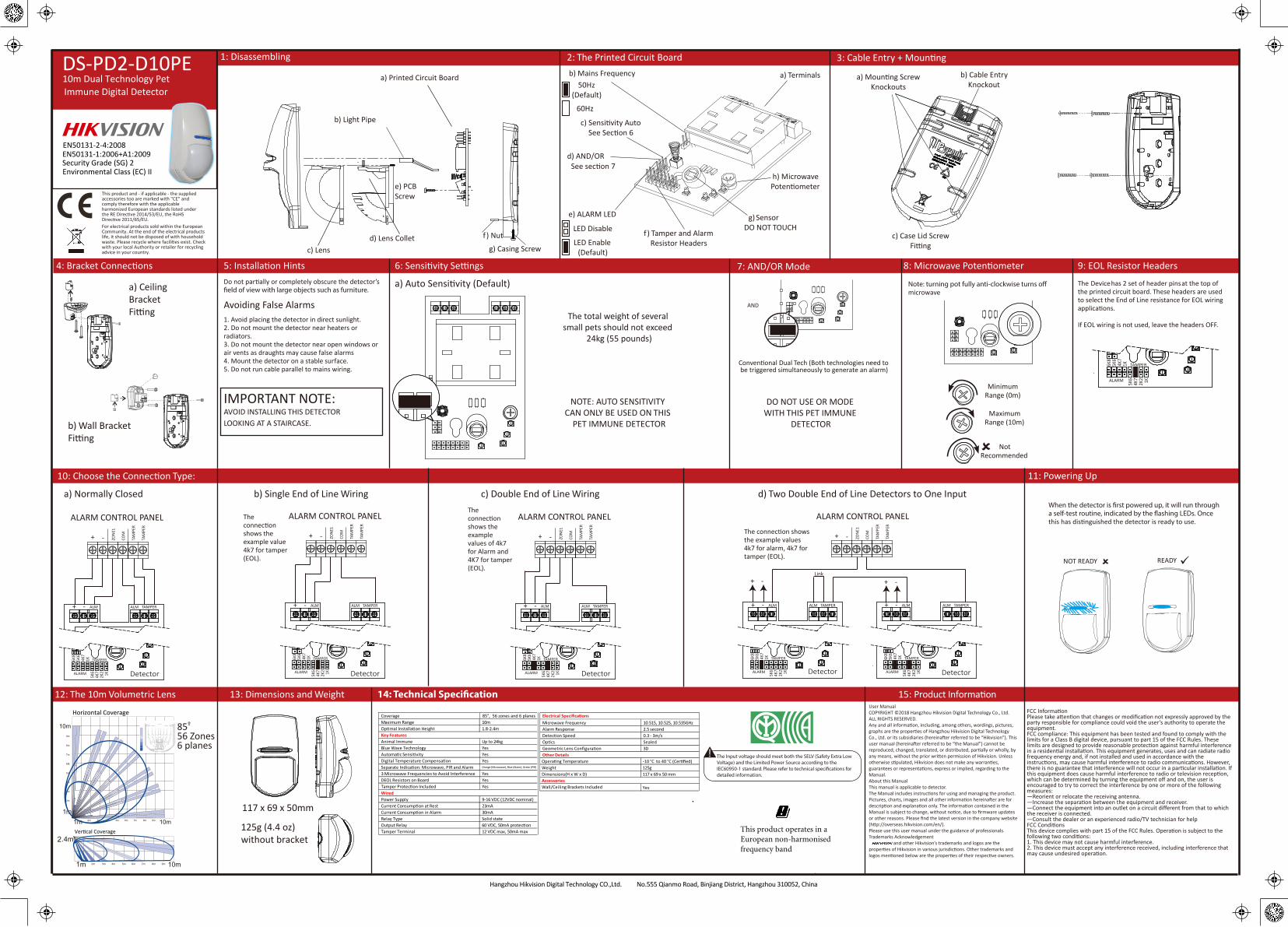
1: Disassembling
4: Bracket Connec 6: S ty S 7: AND/OR Mode 8: Microwave Poten ter5: Installa Hints 9: EOL Resistor Headers
a) Auto S ty (Default)
b) Wall BracketF
a) CeilingBracket F
ALARM CONTROL PANEL
+ - ZON
E1
COM
TAM
PER
TAM
PER
ALARM CONTROL PANEL
+ - ZON
E1
COM
TAM
PER
TAM
PER
ALARM CONTROL PANEL
+ - ZON
E1
COM
TAM
PER
TAM
PER
KXKX
+ -
5K6
5K6
6K8
4K7
4K7
2K2 1K
1K
ALARM
TAMPER
TAMPERALM ALM + -
5K6
5K6
6K8
4K7
4K7
2K2 1K
1K
ALARM
TAMPER
TAMPERALM ALM + -
5K6
5K6
6K8
4K7
4K7
2K2 1K
1K
ALARM
TAMPER
TAMPERALM ALM
ALARM CONTROL PANEL
+ - ZON
E1
COM
TAM
PER
TAM
PER
+ -Link
+ -
+ -
5K6
6K8
4K7
1K
TAMPERALM ALM + -
5K6
6K8
4K7
1K
TAMPERALM ALM
ALARM CONTROL PANEL
+ - ZON
E1
COM
TAM
PER
TAM
PER
+ -Link
+ -
+ -
5K6
6K8
4K7
1K
TAMPERALM ALM + -
5K6
6K8
4K7
1K
TAMPERALM ALM
2K2
Hard WiredResistor
a) Normally Closed
ALARM CONTROL PANEL
+ - ZON
E1
COM
TAM
PER
TAM
PER
ALARM CONTROL PANEL
+ - ZON
E1
COM
TAM
PER
TAM
PER
ALARM CONTROL PANEL
+ - ZON
E1
COM
TAM
PER
TAM
PER
KXKX
+ -
5K6
5K6
6K8
4K7
4K7
2K2 1K
1K
ALARM
TAMPER
TAMPERALM ALM + -
5K6
5K6
6K8
4K7
4K7
2K2 1K
1K
ALARM
TAMPER
TAMPERALM ALM + -
5K6
5K6
6K8
4K7
4K7
2K2 1K
1K
ALARM
TAMPER
TAMPERALM ALM
ALARM CONTROL PANEL
+ - ZON
E1
COM
TAM
PER
TAM
PER
+ -Link
-
+ -
5K6
6K8
4K7
1K TAMPER
TAMPERALM ALM -
4K7
1K TAMPER
TAMPERALM ALM
ALARM CONTROL PANEL
+ - ZON
E1
COM
TAM
PER
TAM
PER
+ -Link
+ -
+ -
5K6
6K8
4K7
1K TAMPER
TAMPERALM ALM + -
5K6
6K8
4K7
1K TAMPER
TAMPERALM ALM
2K2
Hard WiredResistor
b) Single End of Line Wiring
ALARM CONTROL PANEL
+ - ZON
E1
COM
TAM
PER
TAM
PER
ALARM CONTROL PANEL
+ - ZON
E1
COM
TAM
PER
TAM
PER
ALARM CONTROL PANEL
+ - ZON
E1
COM
TAM
PER
TAM
PER
KXKXKX
+ -
5K6
5K6
6K8
4K7
4K7
2K2 1K
1K
ALARM
TAMPER
TAMPERALM ALM + -
5K6
5K6
6K8
4K7
4K7
2K2 1K
1K
ALARM
TAMPER
TAMPERALM ALM + -
5K6
5K6
6K8
4K7
4K7
2K2 1K
1K
ALARM
TAMPER
TAMPERALM ALM
ALARM CONTROL PANEL
+ - ZON
E1
COM
TAM
PER
TAM
PER
+ -Link
+ -
KX
+ -
5K6
5K6
6K8
4K7
4K7
2K2 1K
1K
ALARM
TAMPER
TAMPERALM ALM
KX
+ -
5K6
5K6
6K8
4K7
4K7
2K2 1K
1K
ALARM
TAMPER
TAMPERALM ALM
ALARM CONTROL PANEL
+ - ZON
E1
COM
TAM
PER
TAM
PER
+ -Link
+ -
+ -
5K6
5K6
6K8
4K7
4K7
2K2 1K
1K
ALARM
TAMPER
TAMPERALM ALM + -
5K6
5K6
6K8
4K7
4K7
2K2 1K
1K
ALARM
TAMPER
TAMPERALM ALM
2K2
Hard WiredResistor
KX
+ -
5K6
5K6
6K8
4K7
4K7
2K2 1K
1K
ALARM
TAMPER
TAMPERALM ALM + -
5K6
5K6
6K8
4K7
4K7
2K2 1K
1K
ALARM
TAMPER
ALM
ALARM CONTROL PANEL
+ - ZON
E1
COM
TAM
PER
TAM
PER
+ -Link
+ -
+ -
5K6
5K6
6K8
4K7
4K7
2K2 1K
1K
ALARM
TAMPER
TAMPERALM ALM
KX
+ -
5K6
5K6
6K8
4K7
4K7
2K2 1K
1K
ALARM
TAMPER
TAMPERALM ALM
2K2
Hard WiredResistor
ALARM CONTROL PANEL
+ - ZON
E1
COM
TAM
PER
TAM
PER
ALARM CONTROL PANEL
+ - ZON
E1
COM
TAM
PER
TAM
PER
ALARM CONTROL PANEL
+ - ZON
E1
COM
TAM
PER
TAM
PER
KXKX
+ -
5K6
5K6
6K8
4K7
4K7
2K2 1K
1K
ALARM
TAMPER
TAMPERALM ALM + -
5K6
5K6
6K8
4K7
4K7
2K2 1K
1K
ALARM
TAMPER
TAMPERALM ALM + -
5K6
5K6
6K8
4K7
4K7
2K2 1K
1K
ALARM
TAMPER
TAMPERALM ALM
ALARM CONTROL PANEL
+ - ZON
E1
COM
TAM
PER
TAM
PER
+ -Link
+ -
5K6
6K8
4K7
1K TAMPER
TAMPERALM ALM
1K TAMPER
TAMPERALM ALM
ALARM CONTROL PANEL
+ - ZON
E1
COM
TAM
PER
TAM
PER
+ -Link
+ -
+ -
5K6
6K8
4K7
1K TAMPER
TAMPERALM ALM + -
5K6
6K8
4K7
1K TAMPER
TAMPERALM ALM
2K2
Hard WiredResistor
c) Double End of Line Wiring d) Two Double End of Line Detectors to One Input
15:
2: The Printed Circuit Board 3: Cable Entry + Moun
10: Choose the Connec Type:
12: The 10m Volumetric Lens 13: Dimensions and Weight
b) Light Pipe
a) Printed Circuit Board
d) Lens Colletc) Lens
e) PCB Screw
f) Nut
g) Casing Screw
h) MicrowavePoten ter
f ) Tamper and Alarm Resistor Headers
a) Terminals a) Moun Screw Knockouts
b) Cable Entry Knockout
c) Case Lid Screw F
b) Mains Frequency
c) S ty AutoSee Sec
d) AND/OR
e) ALARM LED
See sec
50Hz (Default)
LED Disable
60Hz
LED Enable(Default)
g) SensorDO NOT TOUCH
The Device has 2 set of header pins at the top of the printed circuit board. These headers are used to select the End of Line resistance for EOL wiring applica s.
If EOL wiring is not used, leave the headers OFF.
microwave
Conven Dual Tech (Both technologies need to be triggered simultaneously to generate an alarm)
AND
DO NOT USE OR MODE WITH THIS PET IMMUNE
DETECTOR
The connec ows the example values 4k7 for alarm, 4k7 for tamper (EOL).
The connecshows the example value 4k7 for tamper (EOL).
The connecshows the example values of 4k7 for Alarm and 4K7 for tamper (EOL).
Colour : White
LED Colours: Orange (Microwave), Blue (Alarm), Green (PIR)
Casing : 3mm ABS, 0.4mm HDPE in Lens Area
Detec Method : Low noise dual element pyroelectric sensor and Microwave Doppler Sensor
PIR S ty : AutoMax Pet Tolerance: 24kg (55 pounds)
Temperature Comp : Digital
Detec Range : 10m
Detec peed : 0.3 - 3.0m/s
Opera Voltage : 9-16V DC 13.8V DC typical
12V (Max)
Relay Output VDC, 42 VAC (RMS)
Contact Resistance : <10ohms
Mou Height : 2 - 2.4m
Tamper Switch : 12V 50mA
Storage Temp : -40°C to 80°C
-10°C to 40°C
Nominal working temperature: -30°C to 70°C
C AB L E E NT R YK NO C K O UT
The KX15DD Casing
KX15DDKX15DD
Control PanelControl Panel Control Panel
KX15DD
Control Panel
KX15DD
Control Panel
KX15DD
Wall Brack
Ceiling Brack
Normally Closed W iring
Zone Doubling Example (Matrix 424,832 or 832+) Two DEOL Detectors T o One Input
Single End of Line W iring (SEOL) Double End of Line W iring (DEOL) Remote LED Enable
O F F O N (Default)
S E NS IT IVIT Y S E T T ING S :
Auto, High or L ow.
S ee the diagams below
5K64K72K21K
+ – ALARM TAMPER LED
Alarm LED
Pyro Sensor
EOL Resist anceHeaders
EOL Resistor HeadersThe KX15DD Printed Circuit Board
The W or The KX15DD (Examples using 4k7 for alarm, 4k7 for tamper)
The KX15DD has two set s of header pins on the PCB, one oneither side of the connector blocks. These headers are used to select the End Of Line resistance for EOLIf EOL wiring is not used, leave the headers OFF .
The set to the le of the + terminal select s the value of the resist ance across the ALARM relay . The set to the right of theTAMPER terminals select s the value of the End Of Line resistor .
If the resist ance value you requireis not select able, leave theheaders off and wire a resistor of the required value between theappropriate terminals as shown.
The KX15DD has a terminal marked ‘LED’ which can be usedto enable the LED in walk test only on a alarm control panel.
This is used when the LED is disabled via the LED ON/OFF link.
To enable this feature, the LED terminal needs to be connectedto an Output at the alarm control p anel. When the system isis in walk test mode the Output should be at 0V .
The Output would be usually programmed as “Remote LEDenable”.
of the PCB
AUT O,HIGH or LOW .
Tplease see the diagrams below .
This symbol illustrates where the resistors are connected internally
6K85K64K72k21K
LOW AUTO AUTO HI
6K85K64K72k21K
5K64K72K21K
+ – ALARM TAMPER LED
LOWAUTO AUTOHI
LOWAUTO AUTOHI
+ – ALARM TAMPER LEDControl PanelOutput(0v in Walk Test)
6K85K64K72k21K
5K64K72K21K
+ – ALARM TAMPER LED
LOWAUTO AUTOHI
LOWAUTO AUTOHI
T T+AUX - Z 1 CO
M
5K64K72K21K
5K64K72K21K
+ – ALARM TAMPER LED6K85K64K72K2
1K
T T+AUX - Z 1 CO
M
5K64K72K21K
5K64K72K21K
+ – ALARM TAMPER LED6K85K64K72K2
1K
6K85K64K72K2
1K
T T+AUX - Z 1 CO
M
5K64K72K21K
5K64K72K21K
+ – ALARM TAMPER LED6K85K64K72K2
1K
6K85K64K72K2
1K
+AUX -
T T+AUX - Z 1 CO
M
5K64K72K21K
5K64K72K21K
+ – ALARM TAMPER LED6K85K64K72K2
1K
6K85K64K72K2
1K
6K85K64K72K2
1K6K85K64K72K2
1K
+AUX -
L ink
5K64K72K21K
5K64K72K21K
+ – ALARM TAMPER LED
+AUX -+AUX -
T T+AUX - Z 1 CO
M
L ink
5K64K72K21K
5K64K72K21K
5K64K72K21K
5K64K72K21K
+ – ALARM TAMPER LED + – ALARM TAMPER LED6K85K64K72K2
1K
6K85K64K72K2
1K
6K85K64K72K2
1K
6K85K64K72K2
1K
6K85K64K72k21K
5K64K72K21K
+ – ALAR M TAMPER LE D
LOWAUTO AUTO HI
LOWAUTO AUTOHI
This is the default
R INS 1038-3
®
®
®®
®
®
D E
C2 C3
E2 E3
E5
C5
®®
® ®®
Minimum Range (0m)
MaximumRange (10m)
Not Recommended
The total weight of several small pets should not exceed
24kg (55 pounds)
NOTE: AUTO SENSITIVITY CAN ONLY BE USED ON THIS
PET IMMUNE DETECTOR
Avoiding False Alarms1. Avoid placing the detector in direct sunlight.2. Do not mount the detector near heaters or radiators.3. Do not mount the detector near open windows or air vents as draughts may cause false alarms4. Mount the detector on a stable surface.5. Do not run cable parallel to mains wiring.
IMPORTANT NOTE:AVOID INSTALLING THIS DETECTOR LOOKING AT A STAIRCASE.
Do not par completely obscure the detector’s
tector is ready to use.
NOT READY READY
11: Powering Up
®
85º
56 Zones6 planes
Horizontal Coverage
Detector Detector DetectorDetectorDetector
Coverage 85°, 56 zones and 6 planesMaximum Range 10mOp mal Installa on Height 1.8-2.4m
Animal Immune Up to 24kgBlue Wave Technology YesAutoma c Sensi vity YesDigital Temperature Compensa on YesSeparate Indica on: Microwave, PIR and Alarm3 Microwave Frequencies to Avoid Interference YesDEOL Resistors on Board YesTamper Protec on Included Yes
Power Supply 9-16 VDC (12VDC nominal)Current Consump on at Rest 23mACurrent Consump on in Alarm 30mARelay Type Solid stateOutput Relay 60 VDC, 50mA protec onTamper Terminal 12 VDC max, 50mA max
Wired
Key Features
Microwave Frequency 10.515, 10.525, 10.535GHzAlarm Response 2.5 secondDetec on Speed 0.3 - 3m/sOp cs SealedGeometric Lens Configura on 3D
Opera ng Temperature -10 °C to 40 ° Weight 125g Dimensions(H x W x D) 117 x 69 x 50 mm
Wall/Ceiling Brackets Included Yes
Electrical Specifica ons
Other Details
Accessories
party responsible for compliance could void the user’s authority to operate the equipment.FCC compliance: This equipment has been tested and found to comply with the limits for a Class B digital device, pursuant to part 15 of the FCC Rules. These
frequency energy and, if not installed and used in accordance with the
which can be determined by turning the equipment off and on, the user is encouraged to try to correct the interference by one or more of the following measures:—Reorient or relocate the receiving antenna.
—Connect the equipment into an outlet on a circuit different from that to which the receiver is connected.—Consult the dealer or an experienced radio/TV technician for help
1. This device may not cause harmful interference.2. This device must accept any interference received, including interference that
User ManualCOPYRIGHT ©2018 Hangzhou Hikvision Digital Technology Co., Ltd. ALL RIGHTS RESERVED.
Manual.About this Manual This manual is applicable to detector.
or other reasons. Please find the latest version in the company website
Please use this user manual under the guidance of professionals.Trademarks Acknowledgement
and other Hikvision’s trademarks and logos are the
The Input voltage should meet both the SELV (Safety Extra Low Voltage) and the Limited Power Source according to the IEC60950-1 standard. Please refer to technical speci�cations for detailed information.
!
117 x 69 x 50mm
125g (4.4 oz) without bracket
EN50131-2-4:2008EN50131-1:2006+A1:2009Security Grade (SG) 2Environmental Class (EC) II
This product operates in aEuropean non-harmonisedfrequency band
Hangzhou Hikvision Digital Technology CO.,Ltd. No.555 Qianmo Road, Binjiang District, Hangzhou 310052, China
Orange (Microwave), Blue (Alarm), Green (PIR)
For electrical products sold within the European Community. At the end of the electrical products life, it should not be disposed of with household
with your local Authority or retailer for recycling advice in your country.
This product and - if applicable - the supplied accessories too are marked with "CE" and comply therefore with the applicable harmonized European standards listed under
U.
Hangzhou Hikvision Digital Technology CO.,Ltd. No.555 Qianmo Road, Binjiang District, Hangzhou 310052, China
F R A N Ç A I S1. Démontage. a) Circuit imprimé. b) Conducteur de lumière. c) Lentille. d) Douille de la lentille. e) Vis du
circuit imprimé. f) Écrou. g) Vis du boîtier.2. Le circuit imprimé. a) Bornes. b) Fréquence secteur. c) Sensibilité automatique. d) ET/OU. e) LED D'ALARME.
f) Connexions anti-sabotage et alarme/résistance. g) Capteur. h) Potentiomètre à micro-ondes.3. Fixation+entrée de câble. a) Découpes pour vis de montage. b) Découpe pour passage de câbles.
c) Raccord de la vis du couvercle du boîtier.4. Raccords du support. a) Raccord du support de montage au plafond. b) Raccord de support de montage
mural.5. Conseils d'installation
Éviter les fausses alertes1. Évitez d'exposer le détecteur à la lumière directe du soleil.2. N'installez pas le détecteur à proximité d'éléments chau�ants ou de radiateurs.3. N'installez pas le détecteur à proximité d'une fenêtre ouverte ou d'une grille d'aération, car les courants
d'air peuvent déclencher de fausses alarmes.4. Installez le détecteur sur une surface stable.5. Ne faites pas passer le câble parallèlement au câblage d'alimentation secteur.
6. Paramètres de sensibilité. Sensibilité automatique (par défaut)7. Mode ET/OU. Double technologie conventionnelle (les deux technologies doivent être déclenchées
simultanément pour générer une alarme)8. Potentiomètre Micro-ondes : Remarque : tourner le potentiomètre entièrement dans le sens anti-horaire
désactive les micro-ondes. Portée minimale (0 m). Portée maximale (10 m). Déconseillé9. Embases de résistance EOL. L'appareil présente 2 séries de broches de connexion en haut du circuit
imprimé. Ces embases sont utilisées pour choisir la résistance en extrémité de ligne des applications de câblage EOL. Si vous n'utilisez pas de câblage EOL, laissez les embases désactivées.
10. Sélectionnez le type de connexion. a) Normalement fermé. b) Câblage à extrémité de ligne unique. c) Câblage à double extrémité de ligne. d) Deux détecteurs à double extrémité de ligne pour une entrée.
11. Mise en route. Lorsque le détecteur est mis sous tension pour la première fois, il exécute une routine de test automatique indiquée par le clignotement des LED. Une fois la distinction faite, le détecteur est prêt à l'emploi.
12. Objectif volumétrique 10 m13. Dimensions et poids14. Spéci�cations techniquesZone de couverture : 85°, 56 zones et 6 plans. Portée maximale : 10 m. Installation optimale en hauteur : 1,8-2,4 mCaractéristiques principalesImmunité aux animaux : Jusqu’à 24 kg. Technologie Blue Wave. Sensibilité automatique. Compensation numérique de la température. Indication séparée : Micro-ondes, PIR et alarme ; orange (micro-ondes), bleu (alarme), vert (PIR). 3 fréquences micro-ondes pour éviter les interférences. Résistances DEOL intégrées. Protection anti-sabotage incluseFilaireSource d’alimentation : 9 à 16 V CC (12 V CC nominale). Consommation de courant au repos : 23 mA. Consommation de courant en alarme : 30 mA. Type de relais : À semiconducteurs. Sorties relais : Protection 60 V CC, 50 mA. Terminal anti-sabotage : 12 V CC max, 50 mA maxSpéci�cations électriquesFréquence des micro-ondes : 10,515, 10,525, 10,535 GHz. Activation de l’alarme : 2,5 secondes. Vitesse de détection : 0,3 à 3 m/s. Optiques : Scellées. Con�guration géométrique de la lentille : 3DAutres détailsTempérature de fonctionnement : -10 °C à 40 °C (certi�ée). Poids : 125 g. Dimensions (H x l x P) : 117 x 69 x 50 mmAccessoiresSupports de montage mural/au plafond inclus
La tension d’entrée doit respecter la très basse tension de sécurité (TBTS) et la source d’alimentation limitée conformément à la norme IEC60950-1. Veuillez vous référer aux caractéristiques techniques pour des informations détaillées.
P O R T U G U Ê S1. Desmontagem. a) Placa de circuito impresso (PCB). b) Tubo de luz. c) Lente. d) Encaixe da lente. e) Parafuso
da PCB. f) Porca. g) Parafuso do invólucro.2. Placa de circuito impresso (PCB). a) Terminais. b) Frequência da rede. c) Sensibilidade automática. d) E/OU.
e) LED de ALARME. F) Cabeçotes do resistor de alarme/violação. g) Sensor. h) Potenciômetro do micro-ondas.
3. Entrada de cabos + Montagem. a) Abertura dos parafusos de montagem. b) Abertura de entrada de cabo. c) Encaixe do parafuso da tampa do invólucro.
4. Conexões do suporte. a) Encaixe do suporte de teto. b) Encaixe do suporte de parede.5. Dicas de instalação
Evitar alarmes falsos1. Evite colocar o detector na luz solar direta.2. Não monte o detector perto de aquecedores ou radiadores.3. Não monte o detector perto de janelas abertas ou de saídas de ar, pois correntes de ar podem causar
alarmes falsos.4. Monte o detector em uma superfície estável.5. Não coloque o cabo em paralelo à �ação da rede.
6. Con�gurações de sensibilidade. Sensibilidade automática (padrão)7. Modo E/OU. Tecnologia dupla convencional (ambas as tecnologias precisam ser acionadas simultanea-
mente para gerar um alarme)8. Potenciômetro do micro-ondas: Observação: girar a bandeja totalmente no sentido anti-horário desliga o
micro-ondas. Alcance mínimo (0 m). Alcance máximo (10 m). Não recomendado9. Cabeçotes do resistor de EOL (�m de linha). O dispositivo tem dois conjuntos de pinos de cabeçotes na
parte superior da placa de circuito impresso. Esses cabeçotes são usados para selecionar a resistência de �m de linha para aplicações de �ação EOL. Se a �ação EOL (�m de linha) não for usada, deixe os cabeçotes DESLIGADOS.
10. Escolha o tipo de conexão. a) Normalmente fechada. b) Fiação de �m de linha simples (EOL). c) Fiação de �m de linha dupla (DEOL). d) Dois detectores de �m de linha dupla (DEOL) para uma entrada
11. Ligar. Quando o detector for ligado pela primeira vez ele passará por uma rotina de autoteste, indicada pelos LEDs piscando. Depois que isso acontecer, o detector estará pronto para uso.
12. Lente volumétrica de 10 m13. Dimensões e peso14. Especi�cação técnicaCobertura: 85°, 56 zonas e 6 planos. Alcance máximo: 10 m Altura ideal de instalação: 1,8 a 2,4 mRecursos principaisImunidade a animais: até 24 kg. Tecnologia Blue Wave. Sensibilidade automática. Compensação de temperatura digital. Indicação separada: Micro-ondas, PIR e alarme; laranja (micro-ondas), azul (alarme) e verde (PIR). Três frequências de micro-ondas para evitar interferências. Resistores de DEOL integrados. Proteção antiviolação incluídaCom �oFonte de alimentação: 9 a 16 VCC (12 VCC nominal). Consumo de corrente em repouso: 23 mA. Consumo de corrente em alarme: 30 mA. Tipo de relé: estado sólido. Relé de saída: 60 VCC, proteção de 50 mA. Terminal antiviolação: máx. de 12 VDC e 50 mAóptica selada de visão duplaFrequências de micro-ondas: 10,515, 10,525 e 10,535 GHz. Resposta do alarme: 2,5 segundos. Velocidade de detecção: 0,3 a 3 m/s. Óptica: selado. Con�guração de lente geométrica: 3DOutros detalhesTemperatura de operação: -10 °C a 40 °C (certi�cado). Peso: 125 g. Dimensões (A x L x P): 117 x 69 x 50 mmAcessóriosSuportes de parede e teto incluídos
A tensão de entrada deve atender tanto a SELV (Extra Baixa Tensão - EBT - de Segurança) quanto a Fonte de Tensão Limitada (Limited Power Source), de acordo com a norma IEC60950-1. Para obter mais informações, consulte as especi�cações técnicas.
Р У С С К И Й1. Демонтаж. а) Печатная плата. б) Трубка подсветки. в) Объектив. г) Оправа объектива. д) Винт печатной
платы. е) Гайка ж) Винт корпуса.2. Печатная плата. а) Клеммы. б) Частота сети. в) Автоматическая настройка чувствительности. г) Функции
И/ИЛИ. д) Светодиод ТРЕВОГИ. е) Датчики взлома и сигнализации/резистивные датчики ж) Датчик. з) Потенциометр микроволнового датчика.
3. Кабельные вводы+монтаж. а) Отверстия для крепежных винтов. б) Отверстия для ввода кабелей.в) Крепление для винта крышки корпуса.
4. Подключения кронштейна. а) Крепление для потолочного кронштейна. б) Крепление для настенного кронштейна.
5. Советы по установкеКак избежать ложных сигналов тревоги1. Не устанавливайте детектор под прямыми солнечными лучами.2. Не устанавливайте детектор рядом с нагревательными приборами и радиаторами.3. Не устанавливайте детектор рядом с открытыми окнами или вентиляционными отверстиями, так как
сквозняки могут вызвать ложные сигналы тревоги.4. Устанавливайте детектор только на устойчивой поверхности.5. Не прокладывайте кабель параллельно проводам питающей сети.
6. Параметры чувствительности. Автоматическая чувствительность (по умолчанию)7. Режим И/ИЛИ. Стандартная двойная технология (для генерации сигнала тревоги обе системы должны
быть сработать одновременно)8. Микроволновый потенциометр: Примечание. При повороте ручки против часовой стрелки до упора
микроволновый датчик выключается. Минимальная дальность (0 м) Максимальная дальность (10 м). Не рекомендуется
9. Головки концевых резисторов. Устройство имеет 2 набора штыревых перемычек в верхней части печатной платы. Эти головки используются для выбора концевого сопротивления для концевой проводки. Если концевая проводка не используется, оставьте эти головки отключенными.
10. Выбор типа подключения. а) Нормально замкнуто. б) Один конец линии. в) Два конца линии. г) Два двойных конца детекторов линии на один вход
11. Включение питания. При первом включении питания детектор выполняет процедуру самотестирования, на что указывают мигающие индикаторы. Когда индикаторы погаснут, детектор будет готов к работе.
12. Объемный объектив, 10 м13. Размеры и масса14. Технические характеристикиОбзор: 85°, 56 зон и 6 плоскостей. Максимальная дальность: 10 м. Оптимальная высота установки: 1,8–2,4 мОсновные функцииОтсутствие ложных срабатываний при обнаружении домашних животных: до 24 кг Технология Blue Wave. Автоматическая чувствительность. Цифровая компенсация температуры. Отдельные светодиоды: микроволновый датчик, пассивный ИК-датчик 1, сигнал тревоги: оранжевый (микроволновой датчик), синий (сигнал тревоги), зеленый (пассивный ИК-датчик). 3 частоты микроволнового излучения для предотвращения помех. Резисторы DEOL на плате. Защита от взлома включенаПроводнойЭлектропитание: 9–16 В пост. тока (номинальное значение: 12 В пост. тока). Потребление тока в состоянии покоя: 23 мА Потребление тока при срабатывании сигнализации: 30 мА Тип реле: Полупроводниковое. Выход реле: 60 В пост. тока, защита при 50 мА. Клеммы защиты от взлома: Макс. 12 В пост. тока, макс. 50 мАЭлектрические характеристикиЧастота микроволнового излучения: 10,515; 10,525; 10,535 ГГц. Время срабатывания сигнализации: 2,5 с. Скорость обнаружения: 0,3–3 м/с. Оптика: Герметичная. Геометрическая конфигурация объектива: 3DДругие данныеРабочая температура: От -10 °C до 40 °C (сертифицировано). Масса: 125 г. Размеры (В x Ш x Г): 117 x 69 x 50 ммВспомогательное оборудованиеКронштейны для монтажа на стене/потолке прилагаются
Электропитание должно соответствовать требованиям стандарта IEC60950-1 для безопасного сверхнизкого напряжения (SELV) и ограниченного напряжения питания. Подробная информация приведена в таблице технических данных.
E S P A Ñ O L
1. Desmontaje. a) Circuito impreso. b) Tubo de luz. c) Lente. d) Pinza de lente. e) Tornillo de circuito impreso. f) Tuerca. g) Tornillo de la carcasa.
2. Circuito impreso. a) Terminales. b) Frecuencia eléctrica. c) Sensibilidad automática. d) Y/O. e) LED DE ALARMA. f) Cabezales de resistencia/manipulación y alarma. g) Sensor. h) Potenciómetro de microondas.
3. Entrada de los cables+montaje. a) Troquel para tornillo de montaje. b) Troquel para entrada de cable. c) Conector de tornillo de tapa de carcasa.
4. Conexiones de soportes. a) Conector de soporte para techo. b) Conector de soporte para pared.5. Consejos de instalación
Cómo evitar falsas alarmas1. Evite que al detector le dé la luz del sol directamente.2. No coloque el detector cerca de calentadores o radiadores.3. No monte el detector cerca de ventanas abiertas ni conductos de aire ya que las corrientes de aire pueden
provocar falsas alarmas.4. Coloque el detector sobre una super�cie estable.5. No extienda el cable en paralelo al cableado eléctrico.
6. Ajustes de sensibilidad. Sensibilidad automática (predeterminada)7. Modo AND/OR (Y/O). Tecnología dual convencional (ambas tecnologías deben activarse simultáneamente
para generar una alarma).8. Potenciómetro de microondas: Nota: el sistema de microondas se apaga al girar la rueda totalmente en
sentido contrario a las agujas del reloj. Alcance mínimo (0 m). Alcance máximo (10 m). No recomendado9. Cabezales de resistencia de �n de línea (EOL, por sus siglas en inglés). El dispositivo tiene 2 juegos de
clavijas de cabezal en la parte superior del circuito impreso. Se utilizan para seleccionar la resistencia de �n de línea de las aplicaciones de cableado EOL. Si no usa un cableado de �n de línea, ponga los cabezales en modo OFF (DESACTIVADOS).
10. Elija el tipo de conexión. a) Normalmente cerrado. b) Extremo único del cableado de línea. c) Extremo doble del cableado de línea. d) Dos extremos dobles de detectores de línea a una entrada.
11. Encendido. La primera vez que se encienda el detector, realizará unas pruebas de autoveri�cación (se indicarán por medio de LED parpadeantes). Cuando se apaguen, el detector estará listo para usarse.
12. Lentes volumétricas a 10 m.13. Dimensiones y peso14. Especi�caciones técnicasAlcance: 85º, 56 zonas y 6 planos. Alcance máximo: 10 m Altura de instalación óptima: 1,8-2,4 mFunciones clavesInmunidad a mascotas: hasta 24 kg. Tecnología Blue Wave. Sensibilidad automática. Compensación de temperatura digital. Indicación separada: microondas, PIR y alarma; naranja (microondas), azul (alarma), verde (PIR). 3 frecuencias de microondas para evitar interferencias. Resistencia DEOL en circuito. Protección contra manipulaciones incluidaPor cableAlimentación eléctrica: 9-16 V CC (12 V CC nominal). Consumo de corriente en reposo: 23 mA Consumo de corriente en alarma: 30mA Tipo de relé: De estado sólido. Relé de salida: protección de 60 V CC, 50 mA. Terminal de seguridad: 12 V CC máx., 50 mA máx.Especi�caciones eléctricasFrecuencia de microondas: 10,515,10,525 y 10,535 GHz. Respuesta de alarma: 2,5 segundos. Velocidad de detección: 0,3 - 3 m/s. Óptica: Sellada Con�guración de lente geométrica: 3DOtra informaciónTemperatura de funcionamiento: -10 °C a 40 °C (certi�cado). Peso: 125 g Dimensiones (alto x ancho x profundidad): 117 x 69 x 50 mmAccesoriosSoportes de montaje en pared/techo incluidos.
La tensión de entrada debe cumplir las disposiciones SELV (muy baja tensión de seguridad) y de fuente de alimentación limitada de la norma IEC60950-1. Consulte las especi�caciones técnicas para obtener información detallada.
I T A L I A N O1. Smontaggio .a) Scheda a circuiti stampati. b) Illuminazione tubolare. c) Obiettivo. d) Chiusura obiettivo.
e) Vite PCB. f) Dado. g) Vite custodia.2. Scheda a circuiti stampati. a) Terminali. b) Frequenza alimentazione. c) Sensibilità automatica. d) AND/OR.
e) LED ALLARME. f) Jumper antimanomissione e di Allarmi/Resistenze. g) Sensore. h) Potenziometro a microonde.
3. Montaggio + accesso cavo. a) Fori semitranciati per viti di montaggio. b) Foro semitranciato ingresso cavo. c) Attacco vite coperchio custodia.
4. Collegamenti della sta�a. a) Attacco sta�a a so�tto. b) Attacco sta�a a parete.5. Consigli di installazione
Evitare i falsi allarmi1. Evitare di collocare il rilevatore alla luce solare diretta.2. Non montare il rilevatore vicino a radiatori o caloriferi.3. Non montare il rilevatore in prossimità di �nestre aperte o correnti d'aria poiché gli spi�eri possono
causare falsi allarmi.4. Montare il rilevatore su una super�cie stabile.5. Non far passare il cavo parallelamente al cablaggio di rete.
6. Impostazioni di sensibilità. Sensibilità automatica (prede�nito)7. Modalità AND/OR. Tecnologia doppia convenzionale (Entrambe le tecnologie devono essere attivate
simultaneamente per generare un allarme)8. Potenziometro microonde: Nota: per disattivare il sistema a microonde ruotare completamente il
potenziometro in senso antiorario. Portata minima (0 m). Portata massima (10 m). Sconsigliato9. Jumper resistenze EOL. Il dispositivo presenta due set di pin di jumper sulla parte superiore della scheda a
circuiti stampati. Questi jumper vengono utilizzati per selezionare la resistenza di �ne linea per il cablaggio EOL. Se non si utilizza il cablaggio EOL, lasciare i jumper su OFF.
10. Scegliere il tipo di connessione. a) Normalmente chiuso. b) Cablaggio di �ne linea singolo. c) Cablaggio di �ne linea doppio. d) Due Rilevatori di �ne linea doppi per un ingresso
11. Accensione. Alla prima accensione, il rilevatore esegue una procedura di auto-test (indicata dai LED lampeggianti). Quando i LED si spengono, il rilevatore è pronto all'uso.
12. Ottica volumetrica da 10 m13. Dimensioni e peso14. Speci�che tecnicheCopertura: 85°, 56 zone e 6 piani. Portata massima: 10 m. Installazione ottimale in altezza: 1,8-2,4 mFunzioni principaliImmunità agli animali: �no a 24 kg. Tecnologia Blue Wave. Sensibilità automatica. Compensazione digitale della temperatura. Indicazioni distinte: Microonde, PIR e allarme; arancione (microonde), blu (allarme), verde (PIR). 3 frequenze a microonde per evitare interferenze. Resistenze DEOL sulla scheda. Protezione antimanomissioni inclusaCablatoAlimentazione: 9-16 V CC (12 V CC nominale). Assorbimento di corrente a riposo: 23 mA. Assorbimento di corrente in stato di allarme: 30 mA. Tipo di relè: a stato solido. Relè di uscita: 60 V CC, protezione 50 mA. Terminale antimanomissione: 12 V CC max, 50 mA maxSpeci�che elettricheFrequenza microonde: 10,515, 10,525, 10,535 GHz. Risposta agli allarmi: 2,5 secondi. Velocità di rilevamento: 0,3 - 3 m/s. Componenti ottici: Sigillati. Con�gurazione geometrica dell'obiettivo: 3DAltri dettagliTemperatura di esercizio: Da -10 °C a 40 °C (Certi�cata). Peso: 125 g. Dimensioni (A x L x P): 117 x 69 x 50 mmAccessoriSta�e di montaggio a parete/so�tto incluse
La tensione di ingresso deve rispettare sia i requisiti SELV (Tensione bassissima di sicurezza) che quelli per fonti di alimentazione limitate, previsti dallo standard IEC60950-1. Consultare le speci�che tecniche per le informazioni dettagliate.