DS-K2600 Series - us.hikvision.com · DS-K2600 Series Access Controller ii Legal Disclaimer TO THE...
142
DS-K2600 Series Access Controller User Manual UD.6L0206D1190A01
Transcript of DS-K2600 Series - us.hikvision.com · DS-K2600 Series Access Controller ii Legal Disclaimer TO THE...

DS-K2600 Series
Access Controller
User Manual
UD.6L0206D1190A01
DS-K2600 Series Access Controller
i
User Manual
COPYRIGHT © 2015 Hangzhou Hikvision Digital Technology Co., Ltd.
ALL RIGHTS RESERVED.
Any and all information, including, among others, wordings, pictures, graphs are the
properties of Hangzhou Hikvision Digital Technology Co., Ltd. or its subsidiaries
(hereinafter referred to be “Hikvision”). This user manual (hereinafter referred to
be “the Manual”) cannot be reproduced, changed, translated, or distributed,
partially or wholly, by any means, without the prior written permission of Hikvision.
Unless otherwise stipulated, Hikvision does not make any warranties, guarantees or
representations, express or implied, regarding to the Manual.
About this Manual
This Manual is applicable to Access Controller
Product Name Serials
Access Controller
DS-K2601 Serials Access Controller
DS-K2602 Serials Access Controller
DS-K2604 Serials Access Controller
The Manual includes instructions for using and managing the product. Pictures,
charts, images and all other information hereinafter are for description and
explanation only. The information contained in the Manual is subject to change,
without notice, due to firmware updates or other reasons. Please find the latest
version in the company website (http://overseas.hikvision.com/en/).
Please use this user manual under the guidance of professionals.
Trademarks Acknowledgement
and other Hikvision’s trademarks and logos are the properties of
Hikvision in various jurisdictions. Other trademarks and logos mentioned below are
the properties of their respective owners.
DS-K2600 Series Access Controller
ii
Legal Disclaimer
TO THE MAXIMUM EXTENT PERMITTED BY APPLICABLE LAW, THE PRODUCT
DESCRIBED, WITH ITS HARDWARE, SOFTWARE AND FIRMWARE, IS PROVIDED “AS
IS”, WITH ALL FAULTS AND ERRORS, AND HIKVISION MAKES NO WARRANTIES,
EXPRESS OR IMPLIED, INCLUDING WITHOUT LIMITATION, MERCHANTABILITY,
SATISFACTORY QUALITY, FITNESS FOR A PARTICULAR PURPOSE, AND
NON-INFRINGEMENT OF THIRD PARTY. IN NO EVENT WILL HIKVISION, ITS
DIRECTORS, OFFICERS, EMPLOYEES, OR AGENTS BE LIABLE TO YOU FOR ANY
SPECIAL, CONSEQUENTIAL, INCIDENTAL, OR INDIRECT DAMAGES, INCLUDING,
AMONG OTHERS, DAMAGES FOR LOSS OF BUSINESS PROFITS, BUSINESS
INTERRUPTION, OR LOSS OF DATA OR DOCUMENTATION, IN CONNECTION WITH
THE USE OF THIS PRODUCT, EVEN IF HIKVISION HAS BEEN ADVISED OF THE
POSSIBILITY OF SUCH DAMAGES.
REGARDING TO THE PRODUCT WITH INTERNET ACCESS, THE USE OF PRODUCT
SHALL BE WHOLLY AT YOUR OWN RISKS. HIKVISION SHALL NOT TAKE ANY
RESPONSIBILITES FOR ABNORMAL OPERATION, PRIVACY LEAKAGE OR OTHER
DAMAGES RESULTING FROM CYBER ATTACK, HACKER ATTACK, VIRUS INSPECTION,
OR OTHER INTERNET SECURITY RISKS; HOWEVER, HIKVISION WILL PROVIDE TIMELY
TECHNICAL SUPPORT IF REQUIRED.
SURVEILLANCE LAWS VARY BY JURISDICTION. PLEASE CHECK ALL RELEVANT LAWS
IN YOUR JURISDICTION BEFORE USING THIS PRODUCT IN ORDER TO ENSURE THAT
YOUR USE CONFORMS THE APPLICABLE LAW. HIKVISION SHALL NOT BE LIABLE IN
THE EVENT THAT THIS PRODUCT IS USED WITH ILLEGITIMATE PURPOSES.
IN THE EVENT OF ANY CONFLICTS BETWEEN THIS MANUAL AND THE APPLICABLE
LAW, THE LATER PREVAILS.
0101011060112
DS-K2600 Series Access Controller
iii
Regulatory Information
FCC Information
FCC compliance: This equipment has been tested and found to comply with the
limits for a digital device, pursuant to part 15 of the FCC Rules. These limits are
designed to provide reasonable protection against harmful interference when
the equipment is operated in a commercial environment. This equipment
generates, uses, and can radiate radio frequency energy and, if not installed and
used in accordance with the instruction manual, may cause harmful
interference to radio communications. Operation of this equipment in a
residential area is likely to cause harmful interference in which case the user
will be required to correct the interference at his own expense.
FCC Conditions
This device complies with part 15 of the FCC Rules. Operation is subject to the
following two conditions:
1. This device may not cause harmful interference.
2. This device must accept any interference received, including interference
that may cause undesired operation.
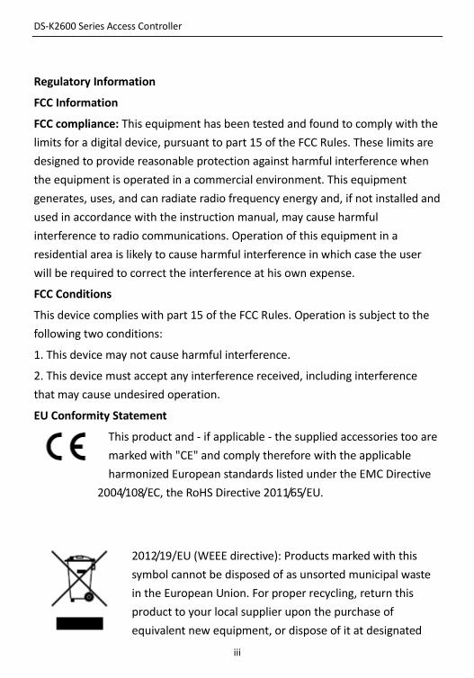
EU Conformity Statement
This product and - if applicable - the supplied accessories too are
marked with "CE" and comply therefore with the applicable
harmonized European standards listed under the EMC Directive
2004/108/EC, the RoHS Directive 2011/65/EU.
2012/19/EU (WEEE directive): Products marked with this
symbol cannot be disposed of as unsorted municipal waste
in the European Union. For proper recycling, return this
product to your local supplier upon the purchase of
equivalent new equipment, or dispose of it at designated
DS-K2600 Series Access Controller
iv
collection points. For more information see: www.recyclethis.info.
2006/66/EC (battery directive): This product contains a battery
that cannot be disposed of as unsorted municipal waste in the
European Union. See the product documentation for specific
battery information. The battery is marked with this symbol,
which may include lettering to indicate cadmium (Cd), lead (Pb), or mercury
(Hg). For proper recycling, return the battery to your supplier or to a designated
collection point. For more information see: www.recyclethis.info.
Industry Canada ICES-003 Compliance
This device meets the CAN ICES-3 (A)/NMB-3(A) standards requirements.
DS-K2600 Series Access Controller
v
Preventive and Cautionary Tips
Before connecting and operating your device, please be advised of the
following tips:
• Ensure unit is installed in a well-ventilated, dust-free environment.
• Keep all liquids away from the device.
• Ensure environmental conditions meet factory specifications.
• Ensure unit is properly secured to a rack or shelf. Major shocks or jolts to the unit as a
result of dropping it may cause damage to the sensitive electronics within the unit.
• Use the device in conjunction with an UPS if possible.
• Power down the unit before connecting and disconnecting accessories and peripherals.
• A factory recommended HDD should be used for this device.
• Improper use or replacement of the battery may result in hazard of explosion. Replace
with the same or equivalent type only. Dispose of used batteries according to the
instructions provided by the manufacturer.
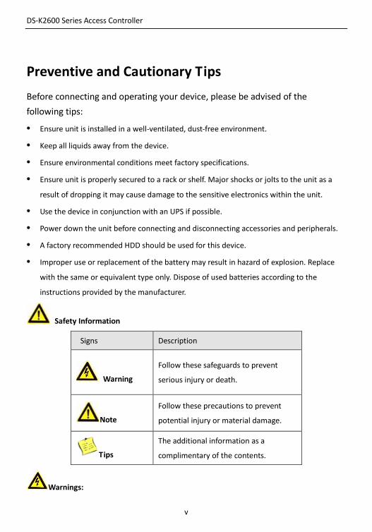
Safety Information
Signs Description
Warning
Follow these safeguards to prevent
serious injury or death.
Note
Follow these precautions to prevent
potential injury or material damage.
Tips
The additional information as a
complimentary of the contents.
Warnings:
DS-K2600 Series Access Controller
vi
Please adopt the power adapter from the legitimate factory which can meet the safety extra
low voltage (SELV) standard.
Do not install, wiring, or uninstall when the power is still on.
To reduce the risk of fire or electrical shock, do not expose this product to rain or moisture.
This installation should be made by a qualified service person and should conform to all the
local codes.
If the product does not work properly, please contact your dealer or the nearest service
center. Never attempt to disassemble the camera yourself. (We shall not assume any
responsibility for problems caused by unauthorized repair or maintenance.)
Note:
Please do not drop the objects on hard surface, and keep the equipment from the magnetic
field. Avoid install the equipment to the vibrated or vulnerable places.
Please do not install the device in the extreme temperature (higher than 65℃ or lower than
-20℃)
Keep ventilation.
Do not operate in humid environment.
Do not operate in explosive environment.
Keep the device clean and dry.
Avoid bare electrical wire.
DS-K2600 Series Access Controller
1
Table of Contents
1 Product Description ............................................................................................ 3
1.1 Overview .......................................................................................................................... 3
1.2 Main Feature ................................................................................................................... 3
2 Appearance ........................................................................................................ 5
2.1 Component Description ................................................................................................... 5
2.1.1 Access Controller Component Schematic Diagram ................................................... 5
3 Terminal Connection ........................................................................................... 7
3.1 Terminals Description ...................................................................................................... 7
3.1.1 DS-K2601Terminal Description .................................................................................. 7
3.1.2 DS-K2602Terminal Description ................................................................................ 11
3.1.3 DS-K2604 Terminal Description ............................................................................... 16
4 Card Reader Installation ................................................................................... 22
4.1 External Terminal ........................................................................................................... 22
4.1.1 DS-K2601 External Terminals .................................................................................. 22
4.1.2 DS-K2602 External Terminals .................................................................................. 22
4.1.3 DS-K2604 External Terminals .................................................................................. 22
4.2 Card Reader Installation ................................................................................................ 23
4.2.1 The Connection of Wiegand Card Reader ............................................................... 23
4.2.2 RS485 Card Reader Connection ............................................................................... 24
4.3 Installing E-Lock ............................................................................................................. 24
4.3.3 Installation of Cathode Lock .................................................................................... 24
4.3.4 Installation of Anode Lock ....................................................................................... 25
4.4 Connecting the External Alarm Device .......................................................................... 25
4.5 Door Button Wiring Diagram ......................................................................................... 26
4.6 The Connection of Magnetics Detection ....................................................................... 26
4.7 Connecting Power Supply .............................................................................................. 27
DS-K2600 Series Access Controller
2
4.8 Arming Region Input Terminal ....................................................................................... 27
4.8.5 Connecting Normally Open Detector ...................................................................... 27
4.8.6 Connecting Normally Closed Detector .................................................................... 28
4.9 Fire Alarm Module Wiring ............................................................................................. 28
5 Settings ............................................................................................................ 29
5.1 Initializing the Hardware................................................................................................ 29
5.2 Relay Input NO/NC ........................................................................................................ 29
5.2.1 Lock Relay Output ................................................................................................... 29
5.2.2 Alarm Relay Output Status ...................................................................................... 30
6 Activating the Control Panel ............................................................................. 32
6.1 Activation via SADP Software ........................................................................................ 32
6.2 Activation via Client Software ........................................................................................ 34
DS-K2600 Series Access Controller
3
1 Product Description
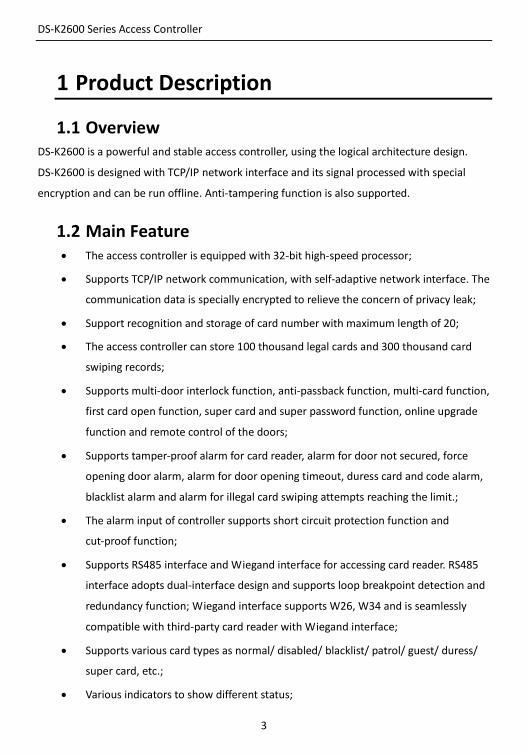
1.1 Overview DS-K2600 is a powerful and stable access controller, using the logical architecture design.
DS-K2600 is designed with TCP/IP network interface and its signal processed with special
encryption and can be run offline. Anti-tampering function is also supported.
1.2 Main Feature The access controller is equipped with 32-bit high-speed processor;
Supports TCP/IP network communication, with self-adaptive network interface. The
communication data is specially encrypted to relieve the concern of privacy leak;
Support recognition and storage of card number with maximum length of 20;
The access controller can store 100 thousand legal cards and 300 thousand card
swiping records;
Supports multi-door interlock function, anti-passback function, multi-card function,
first card open function, super card and super password function, online upgrade
function and remote control of the doors;
Supports tamper-proof alarm for card reader, alarm for door not secured, force
opening door alarm, alarm for door opening timeout, duress card and code alarm,
blacklist alarm and alarm for illegal card swiping attempts reaching the limit.;
The alarm input of controller supports short circuit protection function and
cut-proof function;
Supports RS485 interface and Wiegand interface for accessing card reader. RS485
interface adopts dual-interface design and supports loop breakpoint detection and
redundancy function; Wiegand interface supports W26, W34 and is seamlessly
compatible with third-party card reader with Wiegand interface;
Supports various card types as normal/ disabled/ blacklist/ patrol/ guest/ duress/
super card, etc.;
Various indicators to show different status;
DS-K2600 Series Access Controller
4
Supports time synchronization via NTP, manual or automatic method;
Supports record storage function when it is offline and insufficient storage space
storage alarm function;
The access controller has backup battery design, watchdog design and
tamper-proof function;
Data can be permanently saved after the access controller is powered off.
Supports I/O linkage, and event linkage;
Supports Ehome protocol, DNS domainn name analysis, and inter-network
communication.
500 groups of password under the authentication mode of card and password;
DS-K2600 Series Access Controller
5
2 Appearance
2.1 Component Description
2.1.1 Access Controller Component Schematic Diagram
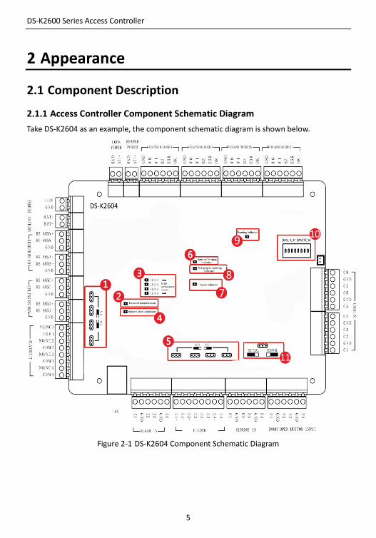
Take DS-K2604 as an example, the component schematic diagram is shown below.
Figure 2-1 DS-K2604 Component Schematic Diagram
DS-K2600 Series Access Controller
6
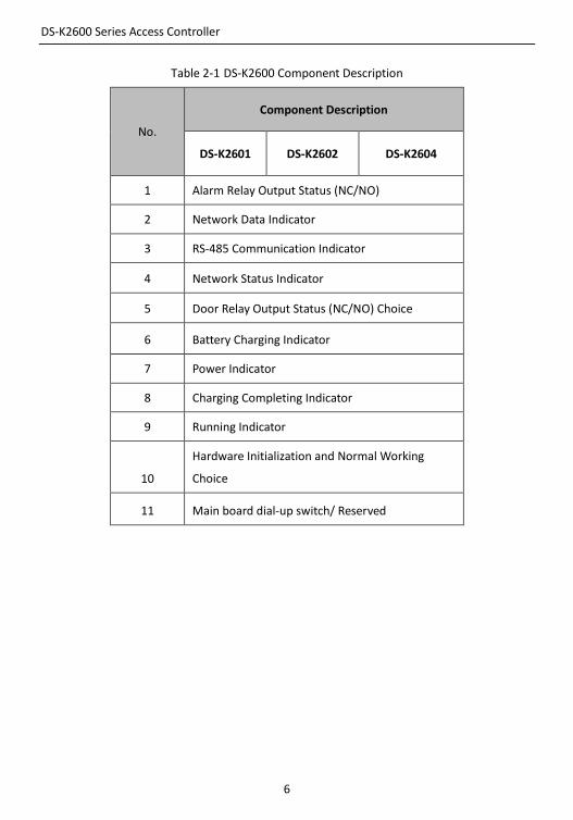
Table 2-1 DS-K2600 Component Description
No.
Component Description
DS-K2601 DS-K2602 DS-K2604
1 Alarm Relay Output Status (NC/NO)
2 Network Data Indicator
3 RS-485 Communication Indicator
4 Network Status Indicator
5 Door Relay Output Status (NC/NO) Choice
6 Battery Charging Indicator
7 Power Indicator
8 Charging Completing Indicator
9 Running Indicator
10
Hardware Initialization and Normal Working
Choice
11 Main board dial-up switch/ Reserved

DS-K2600 Series Access Controller
7
3 Terminal Connection
3.1 Terminals Description
3.1.1 DS-K2601Terminal Description
Figure 3-1 DS-K2601 Terminals
DS-K2600 Series Access Controller
8
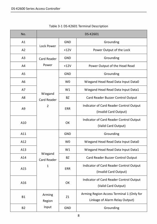
Table 3-1 DS-K2601 Terminal Description
No. DS-K2601
A1 Lock Power
GND Grounding
A2 +12V Power Output of the Lock
A3 Card Reader
Power
GND Grounding
A4 +12V Power Output of the Head Read
A5
Wiegand
Card Reader
2
GND Grounding
A6 W0 Wiegand Head Read Data Input Data0
A7 W1 Wiegand Head Read Data Input Data1
A8 BZ Card Reader Buzzer Control Output
A9 ERR Indicator of Card Reader Control Output
(Invalid Card Output)
A10 OK Indicator of Card Reader Control Output
(Valid Card Output)
A11
Wiegand
Card Reader
1
GND Grounding
A12 W0 Wiegand Head Read Data Input Data0
A13 W1 Wiegand Head Read Data Input Data1
A14 BZ Card Reader Buzzer Control Output
A15 ERR Indicator of Card Reader Control Output
(Invalid Card Output)
A16 OK Indicator of Card Reader Control Output
(Valid Card Output)
B1 Arming
Region
Input
Z1 Arming Region Access Terminal 1 (Only for
Linkage of Alarm Relay Output)
B2 GND Grounding
DS-K2600 Series Access Controller
9
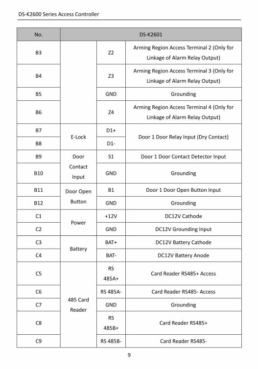
No. DS-K2601
B3 Z2 Arming Region Access Terminal 2 (Only for
Linkage of Alarm Relay Output)
B4 Z3 Arming Region Access Terminal 3 (Only for
Linkage of Alarm Relay Output)
B5 GND Grounding
B6 Z4 Arming Region Access Terminal 4 (Only for
Linkage of Alarm Relay Output)
B7 E-Lock
D1+ Door 1 Door Relay Input (Dry Contact)
B8 D1-
B9 Door
Contact
Input
S1 Door 1 Door Contact Detector Input
B10 GND Grounding
B11 Door Open
Button
B1 Door 1 Door Open Button Input
B12 GND Grounding
C1 Power
+12V DC12V Cathode
C2 GND DC12V Grounding Input
C3 Battery
BAT+ DC12V Battery Cathode
C4 BAT- DC12V Battery Anode
C5
485 Card
Reader
RS
485A+ Card Reader RS485+ Access
C6 RS 485A- Card Reader RS485- Access
C7 GND Grounding
C8 RS
485B+ Card Reader RS485+
C9 RS 485B- Card Reader RS485-
DS-K2600 Series Access Controller
10
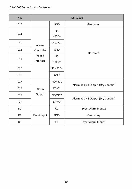
No. DS-K2601
C10 GND Grounding
C11
Access
Controller
RS485
Interface
RS
485C+
Reserved
C12 RS 485C-
C13 GND
C14 RS
485D+
C15 RS 485D-
C16 GND
C17
Alarm
Output
NO/NC1 Alarm Relay 1 Output (Dry Contact)
C18 COM1
C19 NO/NC2 Alarm Relay 2 Output (Dry Contact)
C20 COM2
D1
Event Input
C2 Event Alarm Input 2
D2 GND Grounding
D3 C1 Event Alarm Input 1
DS-K2600 Series Access Controller
11
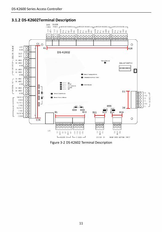
3.1.2 DS-K2602Terminal Description
Figure 3-2 DS-K2602 Terminal Description
DS-K2600 Series Access Controller
12
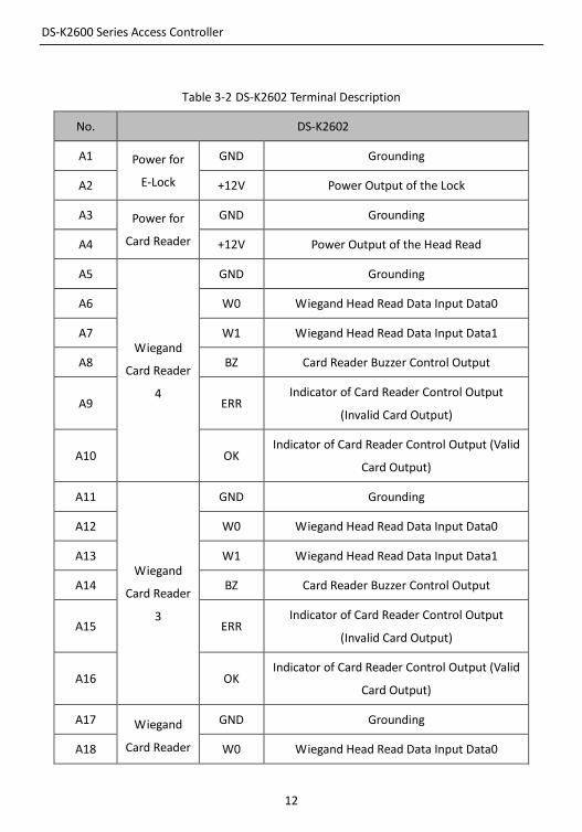
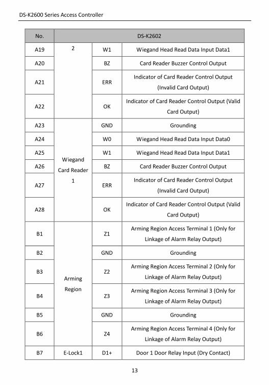
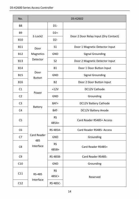
Table 3-2 DS-K2602 Terminal Description
No. DS-K2602
A1 Power for
E-Lock
GND Grounding
A2 +12V Power Output of the Lock
A3 Power for
Card Reader
GND Grounding
A4 +12V Power Output of the Head Read
A5
Wiegand
Card Reader
4
GND Grounding
A6 W0 Wiegand Head Read Data Input Data0
A7 W1 Wiegand Head Read Data Input Data1
A8 BZ Card Reader Buzzer Control Output
A9 ERR Indicator of Card Reader Control Output
(Invalid Card Output)
A10 OK Indicator of Card Reader Control Output (Valid
Card Output)
A11
Wiegand
Card Reader
3
GND Grounding
A12 W0 Wiegand Head Read Data Input Data0
A13 W1 Wiegand Head Read Data Input Data1
A14 BZ Card Reader Buzzer Control Output
A15 ERR Indicator of Card Reader Control Output
(Invalid Card Output)
A16 OK Indicator of Card Reader Control Output (Valid
Card Output)
A17 Wiegand
Card Reader
GND Grounding
A18 W0 Wiegand Head Read Data Input Data0
DS-K2600 Series Access Controller
13
No. DS-K2602
A19 2 W1 Wiegand Head Read Data Input Data1
A20 BZ Card Reader Buzzer Control Output
A21 ERR Indicator of Card Reader Control Output
(Invalid Card Output)
A22 OK Indicator of Card Reader Control Output (Valid
Card Output)
A23
Wiegand
Card Reader
1
GND Grounding
A24 W0 Wiegand Head Read Data Input Data0
A25 W1 Wiegand Head Read Data Input Data1
A26 BZ Card Reader Buzzer Control Output
A27 ERR Indicator of Card Reader Control Output
(Invalid Card Output)
A28 OK Indicator of Card Reader Control Output (Valid
Card Output)
B1
Arming
Region
Z1 Arming Region Access Terminal 1 (Only for
Linkage of Alarm Relay Output)
B2 GND Grounding
B3 Z2 Arming Region Access Terminal 2 (Only for
Linkage of Alarm Relay Output)
B4 Z3 Arming Region Access Terminal 3 (Only for
Linkage of Alarm Relay Output)
B5 GND Grounding
B6 Z4 Arming Region Access Terminal 4 (Only for
Linkage of Alarm Relay Output)
B7 E-Lock1 D1+ Door 1 Door Relay Input (Dry Contact)
DS-K2600 Series Access Controller
14
No. DS-K2602
B8 D1-
B9 E-Lock2
D2+ Door 2 Door Relay Input (Dry Contact)
B10 D2-
B11 Door
Magnetics
Detector
S1 Door 1 Magnetic Detector Input
B12 GND Signal Grounding
B13 S2 Door 2 Magnetic Detector Input
B14
Door
Button
B1 Door 1 Door Button Input
B15 GND Signal Grounding
B16 B2 Door 2 Door Button Input
C1 Power
+12V DC12V Cathode
C2 GND Grounding
C3 Battery
BAT+ DC12V Battery Cathode
C4 BAT- DC12V Battery Anode
C5
Card Reader
485
Interface
RS
485A+ Card Reader RS485+ Access
C6 RS 485A- Card Reader RS485- Access
C7 GND Grounding
C8 RS
485B+ Card Reader RS485+
C9 RS 485B- Card Reader RS485-
C10 GND Grounding
C11 RS-485
Interface
RS
485C+ Reserved
C12 RS 485C-
DS-K2600 Series Access Controller
15
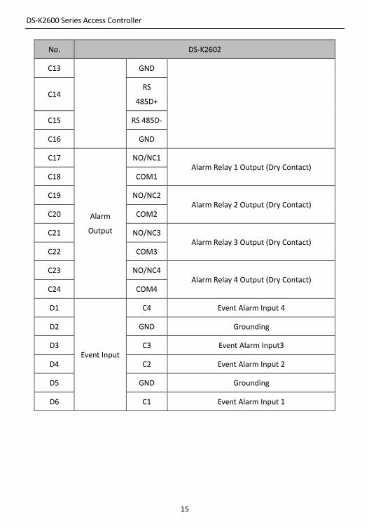
No. DS-K2602
C13 GND
C14 RS
485D+
C15 RS 485D-
C16 GND
C17
Alarm
Output
NO/NC1 Alarm Relay 1 Output (Dry Contact)
C18 COM1
C19 NO/NC2 Alarm Relay 2 Output (Dry Contact)
C20 COM2
C21 NO/NC3 Alarm Relay 3 Output (Dry Contact)
C22 COM3
C23 NO/NC4 Alarm Relay 4 Output (Dry Contact)
C24 COM4
D1
Event Input
C4 Event Alarm Input 4
D2 GND Grounding
D3 C3 Event Alarm Input3
D4 C2 Event Alarm Input 2
D5 GND Grounding
D6 C1 Event Alarm Input 1
DS-K2600 Series Access Controller
16
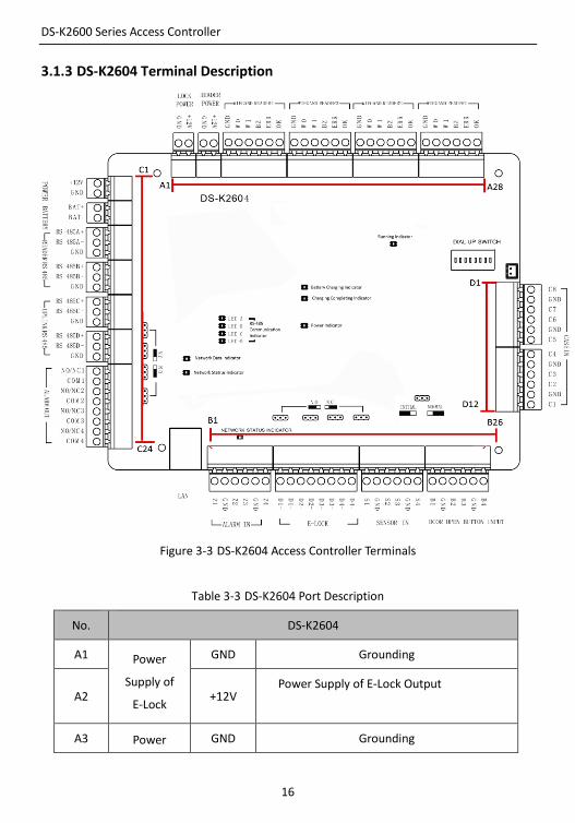
3.1.3 DS-K2604 Terminal Description
Figure 3-3 DS-K2604 Access Controller Terminals
Table 3-3 DS-K2604 Port Description
No. DS-K2604
A1 Power
Supply of
E-Lock
GND Grounding
A2 +12V Power Supply of E-Lock Output
A3 Power GND Grounding
DS-K2600 Series Access Controller
17
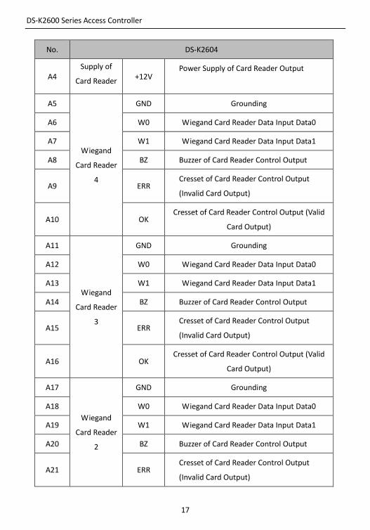
No. DS-K2604
A4 Supply of
Card Reader +12V
Power Supply of Card Reader Output
A5
Wiegand
Card Reader
4
GND Grounding
A6 W0 Wiegand Card Reader Data Input Data0
A7 W1 Wiegand Card Reader Data Input Data1
A8 BZ Buzzer of Card Reader Control Output
A9 ERR Cresset of Card Reader Control Output
(Invalid Card Output)
A10 OK Cresset of Card Reader Control Output (Valid
Card Output)
A11
Wiegand
Card Reader
3
GND Grounding
A12 W0 Wiegand Card Reader Data Input Data0
A13 W1 Wiegand Card Reader Data Input Data1
A14 BZ Buzzer of Card Reader Control Output
A15 ERR Cresset of Card Reader Control Output
(Invalid Card Output)
A16 OK Cresset of Card Reader Control Output (Valid
Card Output)
A17
Wiegand
Card Reader
2
GND Grounding
A18 W0 Wiegand Card Reader Data Input Data0
A19 W1 Wiegand Card Reader Data Input Data1
A20 BZ Buzzer of Card Reader Control Output
A21 ERR Cresset of Card Reader Control Output
(Invalid Card Output)
DS-K2600 Series Access Controller
18
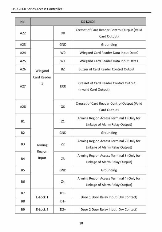
No. DS-K2604
A22 OK Cresset of Card Reader Control Output (Valid
Card Output)
A23
Wiegand
Card Reader
1
GND Grounding
A24 W0 Wiegand Card Reader Data Input Data0
A25 W1 Wiegand Card Reader Data Input Data1
A26 BZ Buzzer of Card Reader Control Output
A27 ERR Cresset of Card Reader Control Output
(Invalid Card Output)
A28 OK Cresset of Card Reader Control Output (Valid
Card Output)
B1
Arming
Region
Input
Z1 Arming Region Access Terminal 1 (Only for
Linkage of Alarm Relay Output)
B2 GND Grounding
B3 Z2 Arming Region Access Terminal 2 (Only for
Linkage of Alarm Relay Output)
B4 Z3 Arming Region Access Terminal 3 (Only for
Linkage of Alarm Relay Output)
B5 GND Grounding
B6 Z4 Arming Region Access Terminal 4 (Only for
Linkage of Alarm Relay Output)
B7 E-Lock 1
D1+ Door 1 Door Relay Input (Dry Contact)
B8 D1-
B9 E-Lock 2 D2+ Door 2 Door Relay Input (Dry Contact)
DS-K2600 Series Access Controller
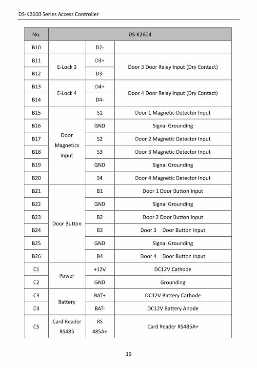
19
No. DS-K2604
B10 D2-
B11 E-Lock 3
D3+ Door 3 Door Relay Input (Dry Contact)
B12 D3-
B13 E-Lock 4
D4+ Door 4 Door Relay Input (Dry Contact)
B14 D4-
B15
Door
Magnetics
Input
S1 Door 1 Magnetic Detector Input
B16 GND Signal Grounding
B17 S2 Door 2 Magnetic Detector Input
B18 S3 Door 3 Magnetic Detector Input
B19 GND Signal Grounding
B20 S4 Door 4 Magnetic Detector Input
B21
Door Button
B1 Door 1 Door Button Input
B22 GND Signal Grounding
B23 B2 Door 2 Door Button Input
B24 B3 Door 3 Door Button Input
B25 GND Signal Grounding
B26 B4 Door 4 Door Button Input
C1 Power
+12V DC12V Cathode
C2 GND Grounding
C3 Battery
BAT+ DC12V Battery Cathode
C4 BAT- DC12V Battery Anode
C5 Card Reader
RS485
RS
485A+ Card Reader RS485A+
DS-K2600 Series Access Controller
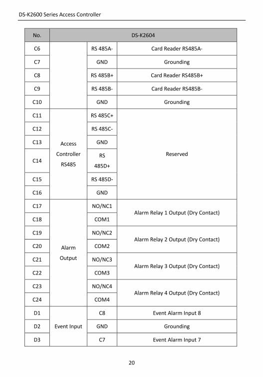
20
No. DS-K2604
C6 RS 485A- Card Reader RS485A-
C7 GND Grounding
C8 RS 485B+ Card Reader RS485B+
C9 RS 485B- Card Reader RS485B-
C10 GND Grounding
C11
Access
Controller
RS485
RS 485C+
Reserved
C12 RS 485C-
C13 GND
C14 RS
485D+
C15 RS 485D-
C16 GND
C17
Alarm
Output
NO/NC1 Alarm Relay 1 Output (Dry Contact)
C18 COM1
C19 NO/NC2 Alarm Relay 2 Output (Dry Contact)
C20 COM2
C21 NO/NC3 Alarm Relay 3 Output (Dry Contact)
C22 COM3
C23 NO/NC4 Alarm Relay 4 Output (Dry Contact)
C24 COM4
D1
Event Input
C8 Event Alarm Input 8
D2 GND Grounding
D3 C7 Event Alarm Input 7
DS-K2600 Series Access Controller
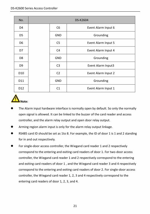
21
No. DS-K2604
D4 C6 Event Alarm Input 6
D5 GND Grounding
D6 C5 Event Alarm Input 5
D7 C4 Event Alarm Input 4
D8 GND Grounding
D9 C3 Event Alarm Input3
D10 C2 Event Alarm Input 2
D11 GND Grounding
D12 C1 Event Alarm Input 1
Note:
The Alarm input hardware interface is normally open by default. So only the normally
open signal is allowed. It can be linked to the buzzer of the card reader and access
controller, and the alarm relay output and open door relay output.
Arming region alarm input is only for the alarm relay output linkage.
RS485 card ID should be set as 1to 8. For example, the ID of door 1 is 1 and 2 standing
for in and out respectively.
For single-door access controller, the Wiegand card reader 1 and 2 respectively
correspond to the entering and exiting card readers of door 1. For two-door access
controller, the Wiegand card reader 1 and 2 respectively correspond to the entering
and exiting card readers of door 1 , and the Wiegand card reader 3 and 4 respectively
correspond to the entering and exiting card readers of door 2. For single-door access
controller, the Wiegand card reader 1, 2, 3 and 4 respectively correspond to the
entering card readers of door 1, 2, 3, and 4.
DS-K2600 Series Access Controller
22
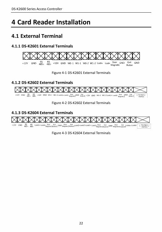
4 Card Reader Installation
4.1 External Terminal
4.1.1 DS-K2601 External Terminals
Figure 4-1 DS-K2601 External Terminals
4.1.2 DS-K2602 External Terminals
Figure 4-2 DS-K2602 External Terminals
4.1.3 DS-K2604 External Terminals
Figure 4-3 DS-K2604 External Terminals
DS-K2600 Series Access Controller
23
4.2 Card Reader Installation
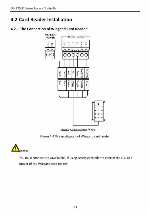
4.2.1 The Connection of Wiegand Card Reader
Figure 4-4 Wiring diagram of Wiegand card reader
Note:
You must connect the OK/ERR/BZ, if using access controller to control the LED and
buzzer of the Wiegand card reader.
DS-K2600 Series Access Controller
24
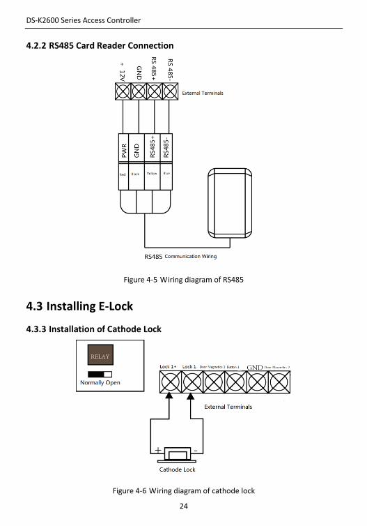
4.2.2 RS485 Card Reader Connection
Figure 4-5 Wiring diagram of RS485
4.3 Installing E-Lock
4.3.3 Installation of Cathode Lock
Figure 4-6 Wiring diagram of cathode lock
DS-K2600 Series Access Controller
25
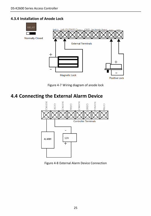
4.3.4 Installation of Anode Lock
Figure 4-7 Wiring diagram of anode lock
4.4 Connecting the External Alarm Device
Figure 4-8 External Alarm Device Connection
DS-K2600 Series Access Controller
26
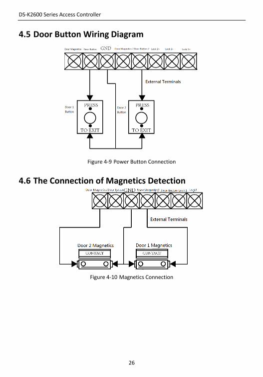
4.5 Door Button Wiring Diagram
Figure 4-9 Power Button Connection
4.6 The Connection of Magnetics Detection
Figure 4-10 Magnetics Connection
DS-K2600 Series Access Controller
27
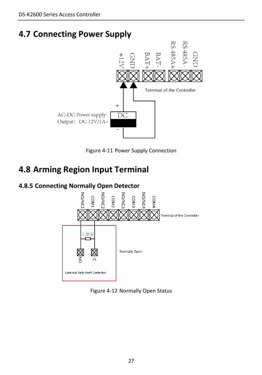
4.7 Connecting Power Supply
Figure 4-11 Power Supply Connection
4.8 Arming Region Input Terminal
4.8.5 Connecting Normally Open Detector
Figure 4-12 Normally Open Status
DS-K2600 Series Access Controller
28
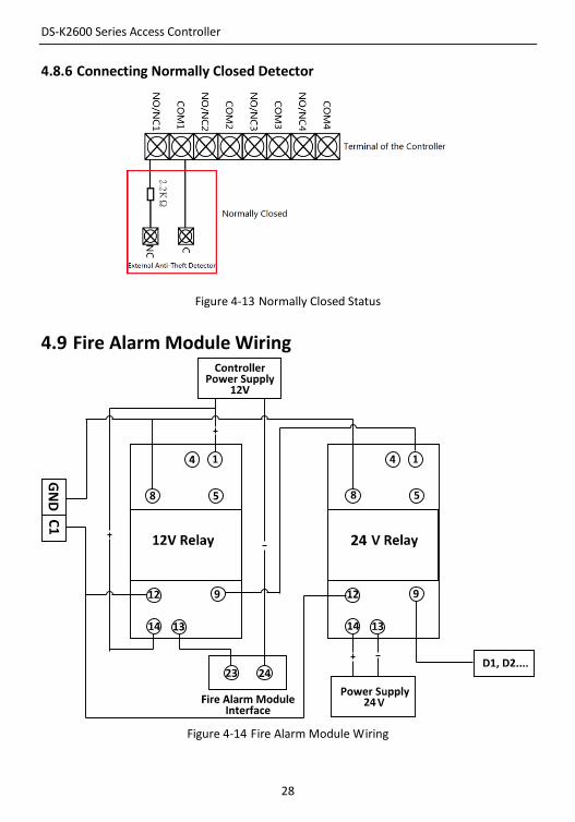
4.8.6 Connecting Normally Closed Detector
Figure 4-13 Normally Closed Status
4.9 Fire Alarm Module Wiring
Figure 4-14 Fire Alarm Module Wiring
DS-K2600 Series Access Controller
29
5 Settings
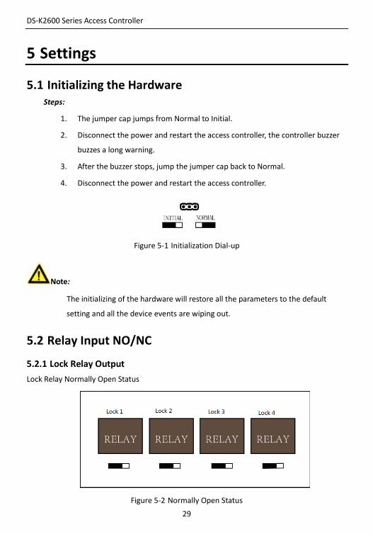
5.1 Initializing the Hardware Steps:
1. The jumper cap jumps from Normal to Initial.
2. Disconnect the power and restart the access controller, the controller buzzer
buzzes a long warning.
3. After the buzzer stops, jump the jumper cap back to Normal.
4. Disconnect the power and restart the access controller.
Figure 5-1 Initialization Dial-up
Note:
The initializing of the hardware will restore all the parameters to the default
setting and all the device events are wiping out.
5.2 Relay Input NO/NC
5.2.1 Lock Relay Output
Lock Relay Normally Open Status
Figure 5-2 Normally Open Status
DS-K2600 Series Access Controller
30
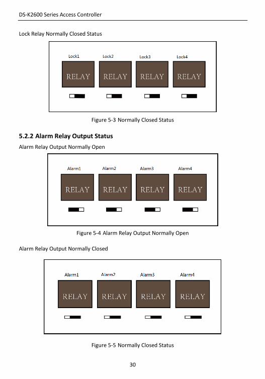
Lock Relay Normally Closed Status
Figure 5-3 Normally Closed Status
5.2.2 Alarm Relay Output Status
Alarm Relay Output Normally Open
Figure 5-4 Alarm Relay Output Normally Open
Alarm Relay Output Normally Closed
Figure 5-5 Normally Closed Status
DS-K2600 Series Access Controller
31
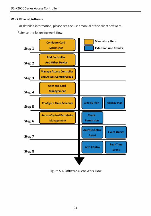
Work Flow of Software
For detailed information, please see the user manual of the client software.
Refer to the following work flow:
Figure 5-6 Software Client Work Flow
DS-K2600 Series Access Controller
32
6 Activating the Control Panel Purpose:
You are required to activate the control panel first before you can use the
control panel.
Activation via SADP, and Activation via client software are supported.
6.1 Activation via SADP Software SADP software is used for detecting the online device, activating the device,
and resetting the password.
Get the SADP software from the supplied disk or the official website, and
install the SADP according to the prompts. Follow the steps to activate the
control panel.
Steps:
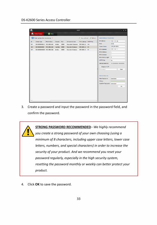
1. Run the SADP software to search the online devices.
2. Check the device status from the device list, and select an inactive device.
DS-K2600 Series Access Controller
33
3. Create a password and input the password in the password field, and
confirm the password.
STRONG PASSWORD RECOMMENDED– We highly recommend
you create a strong password of your own choosing (using a
minimum of 8 characters, including upper case letters, lower case
letters, numbers, and special characters) in order to increase the
security of your product. And we recommend you reset your
password regularly, especially in the high security system,
resetting the password monthly or weekly can better protect your
product.
4. Click OK to save the password.
DS-K2600 Series Access Controller
34
You can check whether the activation is completed on the pop-up window.
If activation failed, please make sure that the password meets the
requirement and then try again.
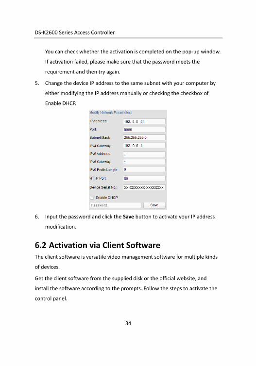
5. Change the device IP address to the same subnet with your computer by
either modifying the IP address manually or checking the checkbox of
Enable DHCP.
6. Input the password and click the Save button to activate your IP address
modification.
6.2 Activation via Client Software The client software is versatile video management software for multiple kinds
of devices.
Get the client software from the supplied disk or the official website, and
install the software according to the prompts. Follow the steps to activate the
control panel.
DS-K2600 Series Access Controller
35
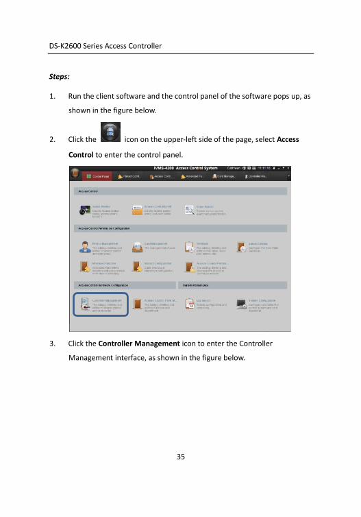
Steps:
1. Run the client software and the control panel of the software pops up, as
shown in the figure below.
2. Click the icon on the upper-left side of the page, select Access
Control to enter the control panel.
3. Click the Controller Management icon to enter the Controller
Management interface, as shown in the figure below.

DS-K2600 Series Access Controller
36
4. Check the device status from the device list, and select an inactive
device.
5. Click the Activate button to pop up the Activation interface.
6. Create a password and input the password in the password field, and
confirm the password.
DS-K2600 Series Access Controller
37
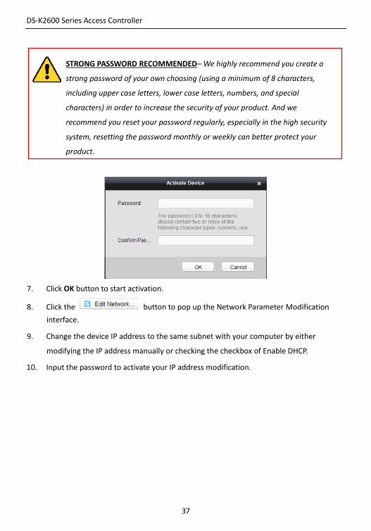
STRONG PASSWORD RECOMMENDED– We highly recommend you create a
strong password of your own choosing (using a minimum of 8 characters,
including upper case letters, lower case letters, numbers, and special
characters) in order to increase the security of your product. And we
recommend you reset your password regularly, especially in the high security
system, resetting the password monthly or weekly can better protect your
product.
7. Click OK button to start activation.
8. Click the button to pop up the Network Parameter Modification
interface.
9. Change the device IP address to the same subnet with your computer by either
modifying the IP address manually or checking the checkbox of Enable DHCP.
10. Input the password to activate your IP address modification.
DS-K2600 Series Access Controller
38
7 Client Operation
7.1 Overview of Access Control System
7.1.1 Description
The access control system is a system of configuring permission of door access. It provides
multiple functionalities, including access controller management, people/card management,
permission configuration, door status management, event search, etc.
This user manual describes the function, configuration and operation steps of Access Control
System. To ensure the properness of usage and stability of the system, please refer to the
contents below and read the manual carefully before installation and operation.
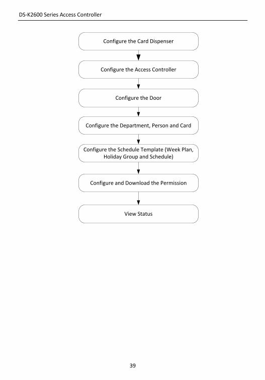
7.1.2 Configuration Flow
Refer to the following flow chart for the configuration order.
DS-K2600 Series Access Controller
39
Configure the Card Dispenser
Configure the Access Controller
Configure the Door
Configure the Department, Person and Card
Configure the Schedule Template (Week Plan, Holiday Group and Schedule)
Configure and Download the Permission
View Status
DS-K2600 Series Access Controller
40
7.2 Device Management
7.2.1 Controller Management
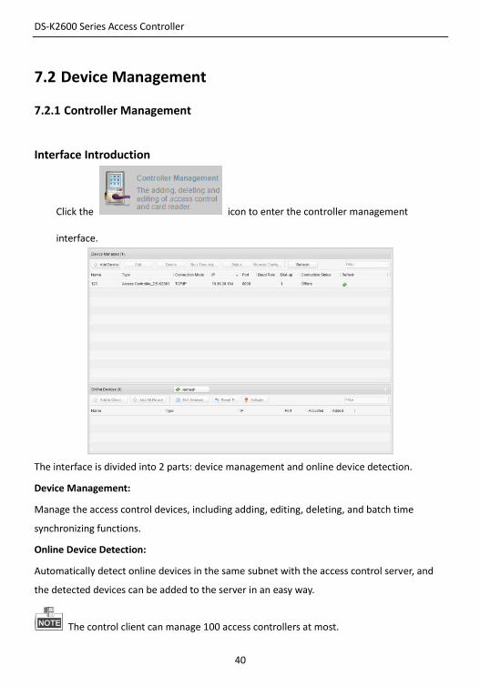
Interface Introduction
Click the icon to enter the controller management
interface.
The interface is divided into 2 parts: device management and online device detection.
Device Management:
Manage the access control devices, including adding, editing, deleting, and batch time
synchronizing functions.
Online Device Detection:
Automatically detect online devices in the same subnet with the access control server, and
the detected devices can be added to the server in an easy way.
The control client can manage 100 access controllers at most.
DS-K2600 Series Access Controller
41
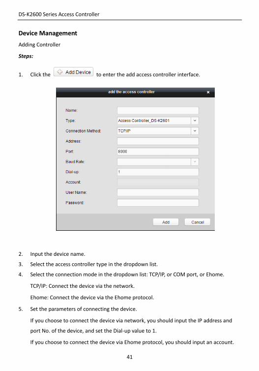
Device Management
Adding Controller
Steps:
1. Click the to enter the add access controller interface.
2. Input the device name.
3. Select the access controller type in the dropdown list.
4. Select the connection mode in the dropdown list: TCP/IP, or COM port, or Ehome.
TCP/IP: Connect the device via the network.
Ehome: Connect the device via the Ehome protocol.
5. Set the parameters of connecting the device.
If you choose to connect the device via network, you should input the IP address and
port No. of the device, and set the Dial-up value to 1.
If you choose to connect the device via Ehome protocol, you should input an account.
DS-K2600 Series Access Controller
42
For the detailed information about the account, refer to 15.1.3.
6. Click the button to finish adding.
You can click Status to check the detailed status of the controller, and click Remote
Configuration to configure the settings of the controller.
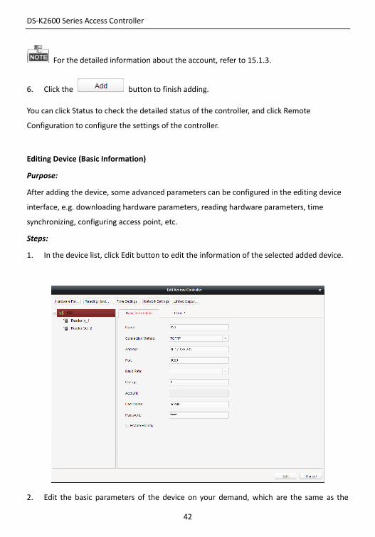
Editing Device (Basic Information)
Purpose:
After adding the device, some advanced parameters can be configured in the editing device
interface, e.g. downloading hardware parameters, reading hardware parameters, time
synchronizing, configuring access point, etc.
Steps:
1. In the device list, click Edit button to edit the information of the selected added device.
2. Edit the basic parameters of the device on your demand, which are the same as the
DS-K2600 Series Access Controller
43
ones when adding the device.
3. (Optional) Check the checkbox of Enable Holiday to enable the holiday parameters
when downloading permissions.
4. Click the Edit button to finish editing.
5. Click the Hardware Parameters Downloading button to download the updated
parameters to the local memory of the device.
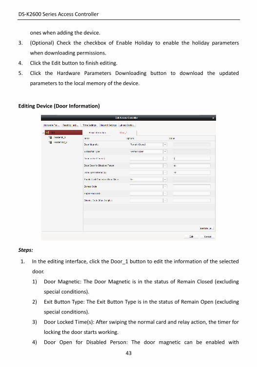
Editing Device (Door Information)
Steps:
1. In the editing interface, click the Door_1 button to edit the information of the selected
door.
1) Door Magnetic: The Door Magnetic is in the status of Remain Closed (excluding
special conditions).
2) Exit Button Type: The Exit Button Type is in the status of Remain Open (excluding
special conditions).
3) Door Locked Time(s): After swiping the normal card and relay action, the timer for
locking the door starts working.
4) Door Open for Disabled Person: The door magnetic can be enabled with
DS-K2600 Series Access Controller
44
appropriate delay after disabled person swipes the card.
5) Door Open Timeout(s): The alarm can be triggered if the door has not been close
6) Enable Lock Door when Door Close: This function has not been supported yet.
7) Duress Code: The door can open by inputting the duress code when there is a
duress. At the same time, the access system can report the duress event.
8) Super Password: The specific person can open the door by inputting the super
password.
2. Click the Restore Default Value to restore all parameters into default settings.
3. Click the Edit button to save parameters.
4. Click the Hardware Parameters Downloading button to download the updated
parameters to the local memory of the device.
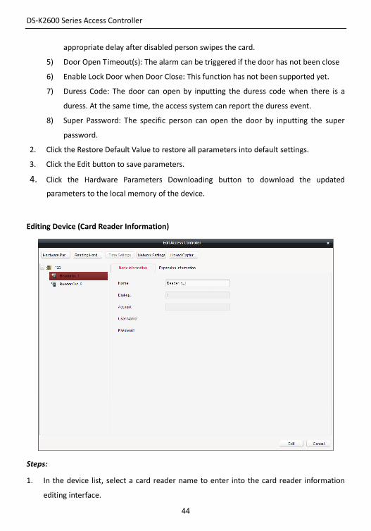
Editing Device (Card Reader Information)
Steps:
1. In the device list, select a card reader name to enter into the card reader information
editing interface.
DS-K2600 Series Access Controller
45
2. Click the Basic Information button to edit the basic information about the card reader.
3. Click the Expansion Information button to edit the expansion information about the
card reader.
4. Click the Edit button to save parameters.
5. Click the Hardware Parameters Downloading button to download the updated
parameters to the local memory of the device.
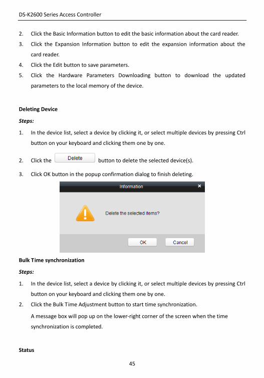
Deleting Device
Steps:
1. In the device list, select a device by clicking it, or select multiple devices by pressing Ctrl
button on your keyboard and clicking them one by one.
2. Click the button to delete the selected device(s).
3. Click OK button in the popup confirmation dialog to finish deleting.
Bulk Time synchronization
Steps:
1. In the device list, select a device by clicking it, or select multiple devices by pressing Ctrl
button on your keyboard and clicking them one by one.
2. Click the Bulk Time Adjustment button to start time synchronization.
A message box will pop up on the lower-right corner of the screen when the time
synchronization is completed.
Status
DS-K2600 Series Access Controller
46
In the device list, you can click Status button to enter view the status.
Steps:
1) Door Status: The status of the connected door.
2) Host Status: The status of the host, including Storage Battery Power Voltage, Device
Power Supply Status, Multi-door Interlocking Status, Anti-passing Back Status, Host
Anti-Tamper Status.
3) Card Reader Status: The status of card reader.
4) Alarm Input Status: The alarm input status of each port.
5) Alarm Output Status: The alarm output status of each port.
6) Event Sensor Status: The event status of each port.
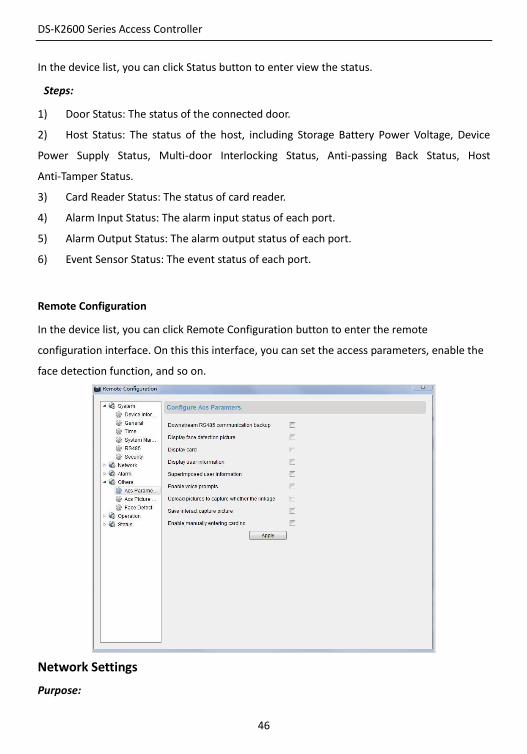
Remote Configuration
In the device list, you can click Remote Configuration button to enter the remote
configuration interface. On this this interface, you can set the access parameters, enable the
face detection function, and so on.
Network Settings
Purpose:
DS-K2600 Series Access Controller
47
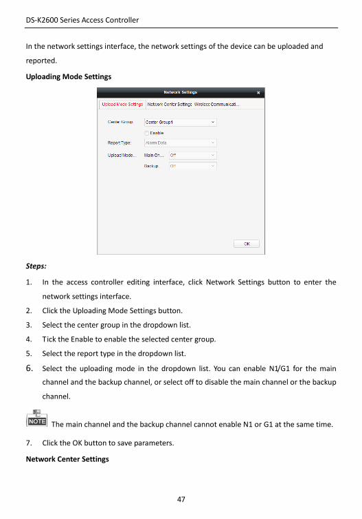
In the network settings interface, the network settings of the device can be uploaded and
reported.
Uploading Mode Settings
Steps:
1. In the access controller editing interface, click Network Settings button to enter the
network settings interface.
2. Click the Uploading Mode Settings button.
3. Select the center group in the dropdown list.
4. Tick the Enable to enable the selected center group.
5. Select the report type in the dropdown list.
6. Select the uploading mode in the dropdown list. You can enable N1/G1 for the main
channel and the backup channel, or select off to disable the main channel or the backup
channel.
The main channel and the backup channel cannot enable N1 or G1 at the same time.
7. Click the OK button to save parameters.
Network Center Settings
DS-K2600 Series Access Controller
48
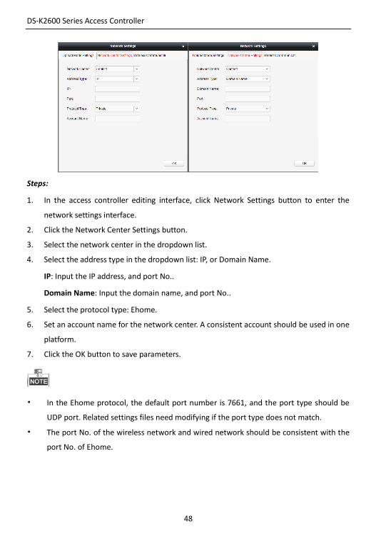
Steps:
1. In the access controller editing interface, click Network Settings button to enter the
network settings interface.
2. Click the Network Center Settings button.
3. Select the network center in the dropdown list.
4. Select the address type in the dropdown list: IP, or Domain Name.
IP: Input the IP address, and port No..
Domain Name: Input the domain name, and port No..
5. Select the protocol type: Ehome.
6. Set an account name for the network center. A consistent account should be used in one
platform.
7. Click the OK button to save parameters.
• In the Ehome protocol, the default port number is 7661, and the port type should be
UDP port. Related settings files need modifying if the port type does not match.
• The port No. of the wireless network and wired network should be consistent with the
port No. of Ehome.
DS-K2600 Series Access Controller
49
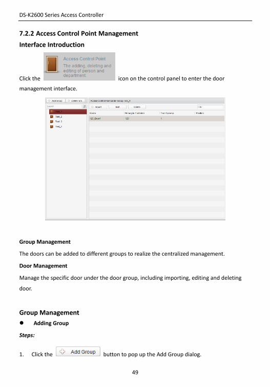
7.2.2 Access Control Point Management
Interface Introduction
Click the icon on the control panel to enter the door
management interface.
Group Management
The doors can be added to different groups to realize the centralized management.
Door Management
Manage the specific door under the door group, including importing, editing and deleting
door.
Group Management
Adding Group
Steps:
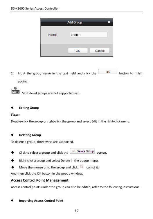
1. Click the button to pop up the Add Group dialog.
DS-K2600 Series Access Controller
50
2. Input the group name in the text field and click the button to finish
adding.
Multi-level groups are not supported yet.
Editing Group
Steps:
Double-click the group or right-click the group and select Edit in the right-click menu.
Deleting Group
To delete a group, three ways are supported.
Click to select a group and click the button.
Right-click a group and select Delete in the popup menu.
Move the mouse onto the group and click icon of it.
And then click the OK button in the popup window.
Access Control Point Management
Access control points under the group can also be edited, refer to the following instructions.
Importing Access Control Point
DS-K2600 Series Access Controller
51
Steps:
1. Click the button to pop up the access control point importing
interface.
2. Select an access control point to import by clicking it.
3. Click to select a group in the right side bar to import to.
4. Click button to import the selected access control points or click
to import all the available access control points.
You can click button on the upper-right corner of the window to create a new
group.
The control client can manage 100 access control points at most.
Editing Access Control Point
Steps:
1. Click to select an access control point in the list and click the button to
edit the access control point.
2. Edit the Door Name and Position.
3. Click button to finish editing.
you can also enter the Edit interface by double clicking the door from the list.
Deleting Access Control Point
Several ways are supported to delete the access control point, as shown below.
Click to select a group in the group list, select door(s) under it, and click
button.

DS-K2600 Series Access Controller
52
Click to select a group in the group list, and click button to delete all
access control points under the group.
Move the mouse onto a group in the group list, and click button to delete all
access control points under the group.
You can also edit/delete a door on the Import Access Control Point panel.
Steps:
1. Select a control point on the Group panel.
2. Click the / icon to enter the Edit Access Control Point panel or to delete the
control point.
7.3 Permission Management
7.3.1 Person Management
Interface Introduction
Click the icon on the control panel of the software.
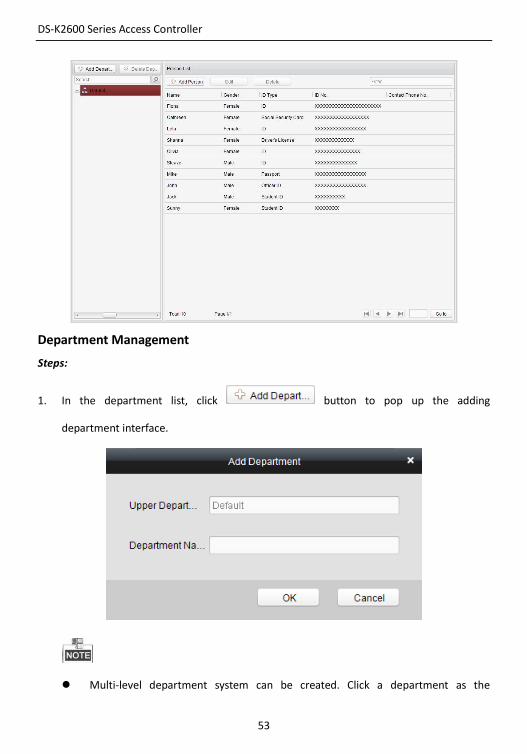
Adding, editing, deleting and filtering of the department and person are supported in this
interface.
DS-K2600 Series Access Controller
53
Department Management
Steps:
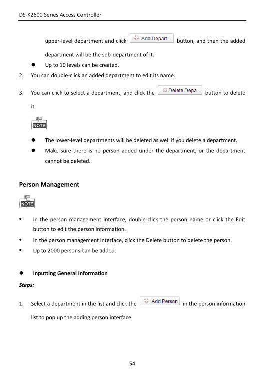
1. In the department list, click button to pop up the adding
department interface.
Multi-level department system can be created. Click a department as the
DS-K2600 Series Access Controller
54
upper-level department and click button, and then the added
department will be the sub-department of it.
Up to 10 levels can be created.
2. You can double-click an added department to edit its name.
3. You can click to select a department, and click the button to delete
it.
The lower-level departments will be deleted as well if you delete a department.
Make sure there is no person added under the department, or the department
cannot be deleted.
Person Management
• In the person management interface, double-click the person name or click the Edit
button to edit the person information.
• In the person management interface, click the Delete button to delete the person.
• Up to 2000 persons ban be added.
Inputting General Information
Steps:
1. Select a department in the list and click the in the person information
list to pop up the adding person interface.

DS-K2600 Series Access Controller
55
2. Input the Person Name (required), Gender, ID Card, etc., upload the photo of the person
and click the icon to finish adding.
The format of the photo should be .jpg, or .jpeg.
3. You can double-click an added person to edit its information.
4. You can click to select a person, and click the button to delete it.
If a card is associated with the current person, the association will be invalid after the
person is deleted.
DS-K2600 Series Access Controller
56
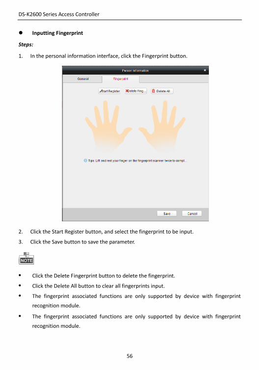
Inputting Fingerprint
Steps:
1. In the personal information interface, click the Fingerprint button.
2. Click the Start Register button, and select the fingerprint to be input.
3. Click the Save button to save the parameter.
• Click the Delete Fingerprint button to delete the fingerprint.
• Click the Delete All button to clear all fingerprints input.
• The fingerprint associated functions are only supported by device with fingerprint
recognition module.
• The fingerprint associated functions are only supported by device with fingerprint
recognition module.
DS-K2600 Series Access Controller
57
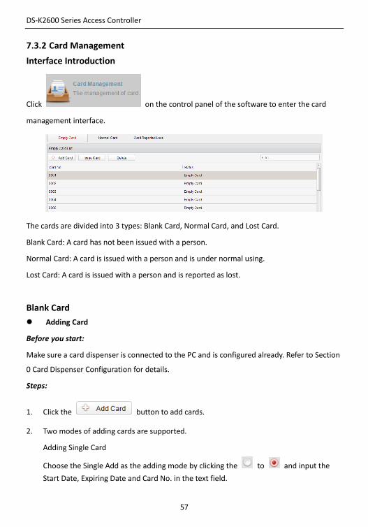
7.3.2 Card Management
Interface Introduction
Click on the control panel of the software to enter the card
management interface.
The cards are divided into 3 types: Blank Card, Normal Card, and Lost Card.
Blank Card: A card has not been issued with a person.
Normal Card: A card is issued with a person and is under normal using.
Lost Card: A card is issued with a person and is reported as lost.
Blank Card
Adding Card
Before you start:
Make sure a card dispenser is connected to the PC and is configured already. Refer to Section
0 Card Dispenser Configuration for details.
Steps:
1. Click the button to add cards.
2. Two modes of adding cards are supported.
Adding Single Card
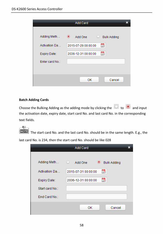
Choose the Single Add as the adding mode by clicking the to and input the
Start Date, Expiring Date and Card No. in the text field.
DS-K2600 Series Access Controller
58
Batch Adding Cards
Choose the Bulking Adding as the adding mode by clicking the to and input
the activation date, expiry date, start card No. and last card No. in the corresponding
text fields.
The start card No. and the last card No. should be in the same length. E.g., the
last card No. is 234, then the start card No. should be like 028
DS-K2600 Series Access Controller
59
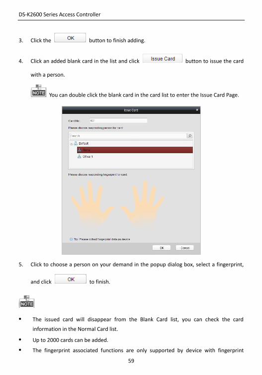
3. Click the button to finish adding.
4. Click an added blank card in the list and click button to issue the card
with a person.
You can double click the blank card in the card list to enter the Issue Card Page.
5. Click to choose a person on your demand in the popup dialog box, select a fingerprint,
and click to finish.
• The issued card will disappear from the Blank Card list, you can check the card
information in the Normal Card list.
• Up to 2000 cards can be added.
• The fingerprint associated functions are only supported by device with fingerprint
DS-K2600 Series Access Controller
60
recognition module.
Deleting Card
You can click an added blank card in the list and click button to delete the
selected card.
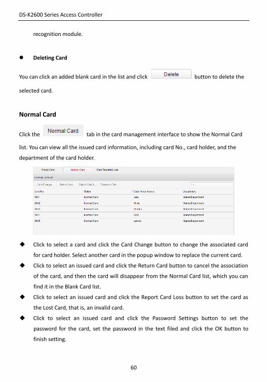
Normal Card
Click the tab in the card management interface to show the Normal Card
list. You can view all the issued card information, including card No., card holder, and the
department of the card holder.
Click to select a card and click the Card Change button to change the associated card
for card holder. Select another card in the popup window to replace the current card.
Click to select an issued card and click the Return Card button to cancel the association
of the card, and then the card will disappear from the Normal Card list, which you can
find it in the Blank Card list.
Click to select an issued card and click the Report Card Loss button to set the card as
the Lost Card, that is, an invalid card.
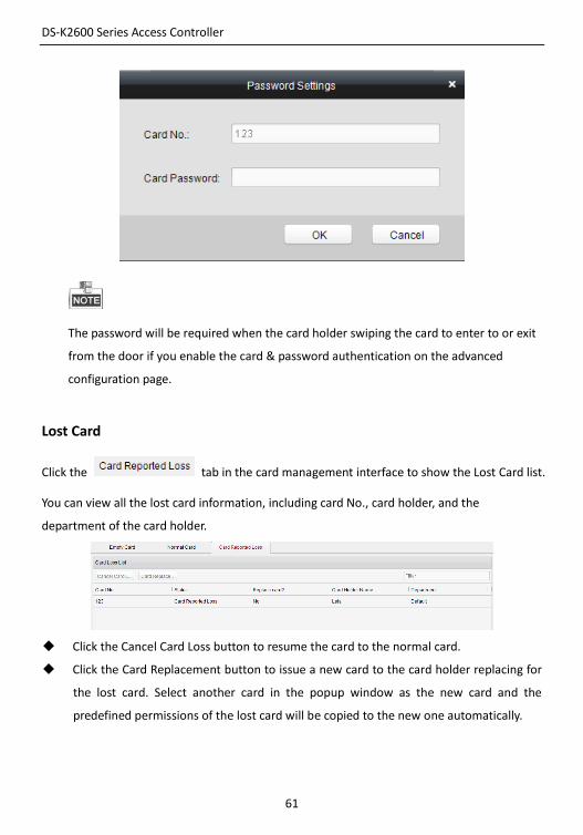
Click to select an issued card and click the Password Settings button to set the
password for the card, set the password in the text filed and click the OK button to
finish setting.
DS-K2600 Series Access Controller
61
The password will be required when the card holder swiping the card to enter to or exit
from the door if you enable the card & password authentication on the advanced
configuration page.
Lost Card
Click the tab in the card management interface to show the Lost Card list.
You can view all the lost card information, including card No., card holder, and the
department of the card holder.
Click the Cancel Card Loss button to resume the card to the normal card.
Click the Card Replacement button to issue a new card to the card holder replacing for
the lost card. Select another card in the popup window as the new card and the
predefined permissions of the lost card will be copied to the new one automatically.
DS-K2600 Series Access Controller
62
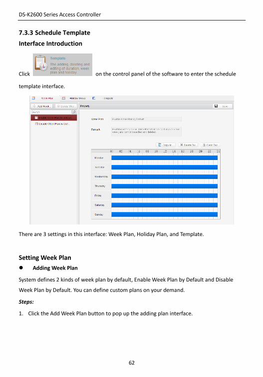
7.3.3 Schedule Template
Interface Introduction
Click on the control panel of the software to enter the schedule
template interface.
There are 3 settings in this interface: Week Plan, Holiday Plan, and Template.
Setting Week Plan
Adding Week Plan
System defines 2 kinds of week plan by default, Enable Week Plan by Default and Disable
Week Plan by Default. You can define custom plans on your demand.
Steps:
1. Click the Add Week Plan button to pop up the adding plan interface.

DS-K2600 Series Access Controller
63
2. Input the name of week plan and click the OK button to add the week plan.
3. Select a week plan in the plan list on the left-side of the window to edit.
4. Click and drag your mouse on a day to draw a blue bar on the schedule, which means in
that period of time, the configured permission is activated.
5. Repeat the above step to configure other time periods.
Or you can select a configured day and click the Copy to Week button to copy the same
settings to the whole week.
Deleting Week Plan
Click to select a configured duration and click the Delete Duration button to delete
it.
Click the Clear Duration button to clear all the configured durations, while the week
plan still exists.
Click the Delete Week Plan button to delete the week plan directly.
Setting Holiday Group
Adding Holiday Group
Steps:
1. Click the Add Holiday Group button to pop up the adding holiday group interface.
DS-K2600 Series Access Controller
64
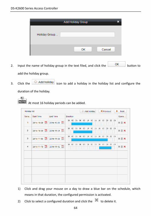
2. Input the name of holiday group in the text filed, and click the button to
add the holiday group.
3. Click the icon to add a holiday in the holiday list and configure the
duration of the holiday.
At most 16 holiday periods can be added.
1) Click and drag your mouse on a day to draw a blue bar on the schedule, which
means in that duration, the configured permission is activated.
2) Click to select a configured duration and click the to delete it.
DS-K2600 Series Access Controller
65
3) Click the to clear all the configured durations, while the holiday still exists.
4) Click the to delete the holiday directly.
4. Click the button to save the settings.
The holidays cannot be overlapped with each other.
Setting Schedule Template
The schedule consists of week plan and holiday group; you can only choose which plan and
group to enable in the schedule template configuration interface. Configure the week plan
and holiday group before configuring the schedule template.
The priority of holiday group schedule is higher than the week plan.
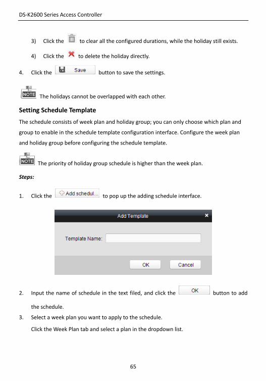
Steps:
1. Click the to pop up the adding schedule interface.
2. Input the name of schedule in the text filed, and click the button to add
the schedule.
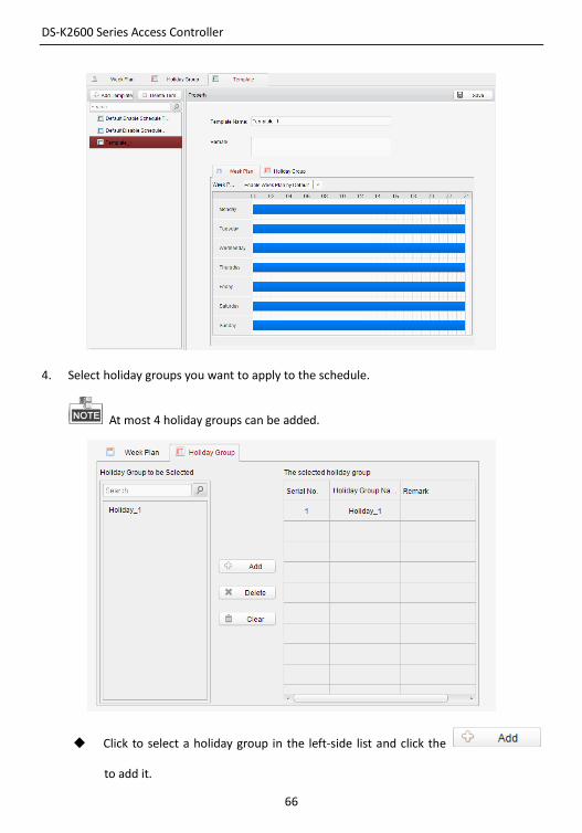
3. Select a week plan you want to apply to the schedule.
Click the Week Plan tab and select a plan in the dropdown list.
DS-K2600 Series Access Controller
66
4. Select holiday groups you want to apply to the schedule.
At most 4 holiday groups can be added.
Click to select a holiday group in the left-side list and click the
to add it.
DS-K2600 Series Access Controller
67
Click to select an added holiday group in the right-side list and click the
to delete it.
Click the to delete all the added holiday groups.
5. Click the button to save the settings.
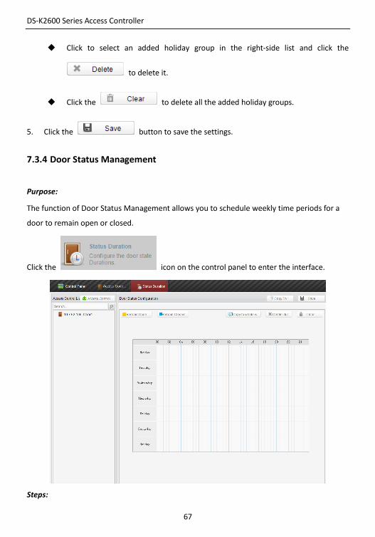
7.3.4 Door Status Management
Purpose:
The function of Door Status Management allows you to schedule weekly time periods for a
door to remain open or closed.
Click the icon on the control panel to enter the interface.
Steps:
DS-K2600 Series Access Controller
68
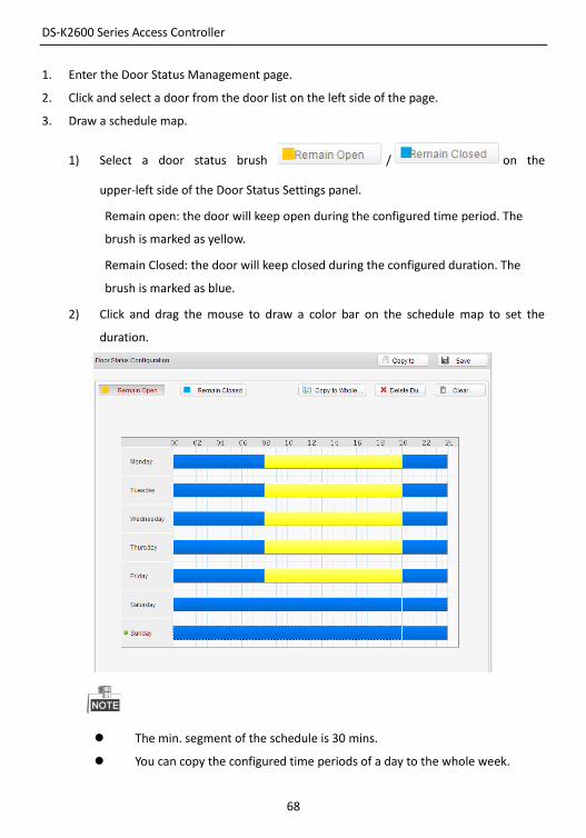
1. Enter the Door Status Management page.
2. Click and select a door from the door list on the left side of the page.
3. Draw a schedule map.
1) Select a door status brush / on the
upper-left side of the Door Status Settings panel.
Remain open: the door will keep open during the configured time period. The
brush is marked as yellow.
Remain Closed: the door will keep closed during the configured duration. The
brush is marked as blue.
2) Click and drag the mouse to draw a color bar on the schedule map to set the
duration.
The min. segment of the schedule is 30 mins.
You can copy the configured time periods of a day to the whole week.
DS-K2600 Series Access Controller
69
Steps:
1. Select a day which has already been configured.
2. Click on to copy the time periods to the whole week.
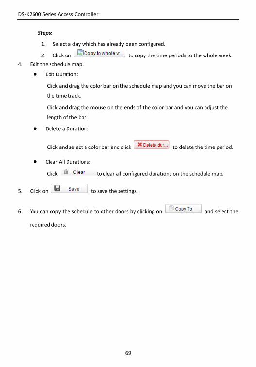
4. Edit the schedule map.
Edit Duration:
Click and drag the color bar on the schedule map and you can move the bar on
the time track.
Click and drag the mouse on the ends of the color bar and you can adjust the
length of the bar.
Delete a Duration:
Click and select a color bar and click to delete the time period.
Clear All Durations:
Click to clear all configured durations on the schedule map.
5. Click on to save the settings.
6. You can copy the schedule to other doors by clicking on and select the
required doors.
DS-K2600 Series Access Controller
70
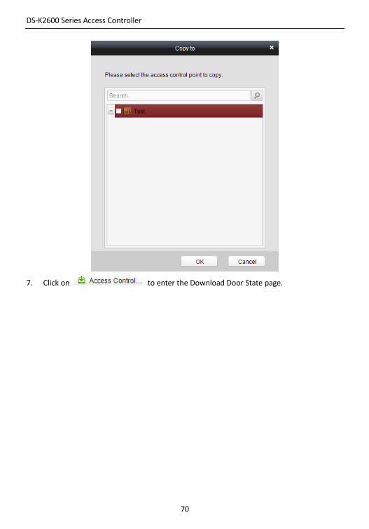
7. Click on to enter the Download Door State page.

DS-K2600 Series Access Controller
71
8. Select a control point and click OK to download the settings to the system.
7.3.5 Interact Configuration
Click on the control panel of the software to enter the interact
configuration interface.
DS-K2600 Series Access Controller
72
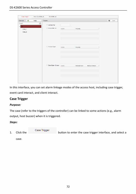
In this interface, you can set alarm linkage modes of the access host, including case trigger,
event card interact, and client interact.
Case Trigger
Purpose:
The case (refer to the triggers of the controller) can be linked to some actions (e.g., alarm
output, host buzzer) when it is triggered.
Steps:
1. Click the button to enter the case trigger interface, and select a
case.
DS-K2600 Series Access Controller
73
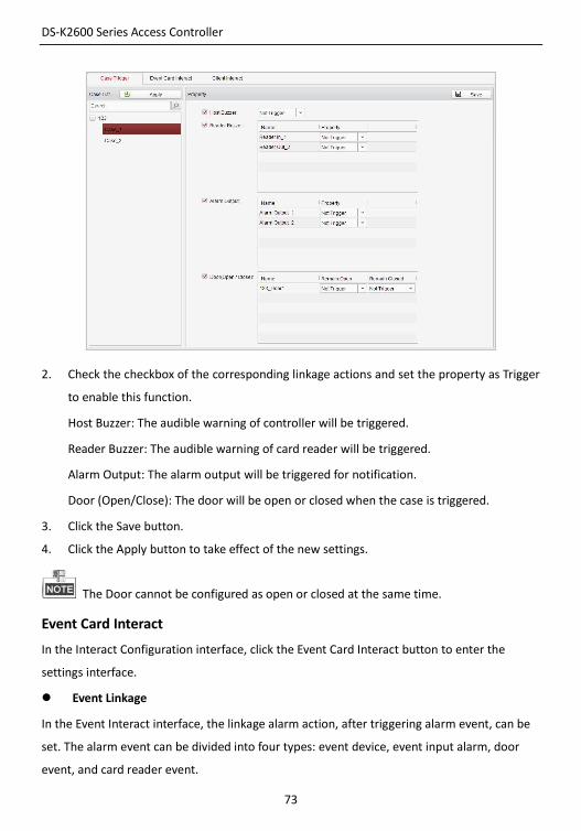
2. Check the checkbox of the corresponding linkage actions and set the property as Trigger
to enable this function.
Host Buzzer: The audible warning of controller will be triggered.
Reader Buzzer: The audible warning of card reader will be triggered.
Alarm Output: The alarm output will be triggered for notification.
Door (Open/Close): The door will be open or closed when the case is triggered.
3. Click the Save button.
4. Click the Apply button to take effect of the new settings.
The Door cannot be configured as open or closed at the same time.
Event Card Interact
In the Interact Configuration interface, click the Event Card Interact button to enter the
settings interface.
Event Linkage
In the Event Interact interface, the linkage alarm action, after triggering alarm event, can be
set. The alarm event can be divided into four types: event device, event input alarm, door
event, and card reader event.
DS-K2600 Series Access Controller
74
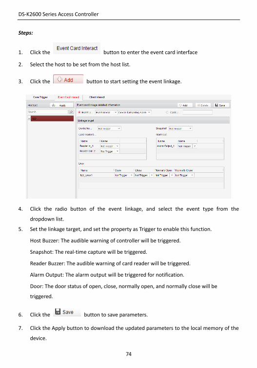
Steps:
1. Click the button to enter the event card interface
2. Select the host to be set from the host list.
3. Click the button to start setting the event linkage.
4. Click the radio button of the event linkage, and select the event type from the
dropdown list.
5. Set the linkage target, and set the property as Trigger to enable this function.
Host Buzzer: The audible warning of controller will be triggered.
Snapshot: The real-time capture will be triggered.
Reader Buzzer: The audible warning of card reader will be triggered.
Alarm Output: The alarm output will be triggered for notification.
Door: The door status of open, close, normally open, and normally close will be
triggered.
6. Click the button to save parameters.
7. Click the Apply button to download the updated parameters to the local memory of the
device.
DS-K2600 Series Access Controller
75
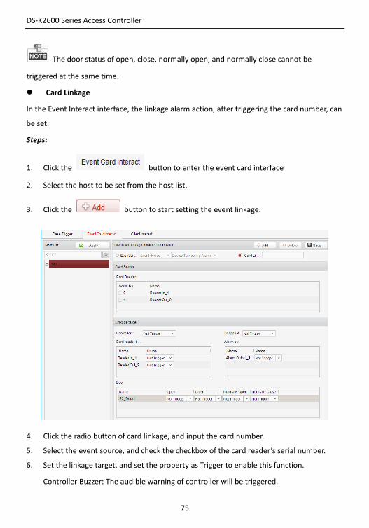
The door status of open, close, normally open, and normally close cannot be
triggered at the same time.
Card Linkage
In the Event Interact interface, the linkage alarm action, after triggering the card number, can
be set.
Steps:
1. Click the button to enter the event card interface
2. Select the host to be set from the host list.
3. Click the button to start setting the event linkage.
4. Click the radio button of card linkage, and input the card number.
5. Select the event source, and check the checkbox of the card reader’s serial number.
6. Set the linkage target, and set the property as Trigger to enable this function.
Controller Buzzer: The audible warning of controller will be triggered.
DS-K2600 Series Access Controller
76
Snapshot: The real-time capture will be triggered.
Reader Buzzer: The audible warning of card reader will be triggered.
Alarm Output: The alarm output will be triggered for notification.
Door: The door status of open, close, normally open, and normally close will be
triggered.
7. Click the button to save parameters.
8. Click the Apply button to download the updated parameters to the local memory of the
device.
The door status of open, close, normally open, and normally close cannot be
triggered at the same time.
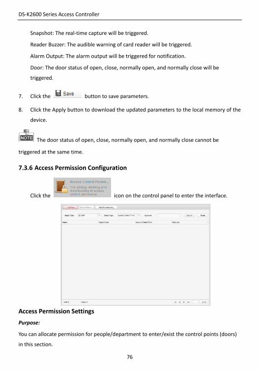
7.3.6 Access Permission Configuration
Click the icon on the control panel to enter the interface.
Access Permission Settings
Purpose:
You can allocate permission for people/department to enter/exist the control points (doors)
in this section.
DS-K2600 Series Access Controller
77
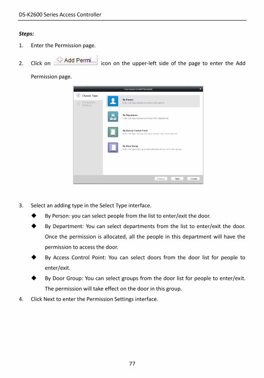
Steps:
1. Enter the Permission page.
2. Click on icon on the upper-left side of the page to enter the Add
Permission page.
3. Select an adding type in the Select Type interface.
By Person: you can select people from the list to enter/exit the door.
By Department: You can select departments from the list to enter/exit the door.
Once the permission is allocated, all the people in this department will have the
permission to access the door.
By Access Control Point: You can select doors from the door list for people to
enter/exit.
By Door Group: You can select groups from the door list for people to enter/exit.
The permission will take effect on the door in this group.
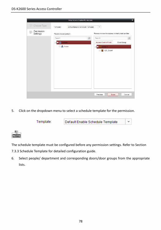
4. Click Next to enter the Permission Settings interface.
DS-K2600 Series Access Controller
78
5. Click on the dropdown menu to select a schedule template for the permission.
The schedule template must be configured before any permission settings. Refer to Section
7.3.3 Schedule Template for detailed configuration guide.
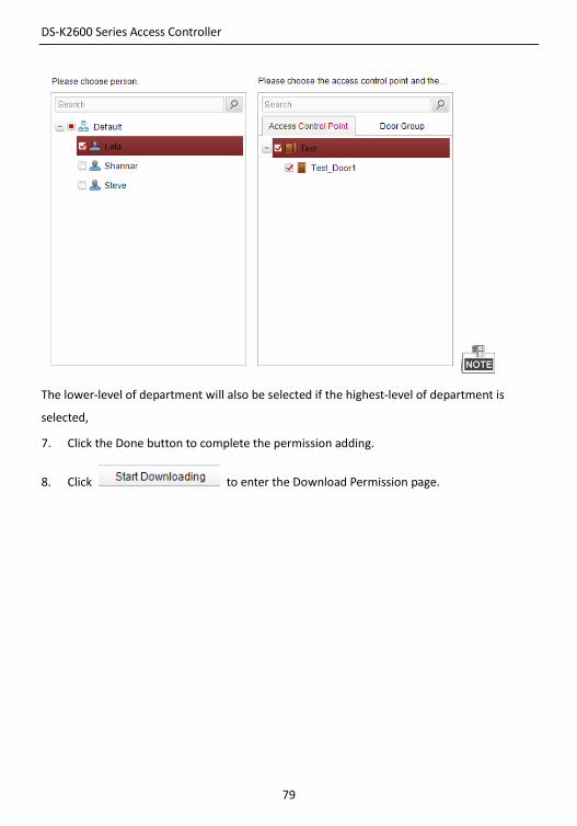
6. Select people/ department and corresponding doors/door groups from the appropriate
lists.
DS-K2600 Series Access Controller
79
The lower-level of department will also be selected if the highest-level of department is
selected,
7. Click the Done button to complete the permission adding.
8. Click to enter the Download Permission page.
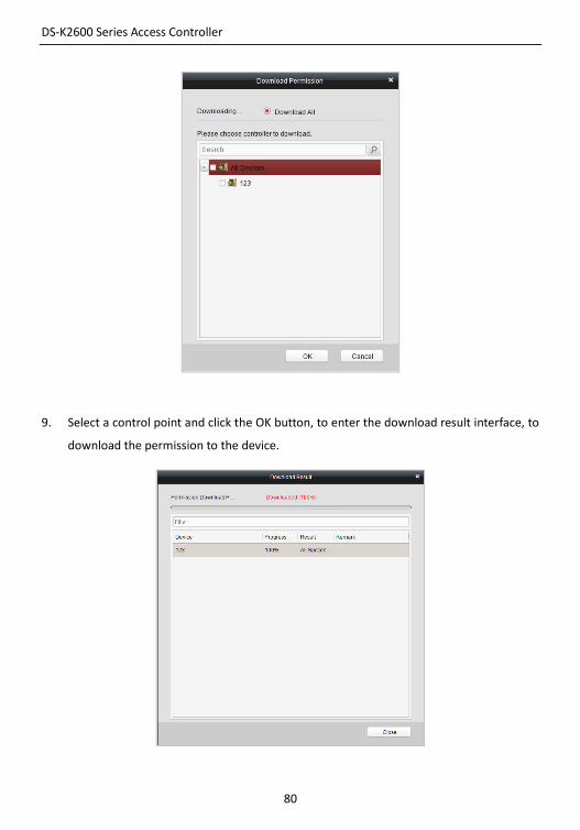
DS-K2600 Series Access Controller
80
9. Select a control point and click the OK button, to enter the download result interface, to
download the permission to the device.
DS-K2600 Series Access Controller
81
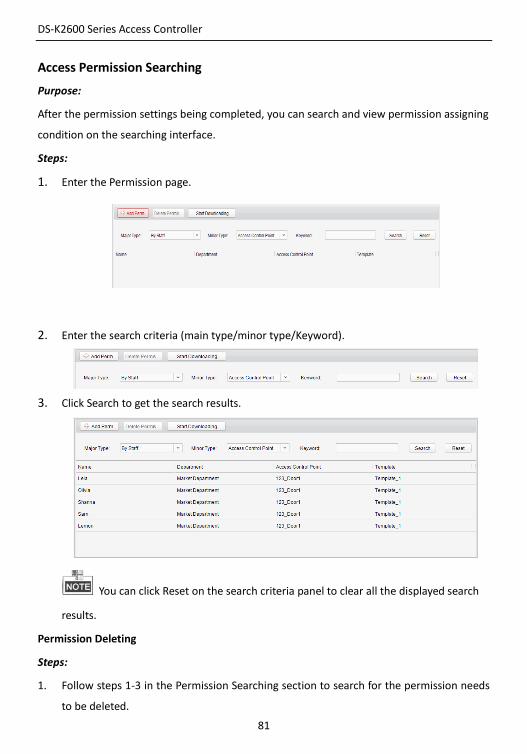
Access Permission Searching
Purpose:
After the permission settings being completed, you can search and view permission assigning
condition on the searching interface.
Steps:
1. Enter the Permission page.
2. Enter the search criteria (main type/minor type/Keyword).
3. Click Search to get the search results.
You can click Reset on the search criteria panel to clear all the displayed search
results.
Permission Deleting
Steps:
1. Follow steps 1-3 in the Permission Searching section to search for the permission needs
to be deleted.
DS-K2600 Series Access Controller
82
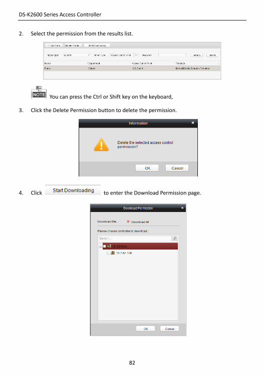
2. Select the permission from the results list.
You can press the Ctrl or Shift key on the keyboard,
3. Click the Delete Permission button to delete the permission.
4. Click to enter the Download Permission page.
DS-K2600 Series Access Controller
83
5. Select a control point and click the OK button to download the deletion operation to the
device.
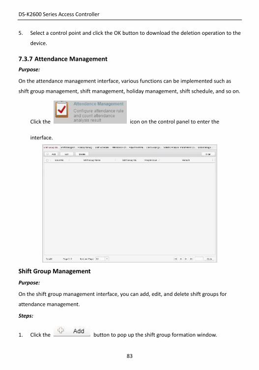
7.3.7 Attendance Management
Purpose:
On the attendance management interface, various functions can be implemented such as
shift group management, shift management, holiday management, shift schedule, and so on.
Click the icon on the control panel to enter the
interface.
Shift Group Management
Purpose:
On the shift group management interface, you can add, edit, and delete shift groups for
attendance management.
Steps:
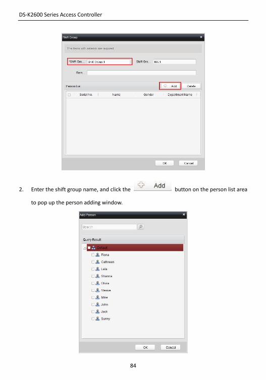
1. Click the button to pop up the shift group formation window.
DS-K2600 Series Access Controller
84
2. Enter the shift group name, and click the button on the person list area
to pop up the person adding window.
DS-K2600 Series Access Controller
85
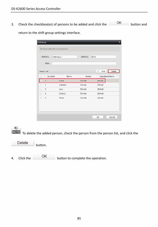
3. Check the checkbox(es) of persons to be added and click the button and
return to the shift group settings interface.
To delete the added person, check the person from the person list, and click the
button.
4. Click the button to complete the operation.
DS-K2600 Series Access Controller
86
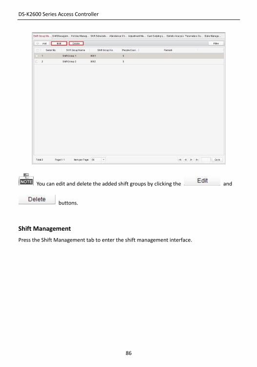
You can edit and delete the added shift groups by clicking the and
buttons.
Shift Management
Press the Shift Management tab to enter the shift management interface.
DS-K2600 Series Access Controller
87
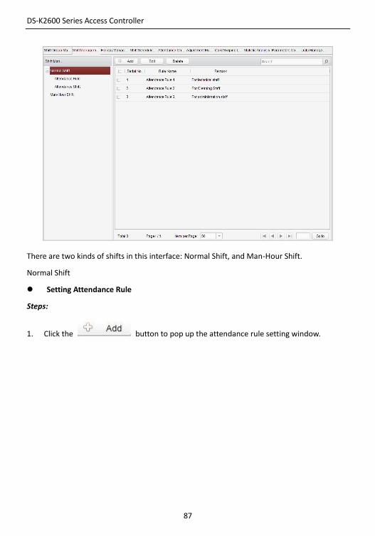
There are two kinds of shifts in this interface: Normal Shift, and Man-Hour Shift.
Normal Shift
Setting Attendance Rule
Steps:
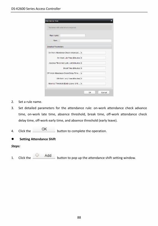
1. Click the button to pop up the attendance rule setting window.
DS-K2600 Series Access Controller
88
2. Set a rule name.
3. Set detailed parameters for the attendance rule: on-work attendance check advance
time, on-work late time, absence threshold, break time, off-work attendance check
delay time, off-work early time, and absence threshold (early leave).
4. Click the button to complete the operation.
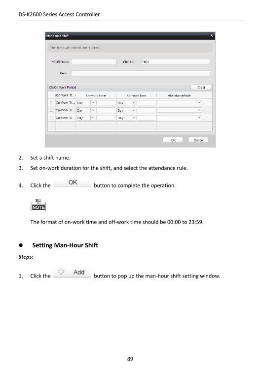
Setting Attendance Shift
Steps:
1. Click the button to pop up the attendance shift setting window.
DS-K2600 Series Access Controller
89
2. Set a shift name.
3. Set on-work duration for the shift, and select the attendance rule.
4. Click the button to complete the operation.
The format of on-work time and off-work time should be 00:00 to 23:59.
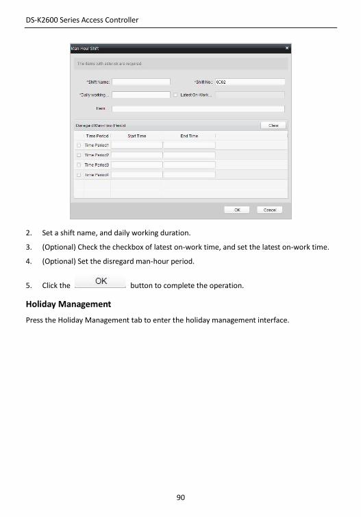
Setting Man-Hour Shift
Steps:
1. Click the button to pop up the man-hour shift setting window.
DS-K2600 Series Access Controller
90
2. Set a shift name, and daily working duration.
3. (Optional) Check the checkbox of latest on-work time, and set the latest on-work time.
4. (Optional) Set the disregard man-hour period.
5. Click the button to complete the operation.
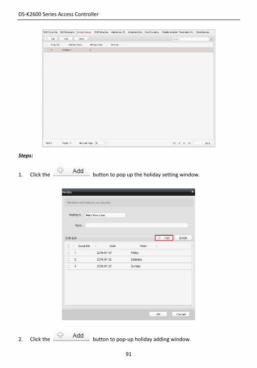
Holiday Management
Press the Holiday Management tab to enter the holiday management interface.
DS-K2600 Series Access Controller
91
Steps:
1. Click the button to pop up the holiday setting window.
2. Click the button to pop-up holiday adding window.
DS-K2600 Series Access Controller
92
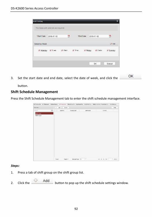
3. Set the start date and end date, select the date of week, and click the
button.
Shift Schedule Management
Press the Shift Schedule Management tab to enter the shift schedule management interface.
Steps:
1. Press a tab of shift group on the shift group list.
2. Click the button to pop up the shift schedule settings window.
DS-K2600 Series Access Controller
93
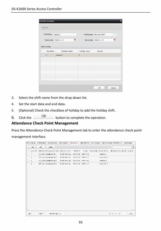
3. Select the shift name from the drop-down list.
4. Set the start data and end data.
5. (Optional) Check the checkbox of holiday to add the holiday shift.
6. Click the button to complete the operation.
Attendance Check Point Management
Press the Attendance Check Point Management tab to enter the attendance check point
management interface.
DS-K2600 Series Access Controller
94
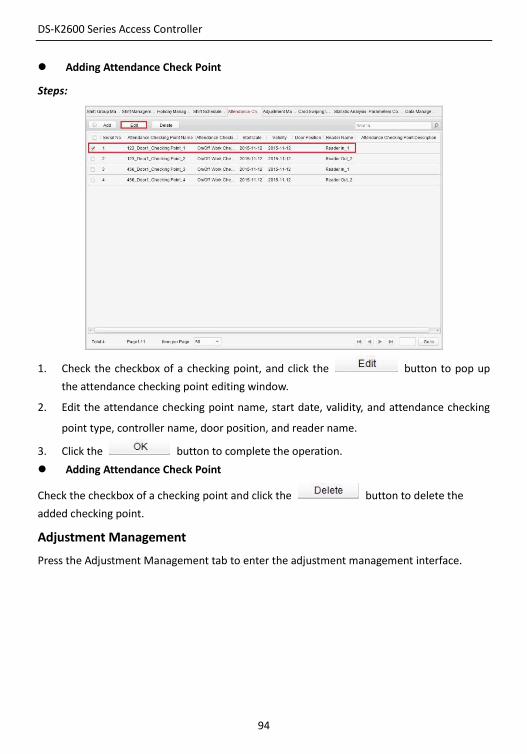
Adding Attendance Check Point
Steps:
1. Check the checkbox of a checking point, and click the button to pop up
the attendance checking point editing window.
2. Edit the attendance checking point name, start date, validity, and attendance checking
point type, controller name, door position, and reader name.
3. Click the button to complete the operation.
Adding Attendance Check Point
Check the checkbox of a checking point and click the button to delete the
added checking point.
Adjustment Management
Press the Adjustment Management tab to enter the adjustment management interface.
DS-K2600 Series Access Controller
95
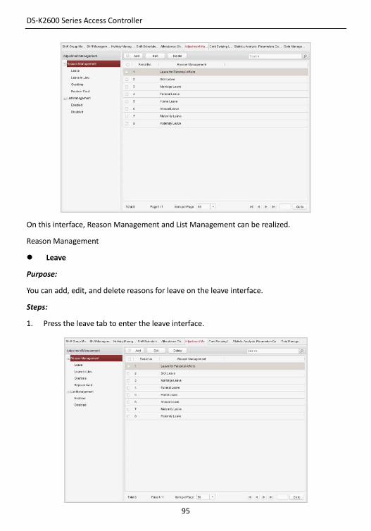
On this interface, Reason Management and List Management can be realized.
Reason Management
Leave
Purpose:
You can add, edit, and delete reasons for leave on the leave interface.
Steps:
1. Press the leave tab to enter the leave interface.
DS-K2600 Series Access Controller
96
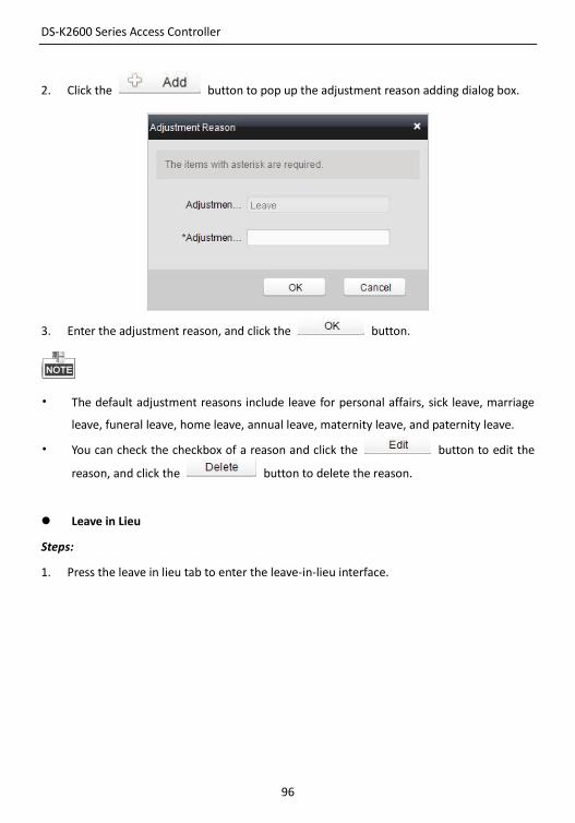
2. Click the button to pop up the adjustment reason adding dialog box.
3. Enter the adjustment reason, and click the button.
• The default adjustment reasons include leave for personal affairs, sick leave, marriage
leave, funeral leave, home leave, annual leave, maternity leave, and paternity leave.
• You can check the checkbox of a reason and click the button to edit the
reason, and click the button to delete the reason.
Leave in Lieu
Steps:
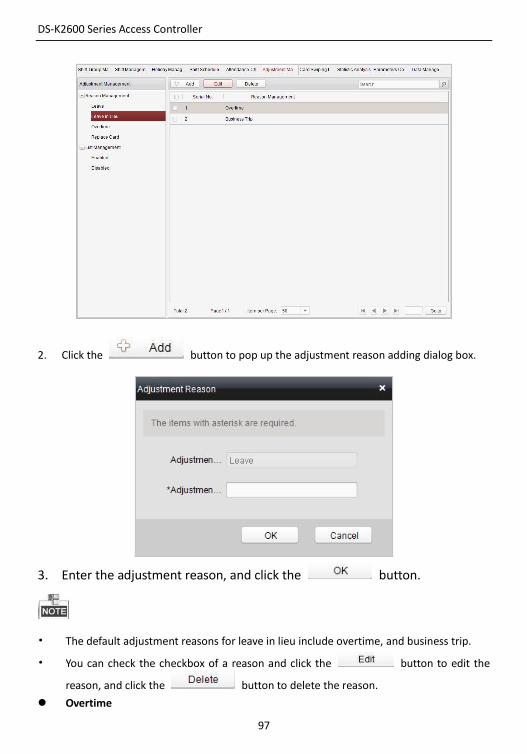
1. Press the leave in lieu tab to enter the leave-in-lieu interface.
DS-K2600 Series Access Controller
97
2. Click the button to pop up the adjustment reason adding dialog box.
3. Enter the adjustment reason, and click the button.
• The default adjustment reasons for leave in lieu include overtime, and business trip.
• You can check the checkbox of a reason and click the button to edit the
reason, and click the button to delete the reason.
Overtime
DS-K2600 Series Access Controller
98
Steps:
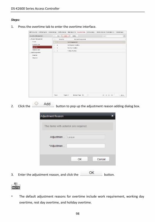
1. Press the overtime tab to enter the overtime interface.
2. Click the button to pop up the adjustment reason adding dialog box.
3. Enter the adjustment reason, and click the button.
• The default adjustment reasons for overtime include work requirement, working day
overtime, rest day overtime, and holiday overtime.
DS-K2600 Series Access Controller
99
• You can check the checkbox of a reason and click the button to edit
the reason, and click the button to delete the reason.
Replace Card
Steps:
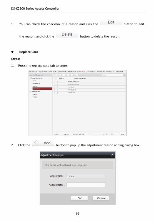
1. Press the replace card tab to enter.
2. Click the button to pop up the adjustment reason adding dialog box.
DS-K2600 Series Access Controller
100
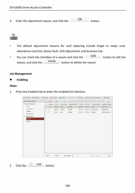
3. Enter the adjustment reason, and click the button.
• The default adjustment reasons for card replacing include forget to swipe card,
attendance card lost, device fault, shift adjustment, and business trip.
• You can check the checkbox of a reason and click the button to edit the
reason, and click the button to delete the reason.
List Management
Enabling
Steps:
1. Press the Enabled tab to enter the enabled list interface.
2. Click the button.
DS-K2600 Series Access Controller
101
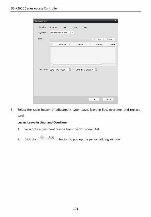
3. Select the radio button of adjustment type: leave, leave in lieu, overtime, and replace
card.
Leave, Leave in Lieu, and Overtime
1) Select the adjustment reason from the drop-down list.
2) Click the button to pop up the person adding window.
DS-K2600 Series Access Controller
102
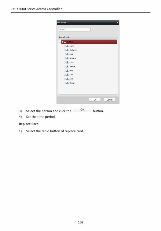
3) Select the person and click the button.
4) Set the time period.
Replace Card
1) Select the radio button of replace card.
DS-K2600 Series Access Controller
103
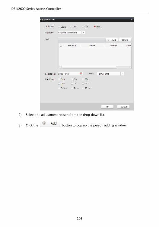
2) Select the adjustment reason from the drop-down list.
3) Click the button to pop up the person adding window.
DS-K2600 Series Access Controller
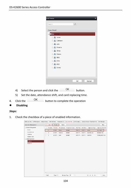
104
4) Select the person and click the button.
5) Set the date, attendance shift, and card replacing time.
4. Click the button to complete the operation
Disabling
Steps:
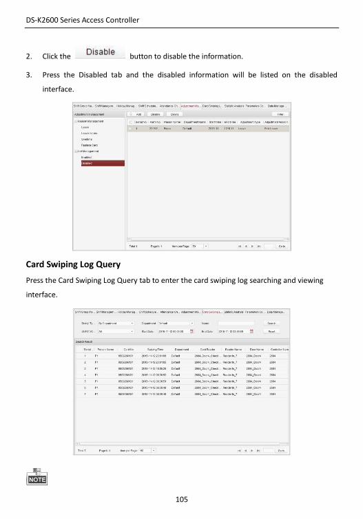
1. Check the checkbox of a piece of enabled information.
DS-K2600 Series Access Controller
105
2. Click the button to disable the information.
3. Press the Disabled tab and the disabled information will be listed on the disabled
interface.
Card Swiping Log Query
Press the Card Swiping Log Query tab to enter the card swiping log searching and viewing
interface.
DS-K2600 Series Access Controller
106
• You can search the card swiping log by two query types: By Shift Group, and By
Department.
• You can search the card swiping log by group name.
• You can search the card swiping log by start date and end date.
• You can restrict the query scope: All, First, or Last.
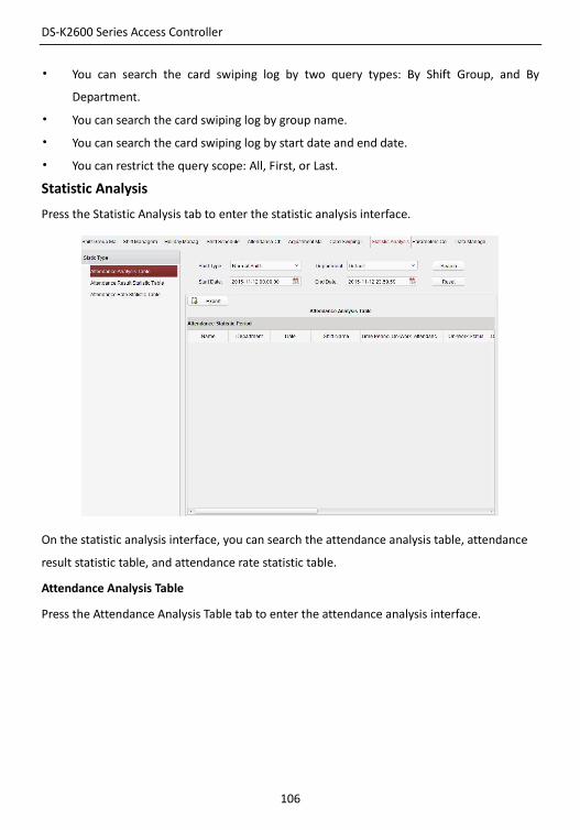
Statistic Analysis
Press the Statistic Analysis tab to enter the statistic analysis interface.
On the statistic analysis interface, you can search the attendance analysis table, attendance
result statistic table, and attendance rate statistic table.
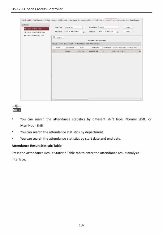
Attendance Analysis Table
Press the Attendance Analysis Table tab to enter the attendance analysis interface.
DS-K2600 Series Access Controller
107
• You can search the attendance statistics by different shift type: Normal Shift, or
Man-Hour Shift.
• You can search the attendance statistics by department.
• You can search the attendance statistics by start date and end date.
Attendance Result Statistic Table
Press the Attendance Result Statistic Table tab to enter the attendance result analysis
interface.
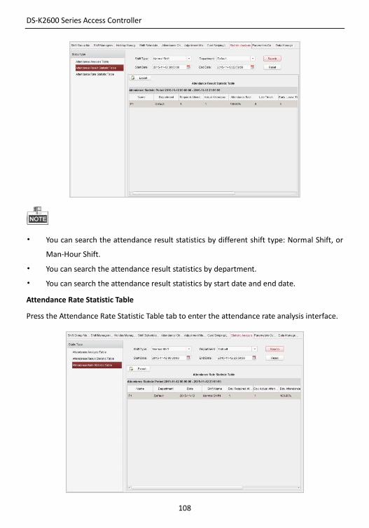
DS-K2600 Series Access Controller
108
• You can search the attendance result statistics by different shift type: Normal Shift, or
Man-Hour Shift.
• You can search the attendance result statistics by department.
• You can search the attendance result statistics by start date and end date.
Attendance Rate Statistic Table
Press the Attendance Rate Statistic Table tab to enter the attendance rate analysis interface.
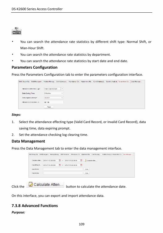
DS-K2600 Series Access Controller
109
• You can search the attendance rate statistics by different shift type: Normal Shift, or
Man-Hour Shift.
• You can search the attendance rate statistics by department.
• You can search the attendance rate statistics by start date and end date.
Parameters Configuration
Press the Parameters Configuration tab to enter the parameters configuration interface.
Steps:
1. Select the attendance effecting type (Valid Card Record, or Invalid Card Record), data
saving time, data expiring prompt.
2. Set the attendance checking log clearing time.
Data Management
Press the Data Management tab to enter the data management interface.
Click the button to calculate the attendance date.
On this interface, you can export and import attendance data.
7.3.8 Advanced Functions
Purpose:
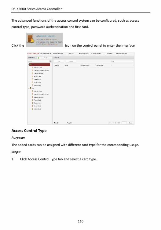
DS-K2600 Series Access Controller
110
The advanced functions of the access control system can be configured, such as access
control type, password authentication and first card.
Click the icon on the control panel to enter the interface.
Access Control Type
Purpose:
The added cards can be assigned with different card type for the corresponding usage.
Steps:
1. Click Access Control Type tab and select a card type.
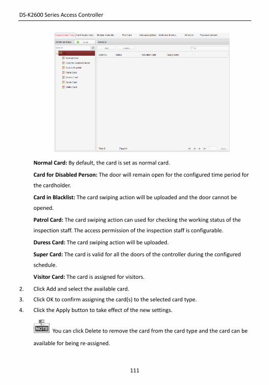
DS-K2600 Series Access Controller
111
Normal Card: By default, the card is set as normal card.
Card for Disabled Person: The door will remain open for the configured time period for
the cardholder.
Card in Blacklist: The card swiping action will be uploaded and the door cannot be
opened.
Patrol Card: The card swiping action can used for checking the working status of the
inspection staff. The access permission of the inspection staff is configurable.
Duress Card: The card swiping action will be uploaded.
Super Card: The card is valid for all the doors of the controller during the configured
schedule.
Visitor Card: The card is assigned for visitors.
2. Click Add and select the available card.
3. Click OK to confirm assigning the card(s) to the selected card type.
4. Click the Apply button to take effect of the new settings.
You can click Delete to remove the card from the card type and the card can be
available for being re-assigned.
DS-K2600 Series Access Controller
112
Card Reader Authentication
Purpose:
You can only open the door by both swiping card and entering the password during the set
time periods.
For this authentication mode, the card swiping operation cannot be replaced by
entering the card No..
For password settings, please refer to Section 16.2.3 Normal Card.
Steps:
1. Click Card Reader Authentication tab and select a card reader.
2. Select a card reader authentication type from the dropdown list.
Fingerprint: The door can open by only inputting the fingerprint.
Swipe Card: The door can open by only swiping the card.
Fingerprint/Swipe Card: The door can open by inputting the fingerprint or swiping the
card.
Swipe Card/Password: The door can open by inputting the password or swiping the
card.
Fingerprint Password: The door can open by both inputting the password and
inputting the fingerprint.
Swipe Card Password: The door can open by both inputting the password and swiping
the card.
Fingerprint Swipe Card: The door can open by both inputting the fingerprint and
swiping the card.
Fingerprint Swipe Card Password: The door can open by inputting the fingerprint,
inputting the password, and swiping the card.
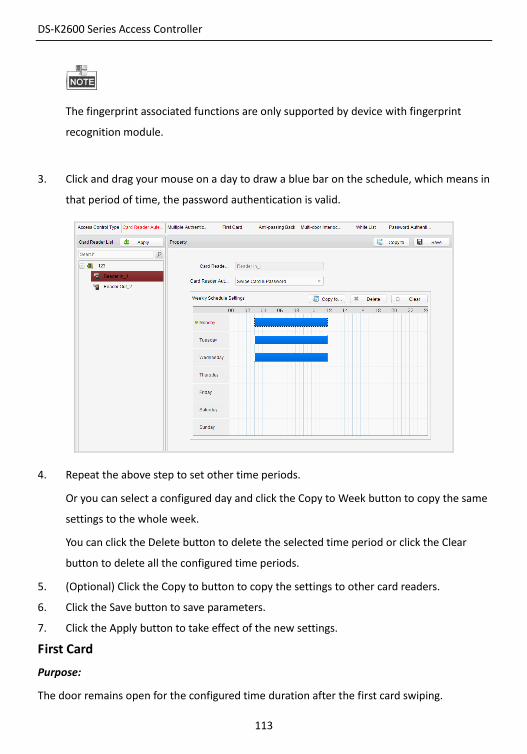
DS-K2600 Series Access Controller
113
The fingerprint associated functions are only supported by device with fingerprint
recognition module.
3. Click and drag your mouse on a day to draw a blue bar on the schedule, which means in
that period of time, the password authentication is valid.
4. Repeat the above step to set other time periods.
Or you can select a configured day and click the Copy to Week button to copy the same
settings to the whole week.
You can click the Delete button to delete the selected time period or click the Clear
button to delete all the configured time periods.
5. (Optional) Click the Copy to button to copy the settings to other card readers.
6. Click the Save button to save parameters.
7. Click the Apply button to take effect of the new settings.
First Card
Purpose:
The door remains open for the configured time duration after the first card swiping.
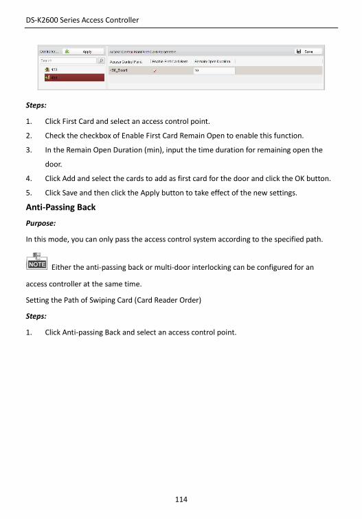
DS-K2600 Series Access Controller
114
Steps:
1. Click First Card and select an access control point.
2. Check the checkbox of Enable First Card Remain Open to enable this function.
3. In the Remain Open Duration (min), input the time duration for remaining open the
door.
4. Click Add and select the cards to add as first card for the door and click the OK button.
5. Click Save and then click the Apply button to take effect of the new settings.
Anti-Passing Back
Purpose:
In this mode, you can only pass the access control system according to the specified path.
Either the anti-passing back or multi-door interlocking can be configured for an
access controller at the same time.
Setting the Path of Swiping Card (Card Reader Order)
Steps:
1. Click Anti-passing Back and select an access control point.
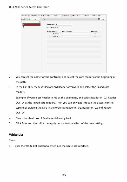
DS-K2600 Series Access Controller
115
2. You can set the name for the controller and select the card reader as the beginning of
the path.
3. In the list, click the text filed of Card Reader Afterward and select the linked card
readers.
Example: If you select Reader In_01 as the beginning, and select Reader In_02, Reader
Out_04 as the linked card readers. Then you can only get through the access control
system by swiping the card in the order as Reader In_01, Reader In_02 and Reader
Out_04.
4. Check the checkbox of Enable Anti-Passing back.
5. Click Save and then click the Apply button to take effect of the new settings.
White List
Steps:
1. Click the White List button to enter into the white list interface.
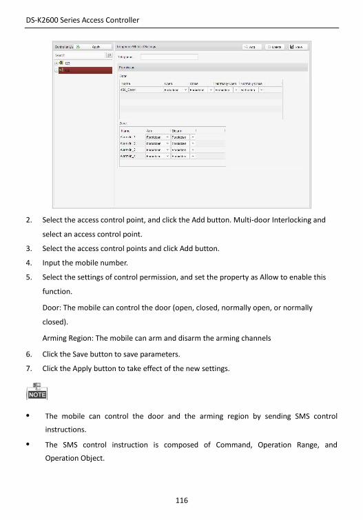
DS-K2600 Series Access Controller
116
2. Select the access control point, and click the Add button. Multi-door Interlocking and
select an access control point.
3. Select the access control points and click Add button.
4. Input the mobile number.
5. Select the settings of control permission, and set the property as Allow to enable this
function.
Door: The mobile can control the door (open, closed, normally open, or normally
closed).
Arming Region: The mobile can arm and disarm the arming channels
6. Click the Save button to save parameters.
7. Click the Apply button to take effect of the new settings.
• The mobile can control the door and the arming region by sending SMS control
instructions.
• The SMS control instruction is composed of Command, Operation Range, and
Operation Object.
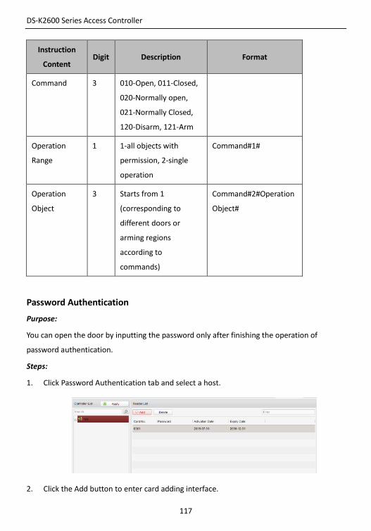
DS-K2600 Series Access Controller
117
Instruction
Content Digit Description Format
Command 3 010-Open, 011-Closed,
020-Normally open,
021-Normally Closed,
120-Disarm, 121-Arm
Operation
Range
1 1-all objects with
permission, 2-single
operation
Command#1#
Operation
Object
3 Starts from 1
(corresponding to
different doors or
arming regions
according to
commands)
Command#2#Operation
Object#
Password Authentication
Purpose:
You can open the door by inputting the password only after finishing the operation of
password authentication.
Steps:
1. Click Password Authentication tab and select a host.
2. Click the Add button to enter card adding interface.
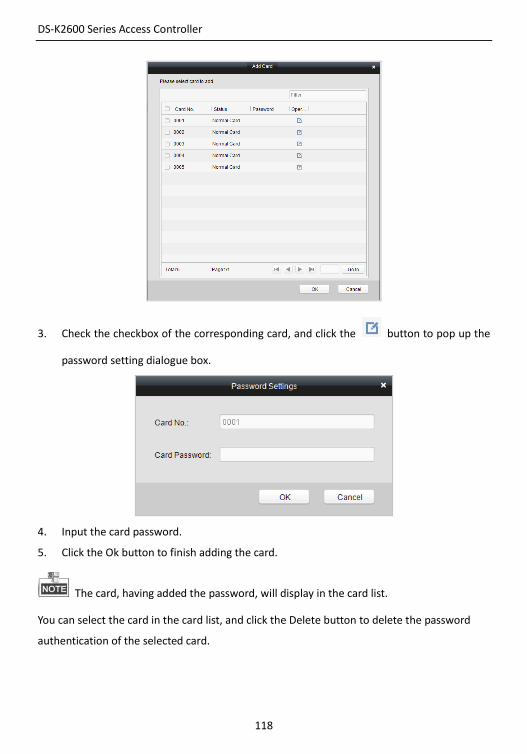
DS-K2600 Series Access Controller
118
3. Check the checkbox of the corresponding card, and click the button to pop up the
password setting dialogue box.
4. Input the card password.
5. Click the Ok button to finish adding the card.
The card, having added the password, will display in the card list.
You can select the card in the card list, and click the Delete button to delete the password
authentication of the selected card.
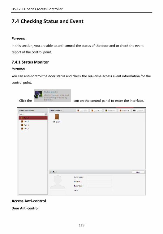
DS-K2600 Series Access Controller
119
7.4 Checking Status and Event
Purpose:
In this section, you are able to anti-control the status of the door and to check the event
report of the control point.
7.4.1 Status Monitor
Purpose:
You can anti-control the door status and check the real-time access event information for the
control point.
Click the icon on the control panel to enter the interface.
Access Anti-control
Door Anti-control
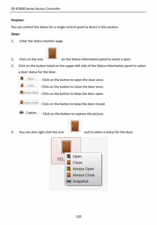
DS-K2600 Series Access Controller
120
Purpose:
You can control the status for a single control point (a door) in this section.
Steps:
1. Enter the status monitor page.
2. Click on the icon on the Status Information panel to select a door.
3. Click on the button listed on the upper-left side of the Status Information panel to select
a door status for the door.
: Click on the button to open the door once.
: Click on the button to close the door once.
: Click on the button to keep the door open.
: Click on the button to keep the door closed.
: Click on the button to capture the picture.
4. You can also right click the icon and to select a status for the door.
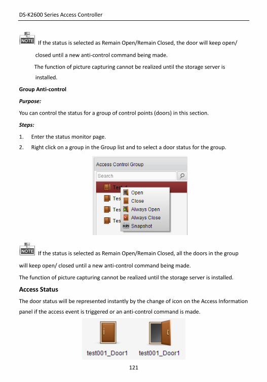
DS-K2600 Series Access Controller
121
If the status is selected as Remain Open/Remain Closed, the door will keep open/
closed until a new anti-control command being made.
The function of picture capturing cannot be realized until the storage server is
installed.
Group Anti-control
Purpose:
You can control the status for a group of control points (doors) in this section.
Steps:
1. Enter the status monitor page.
2. Right click on a group in the Group list and to select a door status for the group.
If the status is selected as Remain Open/Remain Closed, all the doors in the group
will keep open/ closed until a new anti-control command being made.
The function of picture capturing cannot be realized until the storage server is installed.
Access Status
The door status will be represented instantly by the change of icon on the Access Information
panel if the access event is triggered or an anti-control command is made.
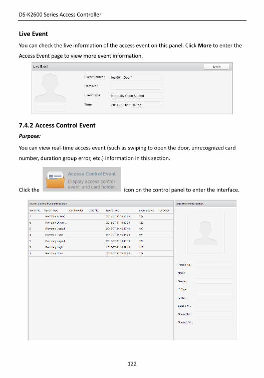
DS-K2600 Series Access Controller
122
Live Event
You can check the live information of the access event on this panel. Click More to enter the
Access Event page to view more event information.
7.4.2 Access Control Event
Purpose:
You can view real-time access event (such as swiping to open the door, unrecognized card
number, duration group error, etc.) information in this section.
Click the icon on the control panel to enter the interface.
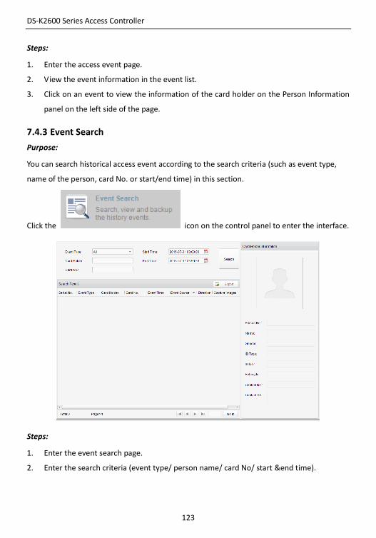
DS-K2600 Series Access Controller
123
Steps:
1. Enter the access event page.
2. View the event information in the event list.
3. Click on an event to view the information of the card holder on the Person Information
panel on the left side of the page.
7.4.3 Event Search
Purpose:
You can search historical access event according to the search criteria (such as event type,
name of the person, card No. or start/end time) in this section.
Click the icon on the control panel to enter the interface.
Steps:
1. Enter the event search page.
2. Enter the search criteria (event type/ person name/ card No/ start &end time).
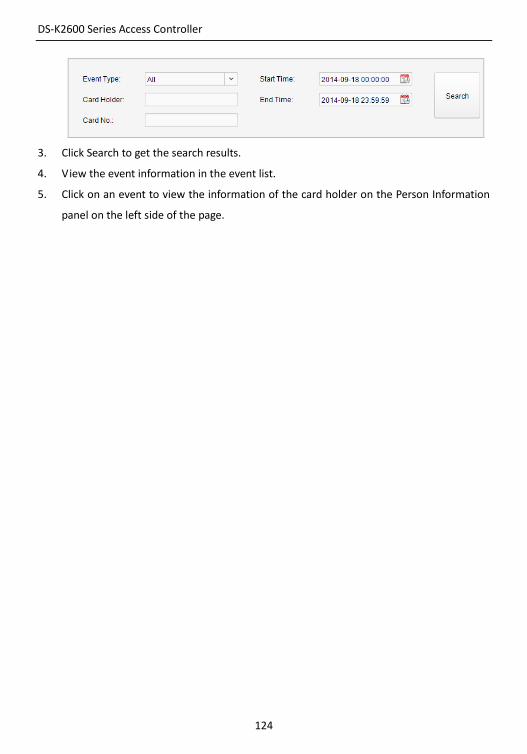
DS-K2600 Series Access Controller
124
3. Click Search to get the search results.
4. View the event information in the event list.
5. Click on an event to view the information of the card holder on the Person Information
panel on the left side of the page.
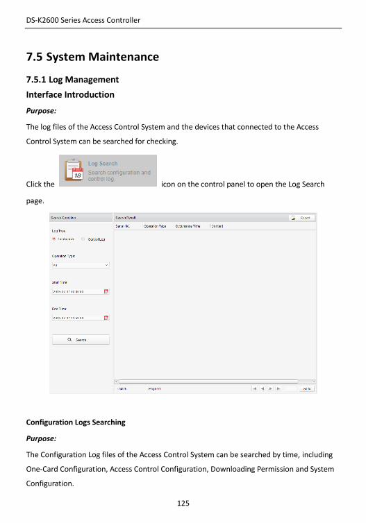
DS-K2600 Series Access Controller
125
7.5 System Maintenance
7.5.1 Log Management
Interface Introduction
Purpose:
The log files of the Access Control System and the devices that connected to the Access
Control System can be searched for checking.
Click the icon on the control panel to open the Log Search
page.
Configuration Logs Searching
Purpose:
The Configuration Log files of the Access Control System can be searched by time, including
One-Card Configuration, Access Control Configuration, Downloading Permission and System
Configuration.
DS-K2600 Series Access Controller
126
Steps:
1. Open the Log Search page.
2. Select the radio button of Configuration Logs.
3. Select the Operation Type of log files.
4. Click the icon to specify the start time and end time.
5. Click Search. The matched log files will display on the list.
You can check the operation time, log type and other information of the logs.
Please narrow the search condition if there are too many log files.
Control Logs Searching
Purpose:
The Control Log files of the Access Control System can be searched by time, including Access
Control and Log Search.
Steps:
1. Open the Log Search page.
2. Select the radio button of Control Logs.
3. Select the Operation Type of log files.
4. Click the icon to specify the start time and end time.
5. Click Search. The matched log files will display on the list.
You can check the operation time, log type and other information of the logs.
Please narrow the search condition if there are too many log files.
Searching Configuration Log
Searching One-card Configuration Logs
Purpose:
The One-card Configuration Log files include departments, persons and cards log files.
One-card Configuration of the Access Control System can be operated as adding, modifying
and deleting logs.
Steps:
DS-K2600 Series Access Controller
127
1. Open the Log Search page.
2. Select the radio button of Configuration Logs.
3. Select the operation type as One-card Configuration.
4. Click the icon to specify the start time and end time.
5. Click Search. The matched log files will display on the list.
You can check the operation time, log type and other information of the logs.
Please narrow the search condition if there are too many log files.
Searching Access Control Configuration Logs
Purpose:
The Access Control Configuration Log files include Access Control devices log files. Access
Control Configuration of the Access Control System can be operated as adding, modifying
and deleting door groups or doors and access control device permission operations.
Steps:
1. Open the Log Search page.
2. Select the radio button of Configuration Logs.
3. Select the operation type as Access Control Configuration.
4. Click the icon to specify the start time and end time.
5. Click Search. The matched log files will display on the list.
You can check the operation time, log type and other information of the logs.
Please narrow the search condition if there are too many log files.
Searching Downloading Permission Logs
Purpose:
The Downloading Permission Log files include downloading permission log files, and no
record for downloading permission failure log files.
Steps:
1. Open the Log Search page.
DS-K2600 Series Access Controller
128
2. Select the radio button of Configuration Logs.
3. Select the operation type as Downloading Permission.
4. Click the icon to specify the start time and end time.
5. Click Search. The matched log files will display on the list.
You can check the operation time, log type and other information of the logs.
Please narrow the search condition if there are too many log files.
Searching System Configuration Logs
Purpose:
The System Configuration Log files of the Access Control System can be searched as system
configuration interface log files.
Steps:
1. Open the Log Search page.
2. Select the radio button of Configuration Logs.
3. Select the operation type as System Configuration Logs.
4. Click the icon to specify the start time and end time.
5. Click Search. The matched log files will display on the list.
You can check the operation time, log type and other information of the logs.
Please narrow the search condition if there are too many log files.
Searching Control Log
Searching Access Control Logs
Purpose:
The Access Control Log files of the Access Control System include door groups and doors
access control logs and door on/off control log files.
Steps:
1. Open the Log Search page.
2. Select the radio button of Control Logs.
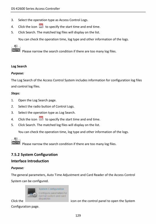
DS-K2600 Series Access Controller
129
3. Select the operation type as Access Control Logs.
4. Click the icon to specify the start time and end time.
5. Click Search. The matched log files will display on the list.
You can check the operation time, log type and other information of the logs.
Please narrow the search condition if there are too many log files.
Log Search
Purpose:
The Log Search of the Access Control System includes information for configuration log files
and control log files.
Steps:
1. Open the Log Search page.
2. Select the radio button of Control Logs.
3. Select the operation type as Log Search.
4. Click the icon to specify the start time and end time.
5. Click Search. The matched log files will display on the list.
You can check the operation time, log type and other information of the logs.
Please narrow the search condition if there are too many log files.
7.5.2 System Configuration
Interface Introduction
Purpose:
The general parameters, Auto Time Adjustment and Card Reader of the Access Control
System can be configured.
Click the icon on the control panel to open the System
Configuration page.
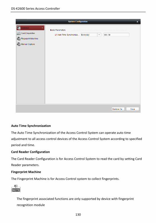
DS-K2600 Series Access Controller
130
Auto Time Synchronization
The Auto Time Synchronization of the Access Control System can operate auto time
adjustment to all access control devices of the Access Control System according to specified
period and time.
Card Reader Configuration
The Card Reader Configuration is for Access Control System to read the card by setting Card
Reader parameters.
Fingerprint Machine
The Fingerprint Machine is for Access Control system to collect fingerprints.
The fingerprint associated functions are only supported by device with fingerprint
recognition module
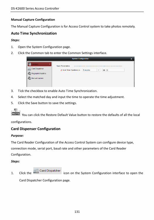
DS-K2600 Series Access Controller
131
Manual Capture Configuration
The Manual Capture Configuration is for Access Control system to take photos remotely.
Auto Time Synchronization
Steps:
1. Open the System Configuration page.
2. Click the Common tab to enter the Common Settings interface.
3. Tick the checkbox to enable Auto Time Synchronization.
4. Select the matched day and input the time to operate the time adjustment.
5. Click the Save button to save the settings.
You can click the Restore Default Value button to restore the defaults of all the local
configurations.
Card Dispenser Configuration
Purpose:
The Card Reader Configuration of the Access Control System can configure device type,
connection mode, serial port, baud rate and other parameters of the Card Reader
Configuration.
Steps:
1. Click the icon on the System Configuration interface to open the
Card Dispatcher Configuration page.
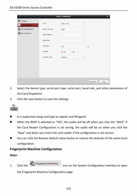
DS-K2600 Series Access Controller
132
2. Select the device type, serial port type, serial port, baud rate, and other parameters of
the Card Dispatcher.
3. Click the save button to save the settings.
It is supported using card type as regular and Wiegand.
When the BEEP is selected as “YES”, the audio will be off when you click the “SAVE” if
the Card Reader Configuration is set wrong; the audio will be on when you click the
“Save” and when you insert the card reader if the configuration is set correct.
You can click the Restore Default Value button to restore the defaults of the entire local
configuration.
Fingerprint Machine Configuration
Steps:
1. Click the icon on the System Configuration interface to open
the Fingerprint Machine Configuration page.
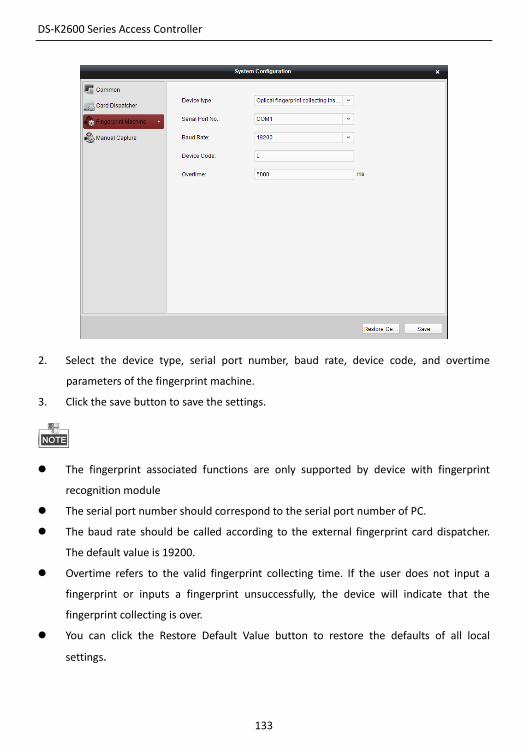
DS-K2600 Series Access Controller
133
2. Select the device type, serial port number, baud rate, device code, and overtime
parameters of the fingerprint machine.
3. Click the save button to save the settings.
The fingerprint associated functions are only supported by device with fingerprint
recognition module
The serial port number should correspond to the serial port number of PC.
The baud rate should be called according to the external fingerprint card dispatcher.
The default value is 19200.
Overtime refers to the valid fingerprint collecting time. If the user does not input a
fingerprint or inputs a fingerprint unsuccessfully, the device will indicate that the
fingerprint collecting is over.
You can click the Restore Default Value button to restore the defaults of all local
settings.
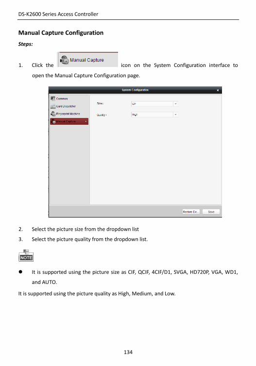
DS-K2600 Series Access Controller
134
Manual Capture Configuration
Steps:
1. Click the icon on the System Configuration interface to
open the Manual Capture Configuration page.
2. Select the picture size from the dropdown list
3. Select the picture quality from the dropdown list.
It is supported using the picture size as CIF, QCIF, 4CIF/D1, SVGA, HD720P, VGA, WD1,
and AUTO.
It is supported using the picture quality as High, Medium, and Low.

DS-K2600 Series Access Controller
135