DRYLOCK II™ A7 RETROFIT - Wilfley
23
7350 E. A2551 rev B Insta Progress Place DRY allation, • Englewood, CO YLOC Operat O USA 80111 • T C CK II™ ion, Mai VISIT WWW.WI Toll Free: 800.52 C E N T RI F U G A L P U M P S ™ A7 intenanc T US AT LFLEY.C 25.9930 • Phone: RETR ce and S T COM : 303.779.1777 • ROFIT Storage Fax: 303.779.12 T Manual 277
Transcript of DRYLOCK II™ A7 RETROFIT - Wilfley

7350 E. A2551 rev B
Insta
Progress Place
DRYallation,
• Englewood, CO
YLOC Operat
O USA 80111 • T
C
CK II™ion, Mai
VISIT
WWW.WI
Toll Free: 800.52
CENTRIFUGAL
P U M P S
™ A7 intenanc
T US AT
LFLEY.C
25.9930 • Phone:
RETRce and S
T
COM
: 303.779.1777 •
ROFITStorage
Fax: 303.779.12
T Manual
277

7350 E. Progress Place • Englewood, CO USA 80111 • Toll Free: 800.525.9930 • Phone: 303.779.1777 • Fax: 303.779.1277 A2551 rev B
CENTRIFUGAL
P U M P S
TABLE OF CONTENTS
FOREWORD ..................................................................................................................................................... 1 1.0 INTRODUCTION ......................................................................................................................................... 2 2.0 SAFETY CONSIDERATIONS ..................................................................................................................... 2 2.1 SAFETY TIPS .............................................................................................................................................. 3
Apparel ...................................................................................................................................................... 3 Maintenance .............................................................................................................................................. 3
3.0 A7 WITH DRYLOCK II™ SEAL DISASSEMBLY & REASSEMBLY ........................................................... 4 3.1 DISASSEMBLY ............................................................................................................................................ 5 3.2 CLEANING/INSPECTION............................................................................................................................ 5 3.3 DRYLOCK II™ ASSEMBLY ......................................................................................................................... 8
DryLock II™ Seal Clearance Adjustment Procedures .............................. Error! Bookmark not defined. Impeller Clearance .................................................................................................................................. 16 Standard A7 Pump .................................................................................................................................. 16 Dial Indicator Procedures ........................................................................................................................ 16 Feeler Gauge Procedures ....................................................................................................................... 16
4.0 ORDERING PARTS .................................................................................................................................. 19 5.0 SPECIAL SERVICE ................................................................................................................................... 19
FIGURES
Figure 1 - A7 PUMP ............................................................................................................................................ 4 Figure 2 - DryLock II™ Style A1 For A7 Pump ................................................................................................... 6 Figure 3 - DryLock II™ Style A2 For A7 Pump ................................................................................................... 7 Figure 4 – A7 DryLock II™ Ball Assembly .......................................................................................................... 8 Figure 5 – A7 Rotating DryLock II™ Assembly Step 1 ....................................................................................... 9 Figure 6 – A7 Rotating DryLock II™ Assembly, Step 2 .................................................................................... 10 Figure 7 – A7 Stationary DryLock II™ Assembly Step 1 .................................................................................. 11 Figure 8 – A7 Stationary DryLock II™ Assembly Step 2 – Varilip Configuration ............................................. 12 Figure 9 – A7 Stationary DryLock II™ Assembly Step 2 – Wiper Seal Configuration ...................................... 12 Figure 10 – A7 Complete DryLock II™ Assembly ............................................................................................ 13 Figure 11 – A7 Complete Pump Assembly ....................................................................................................... 14 Figure 12 – Flush Configuration ....................................................................................................................... 15 Figure 13 – Dial Indicator Method (Preferred Method) ..................................................................................... 16 Figure 14 – Feeler Gauge Method ................................................................................................................... 16 Figure 15 – Shaft Wrench Drawing .................................................................................................................. 20
TABLES
Table 1 – Casing and Impeller Clearances ...................................................................................................... 16 Table 2 – A7 Nominal Shaft Diameters ............................................................................................................ 20 Table 3 – A7 Bolt Torque Values ...................................................................................................................... 21
A2551 rev B 1
CENTRIFUGAL
P U M P S
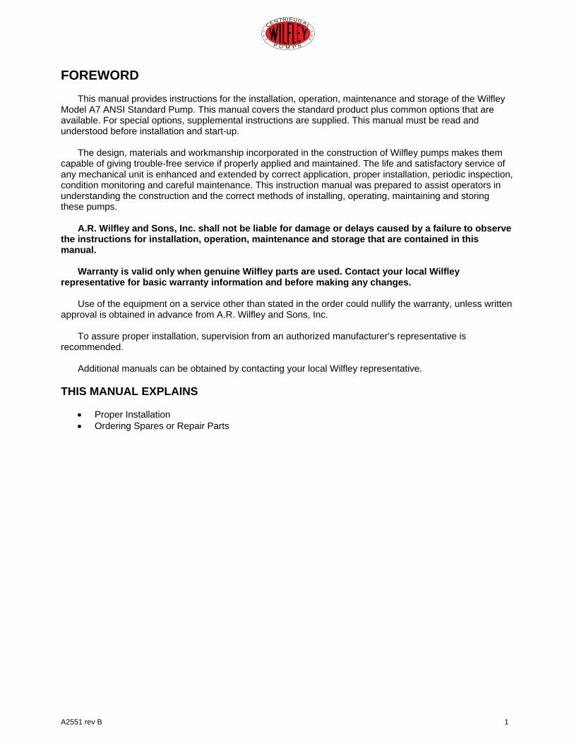
FOREWORD
This manual provides instructions for the installation, operation, maintenance and storage of the Wilfley Model A7 ANSI Standard Pump. This manual covers the standard product plus common options that are available. For special options, supplemental instructions are supplied. This manual must be read and understood before installation and start-up.
The design, materials and workmanship incorporated in the construction of Wilfley pumps makes them
capable of giving trouble-free service if properly applied and maintained. The life and satisfactory service of any mechanical unit is enhanced and extended by correct application, proper installation, periodic inspection, condition monitoring and careful maintenance. This instruction manual was prepared to assist operators in understanding the construction and the correct methods of installing, operating, maintaining and storing these pumps.
A.R. Wilfley and Sons, Inc. shall not be liable for damage or delays caused by a failure to observe
the instructions for installation, operation, maintenance and storage that are contained in this manual.
Warranty is valid only when genuine Wilfley parts are used. Contact your local Wilfley
representative for basic warranty information and before making any changes. Use of the equipment on a service other than stated in the order could nullify the warranty, unless written
approval is obtained in advance from A.R. Wilfley and Sons, Inc. To assure proper installation, supervision from an authorized manufacturer’s representative is
recommended. Additional manuals can be obtained by contacting your local Wilfley representative.
THIS MANUAL EXPLAINS
• Proper Installation • Ordering Spares or Repair Parts
2 A2551 rev B
CENTRIFUGAL
P U M P S
1.0 INTRODUCTION This manual contains instructions and guidelines for the installation, operation, maintenance and storage of the Wilfley A7 ANSI Standard Pump. There are many factors affecting the successful installation, operation and maintenance of a pump. From one pump to the next there is typically significant variation in these factors. This makes it impossible to create a bulletin that covers all situations. Therefore, the information contained herein is meant to serve only as a general guideline. If detailed questions or problems arise, contact the Wilfley Sales Office or authorized Distributor/Representative. It is extremely important that this entire manual be read prior to installation or start-up of the pump. This is important for safety, for proper performance of the pump and for maximum Mean Time between Planned Maintenance (MTBPM). 2.0 SAFETY CONSIDERATIONS Like all machinery, centrifugal pumps can be dangerous if used improperly. Any of the following misuses may result in a pump that does not function properly. A pump that does not function properly may be a hazard and could cause damage or injury. For maximum safety and reliability, use only factory-supplied parts and closely follow all maintenance and operating recommendations and instructions. Do not change the pumping conditions or installations of a Wilfley pump without consulting A.R. Wilfley and Sons, Inc. first to ascertain if the pump is capable of handling the new conditions and/or fluid. It is not possible to list all the conceivable misuses. Therefore, the following list is not meant to be complete and is provided only as a guide of the types of misuse that can damage a pump and cause injury. The list will also give a good idea of the kinds of misuses that will void any and all warranties.
1. Do not run a pump with the discharge valve closed or below minimum rated flow.
2. Do not run a pump in the reverse direction.
3. Do not start a pump that is “wind-milling” in the reserve direction due to fluid flowing back down the discharge pipe.
4. Do not continue to operate a pump when
there are indications that something is rubbing, binding or knocking.
5. Do not continue to run a pump that gives an
indication of overheating. 6. Do not operate a pump with the coupling
guard removed. Make sure the guard fits snugly around the coupling so there are no openings.
7. Do not operate a pump that is excessively
vibrating, surging or making abnormal noise.
8. Do not work on a pump unless the drive
system is locked out and the pump is disconnected from the drive system.
9. Do not connect the pump to the drive
system without first checking to see that the drive system is running in the correct direction.
10. Do not rely on the factory’s alignment of the
pump and the drive system. Alignment may have changed during shipment.
11. Do not put a cold liquid in or on a hot pump
or a hot liquid in or on a cold pump. 12. Do not hit a pump with any object. 13. Do not use worn or faulty parts. 14. Do not stick hands, arms, legs or any other
object into the discharge, suction or any other opening of a pump.
15. Do not weld attachments to the pump. 16. Do not apply external heat to the pump. 17. Do not lift the pump by its case only. 18. Do not examine a pump without using
proper eye and face protection. 19. Do not run equipment dry or start the pump
without the proper prime (Casing Flooded). 20. Do not exceed the maximum allowable
pressure (“Max. P. @ 38°C” as shown on pump nameplate).
A2551 rev B 3
CENTRIFUGAL
P U M P S
The Wilfley A7 process pump has been designed and manufactured for safe operation. In order to ensure safe operation, it is very important that this manual be read in its entirety prior to installing or operating the pump. Wilfley shall not be liable for physical injury, damage or delays caused by a failure to observe the instructions for installation, operation and maintenance contained in this manual. Remember that every pump has the potential to be dangerous, because of the following factors: • Parts are rotating at high speeds. • High pressures may be present. • High temperatures may be present. • Highly corrosive and/or toxic chemicals may
be present. Paying constant attention to safety is always extremely important. However, there are often situations that require special attention. These situations are indicated throughout this book by the following symbols:
DANGER – Immediate hazards that WILL result in severe personal injury or death.
WARNING – Hazards or unsafe practices that COULD result in severe personal injury or death.
CAUTION - Hazards or unsafe practices that COULD result in minor personal injury or product or property damage.
NOTE: ALWAYS COORDINATE REPAIR ACTIVITY WITH OPERATIONS PERSONNEL AND FOLLOW ALL PLANT SAFETY REQUIREMENTS AND APPLICABLE SAFETY AND HEALTH LAWS/REGULATIONS. 2.1 SAFETY TIPS Apparel • Insulated work gloves when handling hot
bearings or using bearing heater • Heavy work gloves when handling parts
with sharp edges, especially impellers • Safety glasses (with side shields) for eye
protection, especially in machine shop areas
• Steel-toed shoes for protection when
handling parts, heavy tools, etc. • Other personal protective equipment to
protect against hazardous/toxic fluids Maintenance • Always lockout/tagout power. • Ensure pump is isolated from system and
pressure is relieved before disassembling pump, removing plugs, or disconnecting piping.
• Use proper lifting and supporting equipment
to prevent serious injury. • Observe proper decontamination
procedures. • Know and follow company safety
regulations. • Never apply heat to remove impeller. • Observe all cautions and warnings
highlighted in pump instruction manual.
DANGER!
WARNING!
CAUTION!

4 A2551 rev B
CENTRIFUGAL
P U M P S
3.0 A7 WITH DRYLOCK II™ SEAL DISASSEMBLY & REASSEMBLY The following sections of this manual give instructions on how to perform a complete seal retrofit on the A7 Pump from a DryLock® I to a DryLock II™. Refer to Figures 1 through 11 for item number references used throughout this section. Note: The pictures in the following section represent typical parts to clarify assembly. Details of the parts may differ slightly from parts supplied with the pump.
ITEM NO. QTY. DESCRIPTION ITEM NO. QTY. DESCRIPTION 1 1 CASING 61N 5 CAP SCREW
1A 81 CAP SCREW 62 1 SHAFT 3* 1 CASE GASKET 62A* 1 BEARING, INBOARD 14 1 IMPELLER 62B* 1 BEARING, OUTBAORD 15 1 CASEPLATE 62C* 1 LOCKNUT 61 1 BEARING FRAME 67* 1 OIL SEAL, BEARING
61A 1 OIL FILL PLUG 72 1 BEARING CARRIER 61B 1 OIL DRAIN MAGNETIC PLUG 72A* 1 O-RING, BEARING CARRIER 61D 1 FRAME BRACKET 72B 3 JAM NUT 61E 1 FRAME FOOT 73 1 RETAINING RING 61H 3 CAP SCREW 75 6 CAP SCREW 61J 1 INBOARD BEARING COVER 76* 1 OIL SEAL, OUTBOARD
61K* 1 INBOARD BEARING COVER GASKET 79 2 OIL SIGHT GLASS 61M 3 CAP SCREW
Notes: * Recommended spare parts 1 Frame 3 has qty. 12 cap screws
Figure 1 - A7 PUMP
11A 61D 61N 61M 61 61A 73 62B*
75
62C*
76*
62
75
72B
72
62A* 61B 79 61E 61H 72A*67* 61J 61K*3*
14
SEE DRYLOCK II™SEAL ASSEMBLY
17
15
A2551 rev B 5
CENTRIFUGAL
P U M P S
3.1 DISASSEMBLY
1. Before performing any maintenance, disconnect the driver from its power supply and lock it off line.
Lock out power to driver to prevent personal injury.
2. Close the discharge and suction valves and drain all liquid from the pump.
3. Close all valves on auxiliary equipment and piping, then disconnect all piping.
4. Decontaminate the pump as necessary.
If Wilfley pumps contain dangerous chemicals, it is important to follow plant safety guidelines to avoid personal injury or death.
5. Remove the coupling guard.
6. Remove the spacer from the coupling.
7. Disconnect any seal drain piping.
8. Remove the fasteners holding the bearing frame (61E) and case (1) to the baseplate. Remove pump and relocate to a workstation.
It is important to follow plant safety guidelines when lifting pump components.
9. Remove the fasteners (1A) holding the casing to the bearing frame and remove casing (1).
10. Mount a shaft key and a shaft wrench to the end of the shaft (62). With the wrench handle pointing to the left when viewed from the impeller end, grasp the impeller firmly with both hands (wear heavy gloves) and then rotate it until the wrench handle is at the 11 o’clock position; next, spin the impeller quickly in a counterclockwise direction so that the wrench end makes a sudden impact with a hard surface. After
several sharp raps, the impeller should be loose. The shaft wrench can be fabricated locally, per the shaft wrench drawing (see p. 19).
11. Unscrew the impeller and remove it from the shaft.
Do not apply heat to the impeller. An explosion could occur.
12. Remove the case plate (15) and the expeller (17). Next, remove the large o-ring (30A) found between the plate and the seal housing (30), then remove the complete seal housing assembly.
Further disassembly is not required unless the power end needs maintenance. See pump IOM manual for instructions.
3.2 CLEANING/INSPECTION All parts should now be thoroughly cleaned and inspected. New bearings, o-rings, gaskets and oil seals should be used. Any parts that show wear or corrosion should be replaced with OEM Wilfley parts. Casing • Thoroughly clean gasket surfaces and
alignment fits to remove rust and debris. • Inspect for any unusual erosive wear in
volute.
Impeller/Expeller • Inspect leading and trailing edges of vanes
for pitting, erosion or corrosion damage.
Frame • Inspect frame, bracket and frame foot for
cracks. • Inspect for corrosion or pitting if frame has
been exposed to pumpage. • Inspect shafts and sleeves for wear.
It is important that only nonflammable, noncontaminated cleaning fluids are used. These fluids must comply with plant safety and environmental guidelines.
DANGER!
DANGER!
CAUTION!
DANGER!
WARNING!

6 A2551 rev B
CENTRIFUGAL
P U M P S
ITEMNO. QTY. DESCRIPTION
15 1 CASE PLATE 17 1 EXPELLER 18* 1 O-RING, SHAFT SLEEVE 19* 1 O-RING, EXPELLER 20* 1 O-RING, SHAFT 23* 1 STATIONARY SEAL RING 24 1 SEAL SLEEVE 24A* 1 O-RING, SEAL SLEEVE 24B* 1 SLIDE RING 24C 4 DRIVE SCREW 24D 4 DRIVE SCREW SLEEVE 24F 1 LOCKNUT 24G 1 ROTARY SEAL RING 24H* 1 O-RING, ROTARY SEAL 26 1 SEAL CARTRIDGE 26H 1 DISASTER BUSHING 26J* 1 O-RING, CARTRIDGE 29 1 DRAIN SPOUT 30 1 SEAL HOUSING 30A* 1 O-RING, SEAL HOUSING 30B* 1 O-RING, STAT RING 30M** 1 QUICK RELEASE PIN 30S** 1 POSI-LOCK PIN 30T** 1 POSI-LOCK BOLT 31A* 1 VARILIP 34 1 BALL HOUSING 34A 1 RETAINING RING 34B 1 SPRING PIN 34C 1 KEY 39 1 SHAFT SLEEVE 39A 1 RETAINING RING 40 1 BALL RETAINER 40A 3-18 BALLS 42 1 WAVE SPRING 43 1 ACTUATOR PLATE * Recommended spare parts ** Seal will be fitted with Quick Release Pin OR Posi-Lock Pin
Figure 2 - DryLock II™ Style A1 For A7 Pump
EXPELLER FLUSHPORT NOT VISIBLE
EXPELLER DRAINFOR FRAME 1
EXPELLER DRAIN FORFRAMES 2, 3, & 4
30M** 43
26H
24B*
34B
39A
24C
34A
30A* 30
26
20*
34
40A
40
24D
24C
39
26J*
30B*
23*
24A*
42
19*
18*
24
31A*
24H*
24F
24G
17
15
30s** 30t**
29

A2551 rev B 7
CENTRIFUGAL
P U M P S
ITEMNO. QTY. DESCRIPTION
15 1 CASE PLATE 17 1 EXPELLER 18* 1 O-RING, SHAFT SLEEVE 19* 1 O-RING, EXPELLER 20* 1 O-RING, SHAFT 23* 1 STATIONARY SEAL RING 24 1 SEAL SLEEVE 24A* 1 O-RING, SEAL SLEEVE 24B* 1 SLIDE RING 24C 4 DRIVE SCREW 24D 4 DRIVE SCREW SLEEVE 24F 1 LOCKNUT 24G 1 ROTARY SEAL RING 24H* 1 O-RING, ROTARY SEAL 26 1 SEAL CARTRIDGE 26H 1 DISASTER BUSHING 26J* 1 O-RING, CARTRIDGE 29 1 DRAIN SPOUT 30 1 SEAL HOUSING 30A* 1 O-RING, SEAL HOUSING 30B* 1 O-RING, STAT RING 30M** 1 QUICK RELEASE PIN 30S** 1 POSI-LOCK PIN 30T** 1 POSI-LOCK BOLT 31A* 1 WIPER SEAL 34 1 BALL HOUSING 34A 1 RETAINING RING 34B 1 SPRING PIN 34C 1 KEY 39 1 SHAFT SLEEVE 39A 1 RETAINING RING 40 1 BALL RETAINER 40A 3-18 BALLS 42 1 WAVE SPRING 43 1 ACTUATOR PLATE * Recommended spare parts ** Seal will be fitted with Quick Release Pin OR Posi-Lock Pin
Figure 3 - DryLock II™ Style A2 For A7 Pump
EXPELLER FLUSHPORT NOT VISIBLE
EXPELLER DRAINFOR FRAME 1
EXPELLER DRAIN FORFRAMES 2, 3, & 4
30M** 43
26H
24B*
34B
39A
24C
34A
30A* 30
26
20*
34
40A
40
24D
24C
39
26J*
30B*
23*
24A*
42
19*
18*
24
31A*
24H*
24F
24G
17
15
30s** 30t**
29
8 A2551 rev B
CENTRIFUGAL
P U M P S
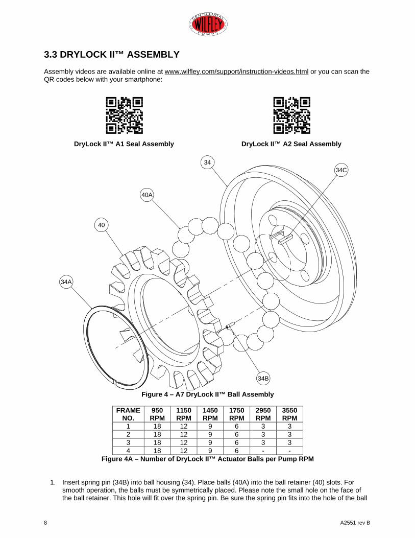
3.3 DRYLOCK II™ ASSEMBLY Assembly videos are available online at www.wilfley.com/support/instruction-videos.html or you can scan the QR codes below with your smartphone:
DryLock II™ A1 Seal Assembly
DryLock II™ A2 Seal Assembly
Figure 4 – A7 DryLock II™ Ball Assembly
FRAME
NO. 950 RPM
1150 RPM
1450 RPM
1750 RPM
2950 RPM
3550 RPM
1 18 12 9 6 3 3 2 18 12 9 6 3 3 3 18 12 9 6 3 3 4 18 12 9 6 - -
Figure 4A – Number of DryLock II™ Actuator Balls per Pump RPM
1. Insert spring pin (34B) into ball housing (34). Place balls (40A) into the ball retainer (40) slots. For
smooth operation, the balls must be symmetrically placed. Please note the small hole on the face of the ball retainer. This hole will fit over the spring pin. Be sure the spring pin fits into the hole of the ball
34A
34B
40
40A
3434C

A2551 rev B 9
CENTRIFUGAL
P U M P S
retainer. Then align ball retainer into ball housing (34). Lock into place with retaining ring (34A) to the hub of the ball housing. Lastly, insert key (34C) onto ball housing.
Figure 5 – A7 Rotating DryLock II™ Assembly Step 1
2. Slide o-ring (24H) over seal sleeve (24). Make sure it is in the groove after the threads. Slide rotary
seal ring (24G) over o-ring then tighten with lock nut (24F). Insert slide ring (24B) into seal sleeve. **NOTE: Lock nut (24F) has left hand threads**
24F
24G
24H
24B24
APPLY TEFLON®
LUBRICATIONTO THREADS

10 A2551 rev B
CENTRIFUGAL
P U M P S
Figure 6 – A7 Rotating DryLock II™ Assembly, Step 2
3. Slide wave spring (42) over shaft sleeve (39). Place o-ring (24A) into groove in the shaft sleeve. Lubricate o-ring and then carefully insert into the completed assembly from the previous step. Take care when pushing the shaft sleeve past the slide ring (24B). Try to center the keyway directly between the tapped holes in the assembly created in Step 1. Then install o-ring (20) into the groove in the shaft sleeve (39).
2042
39
24A
COMPLETEDASSEMBLY FROMPREVIOUS STEP

A2551 rev B 11
CENTRIFUGAL
P U M P S
Figure 7 – A7 Stationary DryLock II™ Assembly Step 1
4. Press disaster bushing (26H) into cartridge seal (26). Insert o-ring (30B) and lubricate prior to inserting
the stationary seal ring (23) into cartridge seal. When installing the stationary seal ring, make sure that the tabs in the part align with the slots in the seal cartridge (26). Insert o-ring (26J) into the groove in the seal cartridge. Carefully inspect the stationary seal ring (23) to insure that it has seated fully before installation. The inside surface of the seal ring is the stationary seal face and must be free of scratches or nicks.
23
30B
26H
26J
26

12 A2551 rev B
CENTRIFUGAL
P U M P S
Figure 8 – A7 Stationary DryLock II™ Assembly Step 2 – Varilip Configuration
5. VARILIP CONFIGURATION: Press the Varilip seal (31A) into the seal housing (30) with the lip facing
toward the suction of the pump.
Figure 9 – A7 Stationary DryLock II™ Assembly Step 2 – Wiper Seal Configuration
WIPER SEAL CONFIGURATION: Insert the Wiper Seal (31A) into the seal housing (30). Bend the seal into a crescent moon shape in order to fit it into the angled groove. Make sure that the seal is completely inserted in the groove before continuing.
30
31A
30
31A

A2551 rev B 13
CENTRIFUGAL
P U M P S
Figure 10 – A7 Complete DryLock II™ Assembly
6. Insert Rotating Assembly Step 2 into Stationary Assembly Step 2. Apply Teflon paste generously to threads of Stationary Assembly Step 1 and lubricate o-ring before threading into Stationary Assembly Step 2. **Do not overtighten – Leave 1 visible thread.** Tighten actuator plate (43) with flat cap screws (24C) and drive screw sleeves (24D). It is recommended that “blue Loctite” be applied to the cap screws (24C) to ensure they do not unscrew during operation. Recheck that the keyway in the shaft sleeve is directly between the flat cap screws. Insert the key (34) into the keyway in the shaft sleeve. Slide the Ball Housing Assembly over the Rotating Assembly created in Step 1 and lock it with retaining ring (39A). Adjustment may be needed to make sure that the cap screws, key and ball housing assembly fit correctly.
*Note: The complete DryLock II™ Assembly can be purchased fully assembled and ready to install.*
COMPLETED ROTATINGASSEMBLY STEP 2
34
COMPLETEDBALL HOUSINGASSEMBLY
39A
24C24D
43
COMPLETED STATIONARYASSEMBLY STEP 1
COMPLETED STATIONARYASSEMBLY STEP 2

14 A2551 rev B
CENTRIFUGAL
P U M P S
Figure 11 – A7 Complete Pump Assembly
7. Lubricate o-ring (20). Install the DryLock II™ Assembly to the power end. The seal flush should be at
the 12 o’clock position and the drain at the 6 o’clock position. A drain nipple (29) may have been supplied with the DryLock® II seal. The nipple can be screwed in to the drain port after pump assembly, use Teflon tape on the threads.
COMPLETEDRYLOCK II™SEAL ASSEMBLY
29
1
143
1A
1915
30A17
18
A2551 rev B 15
CENTRIFUGAL
P U M P S
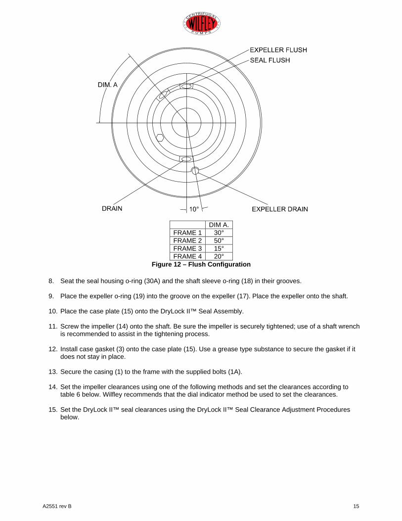
DIM A.FRAME 1 30° FRAME 2 50° FRAME 3 15° FRAME 4 20°
Figure 12 – Flush Configuration
8. Seat the seal housing o-ring (30A) and the shaft sleeve o-ring (18) in their grooves.
9. Place the expeller o-ring (19) into the groove on the expeller (17). Place the expeller onto the shaft.
10. Place the case plate (15) onto the DryLock II™ Seal Assembly.
11. Screw the impeller (14) onto the shaft. Be sure the impeller is securely tightened; use of a shaft wrench is recommended to assist in the tightening process.
12. Install case gasket (3) onto the case plate (15). Use a grease type substance to secure the gasket if it does not stay in place.
13. Secure the casing (1) to the frame with the supplied bolts (1A).
14. Set the impeller clearances using one of the following methods and set the clearances according to table 6 below. Wilfley recommends that the dial indicator method be used to set the clearances.
15. Set the DryLock II™ seal clearances using the DryLock II™ Seal Clearance Adjustment Procedures below.

16 A2551 rev B
CENTRIFUGAL
P U M P S
Impeller Clearance Cold temperature clearance (in.) for various service temperatures Standard A7 Pump See table below for clearances between casing and impeller.
Table 1 – Casing and Impeller Clearances
+/- 0.001” Tolerance Dial Indicator Procedures
Figure 13 – Dial Indicator Method (Preferred
Method)
1. Set indicator so that button contacts the end of the shaft (62).
2. Loosen jam nuts (72B) on jacking bolts (75) and back jack bolts out two turns.
3. Tighten each retaining bolt (75) evenly drawing the bearing carrier (72) towards the frame (61) until the impeller (14) contacts the casing (1). Turn the shaft to ensure contact is made.
4. Set indicator to zero and back the retaining
bolts out one turn.
5. Tighten the jacking bolts so they evenly (about one flat at a time) move the bearing carrier away from the frame until the indicator shows the clearance for your pump (see chart).
6. Evenly tighten all jack and retaining bolts so that they are equally tight. Recheck the dial indicator to ensure the proper clearance has been maintained.
7. Check shaft to be sure it turns freely.
Feeler Gauge Procedures
Figure 14 – Feeler Gauge Method
1. Loosen jam nuts (72B) on jacking bolts (75)
and back out approximately two turns.
2. Tighten each retaining bolt (75) evenly, drawing bearing carrier (72) towards the frame (61) until the impeller (14) contacts the casing (1). Turn the shaft (62) to ensure contact is made.
3. With a feeler gauge, set the gap between the three sets of bolts and bearing carrier that corresponds to the proper clearance for your pump (see Table 1).
4. Evenly back out bearing carrier using the
three jacking bolts until it contacts the retaining bolts. Evenly tighten jam nuts.
5. Check shaft to be sure it turns freely.
Max. Service Temp.
Frame 1
Frame 2
Frame 3
Frame 4
200°F (93°C) 0.010 0.011 0.013 0.017
250°F (121°C) 0.012 0.013 0.015 0.019
300°F (149°C) 0.014 0.015 0.017 0.021
400°F (204°C) 0.017 0.018 0.020 0.024
A2551 rev B 17
CENTRIFUGAL
P U M P S
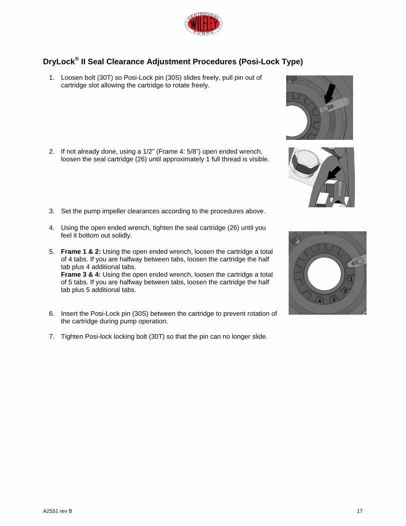
DryLock® II Seal Clearance Adjustment Procedures (Posi-Lock Type)
1. Loosen bolt (30T) so Posi-Lock pin (30S) slides freely, pull pin out of cartridge slot allowing the cartridge to rotate freely.
2. If not already done, using a 1/2” (Frame 4: 5/8”) open ended wrench,
loosen the seal cartridge (26) until approximately 1 full thread is visible.
3. Set the pump impeller clearances according to the procedures above.
4. Using the open ended wrench, tighten the seal cartridge (26) until you feel it bottom out solidly.
5. Frame 1 & 2: Using the open ended wrench, loosen the cartridge a total of 4 tabs. If you are halfway between tabs, loosen the cartridge the half tab plus 4 additional tabs. Frame 3 & 4: Using the open ended wrench, loosen the cartridge a total of 5 tabs. If you are halfway between tabs, loosen the cartridge the half tab plus 5 additional tabs.
6. Insert the Posi-Lock pin (30S) between the cartridge to prevent rotation of the cartridge during pump operation.
7. Tighten Posi-lock locking bolt (30T) so that the pin can no longer slide.
1
2 3
4
18 A2551 rev B
CENTRIFUGAL
P U M P S
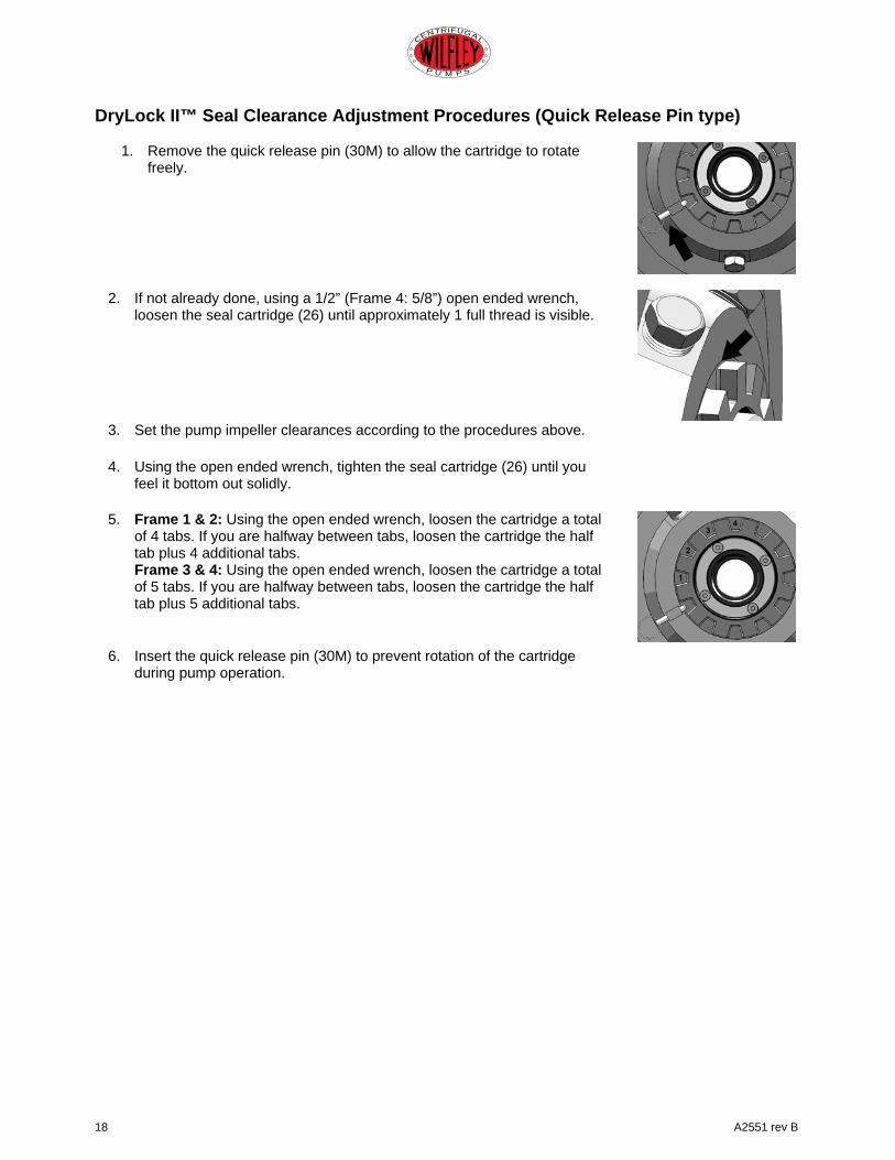
DryLock II™ Seal Clearance Adjustment Procedures (Quick Release Pin type)
1. Remove the quick release pin (30M) to allow the cartridge to rotate freely.
2. If not already done, using a 1/2” (Frame 4: 5/8”) open ended wrench, loosen the seal cartridge (26) until approximately 1 full thread is visible.
3. Set the pump impeller clearances according to the procedures above.
4. Using the open ended wrench, tighten the seal cartridge (26) until you feel it bottom out solidly.
5. Frame 1 & 2: Using the open ended wrench, loosen the cartridge a total of 4 tabs. If you are halfway between tabs, loosen the cartridge the half tab plus 4 additional tabs. Frame 3 & 4: Using the open ended wrench, loosen the cartridge a total of 5 tabs. If you are halfway between tabs, loosen the cartridge the half tab plus 5 additional tabs.
6. Insert the quick release pin (30M) to prevent rotation of the cartridge
during pump operation.
A2551 rev B 19
CENTRIFUGAL
P U M P S
4.0 ORDERING PARTS Please include the serial number of your pump when ordering spare parts. With this number we can determine and duplicate the original configuration and materials of construction. 5.0 SPECIAL SERVICE The seal assembly is extremely important to the total, efficient operation of Wilfley A7 pumps. Its parts, gaskets and seals must be in good working order. Many times parts are replaced unnecessarily due to unfamiliarity with the assembly. The reverse is also true: parts that should be replaced are, at times, left in the assembly. For these reasons, we provide the service of rebuilding this assembly in our factory.
Your Wilfley A7 pumps and seals may be returned to the factory, at any time, for complete overhaul and repair. Each pump is completely disassembled and worn or inoperable parts are replaced. All rebuilt pumps are subjected to the same testing procedures as newly constructed units. We charge the standard price for parts and a minimal reassembly fee.
The utilization of this service provides you with almost instantaneous pump repair at an economical price. The units are overhauled and returned to you quickly. Please contact A.R. Wilfley and Sons, Inc. or any of our authorized representatives at any time concerning our pumps or parts. You can be assured that we will do all within our power to ensure your complete satisfaction with Wilfley products.
A.R Wilfley and Sons, Inc. P.O. Box 2330 Denver, Colorado 80201 1-(303) 779-1777 1-(800) 525-9930 www.wilfley.com
20 A2551 rev B
CENTRIFUGAL
P U M P S
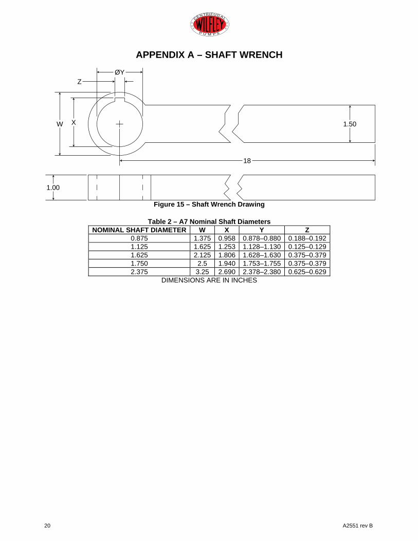
APPENDIX A – SHAFT WRENCH
Figure 15 – Shaft Wrench Drawing
Table 2 – A7 Nominal Shaft Diameters
NOMINAL SHAFT DIAMETER W X Y Z 0.875 1.375 0.958 0.878–0.880 0.188–0.192 1.125 1.625 1.253 1.128–1.130 0.125–0.129 1.625 2.125 1.806 1.628–1.630 0.375–0.379 1.750 2.5 1.940 1.753–1.755 0.375–0.379 2.375 3.25 2.690 2.378–2.380 0.625–0.629
DIMENSIONS ARE IN INCHES
Z
W X
1.00
18
1.50
ØY

A2551 rev B 21
CENTRIFUGAL
P U M P S
APPENDIX B – A7 Bolt Torque Values
Table 3 – A7 Bolt Torque Values SAE Grade 2 (ft-lbs) SAE Grade 5 (ft-lbs)
Bolt Size TPI Torque Bolt Size TPI Torque 1/4 20 4 1/4 20 7 5/16 18 8 5/16 18 13 3/8 16 14 3/8 16 23 1/2 13 34 1/2 13 55 5/8 11 70 5/8 11 110 3/4 10 110 3/4 10 200 7/8 9 150 7/8 9 320 1 8 225 1 8 480
1-1/8 7 350 1-1/8 7 580 1-1/4 7 500 1-1/4 7 600* 1-3/8 6 550* 1-3/8 6 600* 1-1/2 6 600* 1-1/2 6 600* 1-3/4 5 600* 1-3/4 5 600*
2 4.5 650* 2 4.5 650* 18-8 and 316 Stainless (ft-lbs) METRIC Class 8.8 (ft-lbs)
1/4 20 4 6mm 1.00 4 5/16 18 8 8mm 1.00 12 3/8 16 14 10mm 1.25 30 1/2 13 34 12mm 1.25 40 5/8 11 70 14mm 1.25 65 3/4 10 110 16mm 2.00 100 7/8 9 150 18mm 2.00 135 1 8 225 22mm 2.50 210
1-1/8 7 350 24mm 3.00 315 1-1/4 7 500 1-3/8 6 550* 1-1/2 6 600*
Note: Lubricate all fastener threads before tightening.