DryLin N Low Profile - igus® Inc.DryLin® N Low Profile Linear Guide Systems 46.4 The DryLin® N...
14
DryLin ® N Low Profile Linear Guide System ® ®
Transcript of DryLin N Low Profile - igus® Inc.DryLin® N Low Profile Linear Guide Systems 46.4 The DryLin® N...

• Corrosion-resistant
• Wear-resistant
• Resistant to contaminants
• Low coefficient of friction
• Extremely quiet operation
• Lightweight
DryLin® N Low ProfileLinear Guide System
®®

DryLin® N Selection Guide
Available
Carriages
DryLin® N17• Good for tight design constraints• Low cost• Excellent for low loads• Excellent corrosion resistance
DryLin® N27• Through hole for flexible mounting• Threaded boss for easy attachment• Extremely low friction/low wear• Replaceable glide pads• Low weight• Flexible size• Excellent for low to medium loads• High temperature version available
DryLin® N40• Flexible size• Replaceable glide pads• Excellent for medium to high loads• Wide base for stable design
DryLin® N80• Use one rail instead of two
narrow rails• High accelerations possible• Replaceable glide pads• Extremely low friction/low wear • Good for higher loads
Online LifetimeCalculationwww.igus.com
Standard Preload
Double Carriage
Standard/holes Standard/thread Preload
Overmolded
iglide® J carriageDouble lengthwith thread
Zinc carriageDouble lengthwith holes
Standard/holes Standard/thread Overmold/holes
Standard/thread Overmold/thread
Overmold/thread

Dimensional
Drawing
Maximum
Load
Maximum
Speed
Rail
Material
Carriage
Material
11 lbs(50 N)
49 fps(15 m/s)
AnodizedAluminum
Brass / Plastic
110 - 168 lbs(490 - 750 N)Depending onthe carriage
49 fps(15 m/s)
AnodizedAluminum
Chromated Zinc /Plastic
orBrass / Plastic
157 lbs(700 N)
49 fps(15 m/s)
AnodizedAluminum
Chromated Zinc /Plastic
220 lbs(1000 N)
49 fps(15 m/s)
AnodizedAluminum
Chromated Zinc /Plastic
Aluminumavailable
↕ 6mm
17 mm
↕ 9.5mm
27 mm
↕ 9.5mm
40 mm
↕ 12mm
80 mm
®
DryLin® N Low Profile Linear Guide Systems
46.4
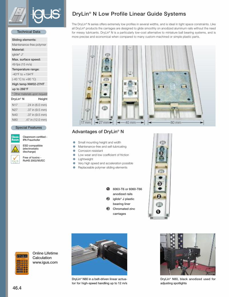
The DryLin® N series offers extremely low profiles in several widths, and is ideal in tight space constraints. Likeall DryLin® products the carriages are designed to glide smoothly on anodized aluminum rails without the needfor messy lubricants. DryLin® N is a particularly low-cost alternative to miniature ball bearing systems, and ismore precise and economical when compared to many custom-machined or simple plastic parts.
l Small mounting height and width
l Maintenance-free and self-lubricating
l Corrosion-resistant
l Low wear and low coefficient of friction
l Lightweight
l Very high speed and acceleration possible
l Replaceable polymer sliding elements
6063-T6 or 6060-T66
anodized rails
iglide® J plastic
bearing liner
Chromated zinc
carriages
Advantages of DryLin® N
DryLin® N Height
N17 .24 in (6.0 mm)
N27 .37 in (9.5 mm)
N40 .37 in (9.5 mm)
N80 .47 in (12.0 mm)
DryLin® N80, black anodized used foradjusting spot lights
DryLin® N80 in a belt- driven linear ac tua -tor for high-speed handling up to 12 m/s
Sliding elements:
Maintenance-free polymer
Material:
iglide® J*
Max. surface speed:
49 fps (15 m/s)
Temperature range:
-40°F to +194°F
(-40 °C to +90 °C)
High temp NW02-27HT
up to 266°F
* Other materials upon request
17 mm 40 mm 80 mm27 mm
Online LifetimeCalculationwww.igus.com
Technical Data
Special Features
Clean-Room
ESD compatible(electrostaticdischarge)
Cleanroom certified - IPA Fraunhofer
Free of toxins - RoHS 2002/95/EC

DryLin® N Low Profile Linear Guide Systems
46.5
PDF: www.igus.com/drylin-pdfs
CAD: www.igus.com/drylin-CAD
RoHS info: www.igus.com/RoHS
DryLin
®N
Linear Guide Systems
®
Part No. for single carriages:
Carriages Carriage/Bearing Material/Color Mounting Description Max Static
Style Load
NW-02-17 Plastic/Brass/iglide J/Yellow Threaded brass boss Standard 11 lbs (50N)
NW-02-17 P Plastic/Brass/iglide J/Yellow Threaded brass boss Preloaded 11 lbs (50N)
NW-22-17-40 Plastic/Brass/iglide J/Yellow Threaded brass boss Overmolded, double-length version 11 lbs (50N)
NW-01-27 Chromated Zinc/iglide/Yellow Through holes Standard, clip-on plastic 112 lbs (500N)
NW-01-27 P Zinc/iglide J/Yellow Through holes Preloaded .22 lbs (1N) 112 lbs (500N)
NW-01-27HT High temp 266°F
NW-11-27 Zinc/iglide J/Yellow Through holes Overmolded plastic, with through holes 112 lbs (500N)
NW-11-27-SS Stainless Steel/iglide J/Yellow Through holes Overmolded plastic, with through holes 168 lbs (750N)
NW-02-27 Zinc/iglide J/Yellow Threaded bosses Standard, clip-on plastic 112 lbs (500N)
NW-02-27 P Zinc/iglide J/Yellow Threaded bosses Preloaded .22 lbs (1N) 112 lbs (500N)
NW-02-27HT High temp 266°F
NW-12-27 Zinc/iglide J/Yellow Threaded bosses Overmolded plastic, with through holes 112 lbs (500N)
NW-11-27-80 Zinc/iglide J200/Grey Through holes Overmolded, double-length version 167 lbs (740N)
NW-21-27-60P Plastic/iglide J/Yellow Brass through holes 50% longer, preloaded 112 lbs (500N)
NW-22-27-60P Plastic/iglide J/Yellow Brass threaded boss 50% longer, preloaded 112 lbs (500N)
NW-01-40 Chromated Zinc/iglide J/Yellow Through holes Standard. clip-on plastic 157 lbs (700N)
NW-02-40 Chromated Zinc/iglide J/Yellow Threaded bosses Standard. clip-on plastic 157 lbs (700N)
NW-12-40 Chromated Zinc/iglide J/Yellow Threaded bosses Overmolded plastic 157 lbs (700N)
NW-02-80 Chromated Zinc/iglide J/Yellow Threaded, no bosses Standard. clip-on plastic 225 lbs (1000N)
NW-12-80 Chromated Zinc/iglide J/Yellow Threaded, no bosses Overmolded 225 lbs (1000N)
NW-02-80AL Aluminum/iglide J/Yellow Threaded, no bosses Standard. clip-on plastic 250 lbs (1111N)
Part No. for single rails:Rail Material Description Maximum Length
NS-01-17 6063-T6 or 6060-T66 anodized aluminum M3 Mounting holes 6.5 ft
NS-01-17S 6063-T6 or 6060-T66 anodized aluminum No holes 6.5 ft
NS-01-27 6063-T6 or 6060-T66 anodized aluminum M4 Mounting holes 12 ft (4000 mm special order)
NS-01-27S 6063-T6 or 6060-T66 anodized aluminum No holes 12 ft (4000 mm special order)
NS-01-40 6063-T6 or 6060-T66 anodized aluminum M4 Mounting holes 12 ft (4000 mm special order)
NS-01-40S 6063-T6 or 6060-T66 anodized aluminum No holes 12 ft (4000 mm special order)
NS-01-80 6063-T6 or 6060-T66 anodized aluminum M4 Mounting holes 12 ft (4000 mm special order)
NS-01-80S 6063-T6 or 6060-T66 anodized aluminum No holes 12 ft (4000 mm special order)
DryLin® N Low Profile Linear Guide Systems - NK-02-17®
46.6
DryLin
®N
Linear Guide Systems
Internet: http://www.igus.com
email: sales@
igus.com
QuickS
pec: http://www.igus.com/drylin-quickspec
Telephone1-800-521-2747
Fax
1-401-438-7270
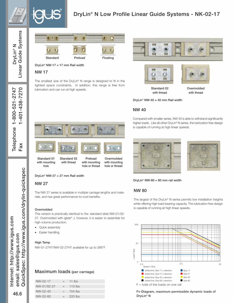
Maximum loads (per carriage)
NW-02-17 = 11 lbs
NW-01/02-27 = 110 lbs
NW-02-40 = 154 lbs
NW-02-80 = 220 lbs
0.3 332
20
200
dotted line: Size 17 z-direction
dotted line: Size 27 z-direction
dotted line: Size 40 z-direction
dotted line: Size 80 z-direction
Size 17 z-direction
Size 27 z-direction
Size 40 z-direction
Size 80 z-direction
Speed v (ft/s)
Load
F (l
bs)
3.5
F = total of the loads on one rail
Fv-Diagram, maximum permissible dynamic loads ofDryLin® N
Preloadwith mountinghole or thread
Overmoldedwith mountinghole or thread
Standard 02with thread
Standard 01with mounting
hole
DryLin® NW-17 = 17 mm Rail width
DryLin® NW-40 = 40 mm Rail width
DryLin® NW-80 = 80 mm rail widthDryLin® NW-27 = 27 mm Rail width
Standard 02 with thread
Overmoldedwith thread
Preload FloatingStandard
NW 80
The largest of the DryLin® N series permits low installation heightswhile offering high load-bearing capacity. The lubrication free designis capable of running at high linear speeds.
NW 40
Compared with smaller series, NW 40 is able to withstand significantlyhigher loads. Like all other DryLin® N series, the lubrication free designis capable of running at high linear speeds.
NW 27
The NW 27 series is available in multiple carriage lengths and mate-rials, and has great performance-to-cost benefits.
OvermoldedThis version is practically identical to the standard slide NW-01/02-27. Overmolded with iglide® J, however, it is easier to assemble forhigh volume production.
• Quick assembly
• Easier handling
High Temp
NW-01-27HT/NW-02-27HT available for up to 266°F
NW 17
The smallest size of the DryLin® N range is designed to fit in thetightest space constraints. In addition, this range is free fromlubrication and can run at high speeds.

DryLin® N Low Profile Linear Guide Systems
46.7
PDF: www.igus.com/drylin-pdfs
CAD: www.igus.com/drylin-CAD
RoHS info: www.igus.com/RoHS
DryLin
®N
Linear Guide Systems
®
When using systems with 2 parallel rails, one side must be designated as the “fixed” rail, and the opposite side the “floating” rail.
Why use floating bearings?• promotes smooth gliding performance and maximizes bearing life• prevents binding caused by parallelism and angle errors• decreases necessary drive force and wear by minimizing friction-forces• Enhances the precision of the system over the bearings’ lifetime.• Reduce assembly time and cost
Fixed BearingsThe “fixed” bearing rail should be positioned closest tothe drive force. This rail will determine the precision ofthe system; no system should contain more than two“fixed” bearings.
Floating/Self-Aligning BearingsThe “floating” rail should be the rail located furthest fromthe drive force. It acts only as a guide, and compensatesfor any misalignments or angle errors in the system,ensuring proper functionality.
Mounting SurfacesThe mounting surfaces for rails and bearings should havea very flat surface (e.g milled surface) in order to enhanceperformance. Variations in these surfaces may becompensated for by using floating bearings.
Fixed and Floating Bearing Mounting Instructions
Eccentric Forces
2:1 Rule =
permissible distances
of the applied forces
Online LifetimeCalculationwww.igus.com
The 2 :1 RuleWhen using linear plain bearings it is important to ensure that the acting forcesfollow the 2:1 Rule (see drawing). If either the load or the drive force (F) isgreater than twice the bearing length (1X), then binding or interrupted motionmay occur.If the location of the drive force or load cannot be changed, simply increasethe distance between the bearings, or create a counterbalance to move thecenter-of-gravity back within the 2 to 1 ratio.
Standard Version
Maximum float = ± .02” (.5 mm)
Horizontal Float “LLZ”
Vertical Float “LLY”
DryLin® N - Floating Systems
Part No.Fixed Bearing - CARRIAGE ONLY
NW-02-17
NW-02-27 / NW-02-27
NW-02-40
NW-02-80
Part No.Horizontal Floating - CARRIAGE ONLY
NW-02-17 LLZ
NW-01-27 LLZ
NW-02-27 LLZ
NW-02-40 LLZ
NW-02-80 LLZ
Part No.Vertical Floating - CARRIAGE ONLY
NW-02-17 LLY
NW-01-27 LLY
NW-02-27 LLY
NW-02-40 LLY
NW-02-80 LLY
Vertical Float “LLYZ”
Part No.Horizontal/Vertical Floating - CARRIAGE ONLY
NW-02-17 LLYZ
NW-01-27 LLYZ
NW-02-27 LLYZ
NW-02-40 LLYZ
NW-02-80 LLYZ
Automatic compensation ofparallelism errors
Floating Fixed

DryLin® N Low Profile Linear Guide Systems - NK-02-17®
46.8
DryLin
®N
Linear Guide Systems
Internet: http://www.igus.com
email: sales@
igus.com
QuickS
pec: http://www.igus.com/drylin-quickspec
Telephone1-800-521-2747
Fax
1-401-438-7270
Structure of the Part No.
Complete system
Thread
Size
“P” for preloaded
Number of carriages
Length of rail (mm)
S =
min
. 2
1
6 ±0
,3
Dep
th fo
r sc
r ew
tigh
teni
ng
max
. s +
2. 5
m
in.
s +
0. 5
for Machine Scr ews M3 DIN 7984/DIN 6912/DIN 84 EN ISO 1707
9. 6
Hole min. ø 5
M3
17 -0.2mm0
Max. torque .59 lbf • ft (0.8 Nm)
C5 = 20 - 49 ± 1mm
mm 14
20
60 C6 = 20 - 49 ± 1mm
mm
max. 2000 ± 2mm
1
11 lb s
l y = 1700 mm 4
W b = 200 mm 3
M x = .44 lbf · ft (0.31 Nm)
11 lb s l z = 120 mm 4
W b = 33 mm 3
M y = .13 lbf · ft (0.18 Nm)
M z = .13 lbf · ft (0.18 Nm)
y
x
z
Static load-bearing capacity andgeometric moment of inertia
NW-22-17-40
NW-02-17(P)
CAD files online:www.igus.com
NW-02-17Standard
NW-22-17-40Double Length
NW-02-17PPreloaded
NK -02 -17 -2P -500
Carriages Carriage/Bearing Material/Color Mounting Description Weight Max Static
Style Load
NW-02-17 Plastic/Brass/iglide J/Yellow Threaded brass boss Standard .06 oz (1.7g) 11 lbs (50N)
NW-02-17P Plastic/Brass/iglide J/Yellow Threaded brass boss Preloaded .23 lbs (1N) .06 oz (1.7g) 11 lbs (50N)
NW-22-17-40 Plastic/Brass/iglide J/Yellow Threaded brass boss Overmolded, double-length version .09 oz (2.6g) 11 lbs (50N)
-LLZ for floating in Z-direction, best for horizontal applications for rail alignment
-LLY for floating in Y-direction, best for vertical applications or when flatness of the mounting surface is of concern
-LLYZ for floating in both directions
Floating carriages (see page 21.6 about fixed and floating
Rail Material Description Weight Hole Pattern Max Length
NS-01-17 Anodized AL M3 Mounting holes 0.1 lbs/ft (150 g/m) Bore pattern symmetrical C%=C6 6.5 ft
NS-01-17S Anodized AL No holes 0.1 lbs/ft (150 g/m) NA 12 ft
No cut charges for standard C5/C6, overall length tolerances, minimum of 100 mm.

Carriages Carriage/Bearing Material/Color Mounting Description Weight Max Static
Style Load
Standard
NW-01-27 Chromated Zinc/iglide J/Yellow Through holes Standard, clip-on plastic .38 oz (10.8g) 112 lbs (500N)
NW-02-27 Chromated Zinc/iglide J/Yellow Threaded bosses Standard, clip-on plastic .44 oz (12.5g) 112 lbs (500N)
Overmolded
NW-11-27 Chromated Zinc/iglide J/Yellow Through holes Overmolded plastic .38 oz (10.8g) 112 lbs (500N)
NW-12-27 Chromated Zinc/iglide J/Yellow Threaded bosses Overmolded plastic .44 oz (12.5g) 112 lbs (500N)
Preloaded
NW-01-27P Chromated Zinc/iglide J/Yellow Through holes Preloaded .22 lbs (1N), clip-on .38 oz (10.8g) 112 lbs (500N)
NW-02-27P Chromated Zinc/iglide J/Yellow Threaded bosses Preloaded .22 lbs (1N), clip-on .44 oz (12.5g) 112 lbs (500N)
High Temp
NW-01-27HT Chromated Zinc/high temp Through holes High temp up to 266°F .38 oz (10.8g) 112 lbs (500N
NW-02-27HT Chromated Zinc/high temp Threaded bosses High temp up to 266°F .44 oz (12.5g) 112 lbs (500N)
-LLZ for floating in Z-direction, best for horizontal applications for rail alignment
-LLY for floating in Y-direction, best for vertical applications or when flatness of the mounting surface is of concern
-LLYZ for floating in both directions
Floating carriages (see page 21.6 about fixed and floating
Rail Material Description Weight Hole Pattern Max Length
NS-01-27 Anodized AL M4 Mounting holes 0.2 lbs/ft (290 g/m) Bore pattern symmetrical C5=C6 3658 mm
NS-01-27S Anodized AL No holes 0.2 lbs/ft (290 g/m) NA 3658 mm
No cut charges for standard C5/C6, overall length tolerances, and minimum 100 mm
DryLin® N Low Profile Linear Guide SystemsNK-01-27 / NK-02-27
46.9
PDF: www.igus.com/drylin-pdfs
CAD: www.igus.com/drylin-CAD
RoHS info: www.igus.com/RoHS
DryLin
®N
Linear Guide Systems
®
CAD files online: www.igus.com
NW-01-27(P)/NW-11-01Carriages with through hole
Standard cut length tolerance is ± 2 mm Standard cut length tolerance is ± 2 mm
NW-02-27(P)/NW-12-01Carriages with threaded boss
C5 =
mm 20
30
*40
60
20- 49 ± 1 mm
C5 = 20- 49 ± 1 mm
mm 20
30
*40
60
Static load-bearing capacity and geometric moment of inertia
* Length of overmolded carriages version NW-11-27 and NW-12-27: 34 ± 0.7 mm
NK-02-27(P)
22 0 -0.4
9. 5
0.4
-0.4
3
1. 5
14
27
0. 8
1. 5
1. 5
for Machine “Low Head” Screws M4DIN 7984 / DIN 6912 DIN 84 / EN ISO 1707
Hole min. Ø 6.5
s =
min
. 5
M4 max. torque .88 lbf · ft (1.2 Nm)
min
. s
- 1
max
. s +
4.5
Scr
ew le
ngth
112 lb s
l y = 6524 mm 4
M x = 3.7 lbf · ft (5 Nm)
112 lb s l z = 588 mm 4
M y = 1.84 lbf · ft (2
M z = 1.84 lbf · ft (2
112 lb s
l y = 6524 mm 4
112 lb s l z = 588 mm 4
M x = 3.7 lbf · ft (5 Nm)
M y = 1.84 lbf · ft (2.5 Nm)
M z = 1.84 lbf · ft (2.5 Nm)
NK-01-27(P)
DryLin® N Low Profile Linear Guide SystemsNW-11-27-80 Double Length Version
®
46.10
DryLin
®N
Linear Guide Systems
Internet: http://www.igus.com
email: sales@
igus.com
QuickS
pec: http://www.igus.com/drylin-quickspec
Telephone1-800-521-2747
Fax
1-401-438-7270
Carriages Carriage/Bearing Material/Color Mounting Description Weight Max Static
Style Load
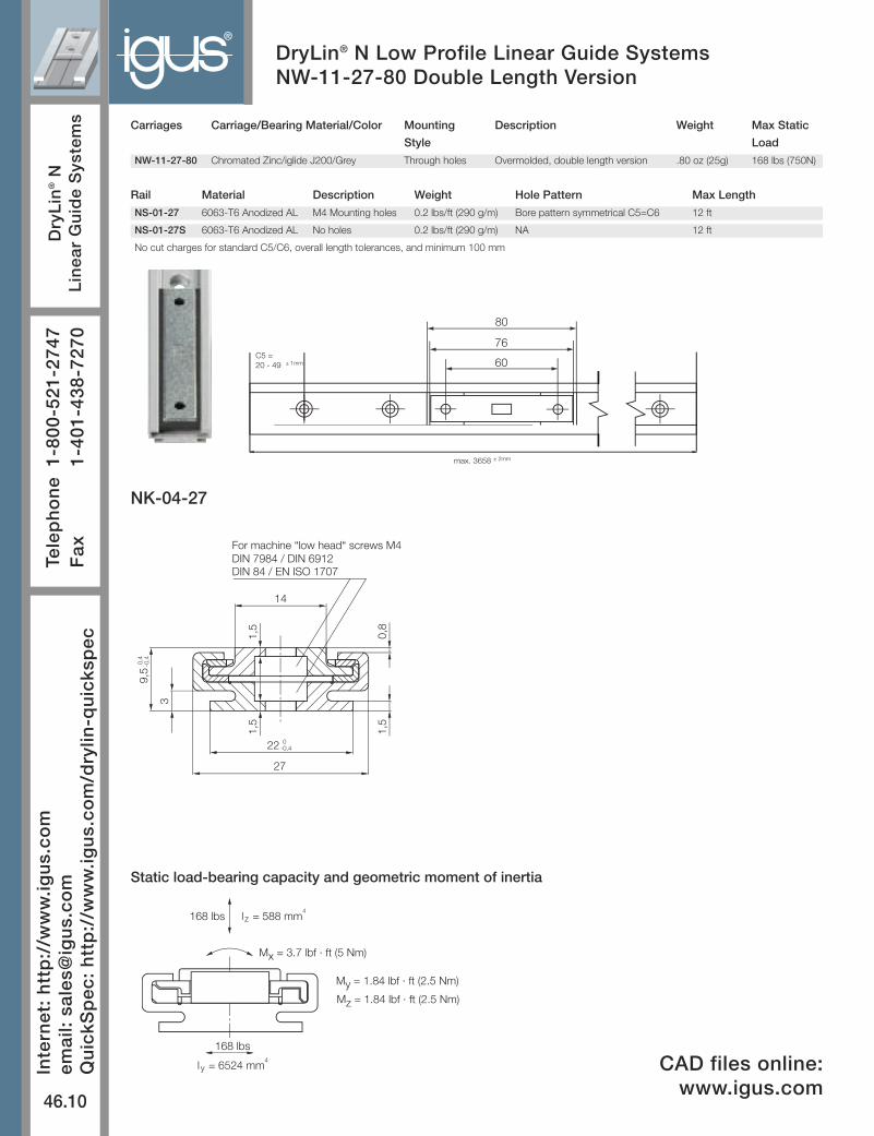
NW-11-27-80 Chromated Zinc/iglide J200/Grey Through holes Overmolded, double length version .80 oz (25g) 168 lbs (750N)
Rail Material Description Weight Hole Pattern Max Length
NS-01-27 6063-T6 Anodized AL M4 Mounting holes 0.2 lbs/ft (290 g/m) Bore pattern symmetrical C5=C6 12 ft
NS-01-27S 6063-T6 Anodized AL No holes 0.2 lbs/ft (290 g/m) NA 12 ft
No cut charges for standard C5/C6, overall length tolerances, and minimum 100 mm
Static load-bearing capacity and geometric moment of inertia
NK-04-27
22 0 -0,4
9, 5
0,4
-0,4
3
1, 5
14
27
0, 8
1, 5
1, 5
For machine “low head“ screws M4DIN 7984 / DIN 6912DIN 84 / EN ISO 1707
168 lb s
l y = 6524 mm 4
M x = 3.7 lbf · ft (5 Nm)
168 lb s l z = 588 mm 4
M y = 1.84 lbf · ft (2.5 Nm)
M z = 1.84 lbf · ft (2.5 Nm)
76
60
80
C5 = 20 - 49 ± 1mm
max. 3658 ± 2mm
CAD files online:www.igus.com
DryLin® N Low Profile Linear Guide Systems,Preloaded 50% longer than standard
46.11
PDF: www.igus.com/drylin-pdfs
CAD: www.igus.com/drylin-CAD
RoHS info: www.igus.com/RoHS
DryLin
®N
Linear Guide Systems
®
Carriages Carriage/Bearing Material/Color Mounting Description Weight Max Static
Style Load
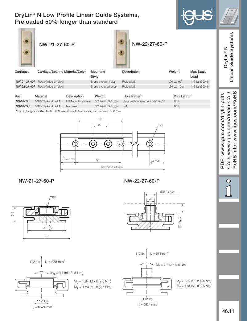
NW-21-27-60P Plastic/iglide J/Yellow Brass through holes Preloaded .29 oz (9g) 112 lbs (500N)
NW-22-27-60P Plastic/iglide J/Yellow Brass threaded boss Preloaded .39 oz (12g) 112 lbs (500N)
Rail Material Description Weight Hole Pattern Max Length
NS-01-27 6063-T6 Anodized AL M4 Mounting holes 0.2 lbs/ft (290 g/m) Bore pattern symmetrical C%=C6 12 ft
NS-01-27S 6063-T6 Anodized AL No holes 0.2 lbs/ft (290 g/m) NA 12 ft
No cut charges for standard C5/C6, overall length tolerances, and minimum 100 mm
C520-49± 1 mm 60 C6=C5
20
60
K1
max. 3658 ± 2 mm
112 lb s
l y = 6524 mm 4
M x = 3.7 lbf · ft (5 Nm)
112 lb s l z = 588 mm 4
M y = 1.84 lbf · ft (2.5 Nm)
M z = 1.84 lbf · ft (2.5 Nm)
112 lb s
l y = 6524 mm 4
112 lb s l z = 588 mm 4
M x = 3.7 lbf · ft (5 Nm)
M y = 1.84 lbf · ft (2.5 Nm)
M z = 1.84 lbf · ft (2.5 Nm)
K3
22
9.5
0–0.4
27
K2
min. Ø 6.5
min
.5
NW-21-27-60-P NW-22-27-60-P
NW-21-27-60-P NW-22-27-60-P

Structure of the Part No. – Standard version
Length of rail (mm)
Number of carriagesSizeThreadComplete system
DryLin® N Low Profile Linear Guide SystemsNW-01/02-40
®
46.12
DryLin
®N
Linear Guide Systems
Internet: http://www.igus.com
email: sales@
igus.com
QuickS
pec: http://www.igus.com/drylin-quickspec
Telephone1-800-521-2747
Fax
1-401-438-7270
157 lbs
157 lbs
I = 970 mm4
Wb = 170 mm3
Mx = 12 lbf · ft (10 Nm)
My = 4.4 lbf · ft (6 Nm)Mz = 4.4 lbf · ft (6 Nm)
I = 26400 mm4
Wb = 660 mm3
Hole Min. Ø 6.5
40
1.4
9.5
0.8
s=m
in.5
23
For machine screws M4DIN 7984/DIN 6912/DIN 84EN ISO 1707 / EN ISO 7045
M4 - max. torque 11 lbf - in (1.2 Nm)
C5 = 20-49.5 mm ±1 mm
(C5 = C6)
50
40
20
60
max. 3560 ± 2mm
C5 = 20-49.5 mm ±1 mm
(C5 = C6)
NK -02 -40 -2 -500
DryLin® NK – Complete system
* Length of carriages overmoldedversion NW-12-40: 52 mm
*
** For NW-02-40 only
Static load-bearing capacity and geometricmoment of inertia
CAD files online: www.igus.com
Carriages Carriage/Bearing Material/Color Mounting Description Weight Max Static
Style Load
NW-01-40 Chromated Zinc/iglide J/Yellow Through holes Standard, clip-on plastic 1.06 oz (30g) 157 lbs (700N)
NW-02-40 Chromated Zinc/iglide J/Yellow Threaded bosses Standard, clip-on plastic 1.06 oz (30g) 157 lbs (700N)
NW-12-40 Chromated Zinc/iglide J/Yellow Threaded bosses Overmolded plastic 1.06 oz (30g) 157 lbs (700N)
-LLZ for floating in Z-direction, best for horizontal applications for rail alignment
-LLY for floating in Y-direction, best for vertical applications or when flatness of the mounting surface is of concern
-LLYZ for floating in both directions
Rail Material Description Weight Hole Pattern Max Length
NS-01-40 6063-T6 Anodized AL M4 Mounting holes 0.3 lbs/ft (450 g/m) Bore pattern symmetrical C%=C6 12 ft
NS-01-40S 6063-T6 Anodized AL No holes 0.3 lbs/ft (450 g/m) NA 12 ft
No cut charges for standard C5/C6, overall length tolerances, and minimum 100 mm
NW-02-40 NW-01-40
**
**

DryLin® N Low Profile Linear Guide Systems - NK-02-80
46.13
PDF: www.igus.com/drylin-pdfs
CAD: www.igus.com/drylin-CAD
RoHS info: www.igus.com/RoHS
DryLin
®N
Linear Guide Systems
®
igus
56
68
80*
150
40**
M4
max. 3560 ± 2mm
C 5 = 25-99.5 mm ± 1mm C 6 = 25-99.5 mm ± 1mm
DIN 7984/DIN 6912/DIN 8440**
1.6
80
12+
0.3
–0.
3
45
57Tightening depth max. 6.5
For mounting screwsM4 - max. torque 18 lbf · in.
EN ISO 1707
± 1mm
225 lb s
I=2900 mm W b =380 mm
225 lb s 4
3
M x = 23.9 lbf · ft (32.4 Nm)
M y = 11 lbf · ft (15 Nm)
M z = 11 lbf · ft (15 Nm)
y
x
z
* carriage length for overmolded NW-12-80 = 83 mm
** size 45 on request
-02 -40 -2 -500
Structure of the Part No. – Standard version
Carriage option Standard - Leave blankFloating z-direction - LLZFloating y-direction - LLYFloating y- and z-direction - LLYZ
Length of rail (mm)Number of carriagesSizeThreadComplete system
Static load-bearing capacity and geometricmoment of inertia
CAD files online: www.igus.com
Online LifetimeCalculationwww.igus.com
-LLZNK
Carriages Carriage/Bearing Material/Color Mounting Description Weight Max Static
Style Load
NW-02-80 Chromated Zinc/iglide J/Yellow Threaded no bosses Standard, clip-on plastic 3.53 oz (100g) 225 lbs (1000N)
NW-12-80 Chromated Zinc/iglide J200/Grey Threaded no bosses Overmolded 3.53 oz (100g) 225 lbs (1000N)
NW-02-80AL Aluminum/iglide J/Yellow Threaded no bosses Aluminum, clip-on plastic 2.56 oz (72g) 250 lbs (1111N)
Rail Material Description Weight Hole Pattern Max Length
NS-01-80 6063-T6 Anodized AL M4 Mounting holes 0.3 lbs/ft (450 g/m) Bore pattern symmetrical C5=C6 12 ft
NS-01-80S 6063-T6 Anodized AL No holes 0.3 lbs/ft (450 g/m) NA 12 ft
No cut charges for standard C5/C6, overall length tolerances, and minimum 100 mm

DryLin® N Low Profile Linear Guide Systems - End Caps
®
46.14
DryLin
®N
Linear Guide Systems
Internet: http://www.igus.com
email: sales@
igus.com
QuickS
pec: http://www.igus.com/drylin-quickspec
Telephone1-800-521-2747
Fax
1-401-438-7270
S
T
Easy assembly by hand. Disassemble by
using a screwdriver
End caps for rail size 40, bolted
DryLin® N end caps
DryLin® N end caps are available forevery size rail
• Easy assembly• Cost-effective• Dismantling possible• High retention force
Dimensions (mm)Part number S T For rail
NSKB-17 1.5 7 NS-01-17
NSKB-27 2 8 NS-01-27
NSKB-80 2 17 NS-01-80
NSK-40 1.5 8 NS-01-40