Further development of the poroelastic road surface within ...

Drying-induced stresses in poroelastic drops on rigid substrates
Matthew G. Hennessy,1, ∗ Richard V. Craster,2 and Omar K. Matar3
1Department of Engineering Mathematics, University of Bristol,Ada Lovelace Building, Bristol, BS8 1TW, United Kingdom
2Department of Mathematics, Imperial College London,South Kensington Campus, London, SW7 2AZ, United Kingdom3Department of Chemical Engineering, Imperial College London,South Kensington Campus, London, SW7 2AZ, United Kingdom
We develop a theory for drying-induced stresses in sessile, poroelastic drops undergoing evapo-ration on rigid surfaces. Using a lubrication-like approximation, the governing equations of three-dimensional nonlinear poroelasticity are reduced to a single thin-film equation for the drop thickness.We find that thin drops experience compressive elastic stresses but the total in-plane stresses aretensile. The mechanical response of the drop is dictated by the initial profile of the solid skeleton,which controls the in-plane deformation, the dominant components of elastic stress, and sets a limiton the depth of delamination that can potentially occur. Our theory suggests that the alignmentof desiccation fractures in colloidal drops is selected by the shape of the drop at the point of gela-tion. We propose that the emergence of three distinct fracture patterns in dried blood drops is aconsequence of a non-monotonic drop profile at gelation. We also show that depletion fronts, whichseparate wet and dry solid, can invade the drop from the contact line and localise the generationof mechanical stress during drying. Finally, the finite element method is used to explore the stressprofiles in drops with large contact angles.
I. INTRODUCTION
The drying behaviour of thin films and drops is impor-tant to a multitude of industries and applications. Thepresence of a particulate phase introduces appreciablechanges to the evaporative process and leads to hydrody-namic and mechanical instabilities, sometimes resultingin cracking. While traditionally viewed as detrimental,the onset of cracking can play an advantageous role ina number of modern applications, from affordable med-ical diagnostics [1] to high-resolution, high-throughputnano-patterning [2]. With such a broad range of appli-cations, there is a growing need for efficient and accuratemodelling capabilities of the stresses accompanying theevaporation of particle-laden films and drops. Yet con-siderable complexity arises in these drying systems fromthe delicate interplay between capillarity, thermocapil-larity, heat and mass transfer, contact lines (undergoingpinning and de-pinning), and, crucially, the formation ofa poroelastic network, which controls the formation ofcracks and their morphology. In this paper, we focus onthe development of a theory for drying-induced stressesin sessile, poroelastic drops undergoing evaporation onrigid surfaces.
Many important patterning behaviours manifest dur-ing the evaporation of droplets [3] due to the interac-tion between evaporation-driven flows and the contactline [4]. The commonly encountered ‘coffee-ring’ stain isone such example, where evaporation in the presence ofa non-volatile solute promotes the appearance of a dis-tinctly inhomogeneous deposit. Deegan et al. [5–7] first
explained the origin of this effect by the presence of anincreased evaporative flux at the contact line, coupledwith a resultant capillary-induced restoration flow.
Crack formation in drying colloidal drops is thought tobe a multi-step process originating from the coffee-ringeffect [8, 9]. The radially outwards capillary flow trans-ports colloids to the pinned contact line where they accu-mulate due to weak, counteracting diffusive effects [10].Gelation occurs once the particle concentration exceedsa critical value, resulting in the local transformation ofthe liquid drop into a poroelastic solid; the porous elas-tic material then has an elastic skeleton with intercon-nected pores containing fluid. A gelation front conse-quently emerges from the contact line and propagatestowards the drop centre [11]. Mechanical stresses developin the gelled region because of the competing effects ofevaporation-driven contraction of the solid skeleton andits adhesion to the substrate. Cracks therefore emerge asa mechanism to relieve mechanical stress.
Experiments have shown that a myriad of fracture pat-terns can occur during droplet evaporation [12]. Whenan aqueous drop with silica nanoparticles dries, fracturestypically nucleate at the contact line and travel radiallyinwards, following the gelation front. These fractures di-vide the deposit into an array of ‘petals’ that simulta-neously delaminate from the substrate, resulting in theentire solid ‘blooming’ into a structure that resembles alotus flower [13, 14]. In the case of dried blood drops,the solid deposit often has an orthoradial fracture at thecontact line, an annular region with several radial frac-tures, and a central zone with smaller-scale fractures withno preferred orientation [15]. Extensive experimental re-search has been carried out to elucidate the dependenceof the fracture pattern on the contact angle [16, 17], dry-ing rate [18–20], substrate deformability [21], and particle
arX
iv:2
111.
0699
2v2
[co
nd-m
at.s
oft]
13
Mar
202
2

2
hydrophobicity [22] and concentration [23, 24]. However,a detailed theoretical description of stress generation indrying colloidal drops is lacking, with treatments relyingon scaling analyses [25] or one-dimensional models thatdo not capture the evolving and non-uniform thicknessof the drop [20, 26].
Our work will deploy three-dimensional nonlinearporoelasticity to build a comprehensive model of drying-induced mechanical stresses in drops with a pre-existingsolid structure. Moreover, a lubrication-like approxima-tion will be invoked to systematically reduce the gov-erning equations. Poroelasticity theory is based on thepremise that the solid phase is arranged into a porousand deformation structure referred to as the ‘solid skele-ton’. Biot developed the theory of poroelasticity [27–29]to account for the two-way coupling between the defor-mation of the solid skeleton and fluid flow within thepore space. The theory formalised by Biot assumes thedeformation of the solid skeleton is infinitesimal and thusdescribes the solid skeleton as a linearly elastic material.When the solid deformation is no longer infinitesimal, onemust derive poroelastic models in the framework of non-linear elasticity [30, 31]. The lubrication approximationhas been used in tandem with the theory of poroelastic-ity [32, 33] to study thin films for various applicationssuch as CO2 sequestration [34], imbibition [35], soft con-tact [36, 37], and biomechanics [38, 39].
By combining poroelasticity with the lubrication ap-proximation, we are able to provide novel physical in-sights into the internal droplet dynamics. In the caseof axisymmetric drops with circular contact lines, wefind that the initial profile of the poroelastic drop playsa critical role in selecting the modes of in-plane defor-mation, thereby determining whether the radial or hoopstresses dominate. Our work suggests that the fracturepatterns appearing in drying colloidal drops are dictatedby the shape of the drop at the point of gelation, in agree-ment with the experimental observations of Bourrianneet al. [24]. By comparing the magnitude of the radial andhoop stresses, we correctly predict the emergence of threedistinct fracture patterns in dried drops of blood [11].We also find that the drop profile affects the depth ofdelamination, which may not reach the drop centre, inline with the experiments of Osman et al. [26]. We showthat a sharp decrease in the permeability during dry-ing can result in the formation of depletion fronts thatinvade the bulk of the drop from the contact line andlocalise the accumulation of stresses. Finally, finite ele-ment simulations are used to calculate the stress profilesin poroelastic drops with large contact angles. We findthat many of the conclusions obtained from the reducedmodel still apply.
The rest of this paper is organised as follows. InSection II, details of the problem formulation and non-dimensionalisation are provided. The governing equa-tions are asymptotically reduced in Section III. The re-sults are discussed in Section IV, while Section V is de-voted to the concluding remarks.
II. PROBLEM FORMULATION
We consider a drop of fluid consisting of a volatilesolvent (e.g. water) and a non-volatile colloidal compo-nent (e.g. nanoparticles) that dries on a horizontal non-deformable solid substrate. We envision the colloids ashaving formed a poroelastic solid from which evaporationoccurs. The contact line is assumed to remain pinned,which is in agreement with experiments, and the time-dependent contact angle ϕ(t) is assumed to be small. Thecharacteristic height and lateral extent (e.g. the radius)of the drop are denoted by H and R, respectively, whereH/R � 1. We work within the framework of nonlin-ear poroelasticity [31] to account for large deformationsduring drying. We also assume that the drop remainsbonded to the underlying substrate and thus neglect de-lamination processes that can potentially occur.
A. Kinematics
The governing equations are formulated in terms of Eu-lerian coordinates x = xiei associated with the current(deformed) configuration, where ei are Cartesian basisvectors and summation over repeated indices is implied.We let X = Xiei denote Lagrangian coordinates asso-ciated with the initial (undeformed) configuration of thedrop. During drying, the solid element originally locatedatX is displaced to x, thereby generating a displacementus = x−X(x, t). The deformation gradient tensor F andits determinant J = detF describe the distortion andvolumetric changes of material elements, respectively. InEulerian coordinates, the deformation gradient tensor ismost readily expressed in terms of its inverse as
F−1 = ∇X = I−∇us, (1)
where ∇ is the spatial gradient taken with respect to theEulerian coordinates x. We adopt the convention that∇us = (∂usi/∂xj) ei ⊗ ej . The velocity of the fluid andsolid are written as vf and vs, respectively. In Eulerianformulations of nonlinear elasticity, the rate of change ofdisplacement is linked to the velocity by the relationship
∂us
∂t+ (vs · ∇)us = vs, (2)
where us = 0 when t = 0.
B. Balance laws
The composition of the mixture is described by the vol-ume fractions of fluid and solid, φf and φs, respectively.Conservation of liquid and solid yield
∂φf
∂t+∇ · (φfvf ) = 0, (3a)
∂φs
∂t+∇ · (φsvs) = 0. (3b)

3
In deriving (3), it has been assumed that the densitiesof the solid skeleton and the fluid are constant, that is,both phases are incompressible. Furthermore, it is as-sumed that no volume change occurs upon mixing andthat material elements only consist of solid and fluid, thelatter of which leads to the condition
φf + φs = 1. (4)
Since the pore space is only occupied by fluid, the volumefraction of fluid φf also represents the porosity of thesolid. Due to the incompressibility of the fluid and solid,volumetric changes in material elements can only be dueto imbibition or depletion of fluid within the pore space,leading to the relationship
J = detF =1− φf01− φf
, (5)
where φf0 represents the fluid fraction in the initial un-deformed configuration. For simplicity, we assume that
φf0 is spatially uniform. The Jacobian determinant J de-scribes the local contraction of the solid skeleton (J < 1)that occurs due to the loss of fluid from the pore space
(φf < φf0 ). If the porosity φf remains spatially uni-form during drying, then the Jacobian determinant canbe written in terms of the total drop volume V asJ(t) = V (t)/V (0).
The fluid within the pore space is assumed to be trans-ported by pressure gradients. Hence, we impose Darcy’slaw,
φf (vf − vs) = −k(φf )
µf∇p, (6)
where k is the permeability of the solid skeleton, µf isthe fluid viscosity, and p is the pressure. The contractionof the solid matrix during drying will reduce the poresize and hence decrease the permeability. Deformation-driven changes in the permeability are captured throughits dependence on the porosity. In particular, we adopta normalised Kozeny–Carmen law [40, 41] for the perme-ability given by
k(φf )
k0=
(1− φf0 )2
(φf0 )3(φf )3
(1− φf )2, (7)
where k0 is the permeability of the initial configuration.Conservation of momentum for the two-phase mixture
yields
∇ · σ = ∇p, (8)
where σ is the effective (Terzaghi) elastic stress tensor ofthe solid [30], which commonly appears in soil mechan-ics [27, 42]. The solid skeleton is assumed to be isotropicand obey a neo-Hookean equation of state. The elasticcomponent of the stress tensor can be written as
σ =νE
(1 + ν)(1− 2ν)(J − 1)I +
E
2(1 + ν)J(B− I), (9)
where E is the Young’s modulus, ν is Poisson’s ratio(both assumed constant), I is the identity tensor, and
B = FFT is the left Cauchy–Green tensor. In the limit ofsmall deformations, ∇us � 1, we find that F ∼ I+∇us,which implies that B ∼ I + ∇us + (∇us)T and J =detF ∼ 1 +∇ · us. Hence, the stress-strain relation (9)reduces to
σ ∼ νE
(1 + ν)(1− 2ν)(∇ · us)I
+E
2(1 + ν)
(∇us + (∇us)T
), (10)
thus recovering linear elasticity.It is convenient to decompose vector and tensor quan-
tities into in-plane and transverse components that areparallel and perpendicular to the substrate, respectively.We let x3 = z and X3 = Z denote the transverse Eu-lerian and Lagrangian coordinates, respectively, and lete3 = ez be the corresponding basis vector. If a = aieidenotes an arbitrary vector, then we write a = a‖+azez,where a‖ = aαeα is a vector of the in-plane compo-nents and az = a3 is the transverse component; herewe adopt the convention that Greek indices are equalto 1 or 2. Similarly, we introduce the in-plane gradi-ent operator ∇‖ = ∇ − ez ∂/∂z. The symmetric elas-tic stress tensor σ is written in terms of its in-planecomponents σ‖ = σαβeα ⊗ eβ , transverse shear com-ponents σ⊥ = σα3eα, and vertical component σzz asσ = σ‖ + σ⊥ ⊗ ez + ez ⊗ σ⊥ + σzzez ⊗ ez. Similar de-compositions will be used for other tensorial quantitiesas well.
C. Boundary and initial conditions
We assume that the solid skeleton perfectly adheres tothe rigid substrate, resulting in a no-displacement condi-tion
us = 0, z = 0. (11)
In addition, the substrate is taken to be impermeable;therefore,
vf · ez = 0, z = 0. (12)
The static contact line of the drop is denoted by the curverc‖ and defined by the equation
h = 0, x‖ = rc‖. (13)
The kinematic boundary conditions for the fluid and solidphase at the free surface are given by
ρfφf (vf · n− vn) = φfqe, z = h(x‖, t), (14a)
ρsφs(vs · n− vn) = 0, z = h(x‖, t), (14b)
where ρf and ρs are the densities of the fluid and solid,respectively; qe = qe(φ
f ) is the evaporative mass flux
4
which depends on the surface composition; and vn is thenormal velocity of the free surface, defined as
vn =1
(1 + |∇‖h|2)1/2∂h
∂t. (15)
Continuity of stress at the drop surface is given by
σ · n− pn = 0, z = h(x‖, t), (16)
where the atmospheric pressure has been set to zero.Similar boundary conditions on the stress have beenused by other researchers when modelling drying-inducedstresses in colloidal suspensions [43, 44]. The initial con-ditions for the fluid fraction, displacement, and dropthickness are given by
φf (x, 0) = φf0 , (17a)
us(x, 0) = 0, (17b)
h(x‖, 0) = h0(x‖). (17c)
The initial conditions can be placed in the contextof drying colloidal dispersions by connecting the quan-
tities h0 and φf0 to the profile of the drop and the vol-ume fraction of liquid at the point of gelation. The gelpoint depends on the nature of the colloids as well as theevaporation conditions, as these control the possible ar-rangements of particles (e.g. random close packing, face-centred cubic). The experimental observation of gelationfronts implies that different regions of the drop undergothe sol-gel transition at different times, making it difficultto define a profile for h0. However, some insights can beobtained from the shape of the solid deposit that remainson the substrate when drying is complete. Anyfantakiset al. [22] examined the drying of aqueous drops contain-ing silica nanoparticles; by increasing the hydrophobic-ity of the nanoparticles, they observed that the final de-posit takes on a parabolic profile. Therefore, the colloidslikely remained uniformly dispersed during drying, whichwould have resulted in a homogeneous gelation when thedrop had a parabolic profile. However, by decreasing thehydrophobicity of the particles, the deposit had a non-monotonic profile. Given the different profiles that mightarise during drying, we will treat h0 as a parameter withthe aim of elucidating the role it plays in determining theporomechanical response of the drop.
D. Scaling and non-dimensionalisation
We scale spatial quantities according to x‖ ∼ R, z ∼H, h ∼ H, and define ε = H/R � 1. For the liquid,we choose the usual lubrication scales for the velocity,
vf‖ ∼ V and vfz ∼ εV , where the velocity scale V will be
defined below. We use an advective time scale given byt ∼ R/V .
To facilitate identifying appropriate scales for the solid,we assume that the linear stress-strain relation given by
(10) applies. Balancing vsz with ∂h/∂t in the kinematicboundary condition (14b) implies that vsz ∼ εV . More-over, balancing ∂usz/∂t with vsz in the vertical compo-nent of (2) gives a scale for the vertical displacement:usz ∼ H. A scale for the vertical normal stress can thenbe obtained as σzz ∼ E ∂usz/∂z ∼ E. We postulatethat large horizontal contractions of the solid skeleton areprohibited by its adhesion to the substrate. Therefore,the removal of solvent will drive a predominantly verti-cal contraction of the solid skeleton. The elastic stressthat is generated by this vertical contraction, σzz, mustbe balanced by the pressure, p, resulting in p ∼ σzz ∼ E.A scale for the horizontal displacements can be obtainedthrough a consideration of the horizontal momentum bal-ance for the mixture. As in lubrication theory, we ex-pect the horizontal pressure gradient to generate a shearstress. Therefore, we balance ∂σ⊥/∂z with ∇‖p whichimplies that σ⊥ ∼ εE. The shear stress also scales likeσ⊥ ∼ E ∂us‖/∂z; thus, we find that ∂us‖/∂z ∼ ε. In
light of the no-slip condition for the solid, this balanceimplies that us‖ ∼ εH and hence vs‖ ∼ ε2V . The in-
plane components of the stress tensor can be scaled asσ‖ ∼ E. Finally, the velocity scale is determined fromthe horizontal component of Darcy’s law, which givesV = (k0/µf )(E/R).
Under this scaling, the non-dimensional displacementgradient is
∇us = ε2∇‖us‖ + ε
(∂us‖
∂z⊗ ez + ez ⊗∇‖usz
)+∂usz∂zez ⊗ ez, (18)
which shows that in-plane and shear strains will be small.The non-dimensional form of the elastic stress tensor isσ = σ‖ + σzzez ⊗ ez + ε(σ⊥ ⊗ ez + ez ⊗ σ⊥).
1. Non-dimensional bulk equations
The rescaled conservation equations for the volumefractions are given by
∂φf
∂t+∇‖ ·
(φfvf‖
)+
∂
∂z
(φfvfz
)= 0, (19a)
∂φs
∂t+ ε2∇‖ ·
(φsvs‖
)+
∂
∂z(φsvsz) = 0. (19b)
Thus, fluid is transported in both the horizontal and ver-tical directions. The solid, however, is predominantlytransported in the vertical direction, suggesting that auniaxial mode of deformation occurs. The componentsof the solid velocity can be obtained from
∂us‖
∂t+ ε2vs‖ · ∇‖u
s‖ + vsz
∂us‖
∂z= vs‖, (20a)
∂usz∂t
+ ε2vs‖ · ∇‖usz + vsz
∂usz∂z
= vsz. (20b)
5
Darcy’s law (6) can be written in component form as
φf (vf‖ − ε2vs‖) = −k(φf )∇‖p, (21a)
ε2φf (vfz − vsz) = −k(φf )∂p
∂z, (21b)
which shows that vertical gradients in the pressure willbe weak. The in-plane motion of the solid skeleton playsa sub-dominant role in (21a) and can be neglected. Con-sequently, the problems describing the in-plane transportof solid and fluid decouple. The momentum balance forthe mixture (8) is
∇‖ · σ‖ +∂σ⊥∂z
= ∇‖p, (22a)
ε2∇‖ · σ⊥ +∂σzz∂z
=∂p
∂z. (22b)
The lubrication approximation for poroelastic solidstherefore leads to a different stress balance than for vis-cous fluids by bringing the in-plane stresses σ‖ and thevertical normal stress σzz into the leading-order problem.
2. Non-dimensional boundary and initial conditions
The non-dimensional adhesion and no-flux conditionsare the same as in (11) and (12). The kinematic bound-ary conditions become
∂h
∂t+ vf‖ · ∇‖h− v
fz = −Qq(φf )A, z = h(x‖, t), (23a)
∂h
∂t+ ε2vs‖ · ∇‖h− v
sz = 0, z = h(x‖, t), (23b)
where Q = q0/(ρfV ε), q0 = qe(φf0 ) is the initial evapo-
rative mass flux, and A =(1 + ε2|∇‖h|2
)1/2. The non-
dimensional parameter Q plays the role of a Peclet num-ber by characterising the relative rate of evaporation tobulk fluid transport. The stress balances at the free sur-face are given by
−σ‖ · ∇‖h+ σ⊥ + p∇‖h = 0, z = h(x‖, t), (24a)
−ε2σ⊥ · ∇‖h+ σzz − p = 0, z = h(x‖, t). (24b)
The initial conditions for the drop profile, porosity, and
displacements are h = h0(x‖), φf = φf0 , us‖ = 0, and
usz = 0 when t = 0.
E. Parameter estimation
Giorgiutti–Dauphine and Pauchard [20] conducted ex-periments on colloidal drops consisting of silica nanopar-ticles in water. They reported values of k0 ∼ 10−19 m2,E ∼ 1 GPa, µf ∼ 10−3 Pa s, and R ∼ 1 mm. The initialcontact angle ϕ0 ranged from 30◦ to 40◦, leading to val-ues of ε ∼ ϕ0 in the range of 0.5 to 0.7. The evaporation
velocity, Ve ∼ q0/ρf , can be inferred from their measure-ments of the cracking time and is found to be roughly10−9 m s−1. A conservative estimate of the Peclet num-ber based on a value of ε = 0.1 is then Q ∼ 10−3.Osman et al. [26] reported similar parameter values fortheir experiments: k0 ∼ 10−20 m2, Ve ∼ 10−8 m s−1,µf ∼ 10−3 Pa s, and R ∼ 1 mm. The Young’s mod-ulus and contact angles were not measured. However,since their colloidal dispersions were also based on silicananoparticles, we estimate that E ∼ 1 GPa. The Pecletnumber can be parameterised in terms of the initial con-tact angle as Q ∼ 10−3 ϕ−10 and is expected to be small.Finally, in the case of drying blood drops, Sobac andBrutin [9] reported that R = 4.3 mm, Ve ' 9·10−8 m s−1,and ϕ0 = 15◦. Moreover, they estimated that the diffu-sivity of fluid through the poroelastic solid was roughlyDw ' 3 · 10−8 m2 s−1, which leads to a velocity scale ofV ∼ Dw/R ' 7 · 10−6 m s−1. The corresponding Pecletnumber is Q ∼ 0.05.
III. ASYMPTOTIC REDUCTION
The dimensionless model is asymptotically reduced bytaking the limit as ε→ 0. The reduction can be decom-posed into two main steps. First, the mechanical problemis solved in terms of the fluid fraction. Second, the trans-port problems for the fluid and solid are simplified andthen combined into a thin-film-like equation for the dropthickness.
The reduction of the mechanical problem begins with aconsideration of the rescaled displacement gradient (18)and the deformation gradient tensor (1). By taking ε→ 0in (18) and substituting the result in (1), the leading-order contribution to the deformation gradient tensor canbe written as F = I‖ + Jez ⊗ ez, where I‖ = eα ⊗ eα isthe in-plane identity tensor and
J = detF =
(1− ∂usz
∂z
)−1. (25)
The Jacobian determinant J in (25) must also satisfy (5).The asymptotic reduction of the deformation gradienttensor F shows that, to leading order, the drop undergoesuniaxial deformation along the vertical direction. Theleading-order components of the elastic stress tensor are
σ‖ =ν
(1 + ν)(1− 2ν)(J − 1)I‖, (26a)
σ⊥ =1
2(1 + ν)
(J∂us‖
∂z+∇‖usz
), (26b)
σzz =1
1 + ν
[1
2(J − J−1) +
ν
1− 2ν(J − 1)
]. (26c)
By integrating the O(1) contributions to the verticalstress balance (22b), we observe that the pressure is equal

6
to the vertical normal stress,
p = σzz =1
1 + ν
[1
2(J − J−1) +
ν
1− 2ν(J − 1)
]. (27)
Taking ε→ 0 in (21b) shows that the pressure p is inde-pendent of z to leading order. Consequently, we deducethat σzz, J , and hence φf are also independent of z. Thehorizontal stress balance (22a) can now be integrated andthe stress-free condition (24a) imposed to find
σ⊥ =1
2(1 + ν)∇‖((h− z)(J−1 − J)
). (28)
Equating (26b) and (28) leads to a differential equationfor the in-plane components of the solid displacement us‖.
Furthermore, (25) provides an equation for the verticaldisplacement usz. Upon solving these equations and im-posing us = 0 at z = 0, we find that the displacementsare given by
us‖ =1
2z2∇‖(log J) + zJ−1∇‖
(h(J−1 − J)
), (29a)
usz = (1− J−1)z. (29b)
At this point, the mechanical problem has been com-pletely solved in terms of the Jacobian determinant J ,which is linked to the fluid fraction via (5).
At leading order, the conservation law for the fluid(19a) becomes
∂φf
∂t+∇‖ · (φfvf‖) + φf
∂vfz∂z
= 0. (30)
Integrating (30) across the thickness of the drop and us-ing the impermeability condition (12) and the kinematicboundary condition (23a) leads to
∂
∂t(hφf ) +∇‖ · (hφfvf‖) = −Qφfq(φf ). (31)
Similarly, from the conservation of solid (19b), we findthat
∂
∂t(hφs) = 0 (32)
to leading order. By integrating (32) and using the defi-nition of J from (5), we obtain
h = Jh0. (33)
Equation (33) reflects the uniaxial mode of deformationthat the drop experiences and states that volumetricchanges in material elements can only be accommodatedthrough variations in the film thickness h. Adding (31)and (32) and using Darcy’s law (21a) gives
∂h
∂t= ∇‖ ·
[k(φf )h∇‖p
]−Qφfq(φf ). (34)
By using (27) and (33) to write p = σzz(J) and J = h/h0,respectively, (34) can be formulated as a thin-film-likeequation
∂h
∂t= ∇‖ ·
[k(φf )hσ′zz
(h
h0
)∇‖(h
h0
)]−Qφfq(φf ),
(35a)
where σ′zz(J) = dσzz(J)/dJ and the solvent fraction isgiven by φf = 1− (1− φf,0)(h0/h). The thin-film equa-tion (35a) can be solved using the boundary and initialconditions
h = 0, x‖ = rc‖; (35b)
h = h0(x‖), t = 0. (35c)
Once the drop thickness h is calculated, the Jacobiandeterminant J can be computed from (33) and used toevaluate the elastic stresses and displacements given by(26)–(29).
A. The slow-evaporation limit
The parameter estimates from Sec. II E indicate thatthe Peclet number Q is typically small, implying thatfluid loss due to evaporation is slow relative to the rateat which fluid is replenished by bulk transport. Thisseparation of time scales can be used to further reducethe model. By rescaling time as t = Q−1τ and takingQ → 0, we can deduce from (35a) and (33) that h/h0and hence J must be spatially uniform. This permits thefilm thickness to be written as h(x‖, τ) = J(τ)h0(x‖).
Consequently, the fluid fraction φf must also be inde-pendent of space in order to satisfy the incompressibilitycondition (5). To determine the time dependence of J ,we integrate (35a) over the contact surface to obtain
dJ
dτ= −A0φ
fq(φf )
V0, (36)
where A0 and V0 are the (non-dimensional) area of thecontact surface and the initial volume of the drop, re-spectively, and φf = 1− (1−φf,0)/J . Equation (36) canbe recast into a differential equation for the volume ofthe drop V (τ) using the relation J(τ) = V (τ)/V0.
IV. THE POROMECHANICS OF DRYING
The solutions of the asymptotically reduced model pro-vide new insights into the poromechanics of drying drops.We first analyse and interpret the solutions for the stress.We then explore the mechanics of drying in the limitof slow evaporation, corresponding to vanishingly smallPeclet numbers Q. Numerical simulations are used tostudy the dynamics for moderate evaporation rates char-acterised by Peclet numbers that are O(1) in size. Fi-nally, we use finite element simulations to examine thestresses that arise when the contact angle is not small.

7
A. Analysis of drying-induced stresses
A key feature of the asymptotic reduction is that itallows for a straightforward determination and interpre-tation of the stresses that are generated during drying.The total stress within the poroelastic drop is charac-terised by the Cauchy stress tensor T = σ − pI and cantherefore be decomposed into an elastic stress associatedwith deformations of the solid skeleton and an isotropiccontribution arising from the fluid. Since drying leads toa loss of volume (J < 1), we see from (26a) that in-planeelastic stresses σ‖ are compressive. The origin of thesecompressive stresses can be understood by drawing onthe analogy between the drying-induced contraction ofthe solid skeleton and the vertical compression of a slabof elastic material. Due to the Poisson effect, verticalcompression of a slab will drive a lateral (or in-plane)expansion. However, if the slab is bonded to a substrate,then lateral expansion is constrained and a compressivestress is generated to resist lateral deformation. An ex-amination of the total in-plane stresses, defined by
T‖ = σ‖ − pI‖ =1
2(1 + ν)(J−1 − J)I‖, (37)
reveals they are tensile due to the negative pressure coun-teracting the elastic stresses. The combination of a ten-sile total stress and a compressive elastic stress is con-sistent with the findings of Bouchaudy and Salmon [43],who report similar mechanics in a one-dimensional set-ting.
The generation of tensile in-plane stresses leads to amechanism for fracture, which is commonly observed dur-ing the drying of complex colloidal suspensions. How-ever, the isotropic form of the in-plane stress tensor (37)prohibits the leading-order problem from providing anyinformation about the orientation of nucleated fractures,which we expect to be perpendicular to the directions ofmaximal stress. Any mechanism that could select a pref-erential direction for fracture must therefore manifest inhigher-order contributions to the stress tensor and, as aresult, be relatively weak.
Drying-induced stresses can trigger the delaminationof the drop from rigid substrates, in which case knowl-edge of the traction exerted by the drop on the substrateis crucial. The non-dimensional traction is defined asT = T|z=0 · ez. The in-plane components of the trac-tion, which are generated from elastic shear stresses, arereadily computed from (28) and found to be
T ‖ =1
2(1 + ν)∇‖(h(J−1 − J)
). (38a)
To determine the leading-order component of the verticaltraction Tz, we integrate (22b) across the thickness of thedrop and impose the stress-free condition (24b) to obtain
Tz =ε2
4(1 + ν)∇2‖(h2(J−1 − J)
). (38b)
The vertical traction (38b) can be interpreted as the ad-hesive stress required for the drop to remain bonded tothe substrate during drying. Positive and negative val-ues of Tz imply that the drop is pulling upwards andpushing downwards on the substrate, respectively. Dueto the prefactor of ε2 ∼ ϕ2
0 appearing in (38b), thin-ner drops with smaller contact angles will be less proneto delamination, provided this occurs once Tz exceedsa critical threshold. To the best of our knowledge, thecontact-angle dependence of delamination has not beeninvestigated experimentally.
B. Mechanics in the slow-evaporation limit
Significant insight into the mechanics of drying canbe obtained by considering the slow-evaporation limit,as the spatial uniformity of the Jacobian determinant Jenables the asymptotic solutions to be greatly simplified.Due to the monotonic decrease in the drop volume V intime, we can use J(t) = V (t)/V0 as a proxy for time,where J decreases from J = 1 when t = 0 to a steady-state value of J = J∞ < 1 as t → ∞. For simplicity,we focus on the case of axisymmetric drops with circularcontact lines.
The radial displacement can be computed from (29a)and is found to be
usr = z(J−1 − J)dh0dr
. (39)
Consequently, the radial and orthoradial motion of thesolid skeleton is controlled by the initial geometry of thedrop, which is encoded in the functional form of h0. Inlocations where the initial profile has a negative slope,dh0/dr < 0, solid elements are displaced towards thedrop centre (usr < 0) and undergo orthoradial compres-sion (usr/r < 0). However, if the initial profile has apositive slope, dh0/dr > 0, then solid elements are dis-placed towards the contact line (usr > 0) and undergoorthoradial expansion (usr/r > 0). Similarly, the initialcurvature of the solid skeleton, d2h0/dr
2, controls themode of radial deformation. Solid elements experience aradial compression (∂usr/∂r < 0) if the curvature is nega-tive and a radial expansion (∂usr/∂r > 0) if the curvatureis positive.
The compressive and extensional modes of radial andorthoradial deformation lead to small differences in theradial and hoop stresses. Although small, these dif-ferences can establish a preferential direction for nucle-ated fractures. By calculating the higher-order terms inthe elastic stress tensor, we find that the difference be-tween the radial and hoop stress can be expressed asTrr − Tθθ = σrr − σθθ = ε2(1 + ν)−1S(r, z), where
S =∂usr∂r− usr
r+ J
∂usr∂z
∂usz∂r
+J2
2
(∂usr∂z
)2
. (40)
The first two terms on the right-hand side of (40) cap-ture the competition between linear radial and orthora-
8
dial strains, and they would be present if the model hadbeen formulated in terms of linear elasticity. The finaltwo terms on the right-hand side of (40) arise from geo-metric nonlinearities associated with finite strains. Sub-stituting the expression for the radial displacement (39)and the vertical displacement (29b) into (40) leads to
S = (J−1 − J)z
(d2h0dr2
− 1
r
dh0dr
)+
(J2 − 1)2
2
(dh0dr
)2
.
(41)
Using (41), it is straightforward to explore how differentdrop profiles h0 affect the competition between radial andorthoradial stress generation.
Near the contact line, the initial profile of the drop canbe locally represented as a linear function with negativegradient. The resulting value of S will be positive, indi-cating that the radial stress dominates the hoop stress.Consequently, fractures will have a slight preference toalign with (be parallel to) the orthoradial direction. Dueto Trr −Tθθ being proportional to ε2 ∼ ϕ2
0, the strengthof the orthoradial alignment should increase with the ini-tial contact angle. Observations of similar qualitativetrends were made in the experimental work of Carle andBrutin [16, Fig. 4] where increases in the initial contactangle led to increasingly prominent orthoradial fracturesat the contact line.
Understanding the competition between the radial andhoop stresses away from the contact line requires specificknowledge of the initial profile of the poroelastic drop.Parabolic profiles for h0 represent a special case and leadto the first bracketed term in (41) vanishing, implyingthat the radial and orthoradial strains are identical in thelimit of linear elasticity and can only be distinguished byconsidering a nonlinear theory. Although the value of Sis always positive for parabolic drops, the prefactor of thefinal term will be small and thus any preferential orien-tation of fractures will be very weak. The drying experi-ments by Anyfantakis et al. [22] support this prediction:the solid deposits that were parabolic in shape were pat-terned by disordered fractures with no clear orientation.In this case, the parabolic profile is likely a result of thedrops remaining homogeneous during drying.
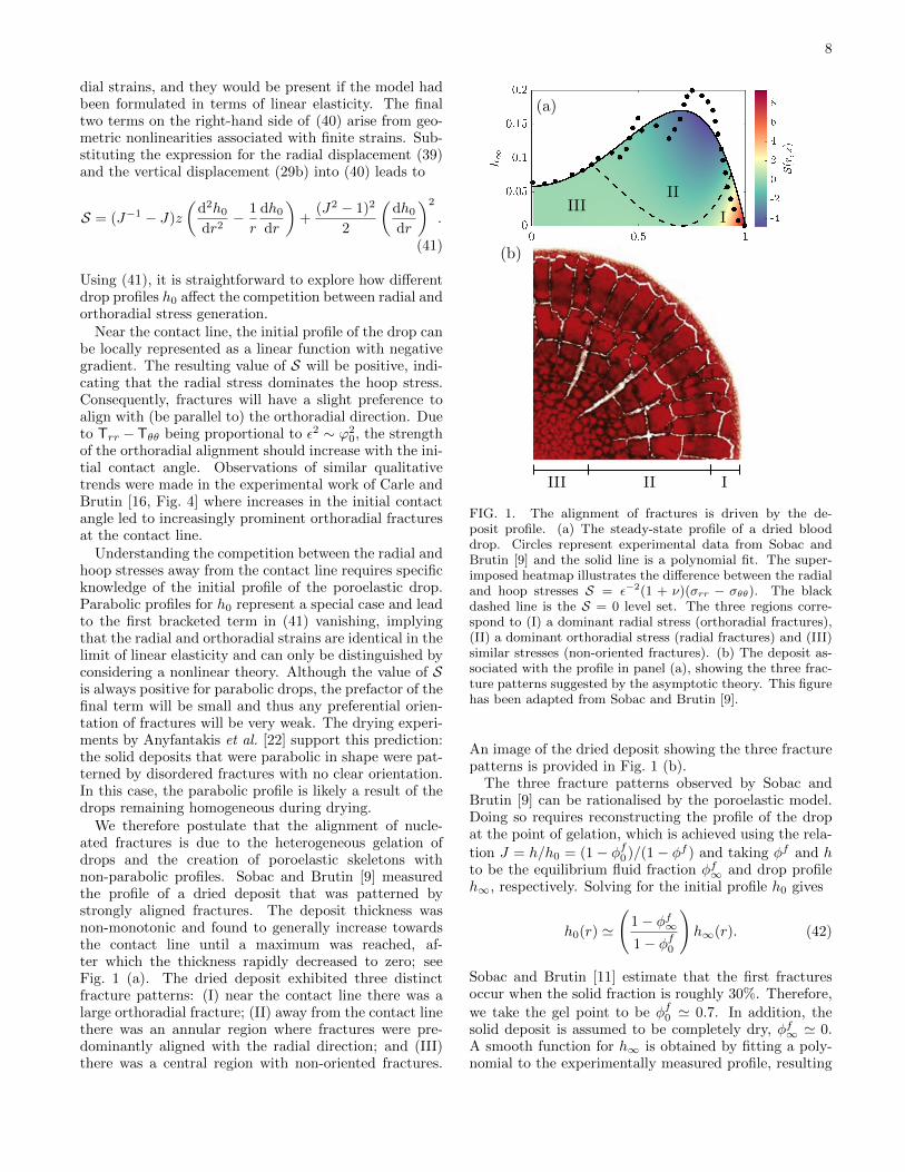
We therefore postulate that the alignment of nucle-ated fractures is due to the heterogeneous gelation ofdrops and the creation of poroelastic skeletons withnon-parabolic profiles. Sobac and Brutin [9] measuredthe profile of a dried deposit that was patterned bystrongly aligned fractures. The deposit thickness wasnon-monotonic and found to generally increase towardsthe contact line until a maximum was reached, af-ter which the thickness rapidly decreased to zero; seeFig. 1 (a). The dried deposit exhibited three distinctfracture patterns: (I) near the contact line there was alarge orthoradial fracture; (II) away from the contact linethere was an annular region where fractures were pre-dominantly aligned with the radial direction; and (III)there was a central region with non-oriented fractures.
FIG. 1. The alignment of fractures is driven by the de-posit profile. (a) The steady-state profile of a dried blooddrop. Circles represent experimental data from Sobac andBrutin [9] and the solid line is a polynomial fit. The super-imposed heatmap illustrates the difference between the radialand hoop stresses S = ε−2(1 + ν)(σrr − σθθ). The blackdashed line is the S = 0 level set. The three regions corre-spond to (I) a dominant radial stress (orthoradial fractures),(II) a dominant orthoradial stress (radial fractures) and (III)similar stresses (non-oriented fractures). (b) The deposit as-sociated with the profile in panel (a), showing the three frac-ture patterns suggested by the asymptotic theory. This figurehas been adapted from Sobac and Brutin [9].
An image of the dried deposit showing the three fracturepatterns is provided in Fig. 1 (b).
The three fracture patterns observed by Sobac andBrutin [9] can be rationalised by the poroelastic model.Doing so requires reconstructing the profile of the dropat the point of gelation, which is achieved using the rela-
tion J = h/h0 = (1− φf0 )/(1− φf ) and taking φf and hto be the equilibrium fluid fraction φf∞ and drop profileh∞, respectively. Solving for the initial profile h0 gives
h0(r) '
(1− φf∞1− φf0
)h∞(r). (42)
Sobac and Brutin [11] estimate that the first fracturesoccur when the solid fraction is roughly 30%. Therefore,
we take the gel point to be φf0 ' 0.7. In addition, thesolid deposit is assumed to be completely dry, φf∞ ' 0.A smooth function for h∞ is obtained by fitting a poly-nomial to the experimentally measured profile, resulting

9
in the solid black curve shown in Fig. 1 (a). Using thereconstruction of h0 provided by (42), we calculate thedifference between the radial and hoop stress via (41)and plot the values of S as a heatmap in Fig. 1 (a). Aspredicted, there is a region near the contact line wherethe radial stress dominates (S > 0), resulting in the or-thoradial fracture associated with pattern (I). However,there is also an intermediate region centred about themaximum of the deposit thickness where the hoop stressdominates (S < 0) and the onset of the radially alignedfractures associated with pattern (II) is expected. Fi-nally, near the drop centre, the value of S is very close tozero, suggesting the emergence of non-oriented fracturesobserved in pattern (III).
The model predicts that the appearance of multiplefracture patterns will be a generic feature of poroelas-tic skeletons that have a non-monotonic initial profile.Near a maximum in the profile, where dh0/dr ' 0 andd2h0/dr
2 < 0, the hoop stress will dominate the ra-dial stress (S < 0), suggesting the emergence of radiallyaligned fractures. Conversely, local minima in the pro-file would lead to orthoradially aligned fractures. Thepresence of multiple maxima and minima in the depositprofile shown in Fig. 1 (a) could explain the sequentialrealignment of fractures that is seen in Fig. 1 (b).
For slowly evaporating drops, the normal componentof the traction reduces to
Tz =ε2
4(1 + ν)
J2(J−1 − J)
r
d
dr
[r
d
dr
(h20)]. (43)
The competition between the decrease in the drop height,captured through J2, and the increase in elastic stress,captured through J−1 − J , results in a non-monotonicevolution of the traction that reaches a maximum valuewhen J = 2−1/2 ' 0.71. There are two ramifications ofthis finite maximum. Firstly, it implies that delamina-tion is not guaranteed to occur. Secondly, if delamina-tion does occur, then the propagating delamination frontmay not reach the drop centre by the end of the dryingprocess. In fact, the drop only pulls upwards on the sub-strate in locations where the curvature of h20 is positive.For drops with initially parabolic profiles, h0 = 1−r2, thetraction is positive for r > 2−1/2, which sets a theoreticalmaximum on the depth of delamination.
Osman et al. [26] experimentally observed a limiteddepth of delamination in drying colloidal drops. Usinga simple model, they argued that heterogeneous gelationleads to a poroelastic ‘foot’ developing at the contact line,the length of which controls the depth of delamination.Our complementary theory predicts that even a fullygelled drop could only undergo a partial degree of de-lamination. When combined, these two theories suggestthat the extent of delamination ultimately arises from anintricate interplay between the horizontal growth of theporoelastic solid as well as its shape.
C. Numerical simulations
The poromechanics that occur for larger Peclet num-bers are explored via numerical simulations of the thin-film equation (35) in an axisymmetric geometry. Theinitial profile of the drop is assumed to be parabolic;thus, we take h0(r) = 1 − r2. For simplicity, the non-dimensional evaporative mass flux is taken to be a con-stant, q(φf ) ≡ 1. As a result, all of the fluid will evapo-rate from the pores of the solid. The consequences of thissimplifying assumption on the dynamics will be discussedbelow.
The first case we consider corresponds to a moderaterate of evaporation with Q = 1. For Peclet numbers Qthat are O(1) in size, the time scale of fluid depletiondue to evaporation is commensurate with the time scaleof fluid replenishment due to bulk transport. Thus, thegeneration of composition gradients within the materialis to be expected. The initial fluid fraction, or porosity,
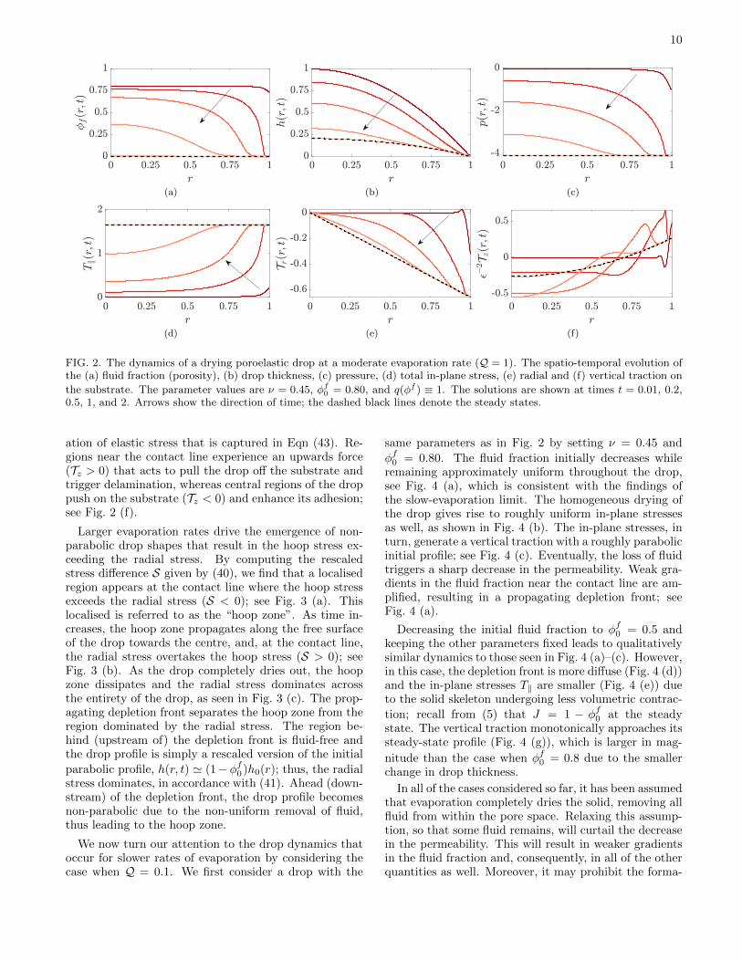
is set to φf0 = 0.80 and the Poisson’s ratio is taken to beν = 0.45. The evolution of the fluid fraction indicatesthere is a rapid loss of fluid near the contact line, whichresults in a completely collapsed (fluid-free) solid; seeFig. 2 (a). Due to the sharp decrease in the permeabilitywith the porosity, fluid from the bulk is prohibited fromreplenishing that which is lost due to evaporation. Asthe drying process continues, a depletion front invadesthe drop from the contact line while the fluid contentin the bulk decreases with a weak composition gradient.The motion of the depletion front can be detected in theevolution of the drop thickness. Upstream of the front,the drop thickness remains stationary because it has con-verged to its steady-state profile, while downstream of thefront, the drop thickness continues to decrease as fluid isremoved from the pore space; see Fig. 2 (b).
The formation of a depletion front plays a significantrole in the mechanical response of the drop. The lo-calised removal of fluid from regions near the contactline triggers a vertical compression of the solid skeletonand leads to a large decrease in the pressure, as seen inFig. 2 (c). This zone of negative pressure propagatesinto the bulk following the depletion front. In turn, thenegative pressure generates tensile stresses T‖ = T‖I‖ inboth the radial and orthoradial directions that increas-ingly penetrate into the bulk with time; see Fig. 2 (d).
The radial traction can be expressed as Tr =∂(hT‖)/∂r, which is simply the gradient of the verticallyintegrated, total radial stress. Thus, the behaviour of theradial traction largely mirrors that of the radial stress: asharp gradient develops near the contact line and prop-agates inwards, as shown in Fig. 2 (e). However, unlikethe radial stress, the radial traction settles into a non-uniform steady state due to the gradients in the dropthickness. The negative values of the radial traction im-ply that the substrate is being pulled towards the dropcentre. The vertical traction Tz exhibits non-monotonicbehaviour in time, which is likely due to the same com-petition between the decrease in drop height and gener-
10
(a) (b) (c)
(d) (e) (f)
FIG. 2. The dynamics of a drying poroelastic drop at a moderate evaporation rate (Q = 1). The spatio-temporal evolution ofthe (a) fluid fraction (porosity), (b) drop thickness, (c) pressure, (d) total in-plane stress, (e) radial and (f) vertical traction on
the substrate. The parameter values are ν = 0.45, φf0 = 0.80, and q(φf ) ≡ 1. The solutions are shown at times t = 0.01, 0.2,0.5, 1, and 2. Arrows show the direction of time; the dashed black lines denote the steady states.
ation of elastic stress that is captured in Eqn (43). Re-gions near the contact line experience an upwards force(Tz > 0) that acts to pull the drop off the substrate andtrigger delamination, whereas central regions of the droppush on the substrate (Tz < 0) and enhance its adhesion;see Fig. 2 (f).
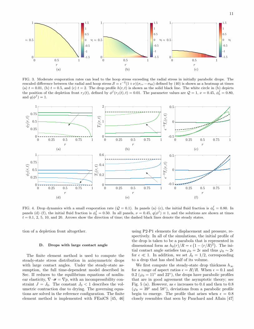
Larger evaporation rates drive the emergence of non-parabolic drop shapes that result in the hoop stress ex-ceeding the radial stress. By computing the rescaledstress difference S given by (40), we find that a localisedregion appears at the contact line where the hoop stressexceeds the radial stress (S < 0); see Fig. 3 (a). Thislocalised is referred to as the “hoop zone”. As time in-creases, the hoop zone propagates along the free surfaceof the drop towards the centre, and, at the contact line,the radial stress overtakes the hoop stress (S > 0); seeFig. 3 (b). As the drop completely dries out, the hoopzone dissipates and the radial stress dominates acrossthe entirety of the drop, as seen in Fig. 3 (c). The prop-agating depletion front separates the hoop zone from theregion dominated by the radial stress. The region be-hind (upstream of) the depletion front is fluid-free andthe drop profile is simply a rescaled version of the initial
parabolic profile, h(r, t) ' (1−φf0 )h0(r); thus, the radialstress dominates, in accordance with (41). Ahead (down-stream) of the depletion front, the drop profile becomesnon-parabolic due to the non-uniform removal of fluid,thus leading to the hoop zone.
We now turn our attention to the drop dynamics thatoccur for slower rates of evaporation by considering thecase when Q = 0.1. We first consider a drop with the
same parameters as in Fig. 2 by setting ν = 0.45 and
φf0 = 0.80. The fluid fraction initially decreases whileremaining approximately uniform throughout the drop,see Fig. 4 (a), which is consistent with the findings ofthe slow-evaporation limit. The homogeneous drying ofthe drop gives rise to roughly uniform in-plane stressesas well, as shown in Fig. 4 (b). The in-plane stresses, inturn, generate a vertical traction with a roughly parabolicinitial profile; see Fig. 4 (c). Eventually, the loss of fluidtriggers a sharp decrease in the permeability. Weak gra-dients in the fluid fraction near the contact line are am-plified, resulting in a propagating depletion front; seeFig. 4 (a).
Decreasing the initial fluid fraction to φf0 = 0.5 andkeeping the other parameters fixed leads to qualitativelysimilar dynamics to those seen in Fig. 4 (a)–(c). However,in this case, the depletion front is more diffuse (Fig. 4 (d))and the in-plane stresses T‖ are smaller (Fig. 4 (e)) dueto the solid skeleton undergoing less volumetric contrac-
tion; recall from (5) that J = 1 − φf0 at the steadystate. The vertical traction monotonically approaches itssteady-state profile (Fig. 4 (g)), which is larger in mag-
nitude than the case when φf0 = 0.8 due to the smallerchange in drop thickness.
In all of the cases considered so far, it has been assumedthat evaporation completely dries the solid, removing allfluid from within the pore space. Relaxing this assump-tion, so that some fluid remains, will curtail the decreasein the permeability. This will result in weaker gradientsin the fluid fraction and, consequently, in all of the otherquantities as well. Moreover, it may prohibit the forma-
11
(a) (b) (c)
FIG. 3. Moderate evaporation rates can lead to the hoop stress exceeding the radial stress in initially parabolic drops. Therescaled difference between the radial and hoop stress S = ε−2(1+ν)(σrr−σθθ) defined by (40) is shown as a heatmap at times(a) t = 0.01, (b) t = 0.5, and (c) t = 2. The drop profile h(r, t) is shown as the solid black line. The white circle in (b) depicts
the position of the depletion front rf (t), defined by φf (rf (t), t) = 0.01. The parameter values are Q = 1, ν = 0.45, φf0 = 0.80,and q(φf ) = 1.
(a) (b) (c)
(d) (e) (f)
FIG. 4. Drop dynamics with a small evaporation rate (Q = 0.1). In panels (a)–(c), the initial fluid fraction is φf0 = 0.80. In
panels (d)–(f), the initial fluid fraction is φf0 = 0.50. In all panels, ν = 0.45, q(φf ) ≡ 1, and the solutions are shown at timest = 0.1, 2, 5, 10, and 20. Arrows show the direction of time; the dashed black lines denote the steady states.
tion of a depletion front altogether.
D. Drops with large contact angle
The finite element method is used to compute thesteady-state stress distribution in axisymmetric dropswith large contact angles. Under the steady-state as-sumption, the full time-dependent model described inSec. II reduces to the equilibrium equations of nonlin-ear elasticity, ∇ ·σ = ∇p, with an incompressibility con-straint J = J0. The constant J0 < 1 describes the vol-umetric contraction due to drying. The governing equa-tions are solved in the reference configuration. The finiteelement method is implemented with FEniCS [45, 46]
using P2-P1 elements for displacement and pressure, re-spectively. In all of the simulations, the initial profile ofthe drop is taken to be a parabola that is represented indimensional form as h0(r)/R = ε
(1− (r/R)2
). The ini-
tial contact angle satisfies tanϕ0 = 2ε and thus ϕ0 ∼ 2εfor ε � 1. In addition, we set J0 = 1/2, correspondingto a drop that has shed half of its volume.
We first compute the steady-state drop thickness h∞for a range of aspect ratios ε = H/R. When ε = 0.1 and0.2 (ϕ0 = 11◦ and 22◦), the drops have parabolic profilesthat are in good agreement the asymptotic theory; seeFig. 5 (a). However, as ε increases to 0.4 and then to 0.8(ϕ0 = 39◦ and 58◦), deviations from a parabolic profilebegin to emerge. The profile that arises when ε = 0.8closely resembles that seen by Pauchard and Allain [47]

12
FIG. 5. The (a) equilibrium drop thickness h∞ and (b) ra-dial elastic stress along the substrate for different drop aspectratios ε = H/R. Symbols denote quantities computed us-ing the finite element method. The solid black lines denoteasymptotic solutions. The legend applies to both panels.
when studying drying colloidal drops with contact an-gles on the order of 45◦. When the contact angle is large,the solid skeleton is generally further away from the sub-strate and hence less influenced by the no-slip (perfectadhesion) condition. Thus, drying leads to greater ra-dial displacements. However, the radial displacement isconstrained near r = 0 due to the assumption of axisym-metry. The net result is that solid near the contact lineis displaced inwards and, in order to conserve solid vol-ume, the vertical contraction of the drop near the centreis reduced.
Increasing the contact angle also leads to markedchanges in the radial elastic stress σrr. When ε = 0.1and 0.2, the radial elastic stress along the substrate iscompressive and nearly uniform, in agreement with theasymptotic solutions; see Fig. 5 (b). However, increasingε leads to larger gradients and the emergence of a re-gion near the contact line where the radial elastic stressbecomes tensile. Explicitly calculating σrr along the sub-strate reveals that its tensile nature is a nonlinear effectarising from large shear strains ∂ur/∂z.
To further explore the poromechanics of drying withlarge contact angles, we have computed the spatial dis-tribution of the radial and orthoradial elastic stresses,along with the pressure, in a drop with an aspect ratioof ε = 0.8. The radial elastic stress is generally compres-sive, with the exception of a small tensile region near thecontact line; see Fig. 6 (a). The orthoradial elastic stressis also compressive; see Fig. 6 (b). The magnitude ofthe orthoradial elastic stress increases with distance fromthe substrate due to the radial displacement increasing
in magnitude as well. The pressure is negative through-out the drop and is concentrated near the contact line;see Fig. 6 (c). Computing the total (Cauchy) stress bysubtracting the pressure from the elastic stresses showsthat the drop is under tension in both the radial and or-thoradial directions. However, the radial stress exceedsthe orthoradial stress, particularly at locations near thecontact line.
The stress profiles shown in Fig. 6 indicate that manyof the conclusions obtained from the asymptotically re-duced model still apply when the contact angle of thedrop is not small. However, from Fig. 5, we see that thequantitative accuracy of the asymptotic reduction canonly be ensured for drops with initial contact angles thatare smaller than 20◦.
As a final point, experiments have shown that the dry-ing pathway for colloidal drops with large contact anglesinvolves the formation of an elastic skin at the free sur-face [1]. Drying-induced stresses lead to buckling of theskin [47] as opposed to fracture. Extending the poroe-lastic model proposed here to shell-like geometries wouldallow drying-induced buckling patterns to be studied.
V. CONCLUDING REMARKS
By combining nonlinear poroelasticity with the lubri-cation approximation, we have derived a simplified modelthat offers new insights into the generation of mechanicalstress during the drying of complex drops. The asymp-totic analysis indicates that the initial profile of the solidskeleton h0 plays a central role in the poromechanics ofdrop drying, as it controls the in-plane motion of the solidskeleton. Using the asymptotic solutions for the stress,it is possible to predict the alignment of desiccation frac-tures.
A limitation of the model proposed here is that is basedon the assumption that the drop has a pre-existing poroe-lastic structure. That is, the model does not consider theregime in which the drop is liquid. As a consequence, theinitial profile of the solid skeleton h0 must be providedas input to the model. An important area of future workis to develop an extended model that captures the fluidmechanics of drying and the sol-gel transition, with theaim of predicting h0. Routh and Russel [48] studied asimilar problem but assumed the porous solid was rigid.
When modelling the drying of biological fluids beforegelation occurs, non-Newtonian effects may be impor-tant to consider. For example, blood is often modelledas a Carreau–Yasuda fluid [49]. In this case, the rele-vance of non-Newtonian effects can be assessed throughthe quantity (λγ)a, where λ is a relaxation time, γ isthe shear rate, and a is a constant. Abraham et al. [50]report that λ = 8.2 s and a = 0.64 for blood. For athin drop in the lubrication limit, γ ∼ U/(εR). Sobacand Brutin [9] state that, before gelation, the fluid ve-locity U is dominated by capillary action and providea value of U = 8 µm s−1. Using the parameter values

13
(a) (b) (c)
FIG. 6. The (a) radial elastic stress, (b) orthoradial elastic stress, and (c) pressure in a dried poroelastic drop with large initialcontact angle. The drop has shed half of its volume due to fluid loss (J = 0.50). We set ε = 0.80 (ϕ0 ' 58◦) and ν = 0.30.
in Sec. II E gives (λγ)a ∼ 0.26, which is small but notnegligible. After gelation, the liquid component of blood(mainly water) will flow through a porous network com-posed of solid biological components (mainly red bloodcells). Thus, describing the macroscopic flow field usingDarcy’s law, as done here, is appropriate.
With a satisfactory initial profile for the solid skeleton,the asymptotic approach developed here can be extendedto a wide range of new problems that capture, for exam-ple, delamination, substrate deformability, and fracture.These problems will help to unravel the complex inter-play between physical mechanisms that govern the dry-
ing of complex fluids and provide a deeper understandingof the various modes of mechanical instability that canoccur.
ACKNOWLEDGMENTS
We thank Aran Uppal, Ludovic Pauchard, IrmgardBischofberger, and Paul Lilin for stimulating discussionsabout pattern formation in drying colloidal drops.
[1] D. Zang, S. Tarafdar, Y. Y. Tarasevich, M. D. Choud-hury, and T. Dutta, Evaporation of a droplet: Fromphysics to applications, Physics Reports 804, 1 (2019).
[2] M. Kim, D.-J. Kim, D. Ha, and T. Kim, Cracking-assisted fabrication of nanoscale patterns for mi-cro/nanotechnological applications, Nanoscale 8, 9461(2016).
[3] E. Adachi, A. S. Dimitrov, and K. Nagayama, Stripe pat-terns formed on a glass surface during droplet evapora-tion, Langmuir 11, 1057 (1995).
[4] R. G. Larson, Transport and deposition patterns in dry-ing sessile droplets, AIChE Journal 60, 1538 (2014).
[5] R. D. Deegan, O. Bakajin, T. F. Dupont, G. Huber, S. R.Nagel, and T. A. Witten, Capillary flow as the causeof ring stains from dried liquid drops, Nature 389, 827(1997).
[6] R. D. Deegan, Pattern formation in drying drops, Phys-ical Review E 61, 475 (2000).
[7] R. D. Deegan, O. Bakajin, T. F. Dupont, G. Huber, S. R.Nagel, and T. A. Witten, Contact line deposits in anevaporating drop, Physical Review E 62, 756 (2000).
[8] R. Chen, L. Zhang, D. Zang, and W. Shen, Blood droppatterns: Formation and applications, Advances in Col-loid and Interface Science 231, 1 (2016).
[9] B. Sobac and D. Brutin, Desiccation of a sessile dropof blood: cracks, folds formation and delamination, Col-loids and Surfaces A: Physicochemical and EngineeringAspects 448, 34 (2014).
[10] M. R. Moore, D. Vella, and J. M. Oliver, The nascent cof-
fee ring: how solute diffusion counters advection, Journalof Fluid Mechanics 920 (2021).
[11] B. Sobac and D. Brutin, Structural and evaporative evo-lutions in desiccating sessile drops of blood, Physical Re-view E 84, 011603 (2011).
[12] F. Giorgiutti-Dauphine and L. Pauchard, Drying drops,The European Physical Journal E 41, 32 (2018).
[13] F. Parisse and C. Allain, Opening of a glass flower,Physics of Fluids 8, S6 (1996).
[14] P. Lilin, P. Bourrianne, G. Sintes, and I. Bischofberger,Blooming flowers from drying drops, Physical ReviewFluids 5, 110511 (2020).
[15] D. Brutin, B. Sobac, B. Loquet, and J. Sampol, Patternformation in drying drops of blood, Journal of Fluid Me-chanics 667, 85 (2011).
[16] F. Carle and D. Brutin, How surface functional groups in-fluence fracturation in nanofluid droplet dry-outs, Lang-muir 29, 9962 (2013).
[17] N. Yan, H. Luo, H. Yu, Y. Liu, and G. Jing, Dryingcrack patterns of sessile drops with tuned contact line,Colloids and Surfaces A: Physicochemical and Engineer-ing Aspects 624, 126780 (2021).
[18] W. Bou Zeid, J. Vicente, and D. Brutin, Influence ofevaporation rate on cracks’ formation of a drying drop ofwhole blood, Colloids and Surfaces A: Physicochemicaland Engineering Aspects 432, 139 (2013).
[19] W. Bou Zeid and D. Brutin, Influence of relative hu-midity on spreading, pattern formation and adhesion ofa drying drop of whole blood, Colloids and Surfaces A:

14
Physicochemical and Engineering Aspects 430, 1 (2013).[20] F. Giorgiutti-Dauphine and L. Pauchard, Elapsed time
for crack formation during drying, The European Physi-cal Journal E 37, 39 (2014).
[21] H. Lama, T. Gogoi, M. G. Basavaraj, L. Pauchard, andD. K. Satapathy, Synergy between the crack pattern andsubstrate elasticity in colloidal deposits, Physical ReviewE 103, 032602 (2021).
[22] M. Anyfantakis, D. Baigl, and B. P. Binks, Evaporationof drops containing silica nanoparticles of varying hy-drophobicities: Exploiting particle–particle interactionsfor additive-free tunable deposit morphology, Langmuir33, 5025 (2017).
[23] D. Brutin, Influence of relative humidity and nano-particle concentration on pattern formation and evap-oration rate of pinned drying drops of nanofluids, Col-loids and Surfaces A: Physicochemical and EngineeringAspects 429, 112 (2013).
[24] P. Bourrianne, P. Lilin, G. Sintes, T. Nırca, G. H. McKin-ley, and I. Bischofberger, Crack morphologies in dryingsuspension drops, Soft Matter 17, 8832 (2021).
[25] J. Choi, W. Kim, and H.-Y. Kim, Crack density in blood-stains, Soft Matter 16, 5571 (2020).
[26] A. Osman, L. Goehring, H. Stitt, and N. Shokri, Con-trolling the drying-induced peeling of colloidal films, SoftMatter 16, 8345 (2020).
[27] M. A. Biot, General theory of three-dimensional consoli-dation, Journal of Applied Physics 12, 155 (1941).
[28] M. A. Biot, Theory of propagation of elastic waves ina fluid-saturated porous solid. ii. higher frequency range,The Journal of the Acoustical Society of America 28, 179(1956).
[29] M. A. Biot, Mechanics of deformation and acoustic prop-agation in porous media, Journal of Applied Physics 33,1482 (1962).
[30] O. Coussy, Poromechanics (John Wiley & Sons, 2004).[31] C. W. MacMinn, E. R. Dufresne, and J. S. Wettlaufer,
Large deformations of a soft porous material, PhysicalReview Applied 5, 044020 (2016).
[32] O. E. Jensen, M. R. Glucksberg, J. R. Sachs, and J. B.Grotberg, Weakly nonlinear deformation of a thin poroe-lastic layer with a free surface, Journal of Applied Me-chanics 61, 729 (1994).
[33] S. I. Barry and M. Holmes, Asymptotic behaviour of thinporoelastic layers, IMA Journal of Applied Mathematics66, 175 (2001).
[34] D. R. Hewitt, J. A. Neufeld, and N. J. Balmforth, Shal-low, gravity-driven flow in a poro-elastic layer, Journalof Fluid Mechanics 778, 335 (2015).
[35] M. Kvick, D. M. Martinez, D. R. Hewitt, and N. J. Balm-forth, Imbibition with swelling: Capillary rise in thin de-formable porous media, Physical Review Fluids 2, 074001
(2017).[36] J. M. Skotheim and L. Mahadevan, Dynamics of poroe-
lastic filaments, Proceedings of the Royal Society of Lon-don A: Mathematical, Physical and Engineering Sciences460, 1995 (2004).
[37] J. M. Skotheim and L. Mahadevan, Soft lubrication: theelastohydrodynamics of nonconforming and conformingcontacts, Physics of Fluids 17, 092101 (2005).
[38] I. Argatov and G. Mishuris, Frictionless elliptical contactof thin viscoelastic layers bonded to rigid substrates, Ap-plied Mathematical Modelling 35, 3201 (2011).
[39] I. I. Argatov and G. S. Mishuris, An asymptotic modelfor a thin biphasic poroviscoelastic layer, The QuarterlyJournal of Mechanics and Applied Mathematics 68, 289(2015).
[40] J. Kozeny, Uber kapillare leitung der wasser in boden,Royal Academy of Science, Vienna, Proc. Class I 136,271 (1927).
[41] P. C. Carman, Fluid flow through granular beds, Trans.Inst. Chem. Eng. 15, 150 (1937).
[42] K. von Terzaghi, The shearing resistance of saturatedsoils and the angle between the planes of shear, in Pro-ceedings of the International Conference on Soil Mechan-ics and Foundation Engineering, Vol. 1 (1936) pp. 54–59.
[43] A. Bouchaudy and J.-B. Salmon, Drying-induced stressesbefore solidification in colloidal dispersions: in situ mea-surements, Soft Matter 15, 2768 (2019).
[44] R. W. Style and S. S. Peppin, Crust formation in dryingcolloidal suspensions, Proceedings of the Royal Society A:Mathematical, Physical and Engineering Sciences 467,174 (2011).
[45] A. Logg, K.-A. Mardal, and G. Wells, Automated solu-tion of differential equations by the finite element method:The FEniCS book, Vol. 84 (Springer, Berlin, Heidelberg,2012).
[46] M. Alnæs, J. Blechta, J. Hake, A. Johansson, B. Kehlet,A. Logg, C. Richardson, J. Ring, M. E. Rognes, and G. N.Wells, The FEniCS project version 1.5, Archive of Nu-merical Software 3 (2015).
[47] L. Pauchard and C. Allain, Buckling instability inducedby polymer solution drying, Europhysics Letters 62, 897(2003).
[48] A. F. Routh and W. B. Russel, Horizontal drying frontsduring solvent evaporation from latex films, AIChE Jour-nal 44, 2088 (1998).
[49] J. Boyd, J. M. Buick, and S. Green, Analysis of the Cas-son and Carreau-Yasuda non-Newtonian blood models insteady and oscillatory flows using the lattice Boltzmannmethod, Physics of Fluids 19, 093103 (2007).
[50] F. Abraham, M. Behr, and M. Heinkenschloss, Shapeoptimization in steady blood flow: a numerical studyof non-Newtonian effects, Computer methods in biome-chanics and biomedical engineering 8, 127 (2005).