Dry Cooling presentation PHN powergen europe 2006 …spxcooling.com/pdf/PowerGen-Euro-2006.pdf2 Dry...
18
1 PowerGen Europe SPX Conference Cologne – May 2006
Transcript of Dry Cooling presentation PHN powergen europe 2006 …spxcooling.com/pdf/PowerGen-Euro-2006.pdf2 Dry...

1
PowerGen Europe
SPX Conference
Cologne – May 2006

2
Dry Cooling For Power Plants
An Innovative
Modularization Concept
Philippe Nagel
SPX Cooling Technologies Belgium
William Wurtz
SPX Cooling Technologies USA

3
1. INTRODUCTION
In the first part of this paper we will provide an update regarding the use of dry cooling in
power plants. We will describe the evolution of the reasons leading to this technical solution,
the state of the art and the trends in the market place, and the impressive growth over the last
15 years.
In the second part, we will illustrate the use of current advanced Dry Cooling technologies
highlighted by a referenced successful project. This reference utilized an exceptional
modularization concept created for the erection of an Air Cooled Condenser, for a power in
New York City.
2. DRY COOLING – PRESENT TRENDS
2.1. State of the Art in Dry Cooling
In thermal power plants equipped with steam turbines, dry cooling uses air instead of water in
order to evacuate the heat at the cold end.
There are basically two main categories of dry cooling systems:
Indirect Dry Cooling: Steam coming out of the turbine is condensed in a condenser (surface
or spray condenser) fed by cool water. The warm condensate is then pumped to tubular heat
exchangers having an external finned surface, and cooled by the circulation of ambient air
over the fins. The circulation of air is provided by a natural draft created inside a large
cooling tower. The cooled water is recirculated in the system and consequently, there is no
water consumption. See fig 1 and 2.

4
The Indirect Dry Cooling System with natural draft – see Fig 1 - is used in about 10% of the
existing installed capacity. This technology is favoured by investors who tolerate long
payback periods (very high capital cost versus lower auxiliary power and having no
restrictions regarding to the visual impact of the towers. These investors have usually been, in
the past, public companies in the Middle East or China.
Fig 2 shows an illustration of this kind of equipment supplied by SPX Cooling Technologies
for a 6x600 MW Coal Fired Power Plant in South Africa.
Direct Dry Cooling: Steam is directly condensed inside finned tubes, which are externally
cooled by ambient air. The condensate is recirculated to the power plant boiler.
Two options also exist for achieving the circulation of ambient air: fans (Air Cooled
Condenser – see Fig 3) or natural draft (Natural Draft Air Cooled Condenser – see Fig 4).
Fig 1 - Indirect Dry Cooling Natural draft
System.
Fig 2 - Indirect Dry Cooling System – SPX
6x600MW, Kendal, South Africa.
Fig 4 - Direct Dry Cooling Natural draft
Air Cooled Condenser.
Fig 3 - Direct Dry Cooling Mechanical draft
Air Cooled Condenser.

5
The natural draft systems require the construction of large towers exceeding 100 meters in
height. These systems have higher capital costs than the forced draft systems. But, they have
reduced operating costs since they do not require fans.
The Natural Draft Air Cooled Condenser concept – see Fig 4 and 5 - has been recently
introduced as an improvement to the Natural Draft Indirect system – see Fig 2. This new
concept has not yet been used for large power plants. Nevertheless, by its simplicity, such a
system offers many advantages for investors who have selected a Natural Draft solution.
Consequently, about 90% of the dry cooled power plants in the world use Air Cooled
Condensers with mechanical draft – see Fig 3 and 6.
This equipment, being the most prevalent one on the market, will be the subject of this paper.
2.2. Air Cooled Condensers
The principle of Air Cooled Condensers is illustrated as per Fig 6:
Steam coming from the turbine exhaust enters a steam distribution manifold located on top of
the structure. The steam is then distributed in several bundles arranged in a “roof structure”
with an A-shape configuration. Flowing down inside the tubes, steam condenses due to the
effect of ambient air drawn over the external finned surface of the tubes by the fans. The fans
are located at the bottom part of the A-shape framework. Condensate flows outside of the
tubes to a condensate manifold and then is collected in a condensate tank, before being
pumped to the conventional feed heating plant, or to the boiler.
Fig 5 - Natural Draft Air Cooled
Condenser. Fig 6 - Air Cooled Condenser with
Mechanical draft.

6
Air Cooled Condensers for power plants operate under vacuum. Air and other non-
condensable are present in the steam due to several sources, including lack of system
tightness in the area of the steam turbine. These non condensable are evacuated in a separate
section of the ACC called the “dephlegmator.” The dephlegmator is connected to vacuum
pumps or air ejectors in order to remove the non condensable to the atmosphere.
All suppliers utilize the above principles. The difference between suppliers however,
becomes significant when we consider the details regarding the bundle and finned tube
designs.
There are basically two different types of bundles: single row bundles and multiple row
bundles. There are many arguments regarding the advantages of each concept. Single row is
definitely more suitable in extreme freezing ambient conditions.
There are three tube shapes available in the market: round tubes, oval tubes and flat tubes.
Oval and flat tubes are the most sophisticated and performant best in all cases.
In power plants requiring a long-term reliability only these tubes are generally considered as
the state of the art.
The fin shape is also very different between suppliers. Some fin types are less susceptible to
fouling and mechanically more resistant in transient conditions. The best quality fins have a
strong bond to the bare tube which guarantees a useful life expectancy compatible to the
power plants.
Material selection for the finned tubes is also a critical factor. Aluminium fins brazed on flat
bare tubes coated with aluminium, or oval galvanized finned tubes bundles are generally
recognized as the two most reliable technologies available for power plants.

7
It is not the purpose of this paper to review in detail the different options available in the
market. As an illustration – see Fig 7 and 8 - we indicate two products supplied by SPX
Cooling Technologies, which are considered state of the art technology.
2.3. Why use Dry Cooling?
Historically, dry cooling was primarily used for power plants located in areas with restricted
water resources. In recent years, there are many more reasons to consider Dry Cooling than
just the lack of available water. .
Fig 9 is an illustration showing recent power plants in Europe that use Air Cooled
Condensers supplied by SPX. Many of these plants are located in areas with abundant water
resources like England, Ireland, Belgium, Luxemburg, North of Italy etc… lack of water is
no longer the only governing factor for selecting dry cooling.
.
Fig 7 - Top quality tube for Single Row design
SPX Cooling Technologies.
Fig 8 - Top quality tube for Multiple Row
design, SPX Cooling Technologies.
Fig 9 - Europe, some large Power Plants
with SPX Air Cooled Condensers.
Fig 10 - USA, some large Power Plants
with SPX Air Cooled Condensers.
8
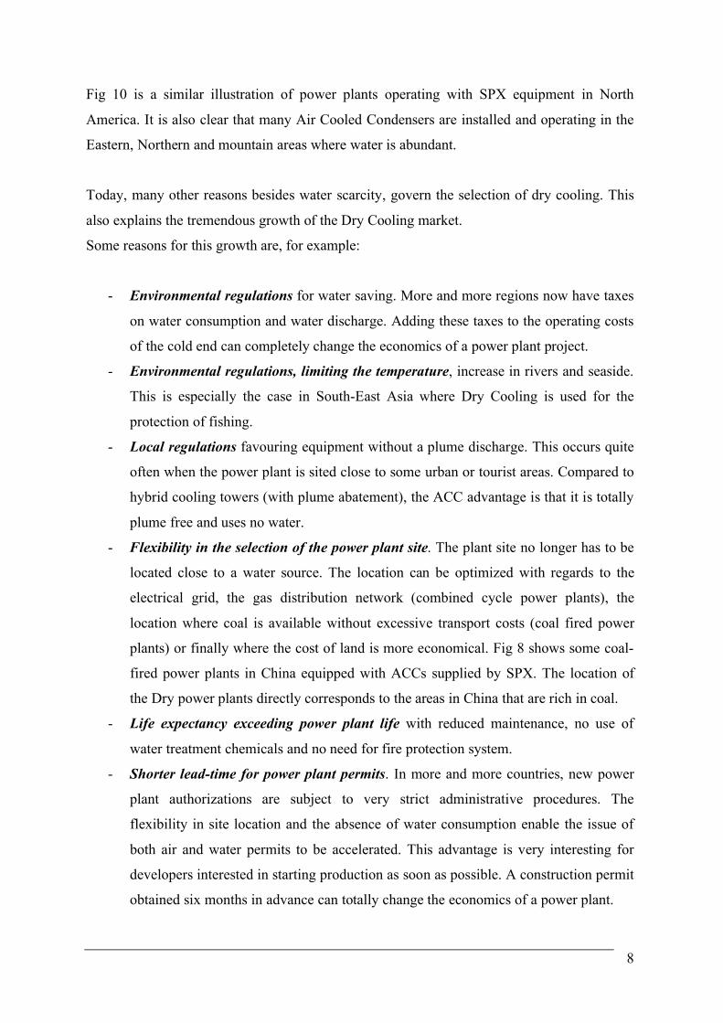
Fig 10 is a similar illustration of power plants operating with SPX equipment in North
America. It is also clear that many Air Cooled Condensers are installed and operating in the
Eastern, Northern and mountain areas where water is abundant.
Today, many other reasons besides water scarcity, govern the selection of dry cooling. This
also explains the tremendous growth of the Dry Cooling market.
Some reasons for this growth are, for example:
- Environmental regulations for water saving. More and more regions now have taxes
on water consumption and water discharge. Adding these taxes to the operating costs
of the cold end can completely change the economics of a power plant project.
- Environmental regulations, limiting the temperature, increase in rivers and seaside.
This is especially the case in South-East Asia where Dry Cooling is used for the
protection of fishing.
- Local regulations favouring equipment without a plume discharge. This occurs quite
often when the power plant is sited close to some urban or tourist areas. Compared to
hybrid cooling towers (with plume abatement), the ACC advantage is that it is totally
plume free and uses no water.
- Flexibility in the selection of the power plant site. The plant site no longer has to be
located close to a water source. The location can be optimized with regards to the
electrical grid, the gas distribution network (combined cycle power plants), the
location where coal is available without excessive transport costs (coal fired power
plants) or finally where the cost of land is more economical. Fig 8 shows some coal-
fired power plants in China equipped with ACCs supplied by SPX. The location of
the Dry power plants directly corresponds to the areas in China that are rich in coal.
- Life expectancy exceeding power plant life with reduced maintenance, no use of
water treatment chemicals and no need for fire protection system.
- Shorter lead-time for power plant permits. In more and more countries, new power
plant authorizations are subject to very strict administrative procedures. The
flexibility in site location and the absence of water consumption enable the issue of
both air and water permits to be accelerated. This advantage is very interesting for
developers interested in starting production as soon as possible. A construction permit
obtained six months in advance can totally change the economics of a power plant.

9
The difference in capital investment or thermal performance between dry cooling and wet
cooling can be easily offset by the above advantages in favour of dry cooling with Air Cooled
Condensers. This is why more and more Dry Cooled power plants are being installed.
Fig 11 – China, some large Coal Fired Power Plants with SPX Air Cooled Condensers
January 2006.
2.4. Present Trends of the Market
Between the 1960s and the 1990s, Europe had a very small market for large or medium size
power plants. Dry cooling was mainly being used in the Middle East, China, South Africa
(ACC or IDCT) and the USA (ACC). As explained above, the market was mainly driven by
the lack of water (coal mine locations, desert or other reasons).
After 1990, the factors driving the use of dry cooled power plants have drastically changed,
as explained above. The world market for Dry Cooling has multiplied by about 20 times in
the last 13 years.
10
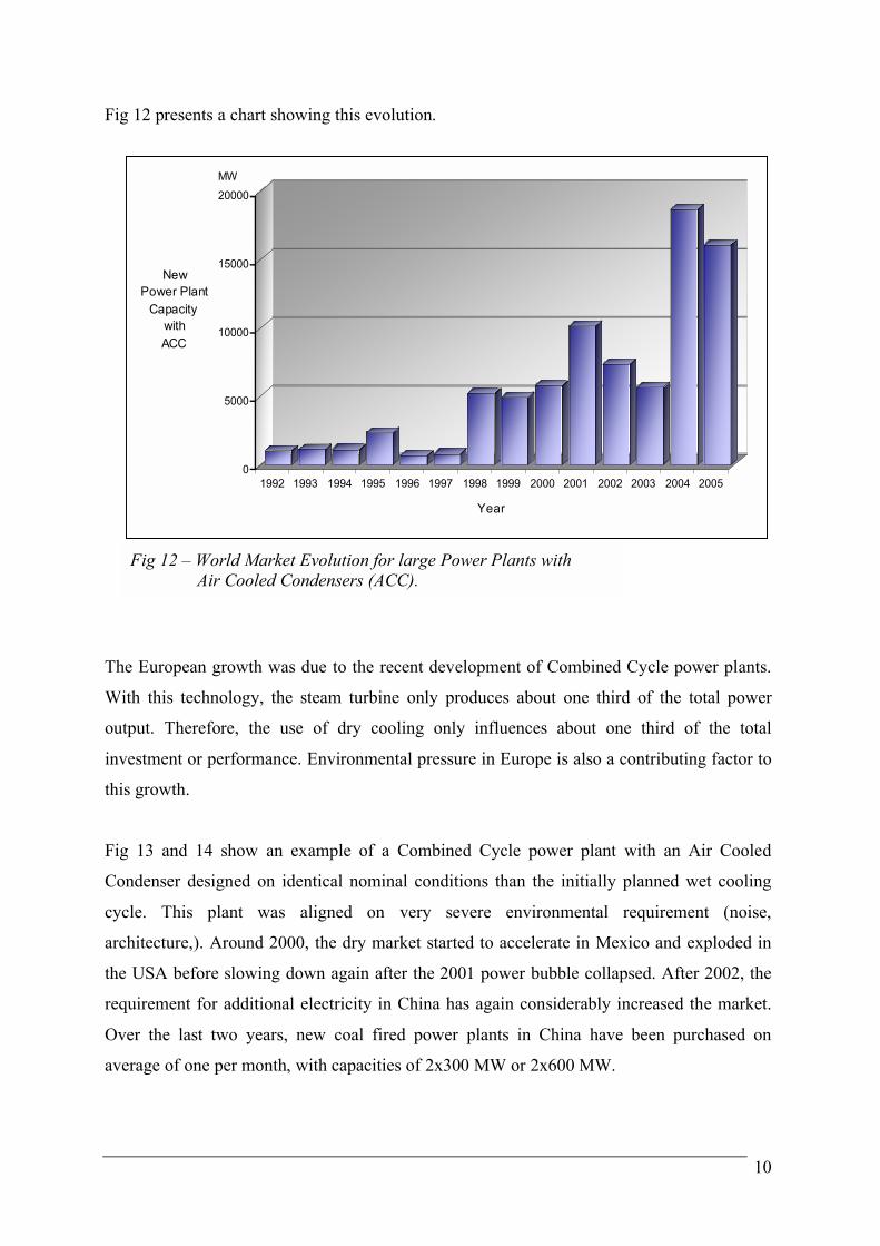
Fig 12 presents a chart showing this evolution.
The European growth was due to the recent development of Combined Cycle power plants.
With this technology, the steam turbine only produces about one third of the total power
output. Therefore, the use of dry cooling only influences about one third of the total
investment or performance. Environmental pressure in Europe is also a contributing factor to
this growth.
Fig 13 and 14 show an example of a Combined Cycle power plant with an Air Cooled
Condenser designed on identical nominal conditions than the initially planned wet cooling
cycle. This plant was aligned on very severe environmental requirement (noise,
architecture,). Around 2000, the dry market started to accelerate in Mexico and exploded in
the USA before slowing down again after the 2001 power bubble collapsed. After 2002, the
requirement for additional electricity in China has again considerably increased the market.
Over the last two years, new coal fired power plants in China have been purchased on
average of one per month, with capacities of 2x300 MW or 2x600 MW.
0
5000
10000
15000
20000
New
Power Plant
Capacity
with
ACC
1992 1993 1994 1995 1996 1997 1998 1999 2000 2001 2002 2003 2004 2005
Year
MW
Fig 12 – World Market Evolution for large Power Plants with
Air Cooled Condensers (ACC).

11
Coal Power Plants in China require very large Air Cooled Condensers as shown in Fig 15 and 16.
In the meantime, Europe continues to be active, but primarily through projects in Italy and
Spain. The largest European Combined Cycle project (1200 MW) is planned to be build in
2007 and will use Dry Cooling with an Air Cooled Condenser.
Fig 13 – Air Cooled Condenser for combined
Cycle Power Plant 500 MW
Apex, Nevada, USA.
Fig 14 – Air Cooled Condenser for combined
Cycle Power Plant 460 MW
Bruges, Belgium.
Fig 15 – Air Cooled Condenser for a Coal
Fired Power Plant
2x300 MW – Zhangshan, China.
Fig 16 – Air Cooled Condenser for a Coal
Fired Power Plant
2x300 MW – Gujiao, China.
12
CHINA
31760 MW
49%
MIDDLE EAST
2400 MW
4%
OTHER ASIA
1720 MW
3%
ROW
1000 MW
2%
OTHER EUROPE
2750 MW
4%
USA
13180 MW
21%
MEXICO
3350 MW
5%
ITALY
5070 MW
8%
SPAIN
2450 MW
4%
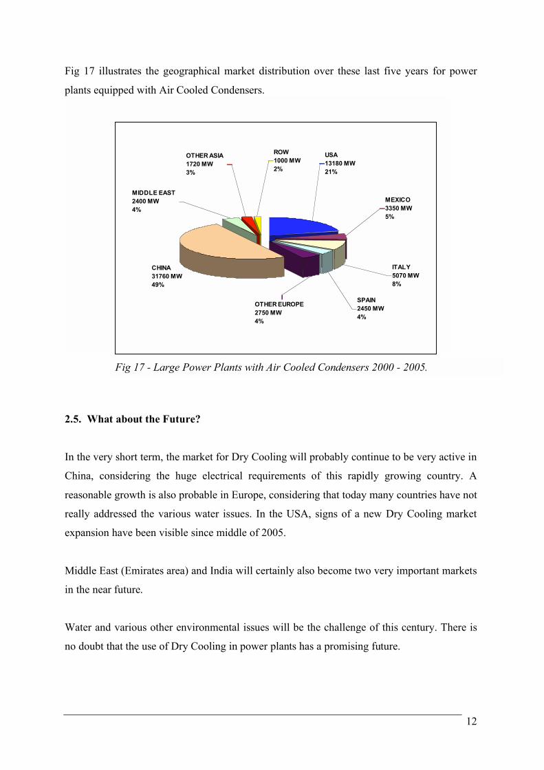
Fig 17 illustrates the geographical market distribution over these last five years for power
plants equipped with Air Cooled Condensers.
2.5. What about the Future?
In the very short term, the market for Dry Cooling will probably continue to be very active in
China, considering the huge electrical requirements of this rapidly growing country. A
reasonable growth is also probable in Europe, considering that today many countries have not
really addressed the various water issues. In the USA, signs of a new Dry Cooling market
expansion have been visible since middle of 2005.
Middle East (Emirates area) and India will certainly also become two very important markets
in the near future.
Water and various other environmental issues will be the challenge of this century. There is
no doubt that the use of Dry Cooling in power plants has a promising future.
Fig 17 - Large Power Plants with Air Cooled Condensers 2000 - 2005.

13
3. AN INNOVATIVE MODULARIZATION CONCEPT
3.1. The Astoria Plant, New York City, USA
One of the most challenging power plant schedules ever attempted in the USA was the
Astoria Energy Project. The challenge was to construct a Combined Cycle Power Plant in
New York City and build it in approximately 24 months
The Astoria Energy Project is a 550 MW gas fired Combined Cycle Power Plant (CCPP). In
a CCPP, electricity is produced using both a combustion turbine and a steam turbine. Waste
heat that exits the combustion turbine is fed to a Heat Recovery Steam Generator (HRSG)
that creates “free” additional steam to drive a steam turbine for a second source of electricity.
Overall efficiencies of a CCPP are significantly higher than other types of power plants and
plant efficiencies can approach 60%.
The Astoria Energy Project uses a 2x1 configuration, requiring two General Electric 7FA gas
turbines, two Alstom HRSGs, an Alstom steam turbine and a SPX Cooling Technologies Air
Cooled Steam Condenser.
The state-of-the-art Astoria Project designed by SHAW Stone & Webster is located on the
East River, in Astoria, Queens, New York City. This plant—which is the largest plant built in
New York City in over 25 years—uses natural gas as the principal fuel, and an ultra low
sulfur distillate fuel oil for approximately 700 hours per year.
Power Plants :
Astoria
Poletti
Ravenswood
Fig 18 – 3 locations in NYC using SPX ACCs
Astoria – Poletti - Ravenswood.

14
The Astoria site is a 23-acre facility located on Steinway Street, next to the world famous
Steinway Piano factory. Every effort was made to use the best available technologies to
achieve the lowest possible air emissions, in fact, lower than those allowed by both New
York State and US Federal Requirements.
Two decisions were made to achieve the lowest possible environmental impact. On the
airside, it was decided to use Selective Catalytic Reduction (SCR) Technology. On the air
and water side, it was decided to use a Dry Cooling System utilizing Air Cooled Condensers.
Although there is an abundant source of water available from the adjacent East River, the
ACCs will not consume or reject any water into the environment, reducing the total plant
requirement for water to only approximately 10% of a power plant using a water-cooled
system.
3.2. The Challenge
Why would anyone want to face the challenge of building a large power plant in NYC, with
limited room, a 24-month schedule and most stringent environmental regulations? Because
New York State demands that 80% of all the electricity used in NYC must be generated
within the five boroughs of the city. Astoria, Queens was selected as an ideal location since:
1. The area has a local high demand for power.
2. The site is located about 1000m from a local substation for transmission.
3. Within a short distance of less than a few city blocks there is an existing natural gas
pipeline.
4. As required, the Astoria site is located within the New York City boundaries.
Using an Air Cooled Condenser at Astoria reduces the need for water and eliminates all the
other variables previously identified in this paper associated with once thru cooling or the use
of a cooling tower. In the USA, 39% of the total water use (277 billion gal/day) is used in
power plant cooling, and 409 billion fish (*) per year are entrained and 60.5 billion fish (*)
per year are impinged by water-cooled power plants. The Astoria ACC will do its part in
protecting the environment power.
(*) "A Comparison of Ecological Impact Of Power Plant Once-Thru, Evaporative and Dry Cooling Systems On Fish Impingement And
Entrainment" - P.A. Henderson & R.M.H. Seaby & J.R. Somes - Pisces Ltd – May 2003

15
3.3. The Astoria Plant
Once it was decided to use Dry Cooling, a plan had to be made to address the schedule,
transport, and any noise that could emanate from the ACC. The plan called for using the East
River, not for a supply of cooling water, but as a means of barge transport. The SPX ACC
was specifically designed to maximize a high degree of factory prefabrication and off site
modularization. The ACC, with 24 modules/fans was preassembled 300 miles south of New
York City in a shipyard located near the Atlantic Ocean in Norfolk, Virginia – see Fig 19 and
20. This off site facility allowed an appropriate time for erection, starting well in advance of
the Astoria site readiness. A warmer climate allowed better productivities during the winter
Virginia erection period, and the remote Virginia site, most importantly, had more then
adequate room for material laydown and lifting equipment.
Fig 19 – Pre-assembly of the twin SPX
modules – Norfolk, Virginia.
Fig 20 – Steam manifolds assembled on the
SPX modules in Norfolk, Virginia.
Norforlk
N.Y
Fig 22 – Ocean transport with two barges
together. Fig 21 – Map showing transfer route from
Norfolk to New York City.
16
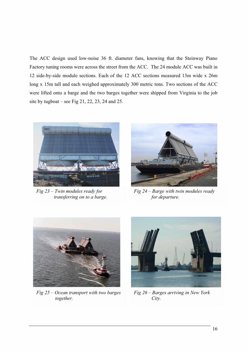
The ACC design used low-noise 36 ft. diameter fans, knowing that the Steinway Piano
Factory tuning rooms were across the street from the ACC. The 24 module ACC was built in
12 side-by-side module sections. Each of the 12 ACC sections measured 13m wide x 26m
long x 15m tall and each weighed approximately 300 metric tons. Two sections of the ACC
were lifted onto a barge and the two barges together were shipped from Virginia to the job
site by tugboat – see Fig 21, 22, 23, 24 and 25.
Fig 23 – Twin modules ready for
transferring on to a barge.
Fig 24 – Barge with twin modules ready
for departure.
Fig 25 – Ocean transport with two barges
together.
Fig 26 – Barges arriving in New York
City.
17
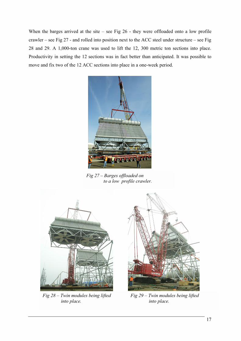
When the barges arrived at the site – see Fig 26 - they were offloaded onto a low profile
crawler – see Fig 27 - and rolled into position next to the ACC steel under structure – see Fig
28 and 29. A 1,000-ton crane was used to lift the 12, 300 metric ton sections into place.
Productivity in setting the 12 sections was in fact better than anticipated. It was possible to
move and fix two of the 12 ACC sections into place in a one-week period.
Fig 27 – Barges offloaded on
to a low profile crawler.
Fig 28 – Twin modules being lifted
into place.
Fig 29 – Twin modules being lifted
into place.

18
3.4. The Astoria Results
The ACC was assembled ahead of schedule, see Fig 30 and 31. Only 9 months after award,
the ACC sections started to arrive at the Astoria site for final assembly. The steam ductwork,
which was also preassembled in Virginia, arrived circumferentially whole in maximum barge
lengths for final assembly at site. In all, 80% of the total man-hours required to assemble the
ACC was done in Norfolk, Virginia.
If similar Dry Cooled power plants nearby Astoria are any indication of the time required to
assemble an ACC in the New York City, the ACC advanced pre-modularization concept
easily saved 50% of the schedule for the ACC erection.
The plan worked out by SHAW Stone & Webster, which also included shipping the 2000
metric ton HRSG in one piece to site by barge, was successful. Proper planning allowed the
plant to start up on time with a construction time of approximately 24 months.
This innovative project was a huge challenge and a total success for SPX Cooling
Technologies.
Fig 30 – Final assembly of the SPX
Air Cooled Condenser.
Fig 31 – Final assembly of the SPX
Air Cooled Condenser.