DRV-GEN5 RICOH GEN5 PRINTHEAD DRIVER BOARD HARDWARE USER … · 2017-01-31 · DRV-GEN5 – Ricoh...
10
DRV-GEN5 – RICOH GEN5 PRINTHEAD DRIVER BOARD HARDWARE USER GUIDE 30.11.2016 Version 1.4
Transcript of DRV-GEN5 RICOH GEN5 PRINTHEAD DRIVER BOARD HARDWARE USER … · 2017-01-31 · DRV-GEN5 – Ricoh...
DRV-GEN5 – RICOH GEN5 PRINTHEAD DRIVER BOARD
HARDWARE USER GUIDE
30.11.2016
Version 1.4
DRV-GEN5 – Ricoh Gen5 Printhead Driver Board Hardware User Guide
www.aewa.de 2
Table of Contents 1 Overview ...................................................................................................................................................... 3
2 Board Components ................................................................................................................................... 4
2.1 .... Printhead Connector (J1) ...............................................................................................................................5
2.2 .... Optical Interface (SFP1) .................................................................................................................................5
2.3 .... Power Input Connector (J11) .......................................................................................................................5
2.4 .... FAN Connector (J6) ...........................................................................................................................................6
2.5 .... LEDs .........................................................................................................................................................................6
2.6 .... JTAG Connector (J2) ..........................................................................................................................................7
2.7 .... Test Connector (J4) ...........................................................................................................................................7
2.8 .... Jumper (J3) ............................................................................................................................................................7
3 Mechanical Dimensions .......................................................................................................................... 8
4 Connectors and Cables ............................................................................................................................ 9
5 Ordering Information ........................................................................................................................... 10
DRV-GEN5 – Ricoh Gen5 Printhead Driver Board Hardware User Guide
www.aewa.de 3
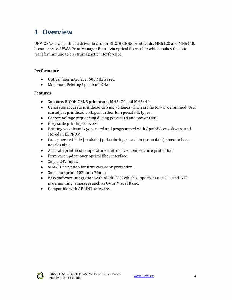
1 Overview
DRV-GEN5 is a printhead driver board for RICOH GEN5 printheads, MH5420 and MH5440.
It connects to AEWA Print Manager Board via optical fiber cable which makes the data
transfer immune to electromagnetic interference.
Performance
Optical fiber interface: 600 Mbits/sec.
Maximum Printing Speed: 60 KHz
Features
Supports RICOH GEN5 printheads, MH5420 and MH5440.
Generates accurate printhead driving voltages which are factory programmed. User
can adjust printhead voltages further for special ink types.
Correct voltage sequencing during power ON and power OFF.
Grey scale printing, 8 levels.
Printing waveform is generated and programmed with ApmbWave software and
stored in EEPROM.
Can generate tickle (or shake) pulse during zero data (or no data) phase to keep nozzles alive.
Accurate printhead temperature control, over temperature protection.
Firmware update over optical fiber interface.
Single 24V input.
SHA-1 Encryption for firmware copy protection.
Small footprint, 102mm x 76mm.
Easy software integration with APMB SDK which supports native C++ and .NET
programming languages such as C# or Visual Basic.
Compatible with APRINT software.
DRV-GEN5 – Ricoh Gen5 Printhead Driver Board Hardware User Guide
www.aewa.de 4
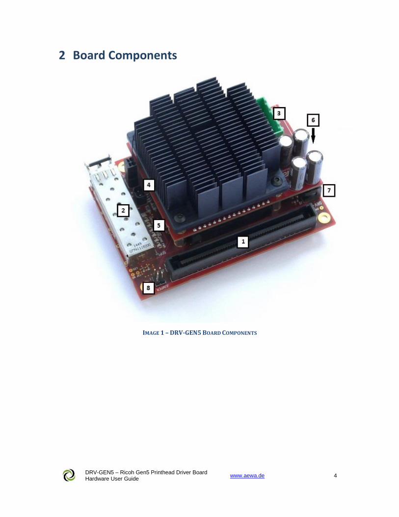
2 Board Components
IMAGE 1 – DRV-GEN5 BOARD COMPONENTS
DRV-GEN5 – Ricoh Gen5 Printhead Driver Board Hardware User Guide
www.aewa.de 5
2.1 Printhead Connector (J1)
DRV-GEN5 connects to the Ricoh Gen5 printhead through J1 connector. It mates directly
with the Adapter PCB which is delivered with the printhead.
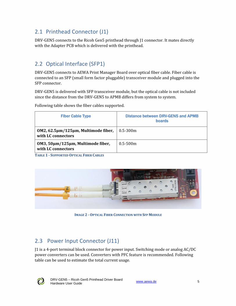
2.2 Optical Interface (SFP1)
DRV-GEN5 connects to AEWA Print Manager Board over optical fiber cable. Fiber cable is
connected to an SFP (small form factor pluggable) transceiver module and plugged into the
SFP connector.
DRV-GEN5 is delivered with SFP transceiver module, but the optical cable is not included
since the distance from the DRV-GEN5 to APMB differs from system to system.
Following table shows the fiber cables supported.
Fiber Cable Type Distance between DRV-GEN5 and APMB
boards
OM2, 62.5μm/125μm, Multimode fiber, with LC connectors
0.5-300m
OM3, 50μm/125μm, Multimode fiber, with LC connectors
0.5-500m
TABLE 1 - SUPPORTED OPTICAL FIBER CABLES
IMAGE 2 - OPTICAL FIBER CONNECTION WITH SFP MODULE
2.3 Power Input Connector (J11)
J1 is a 4-port terminal block connector for power input. Switching mode or analog AC/DC
power converters can be used. Converters with PFC feature is recommended. Following
table can be used to estimate the total current usage.
DRV-GEN5 – Ricoh Gen5 Printhead Driver Board Hardware User Guide
www.aewa.de 6
Parameter Value
Input Voltage 24V (23.5 – 24.5V)
Max. current consumption, DRV-GEN5 board + Gen 5 printhead, all nozzles firing with maximum speed
1.7A @24V
Max. current consumption, printhead heater 368mA @24V
TABLE 2 -INPUT POWER SPECIFICATIONS
2.4 FAN Connector (J6)
If desired, DRV-GEN5 can be delivered with a 60mm axial fan attached to the Heat-Sink. J2
connector supplies power to the FAN.
FAN may be required for applications with high image coverage such as negative printing.
Fan is only switched ON if the temperature of the Heat-sink exceeds a predefined value.
2.5 LEDs
There are 7 diagnostics LEDs on the DRV-GEN5 PCB.
PWR LED is connected to the 3.3V voltage rail. It is ON when board power is OK.
DONE LED is ON when FPGA firmware is loaded correctly, otherwise none of the features of
DRV-GEN5 is available.
FIRE LED is ON when printhead nozzles are active and printing. It switches OFF when
printing is stopped.
RX LED is ON when AEWA Print Manager Board is sending printing data to DRV-GEN5
board, otherwise it is OFF.
TEST LED is OFF when the image data stream is counting data, otherwise it is ON. This LED
is used for internal tests by AEWA.
ERR1 LED is OFF when SHA-1 Encryption keys programmed into the device is correct. If
this LED is ON, complete functions of the DRV-GEN5 board are disabled.
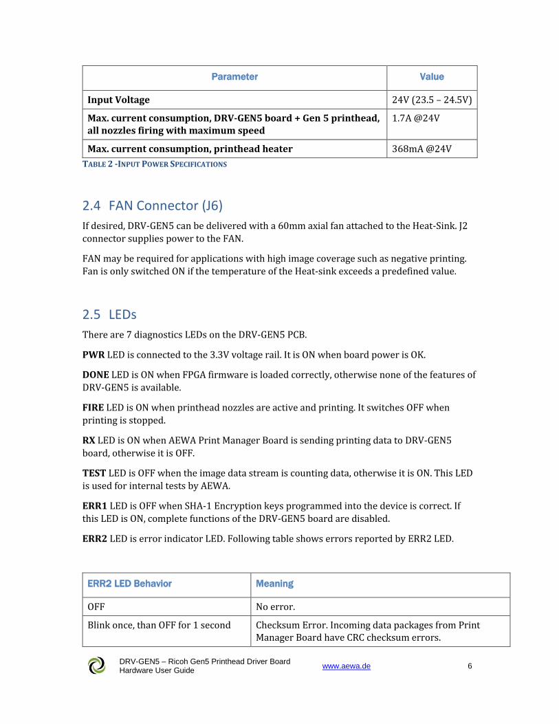
ERR2 LED is error indicator LED. Following table shows errors reported by ERR2 LED.
ERR2 LED Behavior Meaning
OFF No error.
Blink once, than OFF for 1 second Checksum Error. Incoming data packages from Print Manager Board have CRC checksum errors.
DRV-GEN5 – Ricoh Gen5 Printhead Driver Board Hardware User Guide
www.aewa.de 7
Blink 2 times, than OFF for 1 second Data packaging error. Incoming data packages from Print Manager Board have wrong number of bytes.
Blink 3 times, than OFF for 1 second Speed error. Printing speed is too high for the printhead with the current waveform and bits per pixels setting.
Blink 4 times, than OFF for 1 second Waveform error. Either no waveform is loaded or the loaded waveform has errors.
Blink 5 times, than OFF for 1 second No meaning. Reserved for future use.
Blink 6 times, than OFF for 1 second Printhead voltages are switched off due to an over temperature or voltage error condition.
Blink 7 times, than OFF for 1 second No meaning. Reserved for future use.
TABLE 3 –TEST LED FUNCTION
Same errors can also be read by APMB software. More error types might be added in future
with firmware updates.
2.6 JTAG Connector (J2)
This connector is for internal use by AEWA for testing, debugging and updating the
firmware. DRV-GEN5 firmware can also be updated over optical interface using ApmbDiag
software.
2.7 Test Connector (J4)
J4 is test header for internal use by AEWA.
2.8 Jumper (J3)
DRV-GEN5 has a 2-port jumper on J3. They are marked as 0 and 1 on the PCB. See
“Mechanical Dimensions” section for the correct orientation of jumpers.
Following table shows the function of jumpers.
Index Function
Jumper 0 No function. Reserved for future use.
Jumper 1 No function. Reserved for future use.
TABLE 4 – JUMPER FUNCTION TABLE
DRV-GEN5 – Ricoh Gen5 Printhead Driver Board Hardware User Guide
www.aewa.de 8
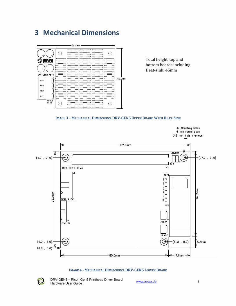
3 Mechanical Dimensions
IMAGE 3 – MECHANICAL DIMENSIONS, DRV-GEN5 UPPER BOARD WITH HEAT-SINK
IMAGE 4 - MECHANICAL DIMENSIONS, DRV-GEN5 LOWER BOARD
Total height, top and
bottom boards including
Heat-sink: 45mm
DRV-GEN5 – Ricoh Gen5 Printhead Driver Board Hardware User Guide
www.aewa.de 9
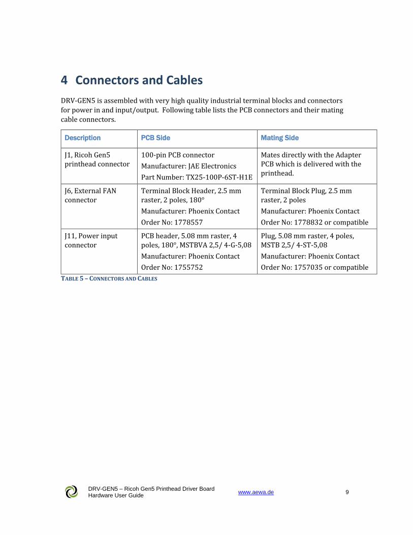
4 Connectors and Cables
DRV-GEN5 is assembled with very high quality industrial terminal blocks and connectors
for power in and input/output. Following table lists the PCB connectors and their mating
cable connectors.
Description PCB Side Mating Side
J1, Ricoh Gen5 printhead connector
100-pin PCB connector
Manufacturer: JAE Electronics
Part Number: TX25-100P-6ST-H1E
Mates directly with the Adapter PCB which is delivered with the printhead.
J6, External FAN connector
Terminal Block Header, 2.5 mm raster, 2 poles, 180°
Manufacturer: Phoenix Contact
Order No: 1778557
Terminal Block Plug, 2.5 mm raster, 2 poles
Manufacturer: Phoenix Contact
Order No: 1778832 or compatible
J11, Power input connector
PCB header, 5.08 mm raster, 4 poles, 180°, MSTBVA 2,5/ 4-G-5,08
Manufacturer: Phoenix Contact
Order No: 1755752
Plug, 5.08 mm raster, 4 poles, MSTB 2,5/ 4-ST-5,08
Manufacturer: Phoenix Contact
Order No: 1757035 or compatible
TABLE 5 – CONNECTORS AND CABLES
DRV-GEN5 – Ricoh Gen5 Printhead Driver Board Hardware User Guide
www.aewa.de 10
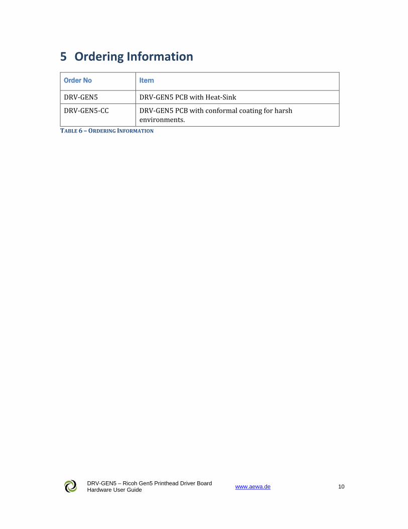
5 Ordering Information
Order No Item
DRV-GEN5 DRV-GEN5 PCB with Heat-Sink
DRV-GEN5-CC DRV-GEN5 PCB with conformal coating for harsh environments.
TABLE 6 – ORDERING INFORMATION