Drum Pump Recirculation Kit Part #30032 - Trico Corporation...The Trico Drum Pump Recirculation Kit...
7
1235 Hickory Street | Pewaukee, WI 53137 For Customer Support: (800) 558-7008 61443 Drum Pump Recirculation Kit Part #30032 Setup and Operating Instructions Rev A, AUG 2019
Transcript of Drum Pump Recirculation Kit Part #30032 - Trico Corporation...The Trico Drum Pump Recirculation Kit...

1235 Hickory Street | Pewaukee, WI 53137
For Customer Support: (800) 558-7008
61443
Drum Pump Recirculation Kit Part #30032
Setup and Operating Instructions
Rev A, AUG 2019
1235 Hickory Street | Pewaukee, WI 53137
For Customer Support: (800) 558-7008
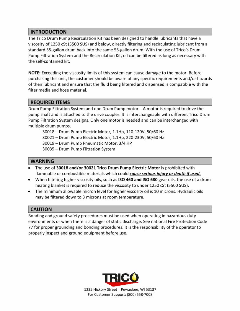
INTRODUCTION The Trico Drum Pump Recirculation Kit has been designed to handle lubricants that have a viscosity of 1250 cSt (5500 SUS) and below, directly filtering and recirculating lubricant from a standard 55-gallon drum back into the same 55-gallon drum. With the use of Trico’s Drum Pump Filtration System and the Recirculation Kit, oil can be filtered as long as necessary with the self-contained kit. NOTE: Exceeding the viscosity limits of this system can cause damage to the motor. Before purchasing this unit, the customer should be aware of any specific requirements and/or hazards of their lubricant and ensure that the fluid being filtered and dispensed is compatible with the filter media and hose material. REQUIRED ITEMS
Drum Pump Filtration System and one Drum Pump motor – A motor is required to drive the pump shaft and is attached to the drive coupler. It is interchangeable with different Trico Drum Pump Filtration System designs. Only one motor is needed and can be interchanged with multiple drum pumps.
30018 – Drum Pump Electric Motor, 1.1Hp, 110-120V, 50/60 Hz 30021 – Drum Pump Electric Motor, 1.1Hp, 220-230V, 50/60 Hz 30019 – Drum Pump Pneumatic Motor, 3/4 HP 30035 – Drum Pump Filtration System
WARNING • The use of 30018 and/or 30021 Trico Drum Pump Electric Motor is prohibited with
flammable or combustible materials which could cause serious injury or death if used. • When filtering higher viscosity oils, such as ISO 460 and ISO 680 gear oils, the use of a drum
heating blanket is required to reduce the viscosity to under 1250 cSt (5500 SUS). • The minimum allowable micron level for higher viscosity oil is 10 microns. Hydraulic oils
may be filtered down to 3 microns at room temperature. CAUTION
Bonding and ground safety procedures must be used when operating in hazardous duty environments or when there is a danger of static discharge. See national Fire Protection Code 77 for proper grounding and bonding procedures. It is the responsibility of the operator to properly inspect and ground equipment before use.
1235 Hickory Street | Pewaukee, WI 53137
For Customer Support: (800) 558-7008
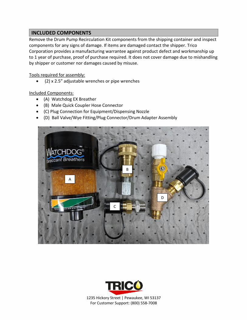
INCLUDED COMPONENTS Remove the Drum Pump Recirculation Kit components from the shipping container and inspect components for any signs of damage. If items are damaged contact the shipper. Trico Corporation provides a manufacturing warrantee against product defect and workmanship up to 1 year of purchase, proof of purchase required. It does not cover damage due to mishandling by shipper or customer nor damages caused by misuse. Tools required for assembly:
• (2) x 2.5” adjustable wrenches or pipe wrenches Included Components:
• (A) Watchdog EX Breather • (B) Male Quick Coupler Hose Connector • (C) Plug Connection for Equipment/Dispensing Nozzle • (D) Ball Valve/Wye Fitting/Plug Connector/Drum Adapter Assembly
A
B
C
D
1235 Hickory Street; Pewaukee, WI 53137
For Customer Support: 1-800-558-7008
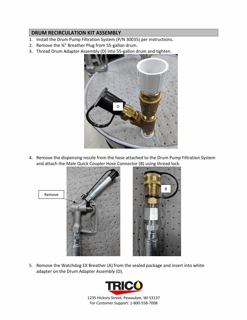
DRUM RECIRCULATION KIT ASSEMBLY 1. Install the Drum Pump Filtration System (P/N 30035) per instructions. 2. Remove the ¾” Breather Plug from 55-gallon drum. 3. Thread Drum Adapter Assembly (D) into 55-gallon drum and tighten.
4. Remove the dispensing nozzle from the hose attached to the Drum Pump Filtration System and attach the Male Quick Coupler Hose Connector (B) using thread lock.
5. Remove the Watchdog EX Breather (A) from the sealed package and insert into white adapter on the Drum Adapter Assembly (D).
D
B Remove
1235 Hickory Street; Pewaukee, WI 53137
For Customer Support: 1-800-558-7008
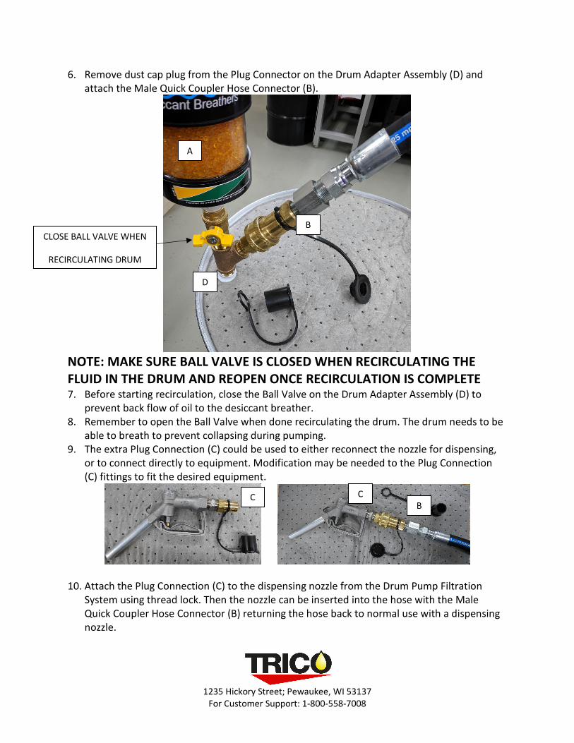
6. Remove dust cap plug from the Plug Connector on the Drum Adapter Assembly (D) and attach the Male Quick Coupler Hose Connector (B).
NOTE: MAKE SURE BALL VALVE IS CLOSED WHEN RECIRCULATING THE FLUID IN THE DRUM AND REOPEN ONCE RECIRCULATION IS COMPLETE 7. Before starting recirculation, close the Ball Valve on the Drum Adapter Assembly (D) to
prevent back flow of oil to the desiccant breather. 8. Remember to open the Ball Valve when done recirculating the drum. The drum needs to be
able to breath to prevent collapsing during pumping. 9. The extra Plug Connection (C) could be used to either reconnect the nozzle for dispensing,
or to connect directly to equipment. Modification may be needed to the Plug Connection (C) fittings to fit the desired equipment.
10. Attach the Plug Connection (C) to the dispensing nozzle from the Drum Pump Filtration
System using thread lock. Then the nozzle can be inserted into the hose with the Male Quick Coupler Hose Connector (B) returning the hose back to normal use with a dispensing nozzle.
A
B
D
CLOSE BALL VALVE WHEN
RECIRCULATING DRUM
C C B
1235 Hickory Street; Pewaukee, WI 53137
For Customer Support: 1-800-558-7008
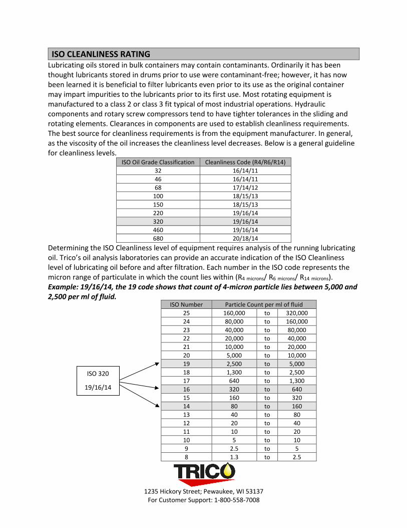
ISO CLEANLINESS RATING Lubricating oils stored in bulk containers may contain contaminants. Ordinarily it has been thought lubricants stored in drums prior to use were contaminant-free; however, it has now been learned it is beneficial to filter lubricants even prior to its use as the original container may impart impurities to the lubricants prior to its first use. Most rotating equipment is manufactured to a class 2 or class 3 fit typical of most industrial operations. Hydraulic components and rotary screw compressors tend to have tighter tolerances in the sliding and rotating elements. Clearances in components are used to establish cleanliness requirements. The best source for cleanliness requirements is from the equipment manufacturer. In general, as the viscosity of the oil increases the cleanliness level decreases. Below is a general guideline for cleanliness levels.
ISO Oil Grade Classification Cleanliness Code (R4/R6/R14) 32 16/14/11 46 16/14/11 68 17/14/12
100 18/15/13 150 18/15/13 220 19/16/14 320 19/16/14 460 19/16/14 680 20/18/14
Determining the ISO Cleanliness level of equipment requires analysis of the running lubricating oil. Trico’s oil analysis laboratories can provide an accurate indication of the ISO Cleanliness level of lubricating oil before and after filtration. Each number in the ISO code represents the micron range of particulate in which the count lies within (R4 microns/ R6 microns/ R14 microns). Example: 19/16/14, the 19 code shows that count of 4-micron particle lies between 5,000 and 2,500 per ml of fluid.
ISO Number Particle Count per ml of fluid 25 160,000 to 320,000 24 80,000 to 160,000 23 40,000 to 80,000 22 20,000 to 40,000 21 10,000 to 20,000 20 5,000 to 10,000 19 2,500 to 5,000 18 1,300 to 2,500 17 640 to 1,300 16 320 to 640 15 160 to 320 14 80 to 160 13 40 to 80 12 20 to 40 11 10 to 20 10 5 to 10 9 2.5 to 5 8 1.3 to 2.5
ISO 320
19/16/14
1235 Hickory Street; Pewaukee, WI 53137
For Customer Support: 1-800-558-7008
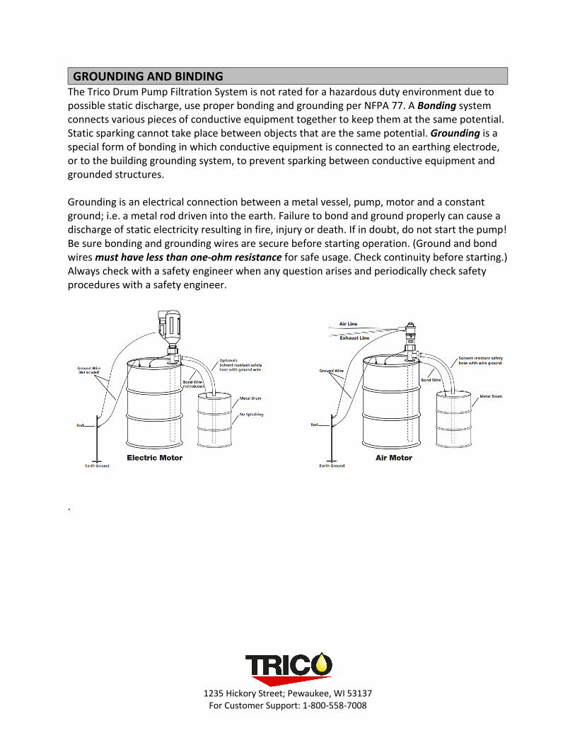
GROUNDING AND BINDING The Trico Drum Pump Filtration System is not rated for a hazardous duty environment due to possible static discharge, use proper bonding and grounding per NFPA 77. A Bonding system connects various pieces of conductive equipment together to keep them at the same potential. Static sparking cannot take place between objects that are the same potential. Grounding is a special form of bonding in which conductive equipment is connected to an earthing electrode, or to the building grounding system, to prevent sparking between conductive equipment and grounded structures.
Grounding is an electrical connection between a metal vessel, pump, motor and a constant ground; i.e. a metal rod driven into the earth. Failure to bond and ground properly can cause a discharge of static electricity resulting in fire, injury or death. If in doubt, do not start the pump! Be sure bonding and grounding wires are secure before starting operation. (Ground and bond wires must have less than one-ohm resistance for safe usage. Check continuity before starting.) Always check with a safety engineer when any question arises and periodically check safety procedures with a safety engineer.
.