Druck DPI 610/615 - Instrumart · PDF fileTypical Calibration Set-up (Pressure to Voltage) ......
90
Druck DPI 610/615 Portable Pressure Calibrator Series User manual - K0415 GE Sensing & Inspection Technologies
Transcript of Druck DPI 610/615 - Instrumart · PDF fileTypical Calibration Set-up (Pressure to Voltage) ......

Druck DPI 610/615Portable Pressure Calibrator Series
User manual - K0415
GE Sensing & Inspection Technologies


EnglishTo select the manual in an available language go to:
//www.gesensing.com/toolsupport/manuals.htmFrançaisPour choisir le manuel dans une langue disponible, accédez à :
//www.gesensing.com/toolsupport/manuals.htmDeutschUm das Handbuch in einer vorhandenen Sprache auszuwählen, gehen Sie zu:
//www.gesensing.com/toolsupport/manuals.htmItalianoPer scaricare il manuale in una delle lingue disponibili consultare la pagina:
//www.gesensing.com/toolsupport/manuals.htmEspañolPara seleccionar el manual en uno de los idiomas disponibles vaya a:
//www.gesensing.com/toolsupport/manuals.htmPortuguêsPara selecionar o manual em uma língua disponível vá:
//www.gesensing.com/toolsupport/manuals.htmPolskiAby wybrać podręcznik w dostępnym języku, przejdź do strony:
//www.gesensing.com/toolsupport/manuals.htmЯзык Для выбора руководства на имеющемся языке зайдите на web-сайт
//www.gesensing.com/toolsupport/manuals.htm语言选择手册的语言,请访问:
//www.gesensing.com/toolsupport/manuals.htm言語利用可能な言語のマニュアルを選択するには次のサイトへアクセスしてください :
//www.gesensing.com/toolsupport/manuals.htm
i K0415 Issue No. 2

Safety
The manufacturer has designed this equipment to be safe when operated using the procedures detailed in this manual. Do not use this equipment for any other purpose than that stated.This publication contains operating and safety instructions that must be followed to ensure safe operation and to maintain the equipment in a safe condition. The safety instructions are either warnings or cautions issued to protect the user and the equipment from injury or damage.Use suitably qualified * technicians and good engineering practice for all procedures in this publication.PressureDo not apply pressures greater than the safe working pressure to this equipment. MaintenanceThe equipment must be maintained using the procedures in this publication. Further manufacturer’s procedures should be carried out by authorized service agents or the manufacturer’s service departments.
www.gesensing.com
For technical advice contact the manufacturer.
* A qualified technician must have the necessary technical knowledge, documentation, special test equipment and tools to carry out the required work on this equipment.
Symbols
This equipment meets the requirements of all relevant European safety directives. The equipment carries the CE mark.
This symbol, on the instrument, indicates that the user should refer to the user manual. This symbol, in this manual, indicates a hazardous operation.
This symbol, on the instrument, indicates do not throw-away in domestic bin, hazardous material, dispose correctly in accordance with local regulations.
K0415 Issue No. 2 ii

SpecificationSafe working pressure
20 bar range (300 psi) 1.75 x full-scale350 bar range (5000 psi) 1.2 x full-scale400 bar range (6000 psi) 1.5 x full-scaleAll other ranges 2 x full-scale
AccuracyCombined non-linearity, hysteresis and repeatability
±70 mbar range (2 inHg) 0.05% F.S.up to ±150 mbar (4.4 inHg) 0.05% span200 mbar to 20 bar (3 psi to 300 psi) [Calibrator]): 0.025% F.S.35 bar to 700 bar (500 psi to 10000 psi) [Indicator] 0.025% F.S.70 bar to 400 bar (1000 psi to 6000 psi) [Hydraulic] 0.025% F.S.
Pressure RangesRefer to the pressure range matrix in the data sheet.
Temperature Effects±0.004% of reading/°C (averaged over -10° to +40°C w.r.t. 20°C)±0.002% of reading/°F (averaged over +14° to 104°F w.r.t. 68°F)
Power supplyBatteries 6 x 1.5 V C cells, alkaline (up to 60 hours nominal use at 20°C)Rechargeable NiCad battery pack (20 hours nominal use) supplied with charger/adaptor, supplies power to instrument while charging batteries.
Voltage InputsRange: ±50VAccuracy ±0.05% rdg, ±0.004% F.S.Resolution 100µV max
Voltage OutputsRange: ±10VAccuracy ±0.1% Load 10mARange: ±24VAccuracy ±5%Load 26mA
Current InputsRange: ±55mAAccuracy ±0.05% rdg, ±0.004% F.S.Resolution 1µA max
Current OutputRange: 24mAAccuracy ±0.05% rdg, ±0.01% F.S.Resolution 1µA max
iii K0415 Issue No. 2
Specification (contd.)
DisplaySize: 60 x 60 mm (2.36” x 2.36”) LCD GraphicsReading ±99999, update rate 2 readings/sec
EnvironmentOperating Temperature: -10°C to 50°C (+14°F to 122°F) Calibrated Temperature: -10°C to 40°C (+14°F to 104°F)Storage Temperature: -20°C to 60°C (-4°F to 140°F)Calibration Temperature: 21°C ±2°C (70°F ±4°F)
SealingSealed to IP54 (NEMA 4)
PhysicalSize: 300 x 170 x 140 mm (11.8” x 6.7” x 5.5”)Weight: 3 kg (6.6lb)
K0415 Issue No. 2 iv
IntroductionGeneralDescription of Procedures 1
Summary of FunctionsUsing the Guide 2
OPERATOR CONTROLS 3DISPLAY 3HARD KEY FUNCTIONS 4SOFT KEYS 5CURSOR KEYS 5ELECTRICAL CONNECTIONS 6
Getting Started Fitting Batteries 7 Switching On 7Change Pressure Units 8Voltage and Current Measurement 8Typical Calibration Set-up (Pressure to Voltage) 9Zero Display Reading 9
Task SelectionTask Key 10 Using Task Functions 10Set Units 10Set 24 Volts 10Cal Mode (DPI 615 versions only) 11Basic Mode (Task BASIC) 11
Taking MeasurementsPressure Transmitter (P-I) Task 12Voltage Output Pressure Transmitter (P-V) Task 12Pressure Converter (P-P) Task 13Current to Pressure Converter (I-P) Task 14Pressure Switch Test (P-Switch) Task 14Pressure Switch Testing with Contact Resistance Measurement 15Pressure to Display (P-Display) Task 16Leak Test (Leak Test) Task 17Transmitter Simulator (TX SIM) Task 18Relief Valve Test (REL VALVE) Task 19
v K0415 Issue No. 2

Advanced TaskGeneral 20Select Input 20Ambient Temperature Measurement 20Process Functions 21Tare Process Function 22Min/Max Process Function 23Filter Process Function 23Flow Function 24% Span 24Select Output 25
Electrical Outputs (Loop Power) 25mA Step 26mA Ramp 27mA Value 2824 Volt 28Define New Task 29Clear Task 29
Memory OperationsSaving Display or Data Log 30Store Operations (Screen Snapshots) 30Recalling Stored Data (Screen Snapshots) 30Datalog Operations 31
Auto Log (Timer) 31Manual Logging 31
Recall Data Log Files 32Uploading Data Log Files 33Delete Data Log and Procedure Files 33Downloading Procedure Files (DPI 615 versions only) 34Running Procedure Files (DPI 615 versions only) 35Recalling Data Files 36
Using Set-upGeneral 37Store Mode 37Contrast 37Settings - Select Set-up Option 38
Units 38Define Special Units 38Language 39RS232 39Powerdown 40
K0415 Issue No. 2 vi

Calibration 40Date and Time (Real Time Clock) 41
Date Format 41Set Date 41Set Time 41
Backlight 42 Calibration
General 43Calibration Check 43Calibration Adjustment 43General Procedures 44Using The Calibration Menu 45Change PIN 45Pressure 46Voltage Input Range (5 Volts) 47Voltage Input Range (50 Volts) 49Current Input Range (55 mA) 51Current Output Range (24 mA) 53Temperature 56External Pressure Range 57Add External Sensor 58
Hydraulic Calibrator VersionsIntroduction 61Safety Instructions 62Preparation for Use 62Bleeding the System 63Draining the Hydraulic Fluid 64Flushing, Replenishing or Changing the Hydraulic Fluid 65
Low Pressure Calibrator VersionsIntroduction 69Preparation for Use Low Volume Systems 70Method of Testing with Low Volume Systems 70Preparation for Use Larger Volume Systems 72Method of Testing with Larger Volume Systems 74Calibration 75Calibrate Internal Pressure Range 75
Appendix 1 - Datalog File ExampleTypical Uploaded Datalog File (DPI 610) 79Typical Uploaded Procedure Data File (DPI 615) 80
vii K0415 Issue No. 2

K0415 Issue No. 2 viii

INTRODUCTION Summary of Functions
GeneralThe versions of the DPI 610 and DPI 615 instruments are: pneumatic indicator, pneumatic calibrator, hydraulic calibrator and low pressure pneumatic calibrator. All instruments measure and display pneumatic and hydraulic pressure applied to the test port or to an externally connected pressure sensor. Pressure measurement can be absolute, gauge and sealed gauge and in ranges from 2.5 mbar to 700 bar (1.0 inH2O to 10000 psi).The calibrator versions of this instrument contain pneumatic or hydraulic pressure generation components to produce pneumatic pressure ranges between -1 to 20 bar (-14.5 psi to 300 psi) and hydraulic pressure ranges up to 400 bar (6000 psi).The electrical connections, on the front of the instrument, enable the instrument to measure ±50 volts d.c. and ±55 mA and produce 10 volts d.c. or 24 volts d.c. and a maximum of 24 mA. An integral sensor provides measurement of ambient temperature. Additional sensors (option B1) connect to an external connector and extend the pressure measurement range and include differential pressure measurement. The instrument has an RS232 connector to enable uploading of test data to a compatible documenting system. The DPI 615 has the ability to download, from a PC, pre-defined calibration and test routines. Six alkaline C size batteries or (option A) rechargeable batteries with a charger/adaptor, power the instrument.Important NoticeZinc-carbon and zinc-chloride cells should NOT be used in this instrument.
Use only the battery types as shown in the table on page 7.
Description of ProceduresIn the procedures outlined in this user guide, hard (fixed function) and soft (variable function) key operations are shown in bold type (e.g.) TASK and F1. These statements mean press the TASK key and press the F1 key. Soft key operations can be allocated to both the F1 and F2 keys. Where a specific soft function is referred to it is written in bold italics (e.g.) PROCESS.This instrument has a number of operating modes that are described in a simplified form in the following sections. Diagrams accompanying the procedures give typical selection sequences and shaded controls indicate that this control key should be pressed in the appropriate sequence. Diagrams should be read from left to right, top to bottom where appropriate. A shaded display soft box indicates that the function key immediately below that soft box should be pressed (either F1 for the left hand soft box or F2 for the right).
In the above diagram the following key sequence is indicated.(a) Press the F2 key (the key immediately below the PRESSURE UNITS soft box).(b) Use the Up and Down cursor keys (only) to select the required option. (If all keys
shaded, use all these keys to select or enter data).(c) Press the ENTER key.
1 K0415 Issue No. 2
INTRODUCTION Summary of Functions
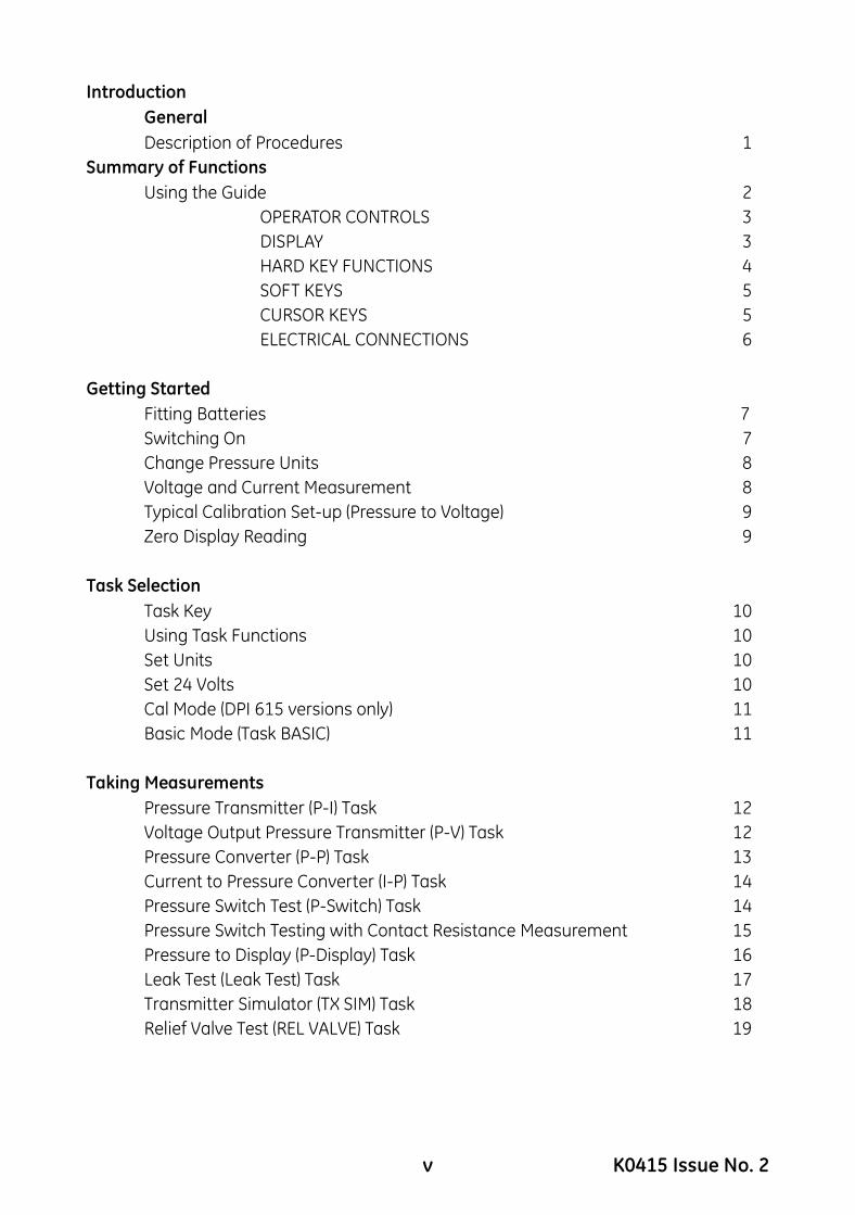
Using this guideThe following key symbols are used in the procedure diagrams that follow:SELECT VALUEShaded cursor keys indicate that a combination of these four keys, Up, Down, Left and Right should be used to (e.g.) enter an alpha numeric value or to select a function.
Indicates the ENTER key. Used to confirm an operation or a selection. Shading indicates key operation.
Exit key, used to clear current menu selection and return to next menu level above current level. Used as an escape key from current operation. Shading indicates key operation.
Hardkey (total 7). Legend beside key symbol indicates function. Shading indicates key operation.
Maximum Instrument RatingsThe following table shows the maximum measurement input ratings of the instrument that should not be exceeded.
Note 1: The display flashes if the input pressure, voltage or current overrange.
Note 2: Max applied voltage for external loop supply = 30V dc (see page 8).
PRESSURE 120% FULL SCALE
VOLTAGE 50 V d.c.
CURRENT 55 mA d.c.
K0415 Issue No. 2 2
INTRODUCTION Summary of Functions
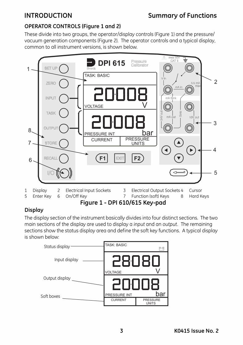
OPERATOR CONTROLS (Figure 1 and 2)These divide into two groups, the operator/display controls (Figure 1) and the pressure/vacuum generation components (Figure 2). The operator controls and a typical display, common to all instrument versions, is shown below.1 Display 2 Electrical Input Sockets 3 Electrical Output Sockets 4 Cursor5 Enter Key 6 On/Off Key 7 Function (soft) Keys 8 Hard Keys
Figure 1 - DPI 610/615 Key-padDisplayThe display section of the instrument basically divides into four distinct sections. The two main sections of the display are used to display a input and an output. The remaining sections show the status display area and define the soft key functions. A typical display is shown below:
PRESSURE INT bar
VOLTAGE V
F2F16
8
7
1
CURRENT PRESSUREUNITS
TASK: BASIC
DPI 615
2
3
4
5
PRESSURE INT bar
VOLTAGE V
CURRENTUNITS
PRESSURE
TASK: BASIC+-
Status display
Input display
Output display
Soft boxes
3 K0415 Issue No. 2

INTRODUCTION Summary of Functions
HARD KEY FUNCTIONS (Figure 1)* These key functions are not available in BASIC mode
Key FunctionPage
reference
I/O This key is used to turn the instrument ON and OFF. 7
SETUP*The SETUP key provides access to the instrument’s general configuration parameters that are set up to certain default parameters on delivery.
37
ZEROThe ZERO key can be used to zero either the selected input or output display, if the display reading is within 5% of zero. Attempts to zero a larger offset result in an error message, Zero too large.
9
INPUT* The INPUT key is used to select the input parameter to be displayed. 20, 21
TASK
The TASK key is used as a means of rapidly configuring the instrument for a number of different types of external device calibration. There are twenty task configurations available, eleven of which are pre-programmed and nine are user definable
10
OUTPUT* The OUTPUT key is used to select output parameter to be displayed. 25-28
STORE*Depending upon how the instrument’s STORE mode is setup, this key is used either to store up to 20 display screens (in SNAPSHOT mode), or to manually log a screen in DATALOG mode.
30-36
RECALL*
This key is used to recall a previously stored screen to the display. Depending on the STORE mode set-up, operation of this key recalls either the snapshot of a previously stored screen or datalog file. In STORE mode, selection displays the last screen stored. By using the cursor keys, the operator can scroll either forward or back through memory locations.
30, 32-36
ENTER The ENTER key is used either to enter data (accept entered data), or, in conjunction with the soft keys, to accept a given selection.
2
EXIT
The EXIT key operates in conjunction with all the other hard and soft keys to exit from the current screen or menu level, to the level immediately preceding it . To quit completely from any menu level, press EXIT until the MEASURE/SOURCE screen is displayed.
2
K0415 Issue No. 2 4
INTRODUCTION Summary of Functions
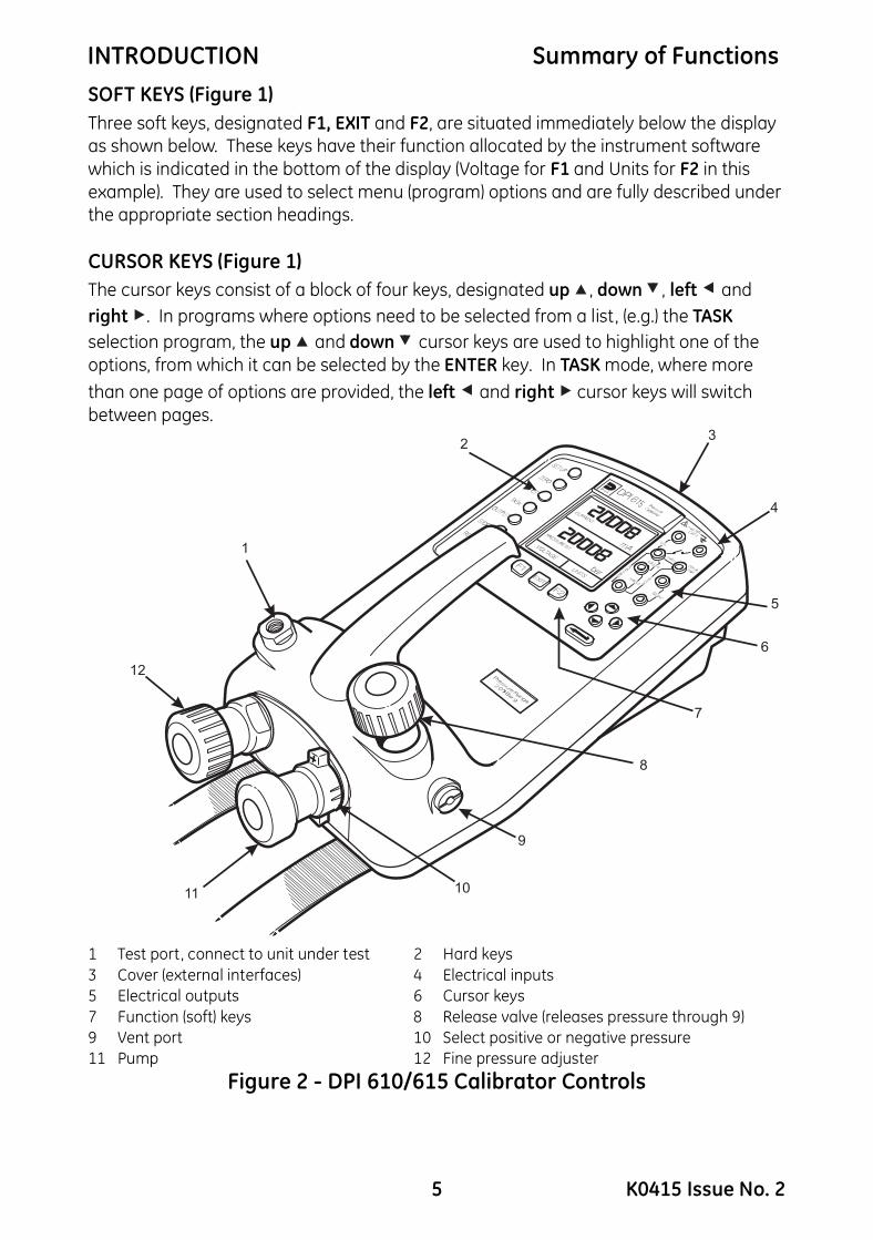
SOFT KEYS (Figure 1)Three soft keys, designated F1, EXIT and F2, are situated immediately below the display as shown below. These keys have their function allocated by the instrument software which is indicated in the bottom of the display (Voltage for F1 and Units for F2 in this example). They are used to select menu (program) options and are fully described under the appropriate section headings.CURSOR KEYS (Figure 1)The cursor keys consist of a block of four keys, designated up , down , left and right . In programs where options need to be selected from a list, (e.g.) the TASK selection program, the up and down cursor keys are used to highlight one of the options, from which it can be selected by the ENTER key. In TASK mode, where more than one page of options are provided, the left and right cursor keys will switch between pages.
1 Test port, connect to unit under test 2 Hard keys3 Cover (external interfaces) 4 Electrical inputs5 Electrical outputs 6 Cursor keys7 Function (soft) keys 8 Release valve (releases pressure through 9)9 Vent port 10 Select positive or negative pressure11 Pump 12 Fine pressure adjuster
Figure 2 - DPI 610/615 Calibrator Controls
7
8
9
5
6
4
3
11 10
12
1
2
5
5 K0415 Issue No. 2

INTRODUCTION Summary of Functions
ELECTRICAL CONNECTIONS 1 Cover, closed whennot using connectors2 External transducer3 RS232 connector4 Temperature sensor5 DC power input
Figure 3 - Electrical System ConnectionsMeasurement inputs and Source outputs are made via the control panel sockets as shown below.
1 Status display 2 Input display 3 Electrical input sockets4 Electrical output sockets 5 Output display
Figure 4 - Electrical Measurement Inputs/Outputs
1
2
3
4
5
PRESSURE INT bar
VOLTAGE V
F2F1
2
CURRENTUNITS
5
3
4
1
PRESSURE
TASK: BASIC
DPI 615
INPUTS
OUTPUTS
K0415 Issue No. 2 6
Getting Started
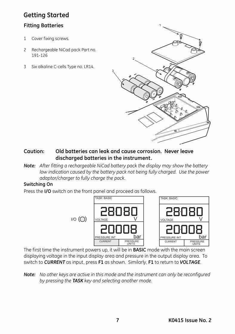
Fitting Batteries1 Cover fixing screws.
2 Rechargeable NiCad pack Part no. 191-126
3 Six alkaline C-cells Type no. LR14.
Caution: Old batteries can leak and cause corrosion. Never leave discharged batteries in the instrument.
Note: After fitting a rechargeable NiCad battery pack the display may show the battery low indication caused by the battery pack not being fully charged. Use the power adaptor/charger to fully charge the pack.
Switching OnPress the I/O switch on the front panel and proceed as follows.
The first time the instrument powers up, it will be in BASIC mode with the main screen displaying voltage in the input display area and pressure in the output display area. To switch to CURRENT as input, press F1 as shown. Similarly, F1 to return to VOLTAGE.
Note: No other keys are active in this mode and the instrument can only be reconfigured by pressing the TASK key and selecting another mode.
1
2
3
7 K0415 Issue No. 2

Getting Started
Change Pressure UnitsTo change the pressure units proceed as follows. If the four units displayed are not the units required, press TASK and select any task, other than BASIC, press SETUP and proceed as detailed on page 37. To return to BASIC mode, press TASK and select BASIC.In BASIC mode, the instrument is configured to carry out basic Pressure to Voltage (P to V) or Pressure to Current (P to I) tests, a typical test procedure follows.
Voltage and Current MeasurementConnect the electrical input sockets as follows for voltage and current measurements. Use the test leads provided and DO NOT push bare wires into the sockets.
Note: Maximum applied voltage = 50V dc,. Maximum input current = 55mA dc
Note: Maximum applied voltage for external loop supply = 30V dc
55mA
Vin
mA in
mA Sink
mA out 10V out
Xm
tr
24
Vo
ut
max 50VCAT II
max55mA
Vin
mA in
mA Sink
mA out 10V out
Xm
tr
24
Vo
ut
max 50VCAT II
max
+
-
V
55mA
Vin
mA in
mA Sink
mA out 10V out
Xm
tr
24
Vo
ut
max 50VCAT II
max
+
-
LOAD
K0415 Issue No. 2 8

Getting Started
Typical Calibration Set-up (Pressure to Voltage)Connect a device under test to the instrument as shown below:A - External pressure source (indicator instruments only) B - Pressure regulatorC - Excitation 10VGeneral procedure• Use the hand-pump to pressurize the system to the required level as indicated on the
display. Allow the display to settle and screw the volume adjuster in or out as a fine adjustment to the required pressure. Record the input (e.g.) Voltage, reading at each applied pressure.
Zero Display ReadingBoth the input and output readings can be set to zero using the ZERO key and if the displayed reading is within 5% of zero. To zero either the INPUT or OUTPUT displays, proceed as follows:
F2F1
P
V
-+
+
-
+
-
bar
V
CURRENTPRESSURE
UNITS
TASK: BASIC
DPI 615
A
B
C
ZERO
VOLTAGE
PRESSURE INT bar
V
YESZERO VOLTAGE DC ?
NO
VOLTAGE
PRESSURE INT bar
V
ZEROINPUT
ZEROOUTPUT
TASK: BASIC TASK: BASIC
ZERO
VOLTAGE
PRESSURE INT bar
V
YESZERO INTERNAL SENSOR ?
NO
VOLTAGE
PRESSURE INT bar
V
ZEROINPUT
ZEROOUTPUT
TASK: BASIC TASK: BASIC
9 K0415 Issue No. 2
Task Selection
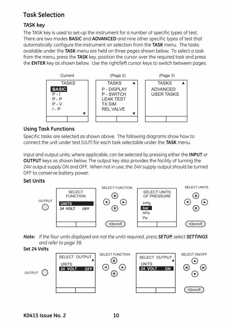
TASK keyThe TASK key is used to set-up the instrument for a number of specific types of test. There are two modes BASIC and ADVANCED and nine other specific types of test that automatically configure the instrument on selection from the TASK menu. The tasks available under the TASK menu are held on three pages shown below. To select a task from the menu, press the TASK key, position the cursor over the required task and press the ENTER key as shown below. Use the right/left cursor keys to switch between pages.Using Task FunctionsSpecific tasks are selected as shown above. The following diagrams show how to connect the unit under test (UUT) for each task selectable under the TASK menu.
Input and output units, where applicable, can be selected by pressing either the INPUT or OUTPUT keys as shown below. The output key also provides the facility of turning the 24V output supply ON and OFF. When not in use, the 24V supply output should be turned OFF to conserve battery power.
Set Units
Note: If the four units displayed are not the units required, press SETUP, select SETTINGS and refer to page 38.
Set 24 Volts
BASICUSER TASKSP - SWITCHADVANCED
REL VALVE
LEAK TESTTX SIM
TASKS TASKS TASKS
P - DISPLAYP - I
I - P
P - PP - V
Current (Page 2) (Page 3)
OUTPUT
SELECTFUNCTION
UNITS
ONinHg
hPa
Pa
bar
SELECT FUNCTION
SELECT UNITSOF PRESSURE
SELECT UNITS
24 VOLT OFF
OUTPUT
SELECT ON/OFFSELECT FUNCTIONSELECT OUTPUT
24 VOLT OFF
UNITS24 VOLT ON
UNITS
SELECT OUTPUT
ON
K0415 Issue No. 2 10
Task Selection
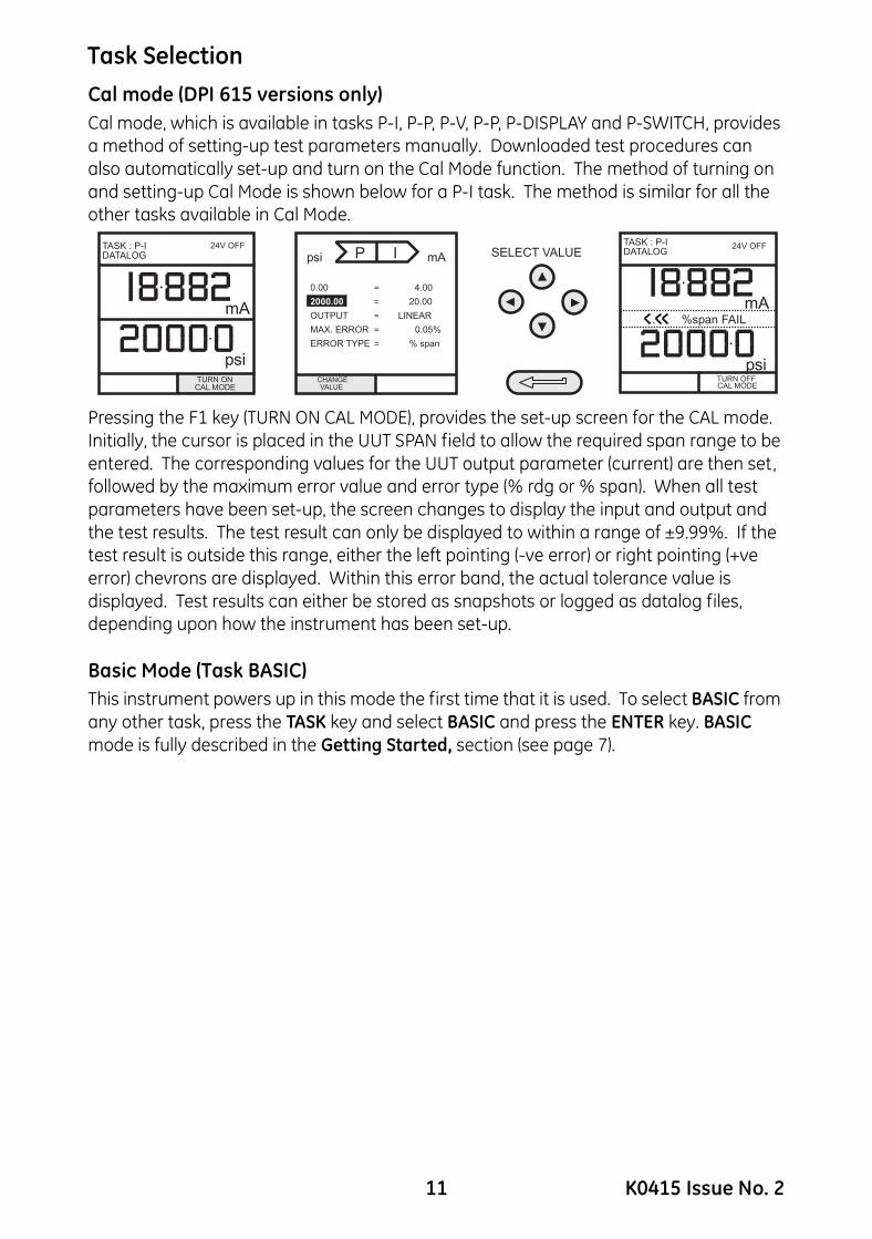
Cal mode (DPI 615 versions only)Cal mode, which is available in tasks P-I, P-P, P-V, P-P, P-DISPLAY and P-SWITCH, provides a method of setting-up test parameters manually. Downloaded test procedures can also automatically set-up and turn on the Cal Mode function. The method of turning on and setting-up Cal Mode is shown below for a P-I task. The method is similar for all the other tasks available in Cal Mode.Pressing the F1 key (TURN ON CAL MODE), provides the set-up screen for the CAL mode. Initially, the cursor is placed in the UUT SPAN field to allow the required span range to be entered. The corresponding values for the UUT output parameter (current) are then set, followed by the maximum error value and error type (% rdg or % span). When all test parameters have been set-up, the screen changes to display the input and output and the test results. The test result can only be displayed to within a range of ±9.99%. If the test result is outside this range, either the left pointing (-ve error) or right pointing (+ve error) chevrons are displayed. Within this error band, the actual tolerance value is displayed. Test results can either be stored as snapshots or logged as datalog files, depending upon how the instrument has been set-up.
Basic Mode (Task BASIC)This instrument powers up in this mode the first time that it is used. To select BASIC from any other task, press the TASK key and select BASIC and press the ENTER key. BASIC mode is fully described in the Getting Started, section (see page 7).
0.00
2000.00
OUTPUT
MAX. ERROR
ERROR TYPE
CHANGEVALUE
psi
=
=
=
=
=
mA
4.00
20.00
LINEAR
0.05%
% span
P I SELECT VALUE
psi
mA
TASK : P-IDATALOG
24V OFF
..........
. %span FAIL
TURN OFFCAL MODE
TURN ONCAL MODE
mA
TASK : P-IDATALOG
24V OFF
..........
psi
11 K0415 Issue No. 2
Taking Measurements
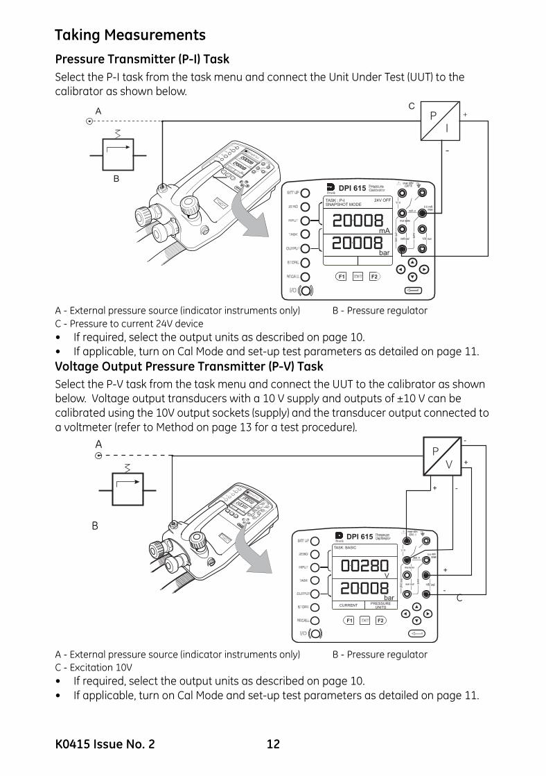
Pressure Transmitter (P-I) TaskSelect the P-I task from the task menu and connect the Unit Under Test (UUT) to the calibrator as shown below.A - External pressure source (indicator instruments only) B - Pressure regulator C - Pressure to current 24V device • If required, select the output units as described on page 10.• If applicable, turn on Cal Mode and set-up test parameters as detailed on page 11.Voltage Output Pressure Transmitter (P-V) TaskSelect the P-V task from the task menu and connect the UUT to the calibrator as shown below. Voltage output transducers with a 10 V supply and outputs of ±10 V can be calibrated using the 10V output sockets (supply) and the transducer output connected to a voltmeter (refer to Method on page 13 for a test procedure).
A - External pressure source (indicator instruments only) B - Pressure regulatorC - Excitation 10V• If required, select the output units as described on page 10.• If applicable, turn on Cal Mode and set-up test parameters as detailed on page 11.
P
I
+
-
F2F1
bar
mA
TASK : P-ISNAPSHOT MODE
24V OFF
DPI 615
A
B
C
F2F1
P
V
-+
+
-
+
-
bar
V
CURRENTPRESSURE
UNITS
TASK: BASIC
DPI 615
A
B
C
K0415 Issue No. 2 12
Taking Measurements
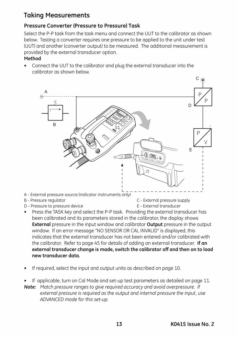
Pressure Converter (Pressure to Pressure) TaskSelect the P-P task from the task menu and connect the UUT to the calibrator as shown below. Testing a converter requires one pressure to be applied to the unit under test (UUT) and another (converter output) to be measured. The additional measurement is provided by the external transducer option. Method• Connect the UUT to the calibrator and plug the external transducer into thecalibrator as shown below.
A - External pressure source (indicator instruments only)B - Pressure regulator C - External pressure supplyD - Pressure to pressure device E - External transducer• Press the TASK key and select the P-P task. Providing the external transducer has
been calibrated and its parameters stored in the calibrator, the display shows External pressure in the input window and calibrator Output pressure in the output window. If an error message “NO SENSOR OR CAL INVALID” is displayed, this indicates that the external transducer has not been entered and/or calibrated with the calibrator. Refer to page 45 for details of adding an external transducer. If an external transducer change is made, switch the calibrator off and then on to load new transducer data.
• If required, select the input and output units as described on page 10.
• If applicable, turn on Cal Mode and set-up test parameters as detailed on page 11.Note: Match pressure ranges to give required accuracy and avoid overpressure. If
external pressure is required as the output and internal pressure the input, use ADVANCED mode for this set-up.
A
B
C
D
E
13 K0415 Issue No. 2
Taking Measurements
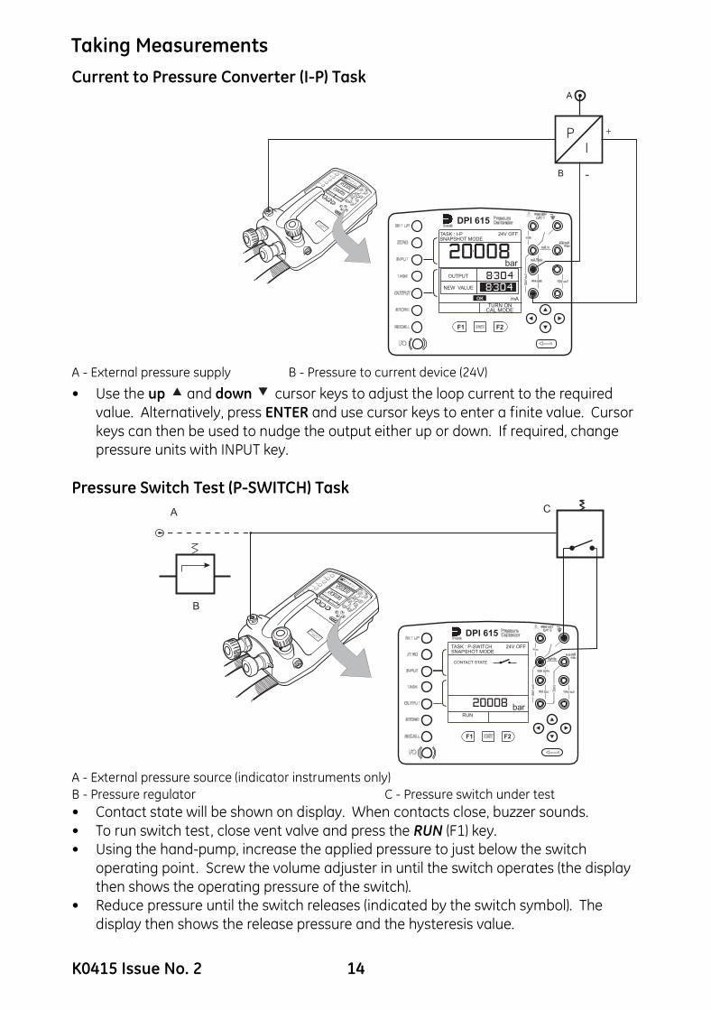
Current to Pressure Converter (I-P) TaskA - External pressure supply B - Pressure to current device (24V)
• Use the up and down cursor keys to adjust the loop current to the required value. Alternatively, press ENTER and use cursor keys to enter a finite value. Cursor keys can then be used to nudge the output either up or down. If required, change pressure units with INPUT key.
Pressure Switch Test (P-SWITCH) Task
A - External pressure source (indicator instruments only)B - Pressure regulator C - Pressure switch under test • Contact state will be shown on display. When contacts close, buzzer sounds.• To run switch test, close vent valve and press the RUN (F1) key. • Using the hand-pump, increase the applied pressure to just below the switch
operating point. Screw the volume adjuster in until the switch operates (the display then shows the operating pressure of the switch).
• Reduce pressure until the switch releases (indicated by the switch symbol). The display then shows the release pressure and the hysteresis value.
P
I
+
-
F2F1
bar
OUTPUT
NEW VALUE
mAOK
TASK : I-PSNAPSHOT MODE
24V OFF
DPI 615
TURN ONCAL MODE
A
B
F2F1
barRUN
CONTACT STATE
TASK : P-SWITCHSNAPSHOT MODE
24V OFF
DPI 615
A
B
C
K0415 Issue No. 2 14

Taking Measurements
Pressure Switch Testing with Contact Resistance MeasurementA - External pressure source (indicator instruments only)B - Pressure regulatorC - Pressure switch under test To perform switch test with contact resistance measurement, select P-SWITCH and proceed as follows:
To ensure accurate measurements it is recommended that the zero procedure (that compensates for the resistance of the test leads) is carried out before performing this test.Note: Allow sufficient time after contact closure for the resistance to stabilize.
The switch test is performed in the same way as the previous section, except that the contact resistance is measured and displayed with the results.
F2F1
barRUN
CONTACT STATE
TASK : P-SWITCHSNAPSHOT MODE
24V OFF
DPI 615
A
B
C
INPUT
SELECT
RESISTANCE
SELECT
ZEROSELECT
FUNCTION
RESIST OFF
ZERO
SELECT
FUNCTION
RESIST ON
ZERO
Connect Vin +, SW + andmA in + together.Connect Vin +, SW + andmA in + together.
Connect switch test leadsacross switch symbol.Connect switch test leadsacross switch symbol.
Open circuit test leadsOpen circuit test leads
Press ENTER to continue.Press ENTER to continue.
Switch Resistance inputnow ready for use.Switch Resistance inputnow ready for use.
Press ENTER to continue.Press ENTER to continue.
Open circuit test leads.Open circuit test leads.
Now short test leads.Now short test leads.
Press ENTER to continue.Press ENTER to continue.
barRUN
CONTACT STATE
TASK : P-SWITCHSNAPSHOT MODE
24V OFF
24V OFF
RUN
bar
CONTACT STATE
CLOSED AT 15.060 barOPENED AT 14.059 barHYSTERESIS 1.001 barRESISTANCE 3 m�
TASK: P-SWITCHSNAPSHOT MODE
15 K0415 Issue No. 2
Taking Measurements
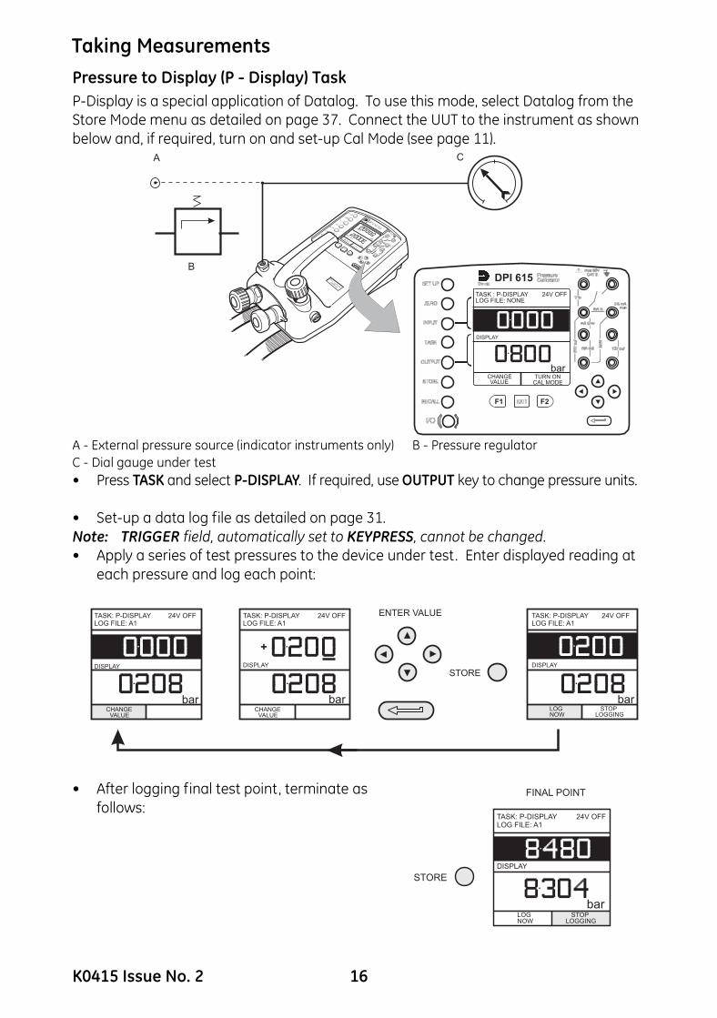
Pressure to Display (P - Display) TaskP-Display is a special application of Datalog. To use this mode, select Datalog from the Store Mode menu as detailed on page 37. Connect the UUT to the instrument as shown below and, if required, turn on and set-up Cal Mode (see page 11).A - External pressure source (indicator instruments only) B - Pressure regulatorC - Dial gauge under test • Press TASK and select P-DISPLAY. If required, use OUTPUT key to change pressure units.
• Set-up a data log file as detailed on page 31.Note: TRIGGER field, automatically set to KEYPRESS, cannot be changed.• Apply a series of test pressures to the device under test. Enter displayed reading at
each pressure and log each point:
• After logging final test point, terminate as follows:
F2F1
bar
DISPLAY
CHANGEVALUE
TASK : P-DISPLAYLOG FILE: NONE
24V OFF
TURN ONCAL MODE
DPI 615
A
B
C
ENTER VALUE
DISPLAY
CHANGEVALUE
DISPLAY
CHANGEVALUE
DISPLAY
LOGNOW
STOPLOGGING
STORE
+
bar barbar
TASK: P-DISPLAYLOG FILE: A1
TASK: P-DISPLAYLOG FILE: A1
TASK: P-DISPLAYLOG FILE: A1
24V OFF 24V OFF 24V OFF
DISPLAY
barLOGNOW
STOPLOGGING
STORE
FINAL POINT
TASK: P-DISPLAYLOG FILE: A1
24V OFF
K0415 Issue No. 2 16

Taking Measurements
Leak Test (LEAK TEST) TaskA - External pressure source (indicator instruments only) B - Pressure regulatorC - Unit/system under test • If required, use the INPUT key to change pressure units.
• Set-up the leak test WAIT and DURATION times to the required values as shown below. Recommended minimum wait period - 3 minutes.
• Close the vent valve and pressurize the unit/system to the required LEAK TEST pressure.
• Press the RUN (F2) key to start the leak test. When completed, the beeper sounds and the leak test results are written to the display.
A
B
C
PRESSURE INT bar
F2F1
RUNCHANGEVALUE
WAIT
DURATION
START PRESS
STOP PRESS
PRESS CHANGELEAK RATE
secs
secs
bar
bar
barbar/m
60
60
TASK : LEAK TESTSNAPSHOT MODE
24 V OFF
DPI 615
SET WAIT TIME SET DURATION
CIONWAIT
DURATION
START PRESS
STOP PRESS
PRESS CHANGE
180
LEAK RATE
secs
secs
bar
bar
bar
bar/m
60
PRESSURE INT bar
CHANGEVALUE
RUN
TASK : LEAK TESTSNAPSHOT MODE
CIONWAIT
DURATION
START PRESS
STOP PRESS
PRESS CHANGE
180
LEAK RATE
secs
secs
bar
bar
bar
bar/m
60
PRESSURE INT bar
CHANGEVALUE
RUN
TASK : LEAK TESTSNAPSHOT MODE
24 V OFF24 V OFF
17 K0415 Issue No. 2
Taking Measurements
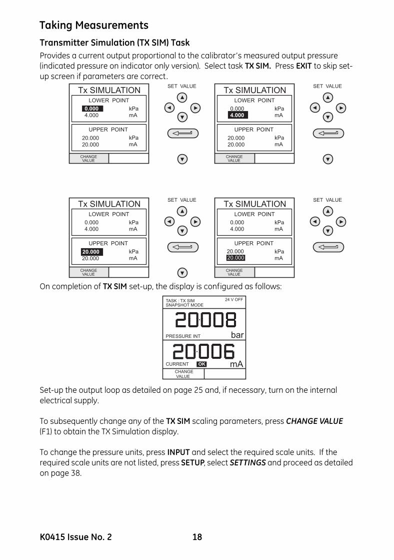
Transmitter Simulation (TX SIM) TaskProvides a current output proportional to the calibrator’s measured output pressure (indicated pressure on indicator only version). Select task TX SIM. Press EXIT to skip set-up screen if parameters are correct.On completion of TX SIM set-up, the display is configured as follows:
Set-up the output loop as detailed on page 25 and, if necessary, turn on the internal electrical supply.
To subsequently change any of the TX SIM scaling parameters, press CHANGE VALUE (F1) to obtain the TX Simulation display.
To change the pressure units, press INPUT and select the required scale units. If the required scale units are not listed, press SETUP, select SETTINGS and proceed as detailed on page 38.
PRESSURE INT bar
mACURRENT OK
TASK : TX SIMSNAPSHOT MODE
CHANGEVALUE
24 V OFF
K0415 Issue No. 2 18

Taking Measurements
Relief Valve Test (REL VALVE) TaskTo carry out a relief valve test, press TASK and select REL VALVE. Connect the output pressure port of the instrument to an external system as shown below:A - External pressure source (indicator instruments only) B - Pressure regulatorC - Relief valve under test • To change the pressure units, if required, press INPUT and select the required
units using the cursor keys.
• If necessary, turn on the 24 Volt internal supply by pressing OUTPUT, select 24 VOLT and switch ON with the right cursor button and press ENTER.
• Close the vent valve and, using the hand-pump or external pressure supply, apply pressure to the relief valve under test.
• When the relief valve operates, the maximum recorded pressure indicates the operating point of the valve.
Note: The STORE key can be used for this purpose. Use right cursor key initially, followed by up/down keys to enter Snapshot text).
• Record the test results.
• Open vent valve to release test pressure.
Note: If using external pressure supply, isolate supply before opening the vent valve.
F2F1
bar
bar
RESET
MAXIMUM
MINIMUM
MAX/MIN
TASK : RELVALVESNAPSHOT MODE
24V OFF
DPI 615
A
B
C
19 K0415 Issue No. 2

Advanced Task Select Input
GeneralAdvanced task allows the user to configure the instrument to monitor one of a number of different input measurements and outputs (sources). Additionally, five process functions, Tare, Max/Min, Filter, Flow and % Span can be applied to the input functions.Select InputTo display an input channel, select ADVANCED task from the task menu. The display shows the list of the input selections and, if available, the PROCESS soft box (F1) and the UNITS soft box (F2). The following procedure shows the method of input channel selection and the method of changing units:
Note: Left/right arrow keys function as page up/down keys.
Refer to pages 21 to 24 for details of process functions.Ambient Temperature MeasurementTo set-up the instrument to read ambient temperature, proceed as follows:
Note: Make sure the temperature reading has stabilized.
SELECT UNITSSELECT UNITSOF PRESSURE
INPUT
SELECT INPUT
SELECT INPUT
PRESSURE INT
VOLTAGE
CURRENT
PRESSURE EXT
AMBIENT TEMP
PROCESS UNITS
INPUT
SELECT INPUT
SELECT INPUT
NO INPUT
inHg
bar
hPa
Pa
SELECT UNITSSELECT AIRTEMPERATURE
INPUT
SELECT INPUT
SELECT INPUT
PROCESS UNITS
UNITS
CELSIUS
FAHRENHEIT
AMBIENT TEMP
NO INPUT
K0415 Issue No. 2 20
Advanced Task Process Functions
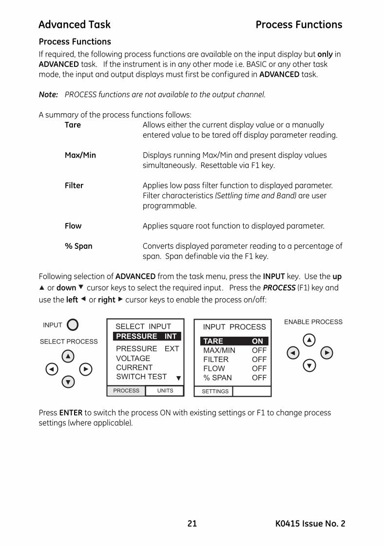
Process FunctionsIf required, the following process functions are available on the input display but only in ADVANCED task. If the instrument is in any other mode i.e. BASIC or any other task mode, the input and output displays must first be configured in ADVANCED task.Note: PROCESS functions are not available to the output channel.
A summary of the process functions follows:Tare Allows either the current display value or a manually
entered value to be tared off display parameter reading.
Max/Min Displays running Max/Min and present display values simultaneously. Resettable via F1 key.
Filter Applies low pass filter function to displayed parameter. Filter characteristics (Settling time and Band) are user programmable.
Flow Applies square root function to displayed parameter.
% Span Converts displayed parameter reading to a percentage of span. Span definable via the F1 key.
Following selection of ADVANCED from the task menu, press the INPUT key. Use the up
or down cursor keys to select the required input. Press the PROCESS (F1) key and use the left or right cursor keys to enable the process on/off:
Press ENTER to switch the process ON with existing settings or F1 to change process settings (where applicable).
21 K0415 Issue No. 2

Advanced Task Process Functions
Tare Process FunctionTo set-up a Tare function, enable TARE from the process menu and press F1 to enter the Tare SETTINGS functions.Disable TARE by entering process menu and turning the function OFF.
Note: Last TARE setting is retained and will be applied when function is next enabled.
Tare Current Input Reading To tare off the current display reading, proceed as follows:
Tare Off An Entered Value To tare off an entered value, proceed as follows:
Note: Display shows the last entered Tare value.
VOLTAGE V
T
PRESSURE INT bar
VOLTAGE V
MAKE READINGZERO
TARE OFFA VALUE
PRESSURE INT bar
TASK : ADVANCEDSNAPSHOT MODE
24V OFF 24V OFFTASK : ADVANCEDSNAPSHOT MODE
VOLTAGE V
MAKE READINGZERO
TARE OFFA VALUE
PRESSURE INT bar
TASK : ADVANCEDSNAPSHOT MODE
ENTER VALUE
VOLTAGE V
PRESSURE INT bar
TASK : ADVANCEDSNAPSHOT MODE
VALUE: 10.000NEW VALUE: _
24V OFF 24V OFF
K0415 Issue No. 2 22
Advanced Task Process Functions
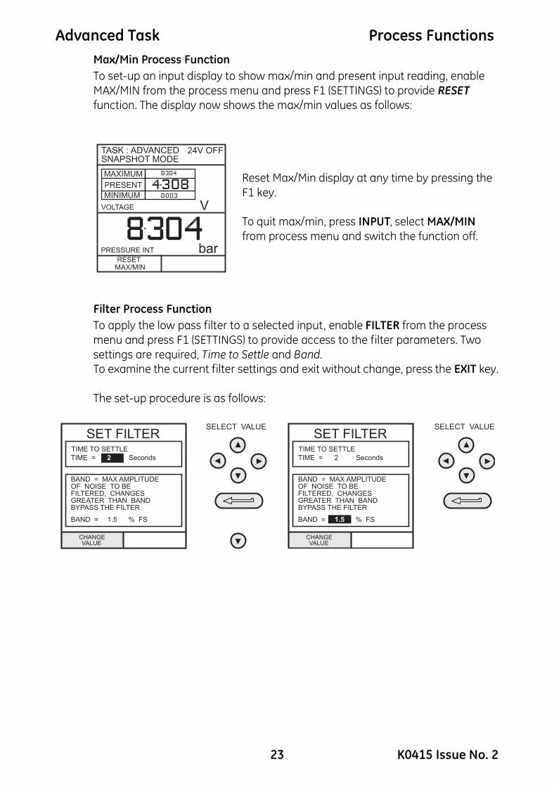
Max/Min Process FunctionTo set-up an input display to show max/min and present input reading, enable MAX/MIN from the process menu and press F1 (SETTINGS) to provide RESET function. The display now shows the max/min values as follows:Reset Max/Min display at any time by pressing the F1 key.
To quit max/min, press INPUT, select MAX/MIN from process menu and switch the function off.
Filter Process FunctionTo apply the low pass filter to a selected input, enable FILTER from the process menu and press F1 (SETTINGS) to provide access to the filter parameters. Two settings are required, Time to Settle and Band.To examine the current filter settings and exit without change, press the EXIT key.
The set-up procedure is as follows:
TASK : ADVANCEDSNAPSHOT MODE
24V OFF
23 K0415 Issue No. 2
Advanced Task Process Functions
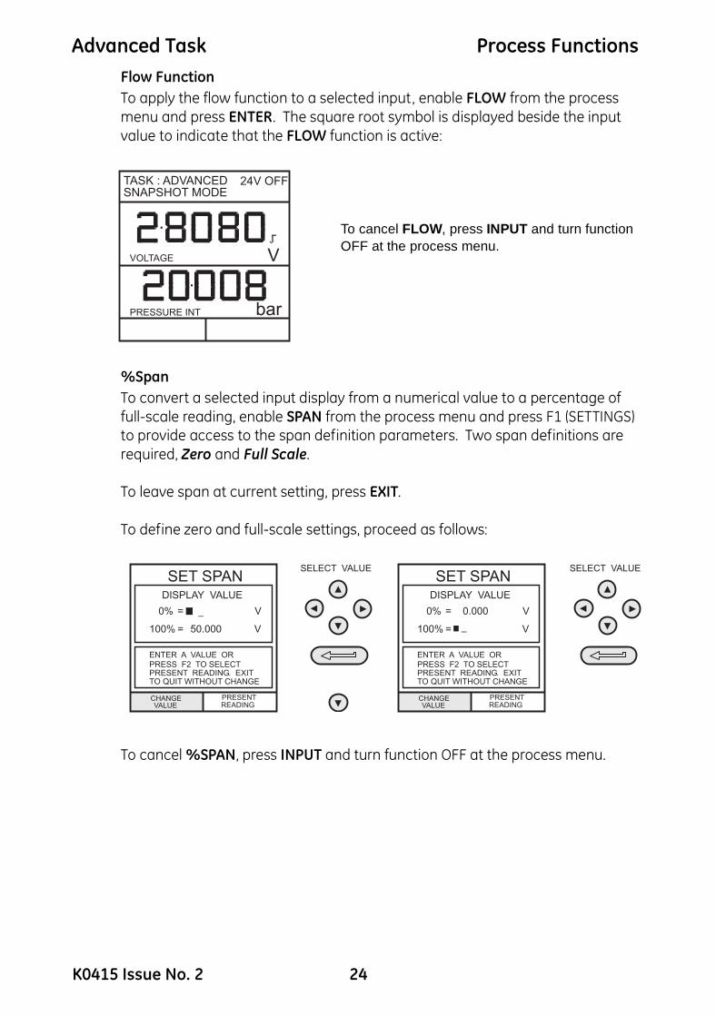
Flow FunctionTo apply the flow function to a selected input, enable FLOW from the process menu and press ENTER. The square root symbol is displayed beside the input value to indicate that the FLOW function is active:To cancel FLOW, press INPUT and turn function OFF at the process menu.
%SpanTo convert a selected input display from a numerical value to a percentage of full-scale reading, enable SPAN from the process menu and press F1 (SETTINGS) to provide access to the span definition parameters. Two span definitions are required, Zero and Full Scale.
To leave span at current setting, press EXIT.
To define zero and full-scale settings, proceed as follows:
To cancel %SPAN, press INPUT and turn function OFF at the process menu.
PRESSURE INT bar
VOLTAGE V
TASK : ADVANCEDSNAPSHOT MODE
24V OFF
K0415 Issue No. 2 24

Advanced Task Select Output
Select OutputTo display an output channel, select ADVANCED mode from the task menu. The display shows the list of output selections and, if available, the UNITS soft box (F2).The following procedure shows the method of output channel selection from two pages of options. The second page can be obtained directly from the first by pressing the right
cursor key:
Note: Left and right keys function as page up/down keys.
To change the output units (pressure channels only), select the channel with the cursor keys and press F2 before pressing ENTER.
Electrical Outputs (Loop Power)For all the electrical outputs, the output loop can be powered either by the instrument’s internal 24V supply (sourcing) or alternatively, from an external supply (current sinking).To conserve battery power, the 24V internal supply should be switched off (even when not being used to power an external loop).
External connections to the front panel of the instrument are shown below for both sourcing and sinking applications:
OUTPUT
SELECT OUTPUTSELECT OUTPUT
UNITS
PRESSURE INT
SELECT OUTPUT
NO OUTPUT
24 VOLT OFF
PRESSURE EXT
mA STEP
mA RAMP
mA VALUE
55mA
Vin
mA in
mA Sink
mA out 10V out
Xm
tr
24
Vo
ut
max 50VCAT II
max55mA
Vin
mA in
mA Sink
mA out 10V out
Xm
tr
24
Vo
ut
max 50VCAT II
-
+
max
CURRENT SOURCING(24V ON)
CURRENT SINKING(24V OFF)
Ext. d.c. Supply(30V Max)
LOAD
LOAD
25 K0415 Issue No. 2
Advanced Task Select Output
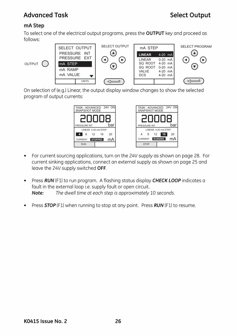
mA StepTo select one of the electrical output programs, press the OUTPUT key and proceed as follows:On selection of (e.g.) Linear, the output display window changes to show the selected program of output currents:
• For current sourcing applications, turn on the 24V supply as shown on page 28. For current sinking applications, connect an external supply as shown on page 25 and leave the 24V supply switched OFF.
• Press RUN (F1) to run program. A flashing status display CHECK LOOP indicates a fault in the external loop i.e. supply fault or open circuit.Note: The dwell time at each step is approximately 10 seconds.
• Press STOP (F1) when running to stop at any point. Press RUN (F1) to resume.
PRESSURE INT barLINEAR 4-20 mA STEP
4 8 12 16 20
RUN
PRESSURE INT barLINEAR 4-20 mA STEP
4 8 12 16 20
STOP
CURRENT mASTOPPED CURRENT mARUNNING
TASK : ADVANCEDSNAPSHOT MODE
24V ON 24V ONTASK : ADVANCEDSNAPSHOT MODE
K0415 Issue No. 2 26
Advanced Task Select Output
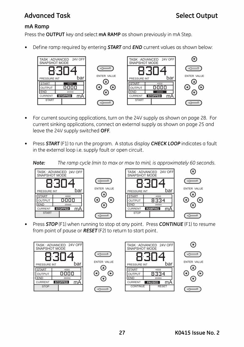
mA RampPress the OUTPUT key and select mA RAMP as shown previously in mA Step.• Define ramp required by entering START and END current values as shown below:
• For current sourcing applications, turn on the 24V supply as shown on page 28. For current sinking applications, connect an external supply as shown on page 25 and leave the 24V supply switched OFF.
• Press START (F1) to run the program. A status display CHECK LOOP indicates a fault
in the external loop i.e. supply fault or open circuit .
Note: The ramp cycle (min to max or max to min), is approximately 60 seconds.
• Press STOP (F1) when running to stop at any point. Press CONTINUE (F1) to resume from point of pause or RESET (F2) to return to start point.
ENTER VALUEENTER VALUEPRESSURE INT bar
START
START
OUTPUT
END
CURRENT mASTOPPED
TASK : ADVANCEDSNAPSHOT MODE
PRESSURE INT bar
START
START
OUTPUT
END
CURRENT mASTOPPED
TASK : ADVANCEDSNAPSHOT MODE
24V OFF 24V OFF
ENTER VALUEENTER VALUEPRESSURE INT bar
START
START
OUTPUT
END
CURRENT mASTOPPED
TASK : ADVANCEDSNAPSHOT MODE
PRESSURE INT bar
STOP
START
OUTPUT
END
CURRENT mA
TASK : ADVANCEDSNAPSHOT MODE
RAMPING
24V OFF 24V OFF
ENTER VALUEENTER VALUEPRESSURE INT bar
STOP
START
OUTPUT
END
CURRENT mASTOPPED
TASK : ADVANCEDSNAPSHOT MODE
PRESSURE INT bar
CONTINUE RESET
START
OUTPUT
END
CURRENT mA
TASK : ADVANCEDSNAPSHOT MODE
PAUSED
24V OFF 24V OFF
27 K0415 Issue No. 2
Advanced Task Select Output
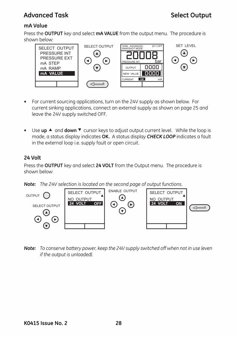
mA ValuePress the OUTPUT key and select mA VALUE from the output menu. The procedure is shown below:• For current sourcing applications, turn on the 24V supply as shown below. For current sinking applications, connect an external supply as shown on page 25 and leave the 24V supply switched OFF.
• Use up and down cursor keys to adjust output current level. While the loop is made, a status display indicates OK. A status display CHECK LOOP indicates a fault in the external loop i.e. supply fault or open circuit .
24 VoltPress the OUTPUT key and select 24 VOLT from the Output menu. The procedure is shown below:
Note: The 24V selection is located on the second page of output functions.
Note: To conserve battery power, keep the 24V supply switched off when not in use (even if the output is unloaded).
SELECT OUTPUT SET LEVELSELECT OUTPUT
PRESSURE INTPRESSURE EXT
mA STEP
mA RAMP
mA VALUE
PRESSURE INT bar
OUTPUT
NEW VALUE
CURRENT mAOK
TASK : ADVANCEDSNAPSHOT MODE
24 V OFF
OUTPUT
ENABLE OUTPUT
SELECT OUTPUT
SELECT OUTPUT
24 VOLT OFFNO OUTPUT
SELECT OUTPUT
24 VOLT ONNO OUTPUT
K0415 Issue No. 2 28

Advanced Task Task Set-up/Removal
Define New TaskTo define a new task, proceed as follows.• Select ADVANCED from TASKS menu.
• Using the INPUT key, select the required input for the input display and set-up any process functions required.
• Using the OUTPUT key, select the required output for the output display.
• Press TASK and select free. Enter new task name as follows:
On completion of this procedure, the display reverts to newly set-up task as shown:
Clear TaskTo clear a user defined task, select TASK and proceed as follows:
29 K0415 Issue No. 2

Memory Operations Store
Saving Display or Data LogIn Store Mode three memory operations can be set-up: None, Snapshot and Data Log. Refer to Using Setup for details.Store Operations (Screen Snapshots)To store any display (menu displays excepted), press the STORE key. This saves the current display to the next available location. Supporting text (10 characters) may be appended. Twenty memory locations are available on a cyclic buffer. When all 20 have been used, store operations overwrite existing locations, starting at Location 1.
Recalling Stored Data (Screen Snapshots)
To recall a previously stored display, press the RECALL key. This recalls the last display saved. Press the left or right cursor keys to recall the previous or next locations respectively. To exit RECALL, press the EXIT key:
ENTER TEXT
STOREV
bar
TASK: ADVANCEDSNAPSHOT MODE
VOLTAGE V
bar
TASK: ADVANCEDSNAPSHOT MODE
SNAPSHOT 19
TEXT :
24V OFF 24V OFF
SELECT LOCATION
EXIT
RECALLVOLTAGE V
PRESSURE INT bar
TASK: ADVANCEDSNAPSHOT 2 TEST19
24 V OFF
K0415 Issue No. 2 30

Memory Operations Data Log
Data Log OperationsData Log is a special application of store mode that enables the calibrator to either automatically log displays at preset time intervals or to manually log a display on operation of the STORE key. Logged data is written to a user specified file.To set-up a Data Log file, proceed as follows:
• Select a task, other than BASIC. If using ADVANCED, set-up required output parameters.
• Use SETUP to select Data Log from the Store Mode Menu (see page 37).Auto Log (Timer)Press STORE and set up the Data Log file parameters as shown below. Use CHANGE VALUE (F1) followed by cursor keys to set field values. For Auto Log, set TRIGGER field to PERIODIC.
Manual LoggingEnter the file details as shown above and select KEYPRESS for TRIGGER field. Screen reverts to displayed parameters showing set-up file as shown below:
Use a combination of STORE and LOG NOW (F1) to log events as follows:
ENTER VALUE
STORE
LOGFILE2
PRESSURE INT bar
VOLTAGE V
CHANGEVALUE
DATA LOGGING
FILENAME :
DATE :
TIME :
TRIGGER:
PERIOD :
POINTS :
21/02/99
12:29
00:05
10
PERIODIC
CHANGEVALUE
DATA LOGGING
FILENAME :
DATE :
TIME :
TRIGGER :
PERIOD :
POINTS :
21/02/99
12:29
00:05
10
PERIODIC
STARTSTARTLOGGING LOGGING
(ANY KEY)
CLEAR
TASK : CO2INLETPOINT 10 OF 10
24 V OFF
CHANGEVALUE
DATA LOGGING
FILENAME :
DATE :
TIME :
TRIGGER :
PERIOD :
POINTS :
21/02/99
12:29
KEYPRESS
LOGFILE3
CHANGEVALUE
DATA LOGGING
FILENAME :
DATE :
TIME :
TRIGGER :
PERIOD :
POINTS :
21/02/99
12:29
KEYPRESS
LOGFILE3
PRESSURE INT bar
VOLTAGE V
LOG FILE : LOGFILE3TASK: ADVANCED
STARTLOGGING
STARTLOGGING
24 V OFF
PRESSURE INT bar
ENTER VALUE
PRESSURE INT bar
VOLTAGE V
LOG FILE : LOGFILE3LOG FILE : LOGFILE3TASK: ADVANCEDTASK: ADVANCED
STOREVOLTAGE V
LOGNOW
STOPLOGGING
24 V OFF24 V OFF
31 K0415 Issue No. 2

Memory Operations Data Log
Recall Data Log FilesTo recall a Data Log file to the display, ensure that DATA LOG is selected from the SETUP menu and proceed as follows:Data Log files can be displayed either as text (stored screens) or in graphical form. To display as text, proceed as follows from the File Summary menu. Select Auto Step to automatically review each screen at 1 second intervals or use the left or right cursor keys to manually review.
To display logged data in graphical form, on screen, proceed as follows from the File Summary menu:
FILE SUMMARY
REVIEW TRANSMIT
FILE NAME: TEST5
DATE:
TIME:
TRIGGER:
FILE SIZE:
06/11/99
15:58
KEYPRESS
886 bytes
FILELOGGED DATA
bar
mA
TASK : P-IDATALOG
AUTOSTEP
..........
. %span FAIL
DATA POINT1 OF 11
MANUAL REVIEW24 V OFF
K0415 Issue No. 2 32
Memory Operations Data Log
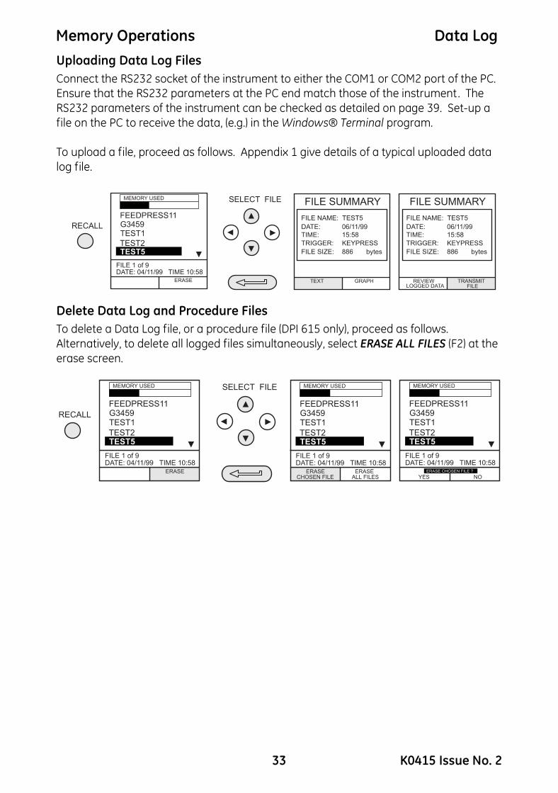
Uploading Data Log FilesConnect the RS232 socket of the instrument to either the COM1 or COM2 port of the PC. Ensure that the RS232 parameters at the PC end match those of the instrument. The RS232 parameters of the instrument can be checked as detailed on page 39. Set-up a file on the PC to receive the data, (e.g.) in the Windows® Terminal program.To upload a file, proceed as follows. Appendix 1 give details of a typical uploaded data log file.
Delete Data Log and Procedure FilesTo delete a Data Log file, or a procedure file (DPI 615 only), proceed as follows. Alternatively, to delete all logged files simultaneously, select ERASE ALL FILES (F2) at the erase screen.
33 K0415 Issue No. 2

Memory Operations Data Log
Downloading Procedure Files (DPI 615 instruments only)Complete test procedures may be downloaded from a PC to the DPI 615 instrument via the RS232 port. A procedure consists of a number of Druck Universal Command Interface (DUCI) commands that are usually assembled by a linking management software application (e.g.) Druck Intecal.Before downloading a procedure, the instrument must be in the REMOTE mode. To place the instrument into REMOTE mode, proceed as follows:
• Connect the instrument’s RS232 port to a free COM port on a PC.
• Ensure that the COMMS parameters of the PC match those of the instrument (refer to page 39).
• Ensure that the instrument is not already running a procedure. If it is, quit the
procedure.
• Download the procedure. Procedures are stored in the Data Log directory.
The following sequence shows a typical download sequence that starts with the instrument in LOCAL mode.
After the procedure file has been downloaded, the instrument is usually returned to the LOCAL mode by the last command in the procedure file. If the instrument remains in REMOTE mode, switch it OFF and ON to reset it .
K0415 Issue No. 2 34
Memory Operations Data Log
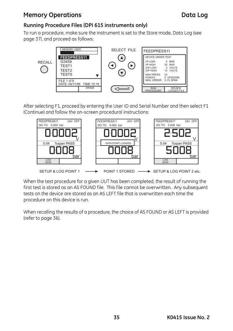
Running Procedure Files (DPI 615 instruments only)To run a procedure, make sure the instrument is set to the Store mode, Data Log (see page 37), and proceed as follows:After selecting F1, proceed by entering the User ID and Serial Number and then select F1 (Continue) and follow the on-screen procedural instructions:
When the test procedure for a given UUT has been completed, the result of running the first test is stored as an AS FOUND file. This file cannot be overwritten. Any subsequent tests on the device are stored as an AS LEFT file that is overwritten each time the procedure on this device is run.
When recalling the results of a procedure, the choice of AS FOUND or AS LEFT is provided (refer to page 36).
G3459FEEDPRESS11
TEST1
TEST5TEST2
ERASE
RECALL
MEMORY USED
FILE 1 of 9DATE: 04/11/99 TIME 10:18
RUNPROCEDURE
REVIEWLOGGED FILE
DEVICE UNDER TEST
I/P LOW:
I/P HIGH
O/P LOW:O/P HIGH
0 BAR
20 BAR
0 VOLTS10 VOLTS
SELECT FILE FEEDPRESS11
MAX PRESS:POINTS:MAX. ERROR:
225 UP/DOWN0.1% SPAN
bar
V
FEEDPRESS11
LOGNOW
..........
%span PASS
GO TO 0.000 bar
0.04
bar
V
FEEDPRESS11 24V OFF
LOGNOW
..........
%span PASS
GO TO 5.000 bar
0.04
bar
V
FEEDPRESS11..........
%span PASS
GO TO 0.000 bar
DATA POINT LOGGED
SETUP & LOG POINT 1 SETUP & LOG POINT 2 etc.POINT 1 STORED
24V OFF24V OFF
35 K0415 Issue No. 2

Memory Operations Data Log
Recalling Data Files (DPI 615 instruments only)Data or results files generated by running procedures are stored in the instrument’s Data Log directory. To recall a data file to the display, ensure that DATA LOG is selected from the SETUP menu and proceed as follows:Use the cursor keys to select either the AS FOUND option or the AS LEFT option for display. AS FOUND is the result of the first run of a procedure and AS LEFT is the result of the last time the procedure was run.Procedure data files can be displayed either as text (stored screens) or in graphical form. To display as text, select the TEXT option (F1) from the directory and proceed as follows from the File Summary menu. Select AUTO STEP (F1) to automatically review each screen at 1 second intervals or use the left or right cursor keys to manually review.
To transmit the selected logged data via the RS232 interface, connect the instrument to a free port on an external PC, ensure that the instrument’s RS232 parameters match those of the PC.
To display logged data in graphical form, on screen, select GRAPH (F2) from the directory and proceed as follows:
bar
V
TASK : P-VDATA LOG
AUTOSTEP
24V OFF
. %span FAIL
DATA POINT5 OF 10
MANUAL REVIEW
TRANSMITFILE
REVIEWLOGGED DATA
USER ID:
SERIAL No.
RESULTS
CLIFF
99127007
FAIL
FEEDPRESS11
MAX PRESS:POINTS:MAX. ERROR:
205 UP/DOWN0.1% SPAN
DIRECTORY
TEXT GRAPH
AS FOUND
AS LEFT
FEEDPRESS11
V
time0
10.007
15:58:55 16:18:23
K0415 Issue No. 2 36

Using Set-up
GeneralSETUP mode is available in all modes except BASIC and permits the changing of the following instrument parameters.• Store Mode - None, Snapshot, Data Log.
• Contrast.
• Settings - Units, Language, RS232 parameters, Powerdown and Calibration Routines (Refer to page 43 for Calibration details).
• Date and Time (Real Time Clock).
• Backlight Management - On, Off and Timed.
Store Mode
Select STORE MODE from the Set-up menu and select required mode as follows:
ContrastSelect CONTRAST from the Set-up menu and proceed as follows:
SELECT OPTIONSTORE MODE
NONESNAPSHOTDATA LOG
SETUP
SETTINGS
DATE & TIME
STORE MODE
CONTRAST
DRY CELL LEVEL
SETUP
SELECT OPTION
37 K0415 Issue No. 2

Using Set-up
Settings - Select Setup OptionTo select one of the SETTINGS options from the set-up menu, proceed as follows:UnitsSelect UNITS from the SETTINGS menu and proceed as follows:
Define Special UnitsSelect UNITS from the SETTINGS menu and select SPECIAL UNITS and proceed as follows:
K0415 Issue No. 2 38

Using Set-up
LanguageSelect the LANGUAGE version required from the SETTINGS menu and proceed as follows:RS232Select RS232 from the SETTINGS Menu and proceed as follows:
Notes:• Communications default settings are shown above.
• If a communications problems occurs at a particular baud rate, change the baud rate on the instrument and PC to a lower rate.
39 K0415 Issue No. 2
Using Set-up
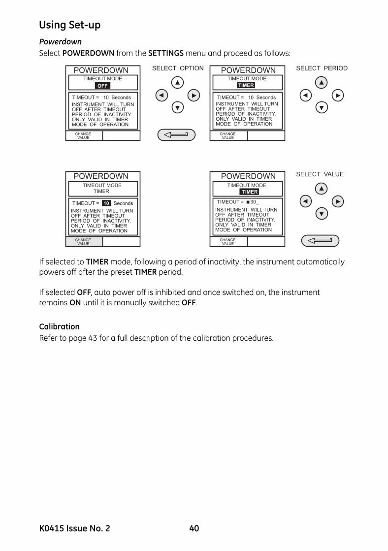
Powerdown Select POWERDOWN from the SETTINGS menu and proceed as follows:If selected to TIMER mode, following a period of inactivity, the instrument automatically powers off after the preset TIMER period.
If selected OFF, auto power off is inhibited and once switched on, the instrument remains ON until it is manually switched OFF.
CalibrationRefer to page 43 for a full description of the calibration procedures.
SELECT OPTION SELECT PERIOD
SELECT VALUE
POWERDOWN
POWERDOWN POWERDOWN
CHANGEVALUE
TIMEOUT MODE
OFF
TIMEOUT = 10 Seconds
INSTRUMENT WILL TURNOFF AFTER TIMEOUTPERIOD OF INACTIVITY.ONLY VALID IN TIMERMODE OF OPERATION
INSTRUMENT WILL TURNOFF AFTER TIMEOUTPERIOD OF INACTIVITY.ONLY VALID IN TIMERMODE OF OPERATION
INSTRUMENT WILL TURNOFF AFTER TIMEOUTPERIOD OF INACTIVITY.ONLY VALID IN TIMERMODE OF OPERATION
INSTRUMENT WILL TURNOFF AFTER TIMEOUTPERIOD OF INACTIVITY.ONLY VALID IN TIMERMODE OF OPERATION
POWERDOWN
CHANGEVALUE
TIMEOUT MODE
TIMER
TIMEOUT = 10 Seconds
CHANGEVALUE
TIMEOUT MODE
TIMER
TIMEOUT =
CHANGEVALUE
TIMEOUT MODE
TIMER
TIMEOUT =10 Seconds 30
K0415 Issue No. 2 40
Using Set-up
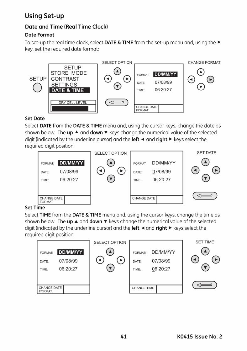
Date and Time (Real Time Clock)Date FormatTo set-up the real time clock, select DATE & TIME from the set-up menu and, using the key, set the required date format:Set Date Select DATE from the DATE & TIME menu and, using the cursor keys, change the date as shown below. The up and down keys change the numerical value of the selected digit (indicated by the underline cursor) and the left and right keys select the required digit position.
Set TimeSelect TIME from the DATE & TIME menu and, using the cursor keys, change the time as shown below. The up and down keys change the numerical value of the selected digit (indicated by the underline cursor) and the left and right keys select the required digit position.
SELECT OPTION CHANGE FORMAT
SETUP
SETUP
SETTINGS
STORE MODECONTRAST
DRY CELL LEVEL
DATE & TIME
CALIBRATION
CHANGE DATEFORMAT
FORMAT:
DATE:
TIME:
DD/MM/YY
07/08/99
06:20:27
SELECT OPTION SET DATE
CALIBRATION
CHANGE DATEFORMAT
FORMAT:
DATE:
TIME:
DD/MM/YY
07/08/99
06:20:27
CHANGE DATE
FORMAT:
DATE:
TIME:
DD/MM/YY
07/08/99
06:20:27
SELECT OPTION SET TIME
CALIBRATION
CHANGE DATEFORMAT
FORMAT:
DATE:
TIME:
DD/MM/YY
07/08/99
06:20:27
CHANGE TIME
FORMAT:
DATE:
TIME:
DD/MM/YY
07/08/99
06:20:27
41 K0415 Issue No. 2
Using Set-up
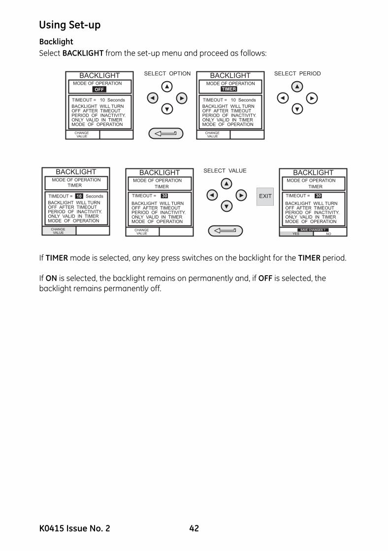
BacklightSelect BACKLIGHT from the set-up menu and proceed as follows:If TIMER mode is selected, any key press switches on the backlight for the TIMER period.
If ON is selected, the backlight remains on permanently and, if OFF is selected, the backlight remains permanently off.
EXIT
SELECT OPTION SELECT PERIODBACKLIGHT
CHANGEVALUE
MODE OF OPERATION
OFF
TIMEOUT = 10 Seconds
BACKLIGHT WILL TURNOFF AFTER TIMEOUTPERIOD OF INACTIVITY.ONLY VALID IN TIMERMODE OF OPERATION
BACKLIGHT
CHANGEVALUE
MODE OF OPERATION
TIMER
TIMEOUT = 10 Seconds
BACKLIGHT WILL TURNOFF AFTER TIMEOUTPERIOD OF INACTIVITY.ONLY VALID IN TIMERMODE OF OPERATION
BACKLIGHT
CHANGEVALUE
MODE OF OPERATION
TIMER
TIMEOUT =
BACKLIGHT WILL TURNOFF AFTER TIMEOUTPERIOD OF INACTIVITY.ONLY VALID IN TIMERMODE OF OPERATION
10 Seconds
SELECT VALUEBACKLIGHT
CHANGEVALUE
MODE OF OPERATION
TIMER
TIMEOUT =
BACKLIGHT WILL TURNOFF AFTER TIMEOUTPERIOD OF INACTIVITY.ONLY VALID IN TIMERMODE OF OPERATION
30
BACKLIGHTMODE OF OPERATION
TIMER
TIMEOUT =
BACKLIGHT WILL TURNOFF AFTER TIMEOUTPERIOD OF INACTIVITY.ONLY VALID IN TIMERMODE OF OPERATION
30
SAVE CHANGES ?
YES NO
K0415 Issue No. 2 42

Calibration
General
The instrument is supplied by the manufacturer, complete with calibration certificate(s). A calibration period of 12 months is recommended. The actual calibration interval depends on instrument usage and the total measurement uncertainty acceptable for the specified application.
The DPI 610 and DPI 615 are very precise measuring instruments and the test equipment and conditions of test must be suitable for the type of work. A Class A compensated deadweight tester must be used. The calibration check and calibration adjustment should be carried out in a controlled environment by a calibration technician*.
The manufacturer offers a comprehensive and, if required, UKAS accredited calibration service.* A calibration technician must have the necessary technical knowledge,
documentation, special test equipment and tools to carry out the calibration work on this equipment.
Calibration CheckAt the chosen calibration interval, the instrument readings should be compared with a known pressure standard. The recommended method starts at 0, increasing in 20% steps to 100% full-scale and then decreasing in 20% steps to 0.Note any deviations between the instrument and the pressure standard and consider traceability (accuracy to a National Standard). If, after a calibration check, the results exceed the tolerance in the specification (or other suitable performance standard), carry out a calibration adjustment.
Calibration Adjustment If the instrument is operating correctly, only zero and full-scale calibration will vary. Any excessive non-linearity or temperature effects indicate a fault. The instrument should be returned to a qualified service agent.
Guide to Calibration Procedures• Use high quality Repeatable and Linear pressure sources and allow adequate
thermal stabilization time before calibration (minimum 1 hour).
• Conduct the calibration in a temperature controlled and preferably, humidity controlled environment. Recommended temperature is 21°C, ±2°C (70°F, ±4°F).
• Use deadweight testers carefully and away from draughts.
• Review and become familiar with the whole calibration procedure before commencing the calibration process.
• The calibration routines cannot be accessed when the instrument is in BASIC mode. Use the TASK key to select another mode (e.g.) ADVANCED before accessing the CALIBRATION mode.
43 K0415 Issue No. 2

Calibration
Test EquipmentThe calibration procedures require the following test equipment.*ppm = parts per million
Table 1 Internal/External Pressure Transducer Verification
PC* = Pressure Calibrator HC* = Hydraulic Calibrator LP* = Low Pressure Calibrator
Test Equipment and Instrument Parameter/RangeCalibrationEquipmentAccuracy
Calibration Uncertainty
Digital Voltmeter - 5V input ±30 *ppm ±1 digit ±10 *ppm ±5µV
Digital Voltmeter - 50V input ±45 *ppm ±1 digit ±11 *ppm ± 110 µV
Digital milliammeter - 55mA input ±150 *ppm ±4 digit ±100 *ppm ± 1nA
Digital milliammeter - 24mA output ±150 *ppm ±4 digit ±160 *ppm ± 1nA
Precision thermometer - ambient temperature ±0.2°C ± 0.1°C ±1 digit
Deadweight tester - pressure internal/external Class A deadweight <0.025%
Nominal applied value as a% of ±full-scale
Permissible deviation
PC*, HC* and Indicator Versions
LP* Versions and external LPE 9400
sensors
0% (10% for absolute ranges) ± 0.025% FS ± 0.05% span20% ± 0.025% FS ± 0.05% span40% ± 0.025% FS ± 0.05% span60% ± 0.025% FS ± 0.05% span80% ± 0.025% FS ± 0.05% span
100% ± 0.025% FS ± 0.05% span80% ± 0.025% FS ± 0.05% span60% ± 0.025% FS ± 0.05% span40% ± 0.025% FS ± 0.05% span20% ± 0.025% FS ± 0.05% span
0% (10% for absolute ranges) ± 0.025% FS ± 0.05% span
K0415 Issue No. 2 44

Calibration
Using the Calibration MenuThe calibration routines are selected from the Settings menu as detailed on page 38. Enter the calibration PIN number, initially set to 4321, press and the display shows the Calibration Menu.PIN securityTo prevent unauthorised access, it is recommended that the PIN number be changed as soon as possible.Change PINTo change the PIN code, select CHANGE PIN from the calibration menu and proceed as follows:
Note: To set and verify a new PIN, the new PIN code must be entered twice.
• If the second code entered differs from the first, the new PIN will not be set.
Calibrate Internal Ranges
Select the INT RANGES from the menu as shown above and follow the calibration procedure on the display.
SELECT OPTIONCALIBRATION
EXT SENSORS
CHANGE PIN
INT RANGES
V v t
SET NEW PIN SET NEW PIN AGAIN
Enter New PIN
5 4 3 2
Enter New PIN
45 K0415 Issue No. 2

Calibration
Internal Pressure RangeUse the following procedure for calibrating the internal pressure range.Note: If calibrating the hydraulic calibrator version, the calibrator must first be primed asdetailed on pages 59 to 66. (1) Connect the outlet port of the instrument to a pressure standard.(2) Allow the instrument’s temperature to stabilize for a minimum of 1 hour.(3) Switch the instrument on, enter CALIBRATION mode and select INT RANGES from
the CALIBRATION menu and then PRESSURE INT.
(4) Apply zero pressure and store the zero point:
(5) Close the vent valve, apply full-scale pressure and store the full-scale point:
(6) Press the ENTER key to accept the calibration. Press the EXIT key four times to quit CALIBRATION and SETUP modes.
(7) Check calibration by applying test pressures in Table 1, page 44.
VOLTAGE IN
K0415 Issue No. 2 46

Calibration
Voltage Input Range (5 Volts)Use the following procedure for calibrating the internal 5 Volt range.(1) Switch the instrument on, enter CALIBRATION mode and select INT RANGES fromthe CALIBRATION menu as shown on page 45.
(2) Select 5V range for calibration:
(3) Link the voltage input terminals with a short lead and enter the zero point:
(4) Remove the shorting link from the voltmeter terminals, connect the Vin terminals of the instrument to a variable voltage source and connect a digital voltmeter across the source:
SELECT OPTION SELECT OPTIONSELECT RANGE
50 VOLTS
5 VOLTS
CALIBRATION
VOLTAGE IN
CURRENT IN
CURRENT OUT
PRESSURE INT
TEMPERATURE
47 K0415 Issue No. 2

Calibration
(5) Set the variable supply voltage to 5V ± 0.1V and enter the measured full-scalevoltage applied:
(6) Press the ENTER key to accept the calibration. Press the EXIT key once to return to the calibration menu or four times to quit the CALIBRATION and SETUP modes.
(7) Verify the instrument calibration by applying the test voltages given in Table 2 (page 50), to the voltmeter (after both voltage ranges have been calibrated).
(8) Disconnect the calibration/test equipment.
K0415 Issue No. 2 48

Calibration
Voltage Input Range (50 Volts)Use the following procedure for calibrating the internal 50 Volt range.(1) Switch the instrument on, enter CALIBRATION mode and select INT RANGES fromthe CALIBRATION menu as shown on Page 45.
(2) Select 50V range for calibration:
(3) Link the voltage input terminals with a short lead and enter the zero point:
(4) Remove the shorting link from the voltmeter terminals, connect the Vin terminals of the instrument to a variable voltage source and connect a digital voltmeter across the source:
49 K0415 Issue No. 2

Calibration
(5) Set the variable supply voltage to 50V ± 0.1V and enter the measured full-scalevoltage:
(6) Press the ENTER key to accept the calibration. Press the EXIT key four times to quit the CALIBRATION and SETUP modes.
(7) Verify the instrument calibration by applying the test voltages given in Table 2 to the voltmeter (after both voltage ranges have been calibrated).
(8) Disconnect the calibration/test equipment.
Table 2 Electrical Voltage Input Calibration Tolerances
Voltage Calibration 50V Range Verification Tolerances Voltage Calibration 5V Range Verification Tolerances
Applied Voltage Permissible Deviation Applied Voltage Permissible Deviation
-50 ± 0.05% rdg, ± 0.004% FS -5 ± 0.05% rdg, ± 0.004% FS-40 ± 0.05% rdg, ± 0.004% FS -4 ± 0.05% rdg, ± 0.004% FS-30 ± 0.05% rdg, ± 0.004% FS -3 ± 0.05% rdg, ± 0.004% FS-20 ± 0.05% rdg, ± 0.004% FS -2 ± 0.05% rdg, ± 0.004% FS-10 ± 0.05% rdg, ± 0.004% FS -1 ± 0.05% rdg, ± 0.004% FS0 ± 0.05% rdg, ± 0.004% FS 0 ± 0.05% rdg, ± 0.004% FS
10 ± 0.05% rdg, ± 0.004% FS 1 ± 0.05% rdg, ± 0.004% FS20 ± 0.05% rdg, ± 0.004% FS 2 ± 0.05% rdg, ± 0.004% FS30 ± 0.05% rdg, ± 0.004% FS 3 ± 0.05% rdg, ± 0.004% FS40 ± 0.05% rdg, ± 0.004% FS 4 ± 0.05% rdg, ± 0.004% FS50 ± 0.05% rdg, ± 0.004% FS 5 ± 0.05% rdg, ± 0.004% FS
K0415 Issue No. 2 50

Calibration
Current Input Range (55 mA)Use the following procedure for calibrating the current input range.(1) Switch the instrument on, enter CALIBRATION mode and select INT RANGES fromthe CALIBRATION menu as shown on Page 45.
(2) Select CURRENT IN range for calibration:
(3) Open circuit the mA in terminals and enter the zero point:
(4) Connect the mA in terminals of the instrument to a variable current source and connect a digital milliammeter in series with the supply:
MILLIAMMETER
51 K0415 Issue No. 2

Calibration
(5) Set the input current to 55 ± 0.1mA and enter the measured full-scale inputcurrent:
(6) Press the ENTER key to accept the calibration. Press the EXIT key four times to quit the CALIBRATION and SETUP modes.
(7) Verify the instrument calibration by applying the test currents given in Table 3 to the milliammeter.
(8) Disconnect the calibration/test equipment.
Table 3 Electrical Current Input Calibration Tolerances
Current Calibration, 55mA Range Verification Tolerances
Applied Current (mA) Permissible Deviation
-55 ± 0.05% rdg ± 0.004% FS-45 ± 0.05% rdg ± 0.004% FS-35 ± 0.05% rdg ± 0.004% FS-25 ± 0.05% rdg ± 0.004% FS-15 ± 0.05% rdg ± 0.004% FS-5 ± 0.05% rdg ± 0.004% FS0 ± 0.05% rdg ± 0.004% FS5 ± 0.05% rdg ± 0.004% FS
15 ± 0.05% rdg ± 0.004% FS25 ± 0.05% rdg ± 0.004% FS35 ± 0.05% rdg ± 0.004% FS45 ± 0.05% rdg ± 0.004% FS55 ± 0.05% rdg ± 0.004% FS
K0415 Issue No. 2 52

Calibration
Current Output Range (24 mA)Use the following procedure for calibrating the current output range.(1) Switch the instrument on, enter CALIBRATION mode and select INT RANGES from the CALIBRATION MENU as shown on page 45.
(2) Select CURRENT OUT range for calibration:
(3) Connect a digital milliammeter to the instrument as shown below.
Note: On standard instruments, during a current out calibration routine, the 24V dc output is automatically turned on.
mA
53 K0415 Issue No. 2
Calibration
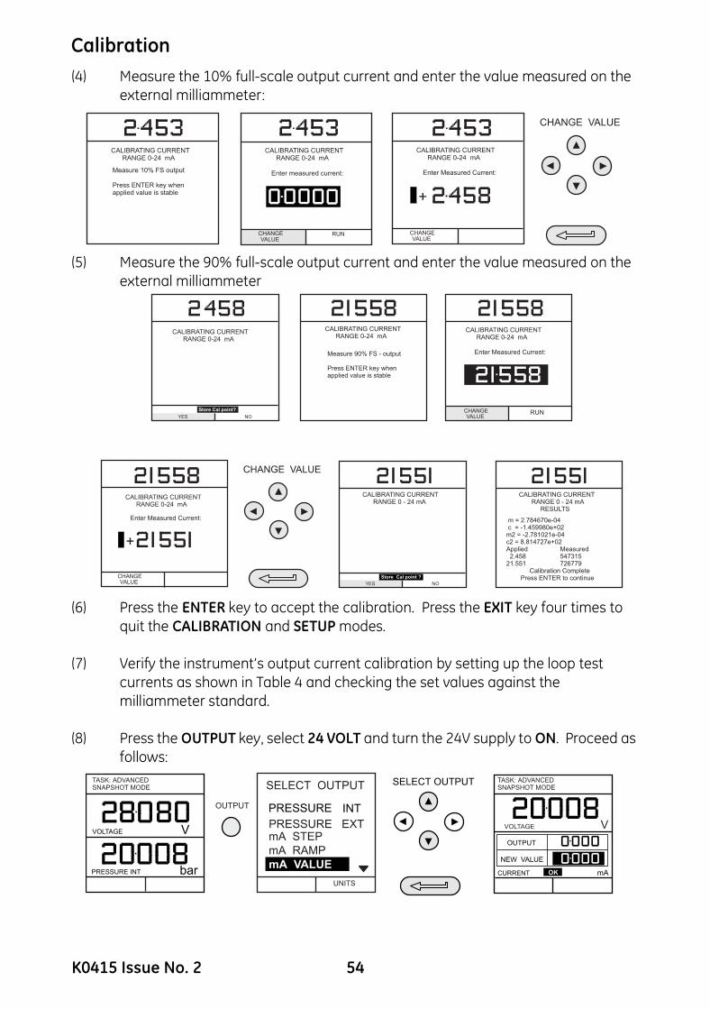
(4) Measure the 10% full-scale output current and enter the value measured on theexternal milliammeter:
(5) Measure the 90% full-scale output current and enter the value measured on the external milliammeter
(6) Press the ENTER key to accept the calibration. Press the EXIT key four times to quit the CALIBRATION and SETUP modes.
(7) Verify the instrument’s output current calibration by setting up the loop test currents as shown in Table 4 and checking the set values against the milliammeter standard.
(8) Press the OUTPUT key, select 24 VOLT and turn the 24V supply to ON. Proceed as follows:
Measure 90% FS - output
Press ENTER key whenapplied value is stable
Store Cal point?
YES NO
Enter Measured Current:
RUN
:
K0415 Issue No. 2 54
Calibration
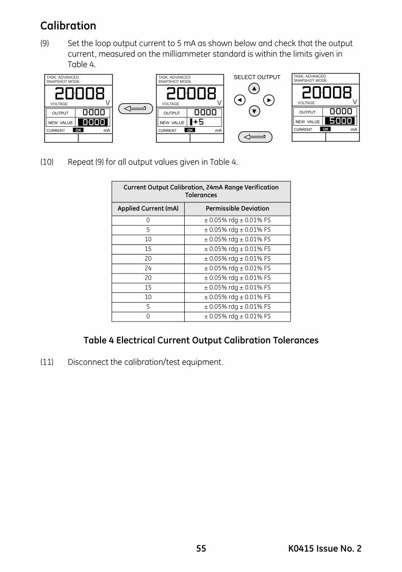
(9) Set the loop output current to 5 mA as shown below and check that the outputcurrent, measured on the milliammeter standard is within the limits given in Table 4.
(10) Repeat (9) for all output values given in Table 4.
Table 4 Electrical Current Output Calibration Tolerances
(11) Disconnect the calibration/test equipment.
Current Output Calibration, 24mA Range Verification Tolerances
Applied Current (mA) Permissible Deviation
0 ± 0.05% rdg ± 0.01% FS5 ± 0.05% rdg ± 0.01% FS
10 ± 0.05% rdg ± 0.01% FS15 ± 0.05% rdg ± 0.01% FS20 ± 0.05% rdg ± 0.01% FS24 ± 0.05% rdg ± 0.01% FS20 ± 0.05% rdg ± 0.01% FS15 ± 0.05% rdg ± 0.01% FS10 ± 0.05% rdg ± 0.01% FS5 ± 0.05% rdg ± 0.01% FS0 ± 0.05% rdg ± 0.01% FS
55 K0415 Issue No. 2

Calibration
Ambient Temperature ChannelUse the following procedure for calibrating the ambient temperature measurement channel.(1) Switch the instrument on, enter the CALIBRATION mode and selectTEMPERATURE:
(2) Allow the instrument’s temperature to stabilize in the calibration environment for at least one hour.
(3) Read the environmental temperature on a calibrated digital thermometer and enter the recorded value as shown below. Example shown for a measured ambient temperature of 21.5° Celsius.
Note: Only one temperature point is required.
(4) Press the ENTER key to accept the calibration. Press the EXIT key once to return to the calibration menu or four times to quit the CALIBRATION and SETUP modes.
K0415 Issue No. 2 56

Calibration
Calibrate External SensorsUse the following procedure for calibrating external pressure sensors.(1) Connect the required external transducer to the EXT TRANSDUCER socket located on the rear of the instrument.
(2) Allow the instrument’s temperature and the temperature of the external transducer to stabilize in the calibration environment for a minimum of 1 hour.
(3) Switch the instrument on, enter CALIBRATION mode and select EXT SENSORS from the CALIBRATION menu:
(4) Select the transducer to be calibrated from the transducer menu using the cursor keys and press ENTER:
If the sensor to be calibrated is not in the directory, or no sensors are listed in the directory, press the F1 key (ADD NEW SENSOR). This will place the sensor in the directory, allowing it to then be selected.
(5) Connect the pressure standard to the inlet of the external transducer, apply the zero point pressure and store the zero point:
INT RANGES
CHANGE PIN
EXT SENSORS
57 K0415 Issue No. 2

(6) Apply the full-scale pressure to the external transducer and store the full-scale (FS) point.
(7) Release the applied pressure and disconnect the pressure reference. Press the ENTER key to accept the calibration. Press the EXIT key once to return to the calibration menu or four times to quit the CALIBRATION and SETUP modes.
(8) Check the calibration of the external transducer by applying the test pressures as detailed in Table 1, page 44.
Add External SensorTo add an external sensor to the directory of external sensors, proceed as follows:
• Connect the required external transducer to the EXT TRANSDUCER socket located on the rear of the instrument.
Digitally compensated transducers will be downloaded into the directory as soon as the F1 key is operated. Data for other types can be edited by selecting EDIT (F2). If the data cannot be edited a warning message (INVALID ACTION) is displayed.
CALIBRATING PRESSURE EXTRANGE 20000 kPa g
CALIBRATING PRESSURE EXTRANGE 20000 kPa g
CALIBRATING PRESSURE EXTRANGE 20000 kPa g
Apply nominal FS value
Press ENTER key whenapplied value is stable +
CHANGE VALUE
K0415 Issue No. 2 58
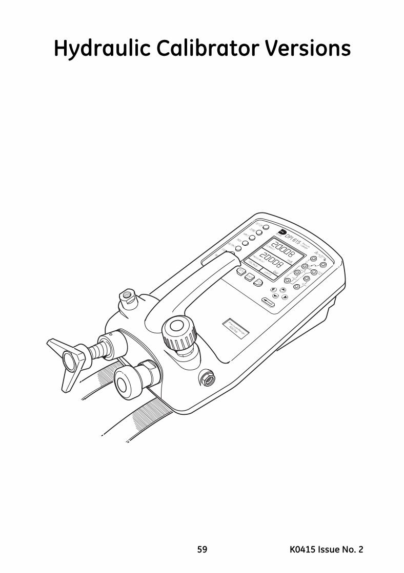
Hydraulic Calibrator Versions
59 K0415 Issue No. 2

This page intentionally left blank
K0415 Issue No. 2 60
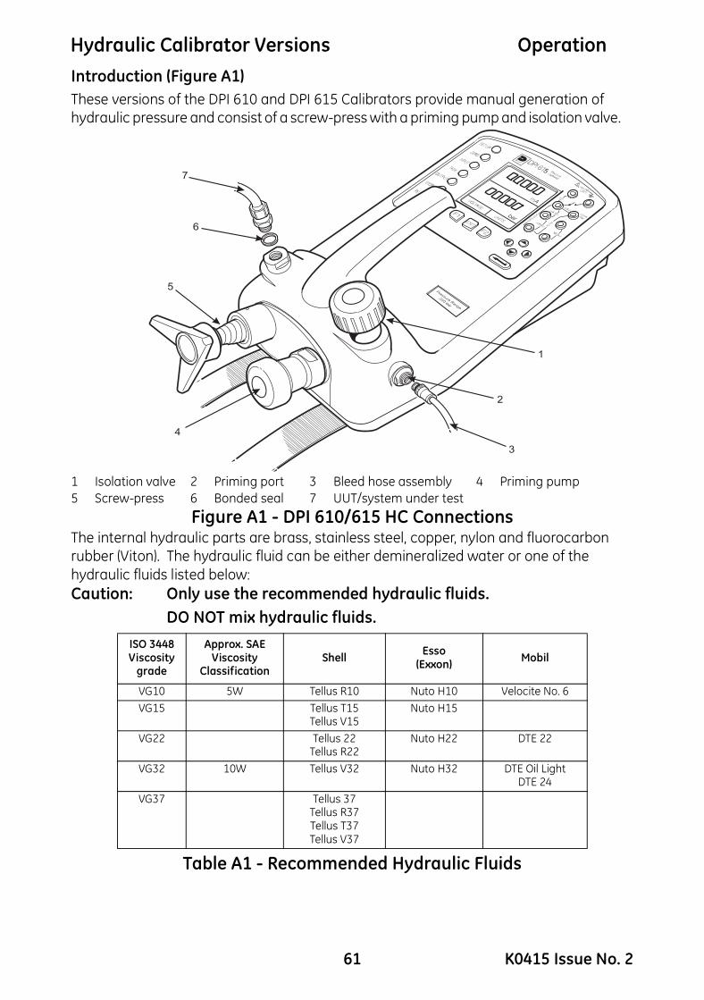
Hydraulic Calibrator Versions Operation
Introduction (Figure A1)These versions of the DPI 610 and DPI 615 Calibrators provide manual generation of hydraulic pressure and consist of a screw-press with a priming pump and isolation valve.1 Isolation valve 2 Priming port 3 Bleed hose assembly 4 Priming pump5 Screw-press 6 Bonded seal 7 UUT/system under test
Figure A1 - DPI 610/615 HC ConnectionsThe internal hydraulic parts are brass, stainless steel, copper, nylon and fluorocarbon rubber (Viton). The hydraulic fluid can be either demineralized water or one of the hydraulic fluids listed below:Caution: Only use the recommended hydraulic fluids.
DO NOT mix hydraulic fluids.
Table A1 - Recommended Hydraulic Fluids
ISO 3448Viscosity
grade
Approx. SAE Viscosity
ClassificationShell Esso
(Exxon) Mobil
VG10 5W Tellus R10 Nuto H10 Velocite No. 6VG15 Tellus T15
Tellus V15Nuto H15
VG22 Tellus 22Tellus R22
Nuto H22 DTE 22
VG32 10W Tellus V32 Nuto H32 DTE Oil LightDTE 24
VG37 Tellus 37Tellus R37Tellus T37Tellus V37
7
6
5
4
1
2
3
5
61 K0415 Issue No. 2

Hydraulic Calibrator Versions Operation
Safety InstructionsWARNINGHYDRAULIC FLUID IS INJURIOUS. OBSERVE RELEVANT HEALTH AND SAFETY PRECAUTIONS. USE APPROPRIATE PROTECTIVE BARRIERS AND EYE PROTECTION.BEFORE APPLYING PRESSURE, EXAMINE ALL FITTINGS AND EQUIPMENT FOR DAMAGE AND ENSURE THAT ALL EQUIPMENT IS TO THE CORRECT PRESSURE RATING.DO NOT EXCEED THE MAXIMUM WORKING PRESSURE OF THE INSTRUMENT (INDICATED ON START-UP SCREEN AT SWITCH-ON).Caution: Observe absolute cleanliness when using the instrument.Severe damage can be caused if equipment connected to this instrument is contaminated. Connect only clean equipment to the instrument. To avoid any contamination, an external filter is recommended.
Preparation for Use (Figure A1)• Use an appropriate seal and connect the bleed hose assembly (3) to the priming port.
• Make sure that the screw-press (5) is wound fully in (clockwise).
• Make sure that the isolation valve (1) is open (fully counter clockwise).
• Use a bonded seal (6) and connect the unit or system under test (7) to the pressure port.
WARNINGMAKE SURE THAT THE CONNECTING LINE TO THE EXTERNAL DEVICE OR SYSTEM IS CAPABLE OF WITHSTANDING THE LINE PRESSURE TO BE APPLIED.
Note: A bleed point must be provided on the external device.
K0415 Issue No. 2 62
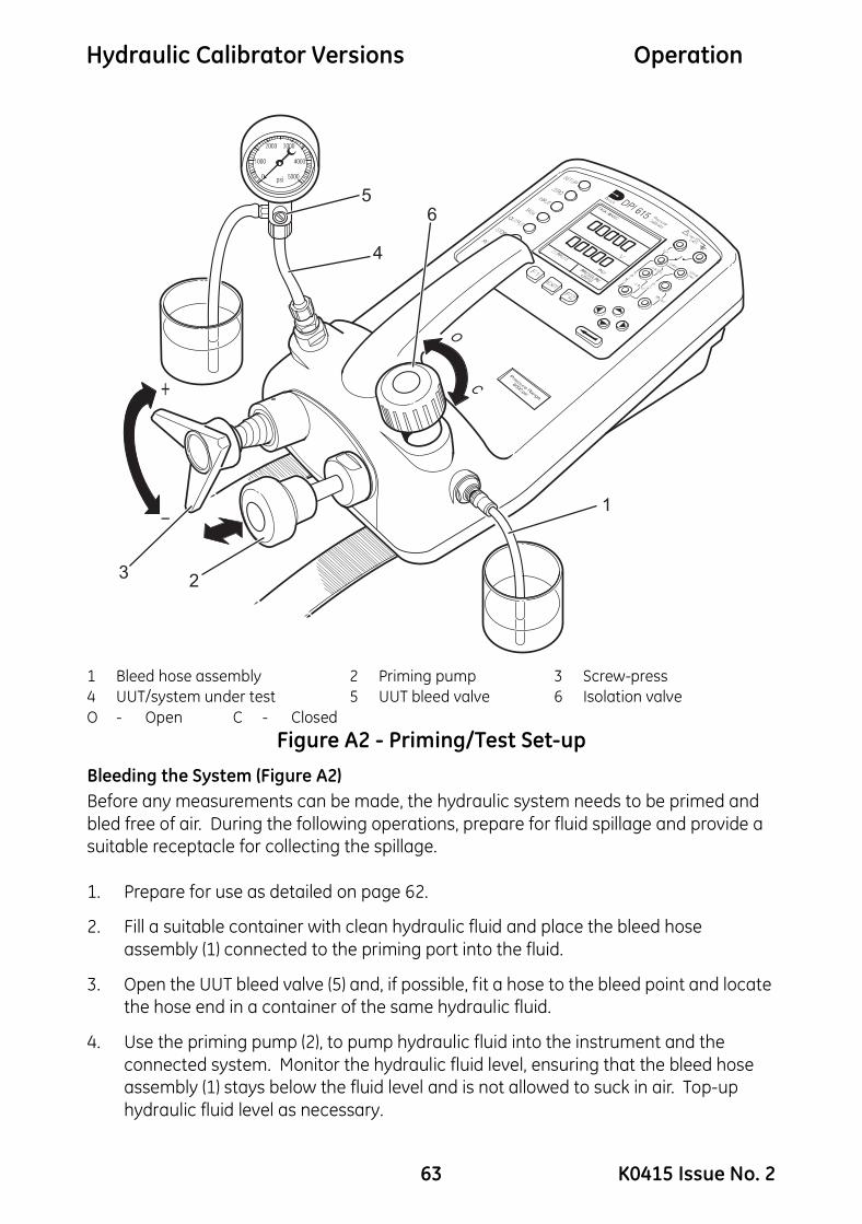
Hydraulic Calibrator Versions Operation
1 Bleed hose assembly 2 Priming pump 3 Screw-press4 UUT/system under test 5 UUT bleed valve 6 Isolation valveO - Open C - Closed
Figure A2 - Priming/Test Set-upBleeding the System (Figure A2)Before any measurements can be made, the hydraulic system needs to be primed and bled free of air. During the following operations, prepare for fluid spillage and provide a suitable receptacle for collecting the spillage.
1. Prepare for use as detailed on page 62.
2. Fill a suitable container with clean hydraulic fluid and place the bleed hose assembly (1) connected to the priming port into the fluid.
3. Open the UUT bleed valve (5) and, if possible, fit a hose to the bleed point and locate the hose end in a container of the same hydraulic fluid.
4. Use the priming pump (2), to pump hydraulic fluid into the instrument and the connected system. Monitor the hydraulic fluid level, ensuring that the bleed hose assembly (1) stays below the fluid level and is not allowed to suck in air. Top-up hydraulic fluid level as necessary.
5
4
6
1
23
63 K0415 Issue No. 2

Hydraulic Calibrator Versions Operation
5. Continue use of the priming pump (2) until only hydraulic fluid and no air is expelledfrom the bleed point.
6. Close the UUT bleed valve (5) when the priming pump (2) is at the bottom of its stroke (fully pushed in) and slowly wind out the screw-press (3) to its fullest extent to draw in further hydraulic fluid (approx. 7cc or 0.43 in3).
7. Switch the instrument ON and, still using the priming pump (2), pressurize the system to approximately 2 bar (30 psi).
8. Close the isolation valve (6) disconnect the bleed hose assembly (1) from the priming port.
OperationTo obtain a pressure reading, proceed as follows.1. Switch the instrument ON and select the required TASK.
2. Rotate the screw-press clockwise to increase the applied pressure.
Note: When hydraulic fluid is compressed and flows through a restriction, there is an increase in temperature that affects the pressure. Allow sufficient time for this pressure reading to stabilize before recording or logging a reading.
3. After testing, reduce the pressure in the system to zero by turning the screw-press counter clockwise. Before disconnecting the UUT, open the isolation valve.
4. Remove the connection to the UUT and fit a blanking plug into the instrument’s pressure port. Clean any spilt fluid off the instrument case.
Draining the Hydraulic Fluid (Figure A3)To drain the hydraulic fluid from the instrument, proceed as follows:
1. Turn the isolation valve (4) fully counter clockwise. Turn the instrument onto the left hand side (pressure port nearest to the work bench). Place receptacle below the pressure port to collect hydraulic fluid.
2. Drain the system by slowly winding in the screw-press (3) and then depressing the priming pump (2) plunger to expel any fluid remaining in the instrument.
3. If necessary, apply an air line to the priming port to clear any remaining fluid out of the instrument.
K0415 Issue No. 2 64
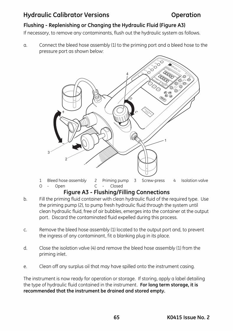
Hydraulic Calibrator Versions Operation
Flushing - Replenishing or Changing the Hydraulic Fluid (Figure A3)If necessary, to remove any contaminants, flush out the hydraulic system as follows.a. Connect the bleed hose assembly (1) to the priming port and a bleed hose to the pressure port as shown below:
1 Bleed hose assembly 2 Priming pump 3 Screw-press 4 Isolation valveO - Open C - Closed
Figure A3 - Flushing/Filling Connectionsb. Fill the priming fluid container with clean hydraulic fluid of the required type. Use
the priming pump (2), to pump fresh hydraulic fluid through the system until clean hydraulic fluid, free of air bubbles, emerges into the container at the output port. Discard the contaminated fluid expelled during this process.
c. Remove the bleed hose assembly (1) located to the output port and, to prevent the ingress of any contaminant, fit a blanking plug in its place.
d. Close the isolation valve (4) and remove the bleed hose assembly (1) from the priming inlet.
e. Clean off any surplus oil that may have spilled onto the instrument casing.
The instrument is now ready for operation or storage. If storing, apply a label detailing the type of hydraulic fluid contained in the instrument. For long term storage, it is recommended that the instrument be drained and stored empty.
1
4
2
3
65 K0415 Issue No. 2

This page intentionally left blank
K0415 Issue No. 2 66

Low Pressure Calibrator Versions
67 K0415 Issue No. 2

This page intentionally left blank
K0415 Issue No. 2 68

Low Pressure Calibrator Versions
Introduction (Figure B1)These versions of the DPI 610 and DPI 615 Calibrator measure and display low differential pneumatic pressures applied to the pressure port. The differential pressure measurement ranges can be: 2.5, 12.5, 25, 50, 75 or 150 mbar (1.0, 5.0, 10.0, 20.0, 30.0 and 60.0 inH2O). For low volume external systems or devices, test pressures are generated by an integral two-stage (coarse/fine) volume adjuster. For larger volume external systems or devices, test pressures are generated by an external, hand-operated, pneumatic pump.An internal pressure limiter operates at 120% of the full-scale, positive or negative test pressure. If this over-pressure remains for more than approximately 1 second, a valve within the calibrator opens, directly connecting the positive and negative pressure ports together, to release the excess pressure. When the pressure decreases to within the operational limits, the valve automatically closes to allow normal operation to restart.
This section should be read in conjunction with the operation and calibration sections of this manual. All the operational features described for the standard calibrator are available on this low pressure version of the calibrator.
1 Control panel 2 Vent valve 3 Positive pressure output port4 Volume adjuster (fine) 5 Volume adjuster (coarse) 6 Reference port
Figure B1 - Calibrator Controls
1
2
6
5
4
3
69 K0415 Issue No. 2

Preparation for Use Low Volume SystemsCaution: This calibrator can produce a maximum differential pressure of 120%
full-scale. Make sure any component connected to this calibrator can withstand this maximum differential pressure.
• Use the TASK key to set-up the calibrator for an appropriate test:
Example:P-DISPLAY.
• To record test data for other tasks, set-up the calibrator to either Data log or Snapshot as required, refer to pages 30 or 31.
• Fit an appropriate pressure fitting to both the positive (+) and negative (-) ports using a bonded seal as shown in Figure B2. Ensure that both fittings are tight.
• To generate pressure, start with the volume adjuster wound fully out.
• To generate vacuum, start with the volume adjuster wound fully in.
• Ensure that the vent valve is open (fully counter-clockwise).
• Connect the device or system under test to both the reference (-) and the pressure port (+). Connect the ribbed arm of the double tubing to the high (+) pressure input of the device under test.
Note: To minimize temperature effects, always use double tubing, separating the arms of the tubing only by the minimum amount necessary to make the pressure connections. A typical application, P-DISPLAY, showing test connections to a Magnehelic pressure gauge are shown in Figure B2.
Method of Testing with Low Volume Systems• Connect the device under test to the calibrator and prepare for test as detailed
above.
• Close the vent valve (turn fully clockwise).
• Zero the calibrator by pressing the ZERO key as in the sequence below:
ZERO
TASK: P-DISPLAY
mbarCHANGE
VALUE
TASK: P-DISPLAY
DISPLAY DISPLAY DISPLAY
24V OFF
mbar
YESZERO INTERNAL SENSOR ?
NO
24V OFF
mbarPLEASE WAIT . . .
TASK: P-DISPLAY 24V OFF
K0415 Issue No. 2 70

Low Pressure Calibrator Versions
C - Closed O - Open
Figure B2 - Test Connections
71 K0415 Issue No. 2

Method of Testing with Low Volume Systems (continued)• Turn the volume adjuster coarse control clockwise (counter-clockwise for
vacuum) to set-up the required test pressure. Use the volume adjuster fine control to adjust the test pressure of the calibrator to exactly the required value.
• Use the TASK key to set-up the calibrator for an appropriate test:
Example:P-DISPLAY
• To record test data for other tasks, set-up the calibrator to either Data log or Snapshot as required (refer to pages 30 or 31). If required, and for DPI 615 calibrators only, switch on Cal Mode (refer to pages 11, 34 and 35).
• Turn the volume adjuster clockwise to set-up any additional test pressures required. The recommended method starts at 0, increasing to 10%, 25%, 50%, 75% and 100% full-scale and then decreasing to 75%, 50%, 25%, 10% and 0.
Note: To release the output pressure at any point during a test or series of tests, open the vent valve. Allow sufficient time for the connected system to vent (very important when connected to larger system volumes, >0.25 litres [15 cubic inches]).
Preparation for Use with Larger Volume Systems• Set-up the calibrator to record the test data, using either Data log or Snapshot
facilities refer to pages 30 or 31. If required, and for DPI 615 calibrators only, switch on Cal Mode (refer to pages 11, 34 and 35).
• Fit the appropriate pressure fitting to both the positive (+) and negative (-) ports using a bonded seal as shown in Figure B3. Make sure that both pressure fittings are tight.
• Turn the volume adjuster (counter-clockwise) to approximately half-way (approximately 30mm (1”) of thread showing).
• Make sure that the vent valve is open (fully counter-clockwise).
• Connect the hand-pump and tee-piece as shown in Figure B3. Connect the device or system under test to both the reference (-) and the pressure port (+) as shown. Connect the ribbed arm of the double tubing to the high (+) pressure input of the device under test.
Note: To minimize temperature effects, always use double tubing, separating the arms of the tubing only by the minimum amount necessary to make the pressure connections. See Figure B3.
K0415 Issue No. 2 72

Low Pressure Calibrator Versions
1 - To device/system under test C - Closed2 - Tee-piece inserted in positive output line O - Open
Figure B3 - Hand-pump Connections
.
+1
2
73 K0415 Issue No. 2

Method of Testing with Larger Volume Systems• Connect the device or external system under test to the calibrator and prepare
for test as detailed on Page 72.
Note: To apply a negative differential pressure, connect the tee piece (refer to Figure B3), to the negative port and use the hand-pump to apply a positive pressure to the negative port.
• Close the vent valve (turn fully clockwise).
• Zero the calibrator by pressing the ZERO key as in the sequence below:
CAUTION: TO AVOID THE APPLICATION OF TRANSIENT OVER-PRESSURE PULSES TO SENSITIVE EXTERNAL SYSTEMS, SQUEEZE THE HAND-PUMP SLOWLY.
• Close the pump valve and operate the hand-pump to pressurize or depressurize the device or system under test to just above/below the required level.
• Adjust the output pressure to the required level by using the volume adjuster as a fine adjustment. Allow a short period for the pressure to stabilize before fine trimming.
Note: The larger the external volume, the less effect the volume adjuster will have on the output pressure.
• Record the test result using either data log or snapshot facility as required.
• Use the pump and volume adjuster to set-up any additional test pressures required. The recommended method starts at 0, increasing to 10%, 25%, 50%, 75% and 100% full-scale and then decreasing to 75%, 50%, 25%, 10% and 0. Record the results for each test pressure.
Note: To release the output pressure at any point during a test or series of tests, open the vent valve. Allow a few seconds for the connected system to vent. With larger volume systems connected, first disconnect both the reference and positive pressure lines from the calibrator and then reconnect before zeroing.
ZERO
TASK: P-DISPLAY
mbarCHANGE
VALUE
TASK: P-DISPLAY
DISPLAY DISPLAY DISPLAY
24V OFF
mbar
YESZERO INTERNAL SENSOR ?
NO
24V OFF
mbarPLEASE WAIT . . .
TASK: P-DISPLAY 24V OFF
K0415 Issue No. 2 74

Low Pressure Calibrator Versions
CalibrationThe calibration routines for the DPI 610 and DPI 615 Low Pressure calibrators are as described in calibration page 43, with the exception of the internal pressure range. The calibration procedure for the internal pressure range requires the application of five test pressures as detailed below.
Note: Refer to page 43 for the general procedures of calibrating the instrument. Refer to Table 1, page 44 for the transducer verification.
Calibrate Internal Pressure RangeTo calibrate the internal pressure range:• Connect the outlet port of the instrument to a pressure standard.
• Switch the instrument ON.
• Allow at least one hour for the temperature of the instrument to stabilize.
• Select SETUP and enter the SETTINGS menu.
Note: SETUP cannot be selected from BASIC mode.• Select CALIBRATION from the SETTINGS menu and enter the calibration PIN
number (refer to page 45 for PIN number details).
• Select PRESSURE INT from the CALIBRATION menu (refer to page 46).
• Apply negative full-scale pressure to the instrument. Store the negative full-scale point:
• Apply negative, half full-scale pressure to the instrument and store the negative half full-scale point:
CALIBRATING PRESSURE INTRANGE 2.5000 mbar L
CALIBRATING PRESSURE INTRANGE 2.5000 mbar L
CALIBRATING PRESSURE INTRANGE 2.5000 mbar L
Apply -ve F.S. value
ENTER VALUE
CHANGEVALUE
Enter Applied Value:
Store -ve F.S. point ?
YES NO
Press ENTER key whenapplied value is stable
CALIBRATING PRESSURE INTRANGE 2.5000 mbar L
CALIBRATING PRESSURE INTRANGE 2.5000 mbar L
CALIBRATING PRESSURE INTRANGE 2.5000 mbar L
Apply half -ve F.S. value
ENTER VALUE
CHANGEVALUE
Enter Applied Value:
Store half -ve F.S. point ?
YES NO
Press ENTER key whenapplied value is stable
75 K0415 Issue No. 2

• Apply a nominal zero pressure to the instrument and store the zero point:
• Apply the positive, half full-scale pressure to the instrument and store the positive, half full-scale point:
• Apply positive full-scale pressure to the instrument and store the full-scale point:
• After application of the final calibration pressure, the calibration results are displayed as shown below. To view the second page of calibration data press MORE (F1). Press ENTER to complete the pressure calibration procedure.
CALIBRATING PRESSURE INTRANGE 2.5000 mbar L
CALIBRATING PRESSURE INTRANGE 2.5000 mbar L
CALIBRATING PRESSURE INTRANGE 2.5000 mbar LENTER VALUE
CHANGEVALUE
Enter Applied Value:
Store zero point ?
YES NO
Apply nominal zero value
Press ENTER key whenapplied value is stable
CALIBRATING PRESSURE INTRANGE 2.5000 mbar L
CALIBRATING PRESSURE INTRANGE 2.5000 mbar L
CALIBRATING PRESSURE INTRANGE 2.5000 mbar L
Apply half +ve F.S. value
ENTER VALUE
CHANGEVALUE
Enter Applied Value:
Store half +ve F.S. point ?
YES NO
Press ENTER key whenapplied value is stable
CALIBRATING PRESSURE INTRANGE 2.5000 mbar L
CALIBRATING PRESSURE INTRANGE 2.5000 mbar L
CALIBRATING PRESSURE INTRANGE 2.5000 mbar L
Apply nominal F.S. value
ENTER VALUE
CHANGEVALUE
Enter Applied Value:
Store +ve F.S. point ?
YES NO
Press ENTER key whenapplied value is stable
CALIBRATING PRESSURE INTRANGE 2.5000 mbar L
CALIBRATING PRESSURE INTRANGE 2.5000 mbar L
RESULTSRESULTSa= 1.632719e-13b= -7.546076e-06c= 3.915159e+00Applied Measured0.0000 5231661.2500 3542052.5000 182699
Calibration completePress ENTER to continue
a= 1.47115e-14b= -7.546076e-06c= 3.808651e+00Applied Measured-2.5000 865995-1.2500 6946380.0000 523166
Calibration completePress ENTER to continue
MORE MORE
K0415 Issue No. 2 76

Appendix 1
DATA LOG FILE EXAMPLE
77 K0415 Issue No. 2

This page intentionally blank
K0415 Issue No. 2 78

Typical Uploaded Data log File (DPI 610)The following gives details of a typical data file upload.
FILENAME: TEST 5DATE: 05/11/1999TIME: 15:58TRIGGER: KEYPRESSAMBIENT TEMP : 24.1 C
NO. OF POINTS 11RECORD TYPE 0CURRENT mA PRESSURE INT bar
3.902 0.008 -0.65 %span 05/11/1999 15:58:55 6.076 2.311 1.42 %span 05/11/1999 16:00:03 7.598 4.404 0.47 %span 05/11/1999 16:00:57 8.085 5.023 0.41 %span 05/11/1999 16:01:45 9.949 7.249 0.94 %span 05/11/1999 16:02:42 13.002 11.300 -0.23 %span 05/11/1999 16:03:30 17.005 16.102 0.77 %span 05/11/1999 16:05:00 17.766 17.106 0.51 %span 05/11/1999 16:06:07 17.812 17.105 0.80 %span 05/11/1999 16:07:49 18.532 17.965 1.00 %span 05/11/1999 16:16:35 20.007 20.212 -1.02 %span 05/11/1999 16:18:23
The Record Type number contained in the header is a 16-bit field, with the individual bits representing result formats as detailed below.Record Type 1 P-DisplayRecord Type 2 Switch TestRecord Type 4 Leak TestRecord Type 8 Input channel: Min/Max ONRecord Type 120 Combination of all input process functionsRecord Type 896 Combination of all output process functionsRecord Type 1024 mA step modeRecord Type 2048 mA value modeRecord Type 4096 mA ramp modeRecord Type 8192 no input selectedRecord Type 16384 no output selected
79 K0415 Issue No. 2

Typical Uploaded Procedure Data File (DPI 615)The following gives details of a typical data file upload.
FILENAME: TEST 6DATE: 05/11/1999TIME: 15:58TRIGGER: KEYPRESSAMBIENT TEMP : 24.1 C
NO. OF POINTS 11RECORD TYPE 0CURRENT mA PRESSURE INT bar
3.902 0.008 -0.65 %span PASS 05/11/1999 15:58:55 6.076 2.311 1.42 %span FAIL 05/11/1999 16:00:03 7.598 4.404 0.47 %span PASS 05/11/1999 16:00:57 8.085 5.023 0.41 %span PASS 05/11/1999 16:01:45 9.949 7.249 0.94 %span PASS 05/11/1999 16:02:42 13.002 11.300 -0.23 %span PASS 05/11/1999 16:03:30 17.005 16.102 0.77 %span PASS 05/11/1999 16:05:00 17.766 17.106 0.51 %span PASS 05/11/1999 16:06:07 17.812 17.105 0.80 %span PASS 05/11/1999 16:07:49 18.532 17.965 1.00 %span PASS 05/11/1999 16:16:35 20.007 20.212 -1.02 %span FAIL 05/11/1999 16:18:23
The Record Type number contained in the header is a 16-bit field, with the individual bits representing result formats as detailed below.Record Type 1 P-DisplayRecord Type 2 Switch TestRecord Type 4 Leak TestRecord Type 8 Input channel: Min/Max ONRecord Type 120 Combination of all input process functionsRecord Type 896 Combination of all output process functionsRecord Type 1024 mA step modeRecord Type 2048 mA value modeRecord Type 4096 mA ramp modeRecord Type 8192 no input selectedRecord Type 16384 no output selected
K0415 Issue No. 2 80