DriveWire 3 Specification
17
DriveWire Protocol Version 3.0 Candidate Specification 3 Boisy G. Pitre March 8, 2009 Introduction The DriveWire Protocol Specification defines a set of communication messages that allow the Tandy/Radio Shack Color Computer (CoCo) to utilize the storage capacity of a modern personal computer (Server). This storage model gives the CoCo the appearance that it is directly connected to a large storage device, when in fact, connectivity is achieved using a serial cable connected from the Server to the CoCo’s built-in “Serial I/O” port. There are distinct advantages in utilizing DriveWire as a storage medium: • Cost and space savings: no additional hardware is needed for a CoCo to use mass storage; no floppy controller, hard drive controller or hard drives are required. • Remote operation: the serial cable that tethers the CoCo to the Server can extend for some length, allowing the CoCo to be positioned a considerable distance from the Server. • Easy data management: virtual disks that reside on the Server can be easily copied, emailed or archived for backup purposes. The essence of communication between the CoCo and Server is a documented set of uni- and bi-directional messages called transactions. Each transaction is composed of one or more packets, which are passed between CoCo and Server through a serial line connection. Using clever timing techniques on the CoCo, baud rates of up to 115,200 are reliably achievable. System Requirements The Server shall be defined as a modern personal computer or hand-held device with sufficient mass storage and an RS-232 serial port that can be reliably driven at rates of up to 115,200 bits per second. DriveWire 3 Protocol Document Revision A 1
Transcript of DriveWire 3 Specification

DriveWire ProtocolVersion 3.0
Candidate Specification 3
Boisy G. PitreMarch 8, 2009
IntroductionThe DriveWire Protocol Specification defines a set of communication messages that allow the Tandy/Radio Shack Color Computer (CoCo) to utilize the storage capacity of a modern personal computer (Server). This storage model gives the CoCo the appearance that it is directly connected to a large storage device, when in fact, connectivity is achieved using a serial cable connected from the Server to the CoCo’s built-in “Serial I/O” port. There are distinct advantages in utilizing DriveWire as a storage medium:
• Cost and space savings: no additional hardware is needed for a CoCo to use mass storage; no floppy controller, hard drive controller or hard drives are required.
• Remote operation: the serial cable that tethers the CoCo to the Server can extend for some length, allowing the CoCo to be positioned a considerable distance from the Server.
• Easy data management: virtual disks that reside on the Server can be easily copied, emailed or archived for backup purposes.
The essence of communication between the CoCo and Server is a documented set of uni- and bi-directional messages called transactions. Each transaction is composed of one or more packets, which are passed between CoCo and Server through a serial line connection. Using clever timing techniques on the CoCo, baud rates of up to 115,200 are reliably achievable.
System RequirementsThe Server shall be defined as a modern personal computer or hand-held device with sufficient mass storage and an RS-232 serial port that can be reliably driven at rates of up to 115,200 bits per second.
DriveWire 3 Protocol Document Revision A
1

The CoCo shall be defined as any model of Color Computer 2 or greater, produced by Tandy/Radio Shack with at least 16K of RAM, as well as an appropriate operating environment that provides mass storage services (such as Disk BASIC or OS-9).
Physical Interface RequirementsThe physical cable connecting the CoCo to the Server is recommended to be no longer than 10 feet in length. At a minimum, it shall carry the following four wires:
• Ground• Vcc• RD (Read Data)• WD (Write Data)
A 4 pin DIN connector shall be on one end of the cable which will mate to the jack on the back of the CoCo marked “Serial I/O”. The other end of the cable shall be either a DB-9 or DB-25 female connector which will mate to an appropriate serial port on the Server.
The following table shows the connections between the CoCo 4 pin DIN connector to either a 9-pin DB-9 serial connector or a 25-pin DB-25 serial connector.
CoCo 4 pin DIN DB-9 OR DB-25Pin 2 (RD) Pin 3 (TD) Pin 2 (TD)Pin 3 (GND) Pin 5 (GND) Pin 7 (GND)Pin 4 (TD) Pin 2 (RD) Pin 3 (RD)
Table 1 - CoCo to Server Cable Pinout
Communication ProtocolThe communication protocol shall follow the RS-232 standard of 8-N-1 (1 start bit, 8 data bits, and 1 stop bit). For the Color Computer 2, the supported clock speed shall be .89MHz and the bit rate shall be 57,600 bits per second. For the Tandy Color Computer 3, the supported clock speed shall be 1.78MHz and the bit rate shall be 115,200 bits per second.
DriveWire 3 Protocol Document Revision A
2
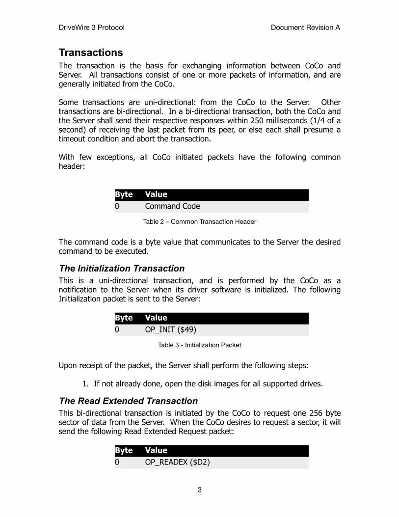
TransactionsThe transaction is the basis for exchanging information between CoCo and Server. All transactions consist of one or more packets of information, and are generally initiated from the CoCo.
Some transactions are uni-directional: from the CoCo to the Server. Other transactions are bi-directional. In a bi-directional transaction, both the CoCo and the Server shall send their respective responses within 250 milliseconds (1/4 of a second) of receiving the last packet from its peer, or else each shall presume a timeout condition and abort the transaction.
With few exceptions, all CoCo initiated packets have the following common header:
Byte Value 0 Command Code
Table 2 – Common Transaction Header
The command code is a byte value that communicates to the Server the desired command to be executed.
The Initialization TransactionThis is a uni-directional transaction, and is performed by the CoCo as a notification to the Server when its driver software is initialized. The following Initialization packet is sent to the Server:
Byte Value 0 OP_INIT ($49)
Table 3 - Initialization Packet
Upon receipt of the packet, the Server shall perform the following steps:
1. If not already done, open the disk images for all supported drives.
The Read Extended TransactionThis bi-directional transaction is initiated by the CoCo to request one 256 byte sector of data from the Server. When the CoCo desires to request a sector, it will send the following Read Extended Request packet:
Byte Value0 OP_READEX ($D2)
DriveWire 3 Protocol Document Revision A
3
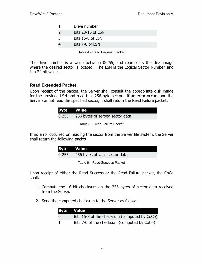
1 Drive number2 Bits 23-16 of LSN3 Bits 15-8 of LSN4 Bits 7-0 of LSN
Table 4 - Read Request Packet
The drive number is a value between 0-255, and represents the disk image where the desired sector is located. The LSN is the Logical Sector Number, and is a 24 bit value.
Read Extended PacketUpon receipt of the packet, the Server shall consult the appropriate disk image for the provided LSN and read that 256 byte sector. If an error occurs and the Server cannot read the specified sector, it shall return the Read Failure packet:
Byte Value0-255 256 bytes of zeroed sector data
Table 5 – Read Failure Packet
If no error occurred on reading the sector from the Server file system, the Server shall return the following packet:
Byte Value0-255 256 bytes of valid sector data
Table 6 – Read Success Packet
Upon receipt of either the Read Success or the Read Failure packet, the CoCo shall:
1. Compute the 16 bit checksum on the 256 bytes of sector data received from the Server.
2. Send the computed checksum to the Server as follows:
Byte Value0 Bits 15-8 of the checksum (computed by CoCo)1 Bits 7-0 of the checksum (computed by CoCo)
DriveWire 3 Protocol Document Revision A
4
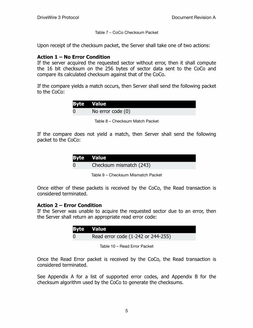
Table 7 – CoCo Checksum Packet
Upon receipt of the checksum packet, the Server shall take one of two actions:
Action 1 – No Error ConditionIf the server acquired the requested sector without error, then it shall compute the 16 bit checksum on the 256 bytes of sector data sent to the CoCo and compare its calculated checksum against that of the CoCo.
If the compare yields a match occurs, then Server shall send the following packet to the CoCo:
Byte Value0 No error code (0)
Table 8 – Checksum Match Packet
If the compare does not yield a match, then Server shall send the following packet to the CoCo:
Byte Value0 Checksum mismatch (243)
Table 9 – Checksum Mismatch Packet
Once either of these packets is received by the CoCo, the Read transaction is considered terminated.
Action 2 – Error ConditionIf the Server was unable to acquire the requested sector due to an error, then the Server shall return an appropriate read error code:
Byte Value0 Read error code (1-242 or 244-255)
Table 10 – Read Error Packet
Once the Read Error packet is received by the CoCo, the Read transaction is considered terminated.
See Appendix A for a list of supported error codes, and Appendix B for the checksum algorithm used by the CoCo to generate the checksums.
DriveWire 3 Protocol Document Revision A
5

ReRead Extended PacketIn the event that the CoCo receives a Checksum Mismatch packet during the Read Transaction, the CoCo MAY send the following packet to the Server:
Byte Value0 OP_REREADEX ($F2)1 Drive number2 Bits 23-16 of LSN3 Bits 15-8 of LSN4 Bits 7-0 of LSN
Table 11 – ReRead Extended Request Packet
Upon receiving this packet, the Server will attempt a retransmission of the requested sector.
At any time, the CoCo may suspend the re-reading of a sector if errors continue to accumulate, and the server will return to monitoring for additional commands.
The Write TransactionThis bi-directional transaction allows the CoCo to send one 256 byte sector of data to the Server in order for it to be written to a specific virtual drive.
Byte Value0 OP_WRITE ($57)1 Drive number2 Bits 23-16 of LSN3 Bits 15-8 of LSN4 Bits 7-0 of LSN5-260 256 bytes of sector data to write261 Bits 15-8 of checksum (computed by CoCo)262 Bits 7-0 of checksum (computed by CoCo)
Table 12 - Write Request Packet
The Server shall implement a timeout of 250 milliseconds (1/4 second), in the event that the CoCo stops sending data. This allows the Server to recover from the Write Transaction state and return to processing other packets.
DriveWire 3 Protocol Document Revision A
6

Once the Server receives this packet, it shall:
1. Compute the 16 bit checksum over the 256 byte sector it received
2. Compare the checksum that it computed against the checksum provided by the CoCo
Once the checksums have been compared, the Server shall acknowledge the transmission as follows:
Byte Value0 0 (checksum OK)
Table 13 – Write Success Packet
The CoCo, upon receipt of the packet, will do one the following:
1. If the error code received is 0 ($00), the CoCo will assume the transfer of the sector was a success and terminate the transmission.
2. If the error code received is 243 (E$CRC), the CoCo MAY send the following packet:
Byte Value0 OP_REWRITE ($77)1 Drive number2 Bits 23-16 of LSN3 Bits 15-8 of LSN4 Bits 7-0 of LSN5-260 256 bytes of sector data to write261 Bits 15-8 of checksum (computed by CoCo)262 Bits 7-0 of checksum (computed by CoCo)
Table 14 - ReWrite Request Packet
And the Write Transaction will commence again.
GetStat/SetStat TransactionThis uni-directional transaction is for informational purposes only and may not be supported in all client environments. Its inclusion into the protocol specification is mainly for the benefit of DriveWire-enabled OS-9 drivers that execute on the CoCo.
DriveWire 3 Protocol Document Revision A
7

In such a driver, all GetStats/SetStats are passed to the Server via the OP_GETSTAT or OP_SETSTAT code, followed by a byte representing the GetStat/SetStat code. The Server may wish to log this information, but does not act upon the packet itself.
Byte Value0 OP_GETSTAT ($47) or
OP_SETSTAT ($53)1 Drive number2 GetStat or SetStat code
Table 15 – GetStat/SetStat Packet
Termination TransactionUpon termination of the DriveWire client on the CoCo, this uni-directional transaction shall be sent to the Server:
Byte Value0 OP_TERM ($54)
Table 16 – Termination Packet
Upon receipt of the packet, the Server should:
1. Close the disk file associated for all supported drives.
The Reset TransactionWhen the CoCo’s reset button is pressed, the state of the serial port changes such that byte $FE (OP_RESET1) or $FF (OP_RESET2) will be present on the serial line. This condition is therefore considered a uni-directional transaction to the Server to indicate a global reset:
Byte Value0 OP_RESET1 ($FE) or
OP_RESET2 ($FF)
Table 17 - Reset Packet
Upon receipt of the packet, the Server shall:
1. Reset any statistical values related to read/write and sector transfer throughput for ALL drives.
2. Flush all caches connected to the virtual drives.
DriveWire 3 Protocol Document Revision A
8

No-Op TransactionThis is a uni-directional transaction that can be ignored by the Server.
Byte Value0 OP_NOP ($00)
Table 18 – No Operation Packet
Time TransactionThis bi-directional transaction allows the CoCo to request time and date information from the Server:
Byte Value0 OP_TIME ($23)
Table 19 – Time Request Packet
Upon receipt of the packet, the Server shall return the following packet to theCoCo:
Byte Value0 Current Year minus 1900 (0-255)1 Month (1-12)2 Day (0-31)3 Hour (0-23)4 Minute (0-59)5 Second (0-59)6 Day of Week (0-6; 0 = Sunday)
Table 20 – Time Delivery Packet
PRINTINGDriveWire 3 introduces a special set of transactions to allow printing to the Server that it is connected to. The Server shall maintain a printer buffer where data bytes are added until a flush command is sent. Upon receiving the flush command, the Server shall prompt the user for a printer to send the buffered data to.
DriveWire 3 Protocol Document Revision A
9
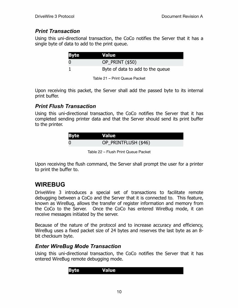
Print TransactionUsing this uni-directional transaction, the CoCo notifies the Server that it has a single byte of data to add to the print queue.
Byte Value0 OP_PRINT ($50)1 Byte of data to add to the queue
Table 21 – Print Queue Packet
Upon receiving this packet, the Server shall add the passed byte to its internal print buffer.
Print Flush TransactionUsing this uni-directional transaction, the CoCo notifies the Server that it has completed sending printer data and that the Server should send its print buffer to the printer.
Byte Value0 OP_PRINTFLUSH ($46)
Table 22 – Flush Print Queue Packet
Upon receiving the flush command, the Server shall prompt the user for a printer to print the buffer to.
WIREBUGDriveWire 3 introduces a special set of transactions to facilitate remote debugging between a CoCo and the Server that it is connected to. This feature, known as WireBug, allows the transfer of register information and memory from the CoCo to the Server. Once the CoCo has entered WireBug mode, it can receive messages initiated by the server.
Because of the nature of the protocol and to increase accuracy and efficiency, WireBug uses a fixed packet size of 24 bytes and reserves the last byte as an 8-bit checksum byte.
Enter WireBug Mode TransactionUsing this uni-directional transaction, the CoCo notifies the Server that it has entered WireBug remote debugging mode.
Byte Value
DriveWire 3 Protocol Document Revision A
10

0 OP_WIREBUG_MODE ($42)1 CoCo Type ($02 = CoCo 2, $03 =
CoCo 3)2 CPU Type ($08 = 6809, $03 = 6309)3-23 Reserved for future definition
Table 23 – Enter WireBug Mode Packet
Once the CoCo has sent this packet, it shall go into WireBug Mode where it will wait for commands from the Server.
Along with notifying the Server that the CoCo is in WireBug mode, the packet also communicates the CoCo and processor type. The Server should use this information as a cue to what type of processor is in the CoCo, and adjust accordingly.
Read Registers Transaction (Server Initiated)Using this bi-directional transaction, the Server requests the contents of the registers from the CoCo.
Byte Value0 OP_WIREBUG_READREGS ($52)1-22 023 Checksum
Table 24 – WireBug Read Registers Packet
Upon receipt of the packet, the CoCo shall compute the checksum of bytes 0-22 and compare its computed value against byte 23. If a checksum match does not occur, then the CoCo shall disregard the packet and send the following response packet:
Byte Value0 Checksum mismatch (243)
Table 25 – Checksum Mismatch Packet
Upon receipt of this packet, the Server may elect to restart the transaction.
If a match occurs, the CoCo shall respond with the following packet:
Byte Value0 OP_WIREBUG_READREGS ($52)
DriveWire 3 Protocol Document Revision A
11
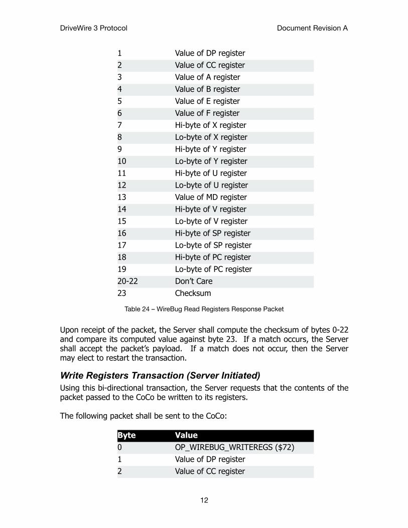
1 Value of DP register2 Value of CC register3 Value of A register4 Value of B register5 Value of E register6 Value of F register7 Hi-byte of X register8 Lo-byte of X register9 Hi-byte of Y register10 Lo-byte of Y register11 Hi-byte of U register12 Lo-byte of U register13 Value of MD register14 Hi-byte of V register15 Lo-byte of V register16 Hi-byte of SP register17 Lo-byte of SP register18 Hi-byte of PC register19 Lo-byte of PC register20-22 Don’t Care23 Checksum
Table 24 – WireBug Read Registers Response Packet
Upon receipt of the packet, the Server shall compute the checksum of bytes 0-22 and compare its computed value against byte 23. If a match occurs, the Server shall accept the packet’s payload. If a match does not occur, then the Server may elect to restart the transaction.
Write Registers Transaction (Server Initiated)Using this bi-directional transaction, the Server requests that the contents of the packet passed to the CoCo be written to its registers.
The following packet shall be sent to the CoCo:
Byte Value0 OP_WIREBUG_WRITEREGS ($72)1 Value of DP register2 Value of CC register
DriveWire 3 Protocol Document Revision A
12

3 Value of A register4 Value of B register5 Value of E register6 Value of F register7 Hi-byte of X register8 Lo-byte of X register9 Hi-byte of Y register10 Lo-byte of Y register11 Hi-byte of U register12 Lo-byte of U register13 Value of MD register14 Hi-byte of V register15 Lo-byte of V register16 Hi-byte of SP register17 Lo-byte of SP register18 Hi-byte of PC register19 Lo-byte of PC register20-22 Don’t Care23 Checksum
Table 25 – WireBug Write Registers Packet
Upon receipt of the packet, the CoCo shall compute the checksum of bytes 0-22 and compare its computed value against byte 23. If a match occurs, the CoCo shall accept the packet’s payload, update its registers and send the following response packet:
Byte Value0 No error code (0)
Table 26 – Checksum Match Packet
If a checksum match does not occur, then the CoCo shall disregard the packet and send the following response packet:
Byte Value0 Checksum mismatch (243)
DriveWire 3 Protocol Document Revision A
13

Table 27 – Checksum Mismatch Packet
Upon receipt of this packet, the Server may elect to restart the transaction.
Read Memory TransactionThis bi-directional transaction is sent from the Server to the CoCo. The Server uses this transaction to obtain memory values from the CoCo.
The following packet is sent from the Server:
Byte Value0 OP_WIREBUG_READMEM ($4D)1 Hi-byte of starting memory location2 Lo-byte of starting memory location3 Count (0 < n < 23)4-22 Don’t Care23 Checksum
Table 28 – Read Memory Request Packet
Upon receipt of the packet, the CoCo shall compute the checksum of bytes 0-22 and compare its computed value against byte 23. If a checksum match does not occur, then the CoCo shall disregard the packet and send the following response packet:
Byte Value0 Checksum mismatch (243)
Table 29 – Checksum Mismatch Packet
Upon receipt of the Checksum Mismatch Packet, the Server may elect to restart the transaction.
If a match occurs, the CoCo shall validate the memory request. If byte 3 (count) is not between 1 and 22, then the CoCo shall send the following response packet:
Byte Value0 Illegal number (16)
DriveWire 3 Protocol Document Revision A
14

Table 30 – Illegal Number Packet
If the byte count is between 1 and 22, then the CoCo shall accept the packet’s payload and send the following response packet:
Byte Value0 OP_WIREBUG_READMEM ($4D)1..n Memory from start to endn+1..22 Don’t care23 Checksum
Table 31 – Read Memory Response Packet
Upon receipt of the packet, the Server shall compute the checksum of bytes 0 to 22 and compare its computed value against byte 23. If a match occurs, the Server shall accept the packet’s payload. If a match does not occur, then the Server may elect to restart the transaction.
Write Memory TransactionThis bi-directional transaction is sent from the Server to the CoCo. The Server uses this transaction to modify the contents of the CoCo’s memory.
The following packet is sent from the Server:
Byte Value0 OP_WIREBUG_WRITEMEM ($6D)1 Hi-byte of starting memory location2 Lo-byte of starting memory location3 Count (n bytes where 0 < n < 20)4-22 Bytes to be modified23 Checksum
Table 32 – Write Memory Request Packet
Upon receipt of the packet, the CoCo shall compute the checksum of bytes 0-22 and compare its computed value against byte 23. If a checksum match does not occur, then the CoCo shall disregard the packet and send the following response packet:
Byte Value0 Checksum mismatch (243)
DriveWire 3 Protocol Document Revision A
15

Table 33 – Checksum Mismatch Packet
If a match occurs, the CoCo shall validate the memory request. If byte 3 (count) is not between 1 and 19, then the CoCo shall send the following response packet:
Byte Value0 Illegal number (16)
Table 34 – Illegal Number Packet
If the byte count is between 1 and 19, then the CoCo shall accept the packet’s payload, update its memory with the contents from the Server, and send the following response packet:
Byte Value0 No error code (0)
Table 35 – Checksum Match Packet
Continue Execution TransactionThis uni-directional transaction is sent from the Server to the CoCo. The Server uses this transaction to notify the CoCo that it should continue executing normally.
The following packet is sent from the Server:
Byte Value0 OP_WIREBUG_GO ($47)1-23 Don’t care
Table 36 – Continue Execution Packet
Upon receiving this packet, the CoCo shall exit WireBug Mode and commence execution. The Server shall commence responding to CoCo-initiated DriveWire transactions.
DriveWire 3 Protocol Document Revision A
16

Appendix A. Error CodesThe error codes used by the Server to indicate an error condition mirror the same codes used in OS-9. Here is a list of codes that should be used and the conditions that will trigger them:
• $F3 – CRC Error (if the Server’s computed checksum doesn’t match a write request from the CoCo)
• $F4 – Read Error (if the Server encounters an error when reading a sector from a virtual drive)
• $F5 – Write Error (if the Server encounters an error when writing a sector)• $F6 - Not Ready Error (if the a command requests accesses a non-
existent virtual drive)
Appendix B. DriveWire Checksum AlgorithmEven though DriveWire has been shown to provide very stable and reliable communications between CoCo and Server, a checksum algorithm has been employed to bring an added level of data integrity.
This new checksum algorithm is simpler and significantly better at tracking bit errors than the CRC algorithm employed in DriveWire Version 1, which used a fast but weak CRC method.
Designers of DriveWire Server software should implement the following checksum algorithm (presented in C source code) for computing a checksum for all sectors read and written to/from the CoCo.
int calChecksum(unsigned char *ptr, int count){
short Checksum = 0;
while(--count){
Checksum += *(ptr++);}
return (Checksum);}
Note that WireBug uses an 8-bit checksum instead of a 16 bit one.
DriveWire 3 Protocol Document Revision A
17