DRIVER INFORMATION & MULTIMEDIA WCSB A
71
WCS WCS-1 DRIVER INFORMATION & MULTIMEDIA C D E F G H I J K L M B SECTION WCS A O P CONTENTS WARNING CHIME SYSTEM BASIC INSPECTION ................................... 3 DIAGNOSIS AND REPAIR WORKFLOW ......... 3 Work Flow ................................................................ 3 FUNCTION DIAGNOSIS .............................. 5 WARNING CHIME SYSTEM .............................. 5 WARNING CHIME SYSTEM ...................................... 5 WARNING CHIME SYSTEM : System Diagram ...... 5 WARNING CHIME SYSTEM : System Description ...... 5 WARNING CHIME SYSTEM : Component Parts Location .................................................................... 6 WARNING CHIME SYSTEM : Component De- scription .................................................................... 6 LIGHT REMINDER WARNING CHIME ...................... 7 LIGHT REMINDER WARNING CHIME : System Diagram .................................................................... 7 LIGHT REMINDER WARNING CHIME : System Description ............................................................... 7 LIGHT REMINDER WARNING CHIME : Compo- nent Parts Location .................................................. 8 LIGHT REMINDER WARNING CHIME : Compo- nent Description ....................................................... 8 SEAT BELT REMINDER WARNING CHIME ............. 8 SEAT BELT REMINDER WARNING CHIME : System Diagram ....................................................... 9 SEAT BELT REMINDER WARNING CHIME : System Description .................................................. 9 SEAT BELT REMINDER WARNING CHIME : Component Parts Location ..................................... 10 SEAT BELT REMINDER WARNING CHIME : Component Description .......................................... 10 PARKING BRAKE RELEASE WARNING CHIME .... 10 PARKING BRAKE RELEASE WARNING CHIME : System Diagram ................................................... 11 PARKING BRAKE RELEASE WARNING CHIME : System Description ...............................................11 PARKING BRAKE RELEASE WARNING CHIME : Component Parts Location ...................................11 PARKING BRAKE RELEASE WARNING CHIME : Component Description ........................................12 KEY WARNING CHIME ............................................12 KEY WARNING CHIME : System Diagram ............12 KEY WARNING CHIME : System Description .......12 KEY WARNING CHIME : Component Parts Loca- tion ..........................................................................13 KEY WARNING CHIME : Component Description ....13 DIAGNOSIS SYSTEM (METER) ....................... 14 CONSULT-III Function (METER/M&A) ...................14 DIAGNOSIS SYSTEM (BCM) ........................... 17 COMMON ITEM ........................................................17 COMMON ITEM : CONSULT-III Function (BCM - COMMON ITEM) ....................................................17 BUZZER ....................................................................17 BUZZER : CONSULT-III Function (BCM - BUZZ- ER) .........................................................................18 COMPONENT DIAGNOSIS ........................ 19 POWER SUPPLY AND GROUND CIRCUIT .... 19 COMBINATION METER ...........................................19 COMBINATION METER : Diagnosis Procedure ....19 BCM (BODY CONTROL MODULE) .........................19 BCM (BODY CONTROL MODULE) : Diagnosis Procedure ...............................................................19 METER BUZZER CIRCUIT ............................... 21 Description ..............................................................21 Component Function Check ...................................21 Diagnosis Procedure ..............................................21 Revision: 2008 August 2009 Rogue
Transcript of DRIVER INFORMATION & MULTIMEDIA WCSB A
DRIVER INFORMATION & MULTIMEDIA
C
D
E
BSECTION WCS
A
WARNING CHIME SYSTEM
CS
F
G
H
I
J
K
L
M
O
P
CONTENTS
W
BASIC INSPECTION .................................... 3
DIAGNOSIS AND REPAIR WORKFLOW .......... 3Work Flow .................................................................3
FUNCTION DIAGNOSIS ............................... 5
WARNING CHIME SYSTEM ............................... 5
WARNING CHIME SYSTEM .......................................5WARNING CHIME SYSTEM : System Diagram .......5WARNING CHIME SYSTEM : System Description
......5WARNING CHIME SYSTEM : Component Parts Location .....................................................................6WARNING CHIME SYSTEM : Component De-scription .....................................................................6
LIGHT REMINDER WARNING CHIME .......................7LIGHT REMINDER WARNING CHIME : System Diagram .....................................................................7LIGHT REMINDER WARNING CHIME : System Description ................................................................7LIGHT REMINDER WARNING CHIME : Compo-nent Parts Location ...................................................8LIGHT REMINDER WARNING CHIME : Compo-nent Description ........................................................8
SEAT BELT REMINDER WARNING CHIME ..............8SEAT BELT REMINDER WARNING CHIME : System Diagram ........................................................9SEAT BELT REMINDER WARNING CHIME : System Description ...................................................9SEAT BELT REMINDER WARNING CHIME : Component Parts Location ......................................10SEAT BELT REMINDER WARNING CHIME : Component Description ...........................................10
PARKING BRAKE RELEASE WARNING CHIME ....10PARKING BRAKE RELEASE WARNING CHIME : System Diagram ....................................................11
PARKING BRAKE RELEASE WARNING CHIME : System Description ................................................11PARKING BRAKE RELEASE WARNING CHIME : Component Parts Location ....................................11PARKING BRAKE RELEASE WARNING CHIME : Component Description .........................................12
KEY WARNING CHIME .............................................12KEY WARNING CHIME : System Diagram .............12KEY WARNING CHIME : System Description ........12KEY WARNING CHIME : Component Parts Loca-tion ...........................................................................13KEY WARNING CHIME : Component Description ....13
DIAGNOSIS SYSTEM (METER) .......................14CONSULT-III Function (METER/M&A) ....................14
DIAGNOSIS SYSTEM (BCM) ...........................17
COMMON ITEM .........................................................17COMMON ITEM : CONSULT-III Function (BCM - COMMON ITEM) .....................................................17
BUZZER .....................................................................17BUZZER : CONSULT-III Function (BCM - BUZZ-ER) ..........................................................................18
COMPONENT DIAGNOSIS .........................19
POWER SUPPLY AND GROUND CIRCUIT ....19
COMBINATION METER ............................................19COMBINATION METER : Diagnosis Procedure .....19
BCM (BODY CONTROL MODULE) ..........................19BCM (BODY CONTROL MODULE) : Diagnosis Procedure ................................................................19
METER BUZZER CIRCUIT ...............................21Description ...............................................................21Component Function Check ....................................21Diagnosis Procedure ...............................................21
WCS-1Revision: 2008 August 2009 Rogue

SEAT BELT BUCKLE SWITCH SIGNAL CIR-CUIT ................................................................... 22
Description .............................................................. 22Component Function Check ................................... 22Diagnosis Procedure .............................................. 22Component Inspection ............................................ 23
PARKING BRAKE SWITCH SIGNAL CIR-CUIT ................................................................... 24
Description .............................................................. 24Diagnosis Procedure .............................................. 24Component Inspection ............................................ 24
WARNING CHIME SYSTEM ............................. 25Wiring Diagram - WARNING CHIME - .................... 25
ECU DIAGNOSIS ........................................ 29
COMBINATION METER .................................... 29Reference Value ..................................................... 29Wiring Diagram - METER - ..................................... 35Fail-safe .................................................................. 43DTC Index .............................................................. 44
BCM (BODY CONTROL MODULE) .................. 45Reference Value ..................................................... 45Wiring Diagram - BCM - ......................................... 60Fail-safe .................................................................. 64DTC Inspection Priority Chart .............................. 65DTC Index .............................................................. 65
SYMPTOM DIAGNOSIS ............................. 67
THE LIGHT REMINDER WARNING DOES NOT SOUND ...................................................... 67
Description .............................................................. 67Diagnosis Procedure ............................................... 67
THE SEAT BELT REMINDER WARNING DOES NOT SOUND .......................................... 68
Description .............................................................. 68Trouble diagnosis procedure .................................. 68
THE PARKING BRAKE RELEASE WARNING DOES NOT SOUND .......................................... 69
Description .............................................................. 69Diagnosis Procedure ............................................... 69
THE KEY WARNING DOES NOT SOUND ....... 70Description .............................................................. 70Diagnosis Procedure ............................................... 70
PRECAUTION ............................................ 71
PRECAUTIONS ................................................. 71
FOR USA AND CANADA ......................................... 71FOR USA AND CANADA : Precaution for Supple-mental Restraint System (SRS) "AIR BAG" and "SEAT BELT PRE-TENSIONER" ........................... 71
FOR MEXICO ............................................................ 71FOR MEXICO : Precaution for Supplemental Re-straint System (SRS) "AIR BAG" and "SEAT BELT PRE-TENSIONER" ................................................. 71
WCS-2Revision: 2008 August 2009 Rogue

CS
DIAGNOSIS AND REPAIR WORKFLOW
C
D
E
F
G
H
I
J
K
L
M
B
A
O
P
W
< BASIC INSPECTION >
BASIC INSPECTIONDIAGNOSIS AND REPAIR WORKFLOW
Work Flow INFOID:0000000004236539
OVERALL SEQUENCE
DETAILED FLOW
1.OBTAIN INFORMATION ABOUT SYMPTOM
Interview the customer to obtain as much information as possible about the conditions and environment underwhich the malfunction occurred.
>> GO TO 2.
2.CHECK SYMPTOM
• Check the symptom based on the information obtained from the customer.• Check if any other malfunctions are present.
>> GO TO 3.
3.CHECK CONSULT-III SELF-DIAGNOSIS RESULTS
JSNIA0456GB
WCS-3Revision: 2008 August 2009 Rogue

DIAGNOSIS AND REPAIR WORKFLOW
< BASIC INSPECTION >1. Connect CONSULT-III and perform “Self Diagnostic Result” of “METER/M&”. Refer to WCS-14, "CON-SULT-III Function (METER/M&A)".2. Check if DTC is detected. Refer to WCS-44, "DTC Index".NOTE:If “CAN COMM CIRCUIT [U1000]” is displayed, start with the diagnosis for the CAN communication system.Refer to MWI-36, "Diagnosis Procedure".If any DTC detected?YES >> GO TO 5.NO >> GO TO 4.
4.NARROW DOWN THE MALFUNCTIONING PARTS BY SYMPTOM DIAGNOSIS
Perform symptom diagnosis and narrow down the malfunctioning parts.
>> GO TO 5.
5.REPAIR OR REPLACE MALFUNCTIONING PARTS
Repair or replace malfunctioning parts.NOTE:If DTC is displayed, erase DTC after repair or replace malfunctioning parts.
>> GO TO 6.
6.FINAL CHECK
Check that the warning buzzer in the combination meter operates normally.Does it operate normally?YES >> INSPECTION ENDNO >> GO TO 1.
WCS-4Revision: 2008 August 2009 Rogue

CS
WARNING CHIME SYSTEM
C
D
E
F
G
H
I
J
K
L
M
B
A
O
P
W
< FUNCTION DIAGNOSIS >
FUNCTION DIAGNOSISWARNING CHIME SYSTEMWARNING CHIME SYSTEM
WARNING CHIME SYSTEM : System Diagram INFOID:0000000004236540
WARNING CHIME SYSTEM : System Description INFOID:0000000004236541
The buzzer (1) for the warning chime system is integrated in thecombination meter. Combination meter sounds warning buzzer inthe following conditions.• When receiving the buzzer output signal (light reminder warning
chime, key warning chime, seat belt reminder warning chime) fromBCM.
• When it judges the necessity of buzzer output according to vehiclespeed signal received from ABS actuator and electric unit (controlunit) with CAN communication and parking brake switch signalreceived from parking brake switch.
• When receiving the buzzer output signal (Intelligent Key warningchime) from Intelligent Key unit. For the further details, refer toDLK-34, "WARNING FUNCTION : System Description".
WARNING CHIME FUNCTION LIST
JSNIA0663GB
JSNIA0319ZZ
Warning functions Signal name Warning chime judge unit
Light reminder warning chime• Ignition switch signal• Lighting switch position signal• Front door switch signal (driver side)
BCMKey warning chime
• Ignition switch signal• Key switch signal• Front door switch signal (driver side)
Seat belt reminder warning chime• Seat belt buckle switch (driver side) signal• Ignition switch signal
WCS-5Revision: 2008 August 2009 Rogue
WARNING CHIME SYSTEM
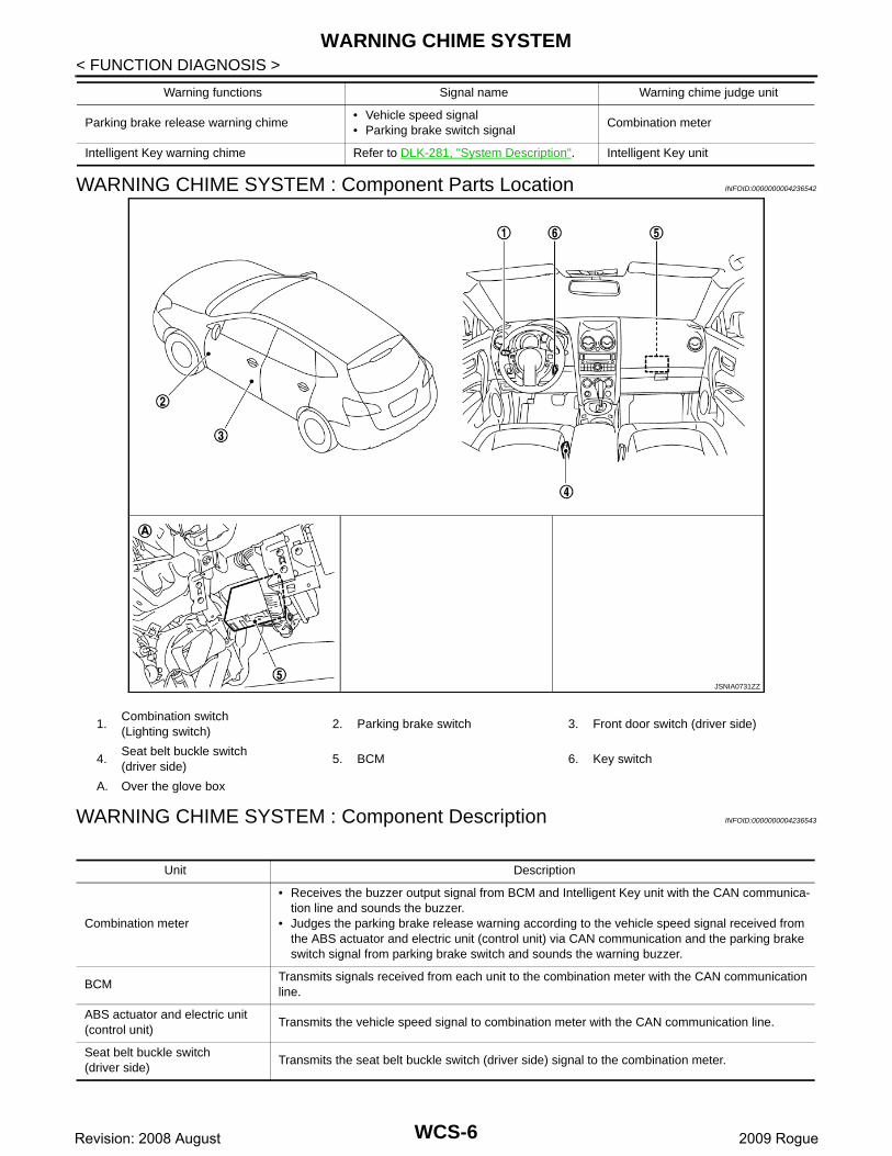
< FUNCTION DIAGNOSIS >WARNING CHIME SYSTEM : Component Parts Location INFOID:0000000004236542
WARNING CHIME SYSTEM : Component Description INFOID:0000000004236543
Parking brake release warning chime• Vehicle speed signal• Parking brake switch signal
Combination meter
Intelligent Key warning chime Refer to DLK-281, "System Description". Intelligent Key unit
Warning functions Signal name Warning chime judge unit
JSNIA0731ZZ
1.Combination switch(Lighting switch)
2. Parking brake switch 3. Front door switch (driver side)
4.Seat belt buckle switch(driver side)
5. BCM 6. Key switch
A. Over the glove box
Unit Description
Combination meter
• Receives the buzzer output signal from BCM and Intelligent Key unit with the CAN communica-tion line and sounds the buzzer.
• Judges the parking brake release warning according to the vehicle speed signal received from the ABS actuator and electric unit (control unit) via CAN communication and the parking brake switch signal from parking brake switch and sounds the warning buzzer.
BCMTransmits signals received from each unit to the combination meter with the CAN communication line.
ABS actuator and electric unit (control unit)
Transmits the vehicle speed signal to combination meter with the CAN communication line.
Seat belt buckle switch(driver side)
Transmits the seat belt buckle switch (driver side) signal to the combination meter.
WCS-6Revision: 2008 August 2009 Rogue
CS
WARNING CHIME SYSTEM
C
D
E
F
G
H
I
J
K
L
M
B
A
O
P
W
< FUNCTION DIAGNOSIS >
LIGHT REMINDER WARNING CHIME
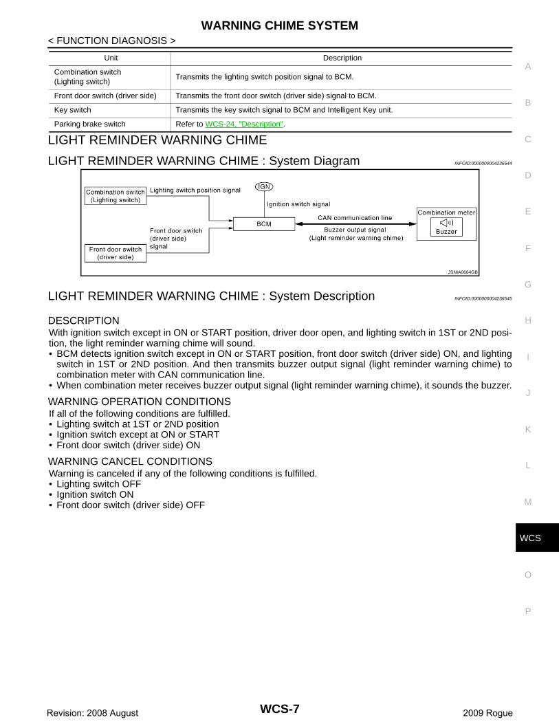
LIGHT REMINDER WARNING CHIME : System Diagram INFOID:0000000004236544
LIGHT REMINDER WARNING CHIME : System Description INFOID:0000000004236545
DESCRIPTIONWith ignition switch except in ON or START position, driver door open, and lighting switch in 1ST or 2ND posi-tion, the light reminder warning chime will sound.• BCM detects ignition switch except in ON or START position, front door switch (driver side) ON, and lighting
switch in 1ST or 2ND position. And then transmits buzzer output signal (light reminder warning chime) tocombination meter with CAN communication line.
• When combination meter receives buzzer output signal (light reminder warning chime), it sounds the buzzer.
WARNING OPERATION CONDITIONSIf all of the following conditions are fulfilled.• Lighting switch at 1ST or 2ND position• Ignition switch except at ON or START• Front door switch (driver side) ON
WARNING CANCEL CONDITIONSWarning is canceled if any of the following conditions is fulfilled.• Lighting switch OFF • Ignition switch ON• Front door switch (driver side) OFF
Combination switch (Lighting switch)
Transmits the lighting switch position signal to BCM.
Front door switch (driver side) Transmits the front door switch (driver side) signal to BCM.
Key switch Transmits the key switch signal to BCM and Intelligent Key unit.
Parking brake switch Refer to WCS-24, "Description".
Unit Description
JSNIA0664GB
WCS-7Revision: 2008 August 2009 Rogue

WARNING CHIME SYSTEM
< FUNCTION DIAGNOSIS >LIGHT REMINDER WARNING CHIME : Component Parts Location INFOID:0000000004236546
LIGHT REMINDER WARNING CHIME : Component Description INFOID:0000000004236547
SEAT BELT REMINDER WARNING CHIME
JSNIA0731ZZ
1.Combination switch(Lighting switch)
2. Parking brake switch 3. Front door switch (driver side)
4.Seat belt buckle switch(driver side)
5. BCM 6. Key switch
A. Over the glove box
Unit Description
Combination meter Receives a buzzer output signal from the BCM and sounds the buzzer.
BCMJudges light reminder warning according to the front door switch (driver side) signal from the front door switch (driver side) and the lighting position signal from the combination switch (lighting switch) and transmits the buzzer output signal to the combination meter via CAN communication.
Combination switch(Lighting switch)
Transmits the lighting switch position signal to BCM.
Front door switch (driver side) Transmits the front door switch (driver side) signal to BCM.
WCS-8Revision: 2008 August 2009 Rogue

CS
WARNING CHIME SYSTEM
C
D
E
F
G
H
I
J
K
L
M
B
A
O
P
W
< FUNCTION DIAGNOSIS >
SEAT BELT REMINDER WARNING CHIME : System Diagram INFOID:0000000004236548
SEAT BELT REMINDER WARNING CHIME : System Description INFOID:0000000004236549
DESCRIPTIONWith ignition switch turned ON and driver seat belt unfastened, seat belt warning chime will sound for approxi-mately 6 seconds.• BCM receives seat belt buckle switch signal from combination meter with CAN communication line.• BCM detects ignition switch turned ON and seat belt buckle switch (driver side) ON. And then transmits
buzzer output signal (seat belt warning chime) to combination meter with CAN communication line.• When combination meter receives buzzer output signal (seat belt warning chime), it sounds the buzzer.
WARNING OPERATION CONDITIONSIf all of the following conditions are fulfilled.• Ignition switch OFF→ON• Seat belt buckle switch (driver side) is ON (driver seat belt not fastened)
WARNING CANCEL CONDITIONSWarning is canceled if any of the following conditions is fulfilled.• Ignition switch OFF• Seat belt buckle switch (driver side) is OFF (driver seat belt fastened)
JSNIA0665GB
WCS-9Revision: 2008 August 2009 Rogue

WARNING CHIME SYSTEM
< FUNCTION DIAGNOSIS >SEAT BELT REMINDER WARNING CHIME : Component Parts Location INFOID:0000000004236550
SEAT BELT REMINDER WARNING CHIME : Component Description INFOID:0000000004236551
PARKING BRAKE RELEASE WARNING CHIME
JSNIA0731ZZ
1.Combination switch(Lighting switch)
2. Parking brake switch 3. Front door switch (driver side)
4.Seat belt buckle switch(driver side)
5. BCM 6. Key switch
A. Over the glove box
Unit Description
Combination meter Receives a buzzer output signal from the BCM and sounds the buzzer.
BCMJudges the seat belt warning condition from the seat belt buckle switch (driver side) signal received from the combination meter and transmits a buzzer output signal to the combination meter via CAN communication line if necessary.
Seat belt buckle switch(driver side)
Refer to WCS-22, "Description".
WCS-10Revision: 2008 August 2009 Rogue

CS
WARNING CHIME SYSTEM
C
D
E
F
G
H
I
J
K
L
M
B
A
O
P
W
< FUNCTION DIAGNOSIS >
PARKING BRAKE RELEASE WARNING CHIME : System Diagram INFOID:0000000004236552
PARKING BRAKE RELEASE WARNING CHIME : System Description INFOID:0000000004236553
DESCRIPTIONParking brake release warning chime judges the remaining parking brake according to the vehicle speed sig-nal received from the ABS actuator and electric unit (control unit) via CAN communication and the parkingbrake switch signal from parking brake switch to sound the warning buzzer.
WARNING OPERATION CONDITIONSIF all of the following conditions are fulfilled.• Vehicle speed is 7 km/h (4.3 MPH) or more• Parking brake switch ON
WARNING CANCEL CONDITIONSWarning is canceled if any of the following conditions is fulfilled.• Vehicle speed is approximately 3 km/h (1.9 MPH) or less• Parking brake switch OFF
PARKING BRAKE RELEASE WARNING CHIME : Component Parts LocationINFOID:0000000004236554
JSNIA0666GB
JSNIA0731ZZ
WCS-11Revision: 2008 August 2009 Rogue

WARNING CHIME SYSTEM
< FUNCTION DIAGNOSIS >PARKING BRAKE RELEASE WARNING CHIME : Component Description INFOID:0000000004236555
KEY WARNING CHIME
KEY WARNING CHIME : System Diagram INFOID:0000000004236556
KEY WARNING CHIME : System Description INFOID:0000000004236557
DESCRIPTIONWith the key inserted into the ignition key cylinder, and the ignition switch except in ON or START position,when driver door open, the key warning chime will sound.• BCM detects key inserted into the ignition key cylinder, ignition switch except in ON or START position, front
door switch (driver side) ON. And then transmits buzzer output signal (Key warning chime) to combinationmeter with CAN communication line.
• When combination meter receives buzzer output signal (Key warning chime), it sounds the buzzer.NOTE:With Intelligent Key system: refer to DLK-32, "KEY REMINDER FUNCTION : System Description".
WARNING OPERATION CONDITIONSIf all of the following conditions are fulfilled.• Key inserted into the ignition key cylinder (Key switch signal ON)• Ignition switch except in ON or START (Ignition switch signal OFF)• Front door switch (driver side) open [Front door switch (driver side) signal ON]
WARNING CANCEL CONDITIONSWarning is canceled if any of the following conditions is fulfilled.• Key removed from key cylinder (Key switch signal OFF)• Ignition switch in ON or START (Ignition switch signal ON)• Front door switch (driver side) close [Front door switch (driver side) signal OFF]
1.Combination switch(Lighting switch)
2. Parking brake switch 3. Front door switch (driver side)
4.Seat belt buckle switch(driver side)
5. BCM 6. Key switch
A. Over the glove box
Unit Description
Combination meterJudges the remaining parking brake according to the vehicle speed signal received from the ABS actuator and electric unit (control unit) via CAN communication and the parking brake switch signal from parking brake switch and sounds the warning buzzer.
ABS actuator and electric unit (control unit)
Transmits the vehicle speed signal to the combination meter via CAN communication.
Parking brake switch Refer to WCS-24, "Description".
JSNIA0667GB
WCS-12Revision: 2008 August 2009 Rogue

CS
WARNING CHIME SYSTEM
C
D
E
F
G
H
I
J
K
L
M
B
A
O
P
W
< FUNCTION DIAGNOSIS >
KEY WARNING CHIME : Component Parts Location INFOID:0000000004236558
KEY WARNING CHIME : Component Description INFOID:0000000004236559
JSNIA0731ZZ
1.Combination switch(Lighting switch)
2. Parking brake switch 3. Front door switch (driver side)
4.Seat belt buckle switch(driver side)
5. BCM 6. Key switch
A. Over the glove box
Unit Description
Combination meter Received a buzzer output signal from the BCM and sounds the buzzer.
BCMJudges key warning according to the door switch signal from the front door switch (driver side) and the key switch signal from the key switch and transmits the buzzer output signal to the combination meter via CAN communication.
Front door switch (driver side) Transmits the door switch signal to BCM.
Key switch Transmits the key switch signal to BCM and Intelligent Key unit.
WCS-13Revision: 2008 August 2009 Rogue

DIAGNOSIS SYSTEM (METER)
< FUNCTION DIAGNOSIS >DIAGNOSIS SYSTEM (METER)
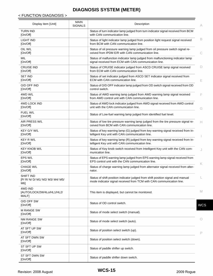
CONSULT-III Function (METER/M&A) INFOID:0000000004512078
CONSULT-III FUNCTION (METER/M&A)
SELF DIAGNOSTIC RESULTRefer to MWI-68, "DTC Index".
DATA MONITOR
Display Item ListX: Applicable
System Diagnosis mode Description
METER/M&ASelf Diagnostic Result Combination meter checks the conditions and displays memorized error.
Data Monitor Displays combination meter input/output data in real time.
Display item [Unit]MAIN
SIGNALSDescription
SPEED METER[km/h]
X
Value of vehicle speed signal received from ABS actuator and electric unit (con-trol unit) with CAN communication line.NOTE:655.35 is displayed when the malfunction signal is received.
SPEED OUTPUT[km/h]
X
Vehicle speed signal value transmitted to other units with CAN communication line.NOTE:655.35 is displayed when the malfunction signal is received.
ODO OUTPUT[km/h or mph]
Odometer signal value transmitted to other units with CAN communication line.
TACHO METER[rpm]
X
Value of the engine speed signal received from ECM with CAN communication line.NOTE:8191.875 is displayed when the malfunction signal is received.
FUEL METER[lit.]
X Fuel level indicated on combination meter.
W TEMP METER[°C]
X
Value of engine coolant temperature signal received from ECM with CAN com-munication line. NOTE:215 is displayed when the malfunction signal is input.
INST FUEL[km/L]
This item is displayed, but cannot be monitored.
ABS W/L[On/Off]
Status of ABS warning lamp judged from ABS warning lamp signal received from ABS actuator and electric unit (control unit) with CAN communication line.
VDC/TCS IND[On/Off]
Status of VDC OFF indicator lamp judged from VDC OFF indicator lamp signal received from ABS actuator and electric unit (control unit) with CAN communica-tion line.
SLIP IND[On/Off]
Status of slip indicator lamp judged from slip indicator lamp signal received from ABS actuator and electric unit (control unit) with CAN communication line.
BRAKE W/L[On/Off]
Status of brake warning lamp judged from brake warning lamp signal received from ABS actuator and electric unit (control unit) with CAN communication line.NOTE:Displays “Off” if the brake warning lamp is illuminated when the valve check starts, the parking brake switch is turned ON or the brake fluid level switch is turned ON.
DOOR W/L[On/Off]
Status of door warning lamp judged from door switch signal received from BCM with CAN communication line.
HI -BEAM IND[On/Off]
Status of high beam indicator lamp judged from high beam request signal re-ceived from BCM with CAN communication line.
WCS-14Revision: 2008 August 2009 Rogue
CS
DIAGNOSIS SYSTEM (METER)
C
D
E
F
G
H
I
J
K
L
M
B
A
O
P
W
< FUNCTION DIAGNOSIS >
TURN IND[On/Off]
Status of turn indicator lamp judged from turn indicator signal received from BCM with CAN communication line.
LIGHT IND[On/Off]
Status of light indicator lamp judged from position light request signal received from BCM with CAN communication line.
OIL W/L[On/Off]
Status of oil pressure warning lamp judged from oil pressure switch signal re-ceived from IPDM E/R with CAN communication line.
MIL[On/Off]
Status of malfunction indicator lamp judged from malfunctioning indicator lamp signal received from ECM with CAN communication line.
CRUISE IND[On/Off]
Status of CRUISE indicator judged from ASCD CRUISE lamp signal received from ECM with CAN communication line.
SET IND[On/Off]
Status of set indicator judged from ASCD SET indicator signal received from ECM with CAN communication line.
O/D OFF IND[On/Off]
Status of O/D OFF indicator lamp judged from OD switch signal received from OD control switch.
4WD W/L[On/Off]
Status of AWD warning lamp judged from AWD warning lamp signal received from AWD control unit with CAN communication line.
4WD LOCK IND[On/Off]
Status of AWD lock indicator judged from AWD signal received from AWD control unit with the CAN communication line.
FUEL W/L[On/Off]
Status of Low-fuel warning lamp judged from identified fuel level.
AIR PRESS W/L[On/Off]
Status of low tire pressure warning lamp judged from the tire pressure signal re-ceived from BCM with CAN communication line.
KEY G/Y W/L[On/Off]
Status of key warning lamp (G) judged from key warning signal received from In-telligent Key unit with CAN communication line.
KEY R W/L[On/Off]
Status of key warning lamp (R) judged from key warning signal received from In-telligent Key unit with CAN communication line.
KEY KNOB W/L[On/Off]
Status of Key knob switch received from Intelligent Key unit with the CAN com-munication line.
EPS W/L[On/Off]
Status of EPS warning lamp judged from EPS warning lamp signal received from EPS control unit with the CAN communication line.
CHAGE W/L[On/Off]
Status of charge warning lamp judged from alternator signal received from alter-nator.
SHIFT IND[P/ R/ N/ D/ M1/ M2/ M3/ M4/ M5/ M6]
Status of shift position indicator judged from shift position signal and manual mode indicator signal received from TCM with CAN communication line.
4WD IND[AUTO/LOCK/2W/4Lo/HL1/HL2/MALF]
This item is displayed, but cannot be monitored.
O/D OFF SW[On/Off]
Status of OD control switch.
M RANGE SW[On/Off]
Status of mode select switch (manual).
NM RANGE SW[On/Off]
Status of mode select switch (auto).
AT SFT UP SW[On/Off]
Status of position select switch (up).
AT SFT DWN SW[On/Off]
Status of position select switch (down).
ST SFT UP SW[On/Off]
Status of paddle shifter up switch.
ST SFT DWN SW[On/Off]
Status of paddle shifter down switch.
Display item [Unit]MAIN
SIGNALSDescription
WCS-15Revision: 2008 August 2009 Rogue
DIAGNOSIS SYSTEM (METER)
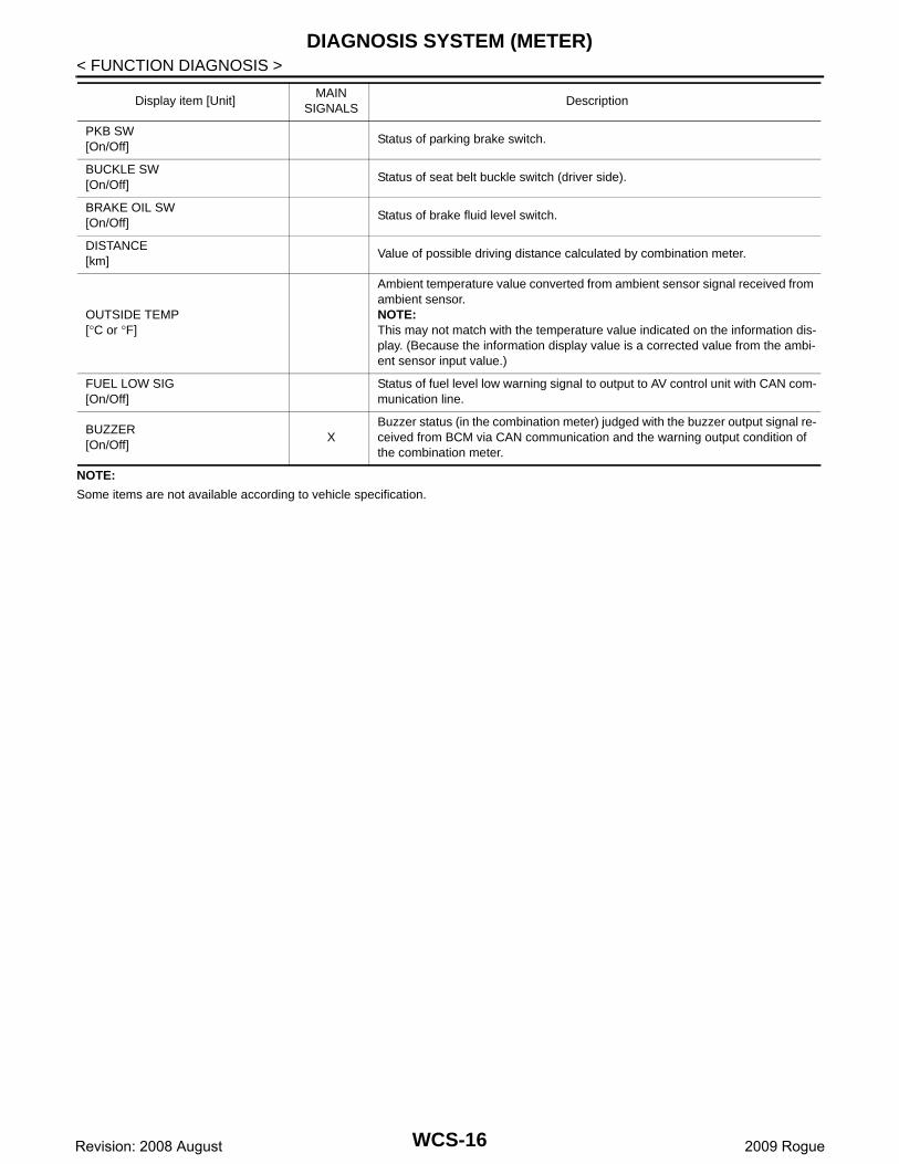
< FUNCTION DIAGNOSIS >NOTE:
Some items are not available according to vehicle specification.
PKB SW[On/Off]
Status of parking brake switch.
BUCKLE SW[On/Off]
Status of seat belt buckle switch (driver side).
BRAKE OIL SW[On/Off]
Status of brake fluid level switch.
DISTANCE[km]
Value of possible driving distance calculated by combination meter.
OUTSIDE TEMP[°C or °F]
Ambient temperature value converted from ambient sensor signal received from ambient sensor.NOTE:This may not match with the temperature value indicated on the information dis-play. (Because the information display value is a corrected value from the ambi-ent sensor input value.)
FUEL LOW SIG[On/Off]
Status of fuel level low warning signal to output to AV control unit with CAN com-munication line.
BUZZER[On/Off]
XBuzzer status (in the combination meter) judged with the buzzer output signal re-ceived from BCM via CAN communication and the warning output condition of the combination meter.
Display item [Unit]MAIN
SIGNALSDescription
WCS-16Revision: 2008 August 2009 Rogue
CS
DIAGNOSIS SYSTEM (BCM)
C
D
E
F
G
H
I
J
K
L
M
B
A
O
P
W
< FUNCTION DIAGNOSIS >
DIAGNOSIS SYSTEM (BCM)COMMON ITEM
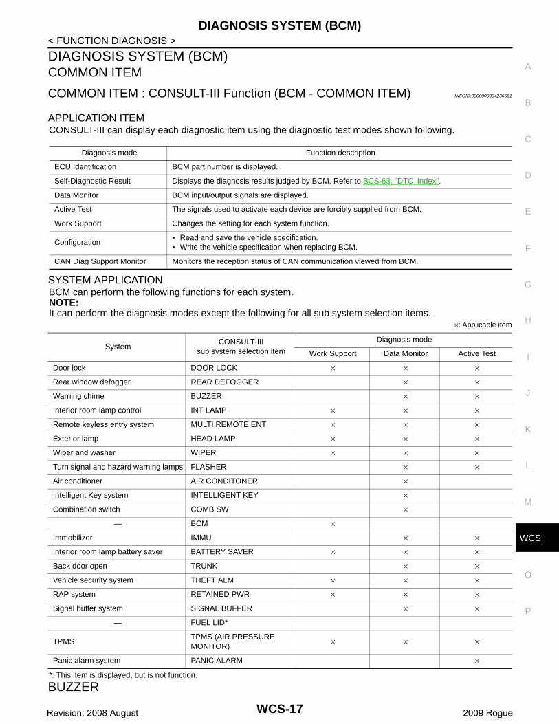
COMMON ITEM : CONSULT-III Function (BCM - COMMON ITEM) INFOID:0000000004236561
APPLICATION ITEMCONSULT-III can display each diagnostic item using the diagnostic test modes shown following.
SYSTEM APPLICATIONBCM can perform the following functions for each system.NOTE:It can perform the diagnosis modes except the following for all sub system selection items.
×: Applicable item
*: This item is displayed, but is not function.
BUZZER
Diagnosis mode Function description
ECU Identification BCM part number is displayed.
Self-Diagnostic Result Displays the diagnosis results judged by BCM. Refer to BCS-63, "DTC Index".
Data Monitor BCM input/output signals are displayed.
Active Test The signals used to activate each device are forcibly supplied from BCM.
Work Support Changes the setting for each system function.
Configuration• Read and save the vehicle specification.• Write the vehicle specification when replacing BCM.
CAN Diag Support Monitor Monitors the reception status of CAN communication viewed from BCM.
SystemCONSULT-III
sub system selection item
Diagnosis mode
Work Support Data Monitor Active Test
Door lock DOOR LOCK × × ×
Rear window defogger REAR DEFOGGER × ×
Warning chime BUZZER × ×
Interior room lamp control INT LAMP × × ×
Remote keyless entry system MULTI REMOTE ENT × × ×
Exterior lamp HEAD LAMP × × ×
Wiper and washer WIPER × × ×
Turn signal and hazard warning lamps FLASHER × ×
Air conditioner AIR CONDITONER ×
Intelligent Key system INTELLIGENT KEY ×
Combination switch COMB SW ×
— BCM ×
Immobilizer IMMU × ×
Interior room lamp battery saver BATTERY SAVER × × ×
Back door open TRUNK × ×
Vehicle security system THEFT ALM × × ×
RAP system RETAINED PWR × × ×
Signal buffer system SIGNAL BUFFER × ×
— FUEL LID*
TPMSTPMS (AIR PRESSURE MONITOR)
× × ×
Panic alarm system PANIC ALARM ×
WCS-17Revision: 2008 August 2009 Rogue

DIAGNOSIS SYSTEM (BCM)
< FUNCTION DIAGNOSIS >BUZZER : CONSULT-III Function (BCM - BUZZER) INFOID:0000000004236562
CONSULT-III FUNCTION (BCM – BUZZER)
DATA MONITOR
ACTIVE TEST
Test item Diagnosis mode Description
BuzzerData Monitor Displays BCM input data in real time.
Active Test Operation of electrical loads can be checked by sending driving signal to them.
Display item[Unit]
Description
IGN ON SW[On/Off]
Ignition switch (ON) status judged by ignition power supply input.
KEY ON SW[On/Off]
Key switch status.
DOOR SW -DR[On/Off]
Front door switch (driver side) status judged by BCM.
LIGHT SW 1ST[On/Off]
Lighting switch status judged by the lighting switch signal read with combination switch reading func-tion.
BUCKLE SW[On/Off]
Seat belt buckle switch (driver side) status judged by BCM.
Display item Description
LIGHT WARN ALMThe light reminder warning chime operation can be checked by operating the relevant function (On/Off).
IGN KEY WARN ALM The key warning chime operation can be checked by operating the relevant function (On/Off).
SEAT BELT WARN TESTThe seat belt reminder warning chime operation can be checked by operating the relevant function (On/Off).The seat belt warning chime operation can be checked by operating the relevant function (On/Off).
WCS-18Revision: 2008 August 2009 Rogue

CS
POWER SUPPLY AND GROUND CIRCUIT
C
D
E
F
G
H
I
J
K
L
M
B
A
O
P
W
< COMPONENT DIAGNOSIS >
COMPONENT DIAGNOSISPOWER SUPPLY AND GROUND CIRCUITCOMBINATION METER
COMBINATION METER : Diagnosis Procedure INFOID:0000000004535323
1.CHECK FUSE
Check for blown fuses.
Is the inspection result normal?YES >> GO TO 2.NO >> Be sure to eliminate cause of malfunction before installing new fuse.
2.CHECK POWER SUPPLY CIRCUIT
Check voltage between combination meter harness connector terminal and ground.
Is the inspection result normal?YES >> GO TO 3.NO >> Check harness between combination meter and fuse.
3.CHECK GROUND CIRCUIT
1. Turn ignition switch OFF.2. Disconnect combination meter connector.3. Check continuity between combination meter harness connector terminal and ground.
Is the inspection result normal?YES >> INSPECTION ENDNO >> Repair harness or connector.
BCM (BODY CONTROL MODULE)
BCM (BODY CONTROL MODULE) : Diagnosis Procedure INFOID:0000000004553943
1.CHECK FUSES AND FUSIBLE LINK
Check that the following fuses and fusible link are not fusing.
Signal name Fuses No.
Battery power supply 9
Ignition signal 3
TerminalsIgnition switch position
(+)
(−)Combination meterOFF ON
Connector Terminal
M34
1
Ground
Batteryvoltage
Batteryvoltage
2Approx.
0 VBatteryvoltage
Combination meter
Ground
ContinuityConnector Terminal
M343
Existed23
WCS-19Revision: 2008 August 2009 Rogue

POWER SUPPLY AND GROUND CIRCUIT
< COMPONENT DIAGNOSIS >Is the fuse fusing?YES >> Replace the blown fuse or fusible link after repairing the affected circuit if a fuse or fusible link is
blown.NO >> GO TO 2.
2.CHECK POWER SUPPLY CIRCUIT
1. Turn the ignition switch OFF.2. Disconnect BCM connectors.3. Check voltage between BCM harness connector and the ground.
Is the measurement value normal?YES >> GO TO 3.NO >> Repair the harness or connector.
3.CHECK GROUND CIRCUIT
Check continuity between BCM harness connector and the ground.
Does continuity exist?YES >> INSPECTION ENDNO >> Repair the harness or connector.
Signal name Fuses and fusible link No.
Battery power supply10
J
ACC power supply 20
Ignition power supply 1
TerminalsIgnition switch position
(+)
(−)BCMOFF ACC ON
Connector Terminal
M6770
Ground
Battery voltage
Battery voltage
Battery voltage57
M65
11Approx.
0 VBattery voltage
Battery voltage
38Approx.
0 VApprox.
0 VBattery voltage
BCM
GroundContinuity
Connector Terminal
M67 67 Existed
WCS-20Revision: 2008 August 2009 Rogue

CS
METER BUZZER CIRCUIT
C
D
E
F
G
H
I
J
K
L
M
B
A
O
P
W
< COMPONENT DIAGNOSIS >
METER BUZZER CIRCUIT
Description INFOID:0000000004236565
• The buzzer for warning chime system is installed in the combination meter.• The combination meter sounds the alarm buzzer based on the signals transmitted from various units.
Component Function Check INFOID:0000000004236566
1.CHECK OPERATION OF METER BUZZER
1. Connect the CONSULT-III2. Perform “LIGHT WARN ALM”, “IGN KEY WARN ALM” or “SEAT BELT WARN TEST” in “ACTIVE TEST”
of “BCM (BUZZER)”.Does meter buzzer beep?YES >> INSPECTION ENDNO >> GO TO 2.
2.CHECK COMBINATION METER INPUT SIGNAL
Select the “Data Monitor” of “METER/M&A” and check the “BUZZER” monitor value.
Is the inspection result normal?YES >> Replace combination meter. Refer to MWI-86, "Removal and Installation".NO >> Replace BCM. Refer to BCS-67, "Exploded View".
Diagnosis Procedure INFOID:0000000004236567
1.CHECK POWER SUPPLY AND GROUND CIRCUIT OF COMBINATION METER
Check power supply and ground circuit of combination meter. Refer to MWI-41, "COMBINATION METER :Diagnosis Procedure".Is the inspection result normal?YES >> INSPECTION ENDNO >> Repair or replace malfunctioning parts.
“BUZZER”
Under the condition of buzzer input : On
Except above : Off
WCS-21Revision: 2008 August 2009 Rogue

SEAT BELT BUCKLE SWITCH SIGNAL CIRCUIT
< COMPONENT DIAGNOSIS >SEAT BELT BUCKLE SWITCH SIGNAL CIRCUIT
Description INFOID:0000000004236568
Transmits a seat belt buckle switch signal to the combination meter.
Component Function Check INFOID:0000000004236569
1.CHECK COMBINATION METER INPUT SIGNAL
1. Connect the CONSULT-III2. Select the “Data Monitor” of “METER/M&A” and check the “BUCKLE SW” monitor value.
>> INSPECTION END
Diagnosis Procedure INFOID:0000000004236570
1.CHECK COMBINATION METER INPUT SIGNAL
1. Turn ignition switch ON. 2. Check voltage between combination meter harness connector terminal and ground.
Is the inspection result normal? YES >> INSPECTION ENDNO >> GO TO 2.
2.CHECK SEAT BELT BUCKLE SWITCH (DRIVER SIDE) SIGNAL CIRCUIT
1. Turn ignition switch OFF.2. Disconnect combination meter connector and seat belt buckle switch (driver side) connector.3. Check continuity between combination meter harness connector terminal and front seat belt buckle switch
(driver side) harness connector terminal.
4. Check harness continuity between combination meter harness connector terminal and ground.
Is the inspection result normal? YES >> GO TO 3.NO >> Repair harness or connector.
3.CHECK SEAT BELT BUCKLE SWITCH (DRIVER SIDE) GROUND CIRCUIT
“BUCKLE SW”
When driver seat belt is fastened : Off
When driver seat belt is unfastened : On
Terminal
ConditionVoltage
(Approx.)
(+)
(–)Combination meter
Connector Terminal
M34 35 GroundWhen driver seat belt is fastened 12 V
When driver seat belt is unfastened 0 V
Combination meter Seat belt buckle switch (driver side)Continuity
Connector Terminal Connector Terminal
M34 35 B409 1 Existed
Combination meter
GroundContinuity
Connector Terminal
M34 35 Not existed
WCS-22Revision: 2008 August 2009 Rogue

CS
SEAT BELT BUCKLE SWITCH SIGNAL CIRCUIT
C
D
E
F
G
H
I
J
K
L
M
B
A
O
P
W
< COMPONENT DIAGNOSIS >Check harness continuity between seat belt buckle switch (driver side) harness connector terminal andground.
Is the inspection result normal?YES >> INSPECTION ENDNO >> Repair harness or connector.
Component Inspection INFOID:0000000004236571
1.CHECK SEAT BELT BUCKLE SWITCH UNIT
1. Turn ignition switch OFF.2. Disconnect the seat belt buckle switch connector.3. Check continuity between terminals 1 and 2.
Is the inspection result normal?YES >> INSPECTION ENDNO >> Replace the seat belt buckle. Refer to SB-8, "SEAT BELT BUCKLE : Removal and Installation".
Seat belt buckle switch (driver side)
GroundContinuity
Connector Terminal
B409 2 Existed
Terminals Condition Continuity
1 2When driver seat belt is fastened Not existed
When driver seat belt is unfastened Existed
WCS-23Revision: 2008 August 2009 Rogue

PARKING BRAKE SWITCH SIGNAL CIRCUIT
< COMPONENT DIAGNOSIS >PARKING BRAKE SWITCH SIGNAL CIRCUIT
Description INFOID:0000000004236572
Transmits the parking brake switch signal to the combination meter.
Diagnosis Procedure INFOID:0000000004236573
1.CHECK COMBINATION METER INPUT SIGNAL
1. Turn ignition switch ON.2. Check voltage between combination meter harness connector terminal and ground.
Is the inspection result normal?YES >> INSPECTION ENDNO >> GO TO 2.
2.CHECK PARKING BRAKE SWITCH SIGNAL CIRCUIT
1. Turn ignition switch OFF. 2. Disconnect combination meter connector and parking brake switch connector.3. Check continuity between combination meter harness connector terminal and parking brake switch har-
ness connector terminal.
4. Check continuity between combination meter harness connector terminal and ground.
Is the inspection result normal? YES >> INSPECTION ENDNO >> Repair harness or connector.
Component Inspection INFOID:0000000004236574
Refer to BRC-45, "Component Inspection".
Terminal
ConditionVoltage
(Approx.)
(+)
(–)Combination meter
Connector Terminal
M34 26 GroundParking brake ON 0 V
Parking brake OFF 5 V
Combination meter Parking brake switchContinuity
Connector Terminal Connector Terminal
M34 26 E103 1 Existed
Combination meter
GroundContinuity
Connector Terminal
M34 26 Not existed
WCS-24Revision: 2008 August 2009 Rogue

CS
WARNING CHIME SYSTEM
C
D
E
F
G
H
I
J
K
L
M
B
A
O
P
W
< COMPONENT DIAGNOSIS >
WARNING CHIME SYSTEM
Wiring Diagram - WARNING CHIME - INFOID:0000000004236575
JCNWM1633GB
WCS-25Revision: 2008 August 2009 Rogue

WARNING CHIME SYSTEM
< COMPONENT DIAGNOSIS >JCNWM1634GB
WCS-26Revision: 2008 August 2009 Rogue

CS
WARNING CHIME SYSTEM
C
D
E
F
G
H
I
J
K
L
M
B
A
O
P
W
< COMPONENT DIAGNOSIS >
JCNWM1635GB
WCS-27Revision: 2008 August 2009 Rogue

WARNING CHIME SYSTEM
< COMPONENT DIAGNOSIS >JCNWM1636GB
WCS-28Revision: 2008 August 2009 Rogue

CS
COMBINATION METER
C
D
E
F
G
H
I
J
K
L
M
B
A
O
P
W
< ECU DIAGNOSIS >
ECU DIAGNOSISCOMBINATION METER
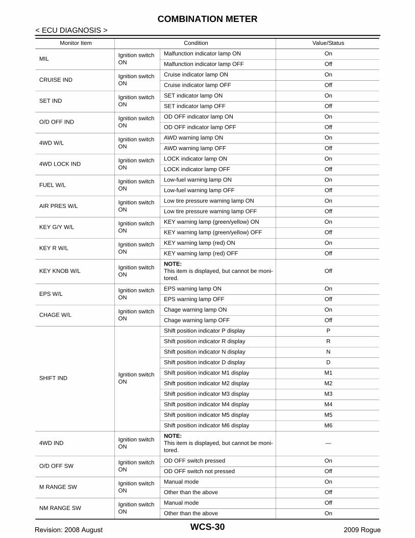
Reference Value INFOID:0000000004535259
VALUES ON THE DIAGNOSIS TOOL
Monitor Item Condition Value/Status
SPEED METER[km/h]
Ignition switch ON
While driving
Equivalent to speedometer readingNOTE:655.35 is displayed when the malfunc-tion signal is received
SPEED OUTPUT[km/h]
Ignition switch ON
While driving
Equivalent to speedometer readingNOTE:655.35 is displayed when the malfunc-tion signal is received
ODO OUTPUTIgnition switch ON
—Equivalent to odometer reading in combination meter
TACHO METER[rpm]
Ignition switch ON
While driving
Equivalent to tachometer readingNOTE:8191.875 is displayed when the mal-function signal is received
FUEL METER[lit]
Ignition switch ON
— Values according to fuel level
W TEMP METER[°C]
Ignition switch ON
—
Values according to engine coolant temperatureNOTE:215 is displayed when the malfunction signal is input
INST FUEL[km/l]
Ignition switch ON
NOTE:This item is displayed, but cannot be moni-tored.
—
ABS W/LIgnition switch ON
ABS warning lamp ON On
ABS warning lamp OFF Off
VDC/TCS INDIgnition switch ON
VDC OFF indicator lamp ON On
VDC OFF indicator lamp OFF Off
SLIP INDIgnition switch ON
SLIP indicator lamp ON On
SLIP indicator lamp OFF Off
BRAKE W/LIgnition switch ON
Brake warning lamp ON On
Brake warning lamp OFF Off
DOOR W/LIgnition switch ON
Door warning lamp ON On
Door warning lamp OFF Off
HI-BEAM INDIgnition switch ON
High beam indicator lamp ON On
High beam indicator lamp OFF Off
TURN INDIgnition switch ON
Turn signal indicator lamp ON On
Turn signal indicator lamp OFF Off
LIGHT INDIgnition switch ON
Light indicator lamp ON On
Light indicator lamp OFF Off
OIL W/L Ignition switch ON
Oil pressure warning lamp ON On
Oil pressure warning lamp OFF Off
WCS-29Revision: 2008 August 2009 Rogue
COMBINATION METER
< ECU DIAGNOSIS >MILIgnition switch ON
Malfunction indicator lamp ON On
Malfunction indicator lamp OFF Off
CRUISE INDIgnition switch ON
Cruise indicator lamp ON On
Cruise indicator lamp OFF Off
SET INDIgnition switch ON
SET indicator lamp ON On
SET indicator lamp OFF Off
O/D OFF INDIgnition switch ON
OD OFF indicator lamp ON On
OD OFF indicator lamp OFF Off
4WD W/LIgnition switch ON
AWD warning lamp ON On
AWD warning lamp OFF Off
4WD LOCK INDIgnition switch ON
LOCK indicator lamp ON On
LOCK indicator lamp OFF Off
FUEL W/LIgnition switch ON
Low-fuel warning lamp ON On
Low-fuel warning lamp OFF Off
AIR PRES W/LIgnition switch ON
Low tire pressure warning lamp ON On
Low tire pressure warning lamp OFF Off
KEY G/Y W/L Ignition switch ON
KEY warning lamp (green/yellow) ON On
KEY warning lamp (green/yellow) OFF Off
KEY R W/L Ignition switch ON
KEY warning lamp (red) ON On
KEY warning lamp (red) OFF Off
KEY KNOB W/LIgnition switch ON
NOTE:This item is displayed, but cannot be moni-tored.
Off
EPS W/LIgnition switch ON
EPS warning lamp ON On
EPS warning lamp OFF Off
CHAGE W/LIgnition switch ON
Chage warning lamp ON On
Chage warning lamp OFF Off
SHIFT INDIgnition switch ON
Shift position indicator P display P
Shift position indicator R display R
Shift position indicator N display N
Shift position indicator D display D
Shift position indicator M1 display M1
Shift position indicator M2 display M2
Shift position indicator M3 display M3
Shift position indicator M4 display M4
Shift position indicator M5 display M5
Shift position indicator M6 display M6
4WD INDIgnition switch ON
NOTE:This item is displayed, but cannot be moni-tored.
—
O/D OFF SWIgnition switch ON
OD OFF switch pressed On
OD OFF switch not pressed Off
M RANGE SWIgnition switch ON
Manual mode On
Other than the above Off
NM RANGE SWIgnition switch ON
Manual mode Off
Other than the above On
Monitor Item Condition Value/Status
WCS-30Revision: 2008 August 2009 Rogue

CS
COMBINATION METER
C
D
E
F
G
H
I
J
K
L
M
B
A
O
P
W
< ECU DIAGNOSIS >
NOTE:
Some items are
TERMINAL LAYOUT
PHYSICAL VALUES
AT SFT UP SWIgnition switch ON
Selector lever (+) position On
Other than the above Off
AT SFT DWN SWIgnition switch ON
Selector lever (–) position On
Other than the above Off
ST SFT UP SWIgnition switch ON
Paddle shifter up operation On
Other than the above Off
ST SFT DWN SWIgnition switch ON
Paddle shifter down operation On
Other than the above Off
PKB SWIgnition switch ON
Parking brake switch ON On
Parking brake switch OFF Off
BUCKLE SWIgnition switch ON
Seat belt buckle switch ON On
Seat belt buckle switch OFF Off
BRAKE OIL SWIgnition switch ON
Brake fluid level switch ON On
Brake fluid level switch OFF Off
DISTANCE[km]
Ignition switch ON
—Possible driving distance calculated by combination meter
OUTSIDE TEMP[°C or °F]
Ignition switch ON
—
Equivalent to ambient air temperatureNOTE:This may not match the indicated value on the information display.
FUEL LOW SIGIgnition switch ON
Low-fuel warning displayed On
Low-fuel warning not displayed Off
BUZZERIgnition switch ON
Buzzer ON On
Buzzer OFF Off
Monitor Item Condition Value/Status
JSNIA0457ZZ
Terminal No.(Wire color)
Description
ConditionValue
(Approx.)+ – Signal name
Input/Output
1(LG)
Ground Battery power supply InputIgnition switch OFF
— Battery voltage
2(O)
Ground Ignition signal InputIgnition switch ON
— Battery voltage
WCS-31Revision: 2008 August 2009 Rogue

COMBINATION METER
< ECU DIAGNOSIS >3(B)
Ground Ground —Ignition switch ON
— 0 V
9(GR)
Ground O/D OFF switch signal InputIgnition switch ON
O/D OFF switch pressed 0 V
O/D OFF switch not pressed
12 V
12(G)
Ground Paddle shifter down signal InputIgnition switch ON
Paddle shifter down opera-tion
0 V
Other than the above 12 V
13(Y)
Ground Illumination control signal InputIgnition switch ON
Lighting switch ON, then operate the illumination control switch
NOTE:When brightness level is midway
14(L)
Ground Paddle shifter up signal InputIgnition switch ON
Paddle shifter up operation 0 V
Other than the above 5 V
15(LG)
Ground Air bag signal InputIgnition switch ON
Air bag warning lampON
4 V
Air bag warning lampOFF
0 V
19(BR)
Ground Ambient sensor signal InputIgnition switch ON
—
20(SB)
Ground Ambient sensor ground —Ignition switch ON
— 0 V
21(L)
— CAN-H — — — —
22(P)
— CAN-L — — — —
23(B)
Ground Ground —Ignition switch ON
— 0 V
24(B)
GroundFuel level sensor signal ground
—Ignition switch ON
— 0 V
25(SB)
Ground Alternator signal InputIgnition switch ON
Charge warning lamp ON 0 V
Charge warning lamp OFF 12 V
26(V)
Ground Parking brake switch signal InputIgnition switch ON
Parking brake ON 0 V
Parking brake OFF 5 V
Terminal No.(Wire color)
Description
ConditionValue
(Approx.)+ – Signal name
Input/Output
JSNIA0010GB
JSNIA0014GB
WCS-32Revision: 2008 August 2009 Rogue
CS
COMBINATION METER
C
D
E
F
G
H
I
J
K
L
M
B
A
O
P
W
< ECU DIAGNOSIS >
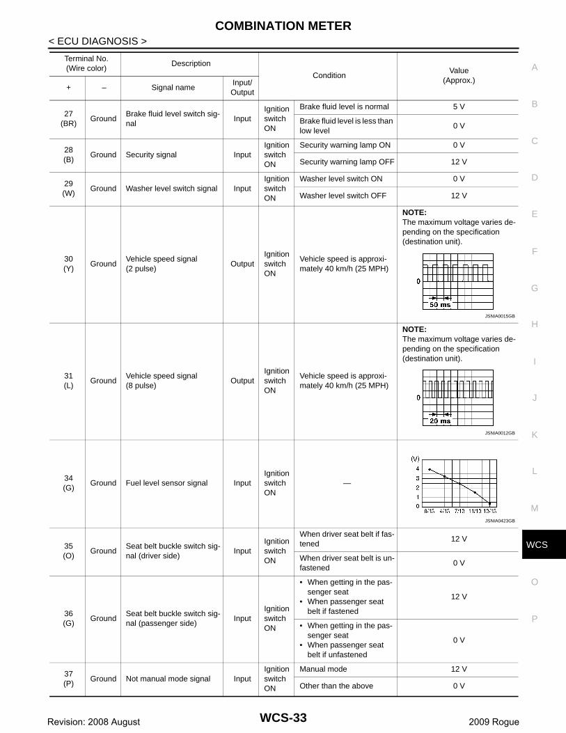
27(BR)
GroundBrake fluid level switch sig-nal
InputIgnition switch ON
Brake fluid level is normal 5 V
Brake fluid level is less than low level
0 V
28(B)
Ground Security signal InputIgnition switch ON
Security warning lamp ON 0 V
Security warning lamp OFF 12 V
29(W)
Ground Washer level switch signal InputIgnition switch ON
Washer level switch ON 0 V
Washer level switch OFF 12 V
30(Y)
GroundVehicle speed signal(2 pulse)
OutputIgnition switch ON
Vehicle speed is approxi-mately 40 km/h (25 MPH)
NOTE:The maximum voltage varies de-pending on the specification (destination unit).
31(L)
GroundVehicle speed signal(8 pulse)
OutputIgnition switch ON
Vehicle speed is approxi-mately 40 km/h (25 MPH)
NOTE:The maximum voltage varies de-pending on the specification (destination unit).
34(G)
Ground Fuel level sensor signal InputIgnition switch ON
—
35(O)
GroundSeat belt buckle switch sig-nal (driver side)
InputIgnition switch ON
When driver seat belt if fas-tened
12 V
When driver seat belt is un-fastened
0 V
36(G)
GroundSeat belt buckle switch sig-nal (passenger side)
InputIgnition switch ON
• When getting in the pas-senger seat
• When passenger seat belt if fastened
12 V
• When getting in the pas-senger seat
• When passenger seat belt if unfastened
0 V
37(P)
Ground Not manual mode signal InputIgnition switch ON
Manual mode 12 V
Other than the above 0 V
Terminal No.(Wire color)
Description
ConditionValue
(Approx.)+ – Signal name
Input/Output
JSNIA0015GB
JSNIA0012GB
JSNIA0423GB
WCS-33Revision: 2008 August 2009 Rogue

COMBINATION METER
< ECU DIAGNOSIS >38(O)
GroundManual mode shift down signal
InputIgnition switch ON
Selector lever (–) position 0 V
Other than the above 12 V
39(V)
GroundManual mode shift up sig-nal
InputIgnition switch ON
Selector lever (+) position 0 V
Other than the above 12 V
40(LG)
Ground Manual mode signal InputIgnition switch ON
Manual mode 0 V
Other than the above 12 V
Terminal No.(Wire color)
Description
ConditionValue
(Approx.)+ – Signal name
Input/Output
WCS-34Revision: 2008 August 2009 Rogue

CS
COMBINATION METER
C
D
E
F
G
H
I
J
K
L
M
B
A
O
P
W
< ECU DIAGNOSIS >
Wiring Diagram - METER - INFOID:0000000004535260
JCNWM1623GB
WCS-35Revision: 2008 August 2009 Rogue

COMBINATION METER
< ECU DIAGNOSIS >JCNWM1624GB
WCS-36Revision: 2008 August 2009 Rogue

CS
COMBINATION METER
C
D
E
F
G
H
I
J
K
L
M
B
A
O
P
W
< ECU DIAGNOSIS >
JCNWM1625GB
WCS-37Revision: 2008 August 2009 Rogue

COMBINATION METER
< ECU DIAGNOSIS >JCNWM1626GB
WCS-38Revision: 2008 August 2009 Rogue

CS
COMBINATION METER
C
D
E
F
G
H
I
J
K
L
M
B
A
O
P
W
< ECU DIAGNOSIS >
JCNWM1627GB
WCS-39Revision: 2008 August 2009 Rogue

COMBINATION METER
< ECU DIAGNOSIS >JCNWM1628GB
WCS-40Revision: 2008 August 2009 Rogue

CS
COMBINATION METER
C
D
E
F
G
H
I
J
K
L
M
B
A
O
P
W
< ECU DIAGNOSIS >
JCNWM1629GB
WCS-41Revision: 2008 August 2009 Rogue

COMBINATION METER
< ECU DIAGNOSIS >JCNWM1630GB
WCS-42Revision: 2008 August 2009 Rogue

CS
COMBINATION METER
C
D
E
F
G
H
I
J
K
L
M
B
A
O
P
W
< ECU DIAGNOSIS >
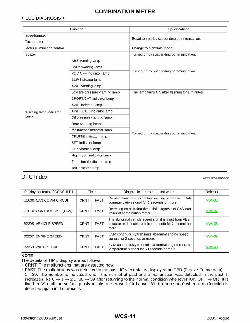
Fail-safe INFOID:0000000004535261
The combination meter activates the fail-safe control if the CAN communication lines between each unit aremalfunctioning.
JCNWM1653GB
WCS-43Revision: 2008 August 2009 Rogue
COMBINATION METER
< ECU DIAGNOSIS >DTC Index INFOID:0000000004535262
NOTE:The details of TIME display are as follows.• CRNT: The malfunctions that are detected now.• PAST: The malfunctions was detected in the past. IGN counter is displayed on FED (Freeze Frame data).- 1 - 39: The number is indicated when it is normal at past and a malfunction was detected in the past. It
increases like 0 → 1 → 2 ... 38 → 39 after returning to the normal condition whenever IGN OFF → ON. It isfixed to 39 until the self-diagnosis results are erased if it is over 39. It returns to 0 when a malfunction isdetected again in the process.
Function Specifications
SpeedometerReset to zero by suspending communication.
Tachometer
Meter illumination control Change to nighttime mode.
Buzzer Turned off by suspending communication.
Warning lamp/indicator lamp
ABS warning lamp
Turned on by suspending communication.Brake warning lamp
VDC OFF indicator lamp
SLIP indicator lamp
AWD warning lamp
Low tire pressure warning lamp The lamp turns ON after flashing for 1 minutes
SPORT/CVT indicator lamp
Turned off by suspending communication.
AWD indicator lamp
AWD LOCK indicator lamp
Oil pressure warning lamp
Door warning lamp
Malfunction indicator lamp
CRUISE indicator lamp
SET indicator lamp
KEY warning lamp
High beam indicator lamp
Turn signal indicator lamp
Tail indicator lamp
Display contents of CONSULT-III Time Diagnostic item is detected when... Refer to
U1000: CAN COMM CIRCUIT CRNT PASTCombination meter is not transmitting or receiving CAN communication signal for 2 seconds or more.
MWI-36
U1010: CONTROL UNIT (CAN) CRNT PASTDetecting error during the initial diagnosis of CAN con-troller of combination meter.
MWI-37
B2205: VEHICLE SPEED CRNT PASTThe abnormal vehicle speed signal is input from ABS actuator and electric unit (control unit) for 2 seconds or more.
MWI-38
B2267: ENGINE SPEED CRNT PASTECM continuously transmits abnormal engine speed signals for 2 seconds or more.
MWI-39
B2268: WATER TEMP CRNT PASTECM continuously transmits abnormal engine coolant temperature signals for 60 seconds or more.
MWI-40
WCS-44Revision: 2008 August 2009 Rogue

CS
BCM (BODY CONTROL MODULE)
C
D
E
F
G
H
I
J
K
L
M
B
A
O
P
W
< ECU DIAGNOSIS >
BCM (BODY CONTROL MODULE)
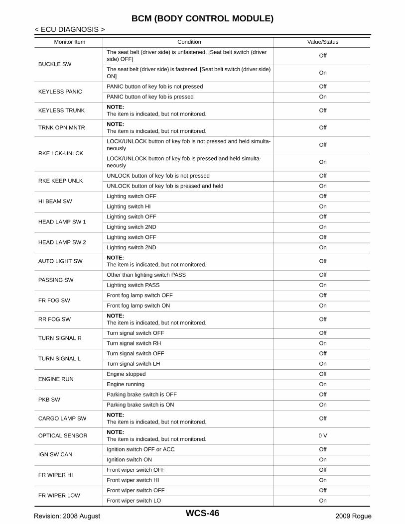
Reference Value INFOID:0000000004553944
VALUES ON THE DIAGNOSIS TOOL
Monitor Item Condition Value/Status
IGN ON SWIgnition switch OFF or ACC Off
Ignition switch ON On
KEY ON SWMechanical key is removed from key cylinder Off
Mechanical key is inserted to key cylinder On
CDL LOCK SWDoor lock/unlock switch does not operate Off
Press door lock/unlock switch to the lock side On
CDL UNLOCK SWDoor lock/unlock switch does not operate Off
Press door lock/unlock switch to the unlock side On
DOOR SW-DRDriver's door closed Off
Driver's door opened On
DOOR SW-ASPassenger door closed Off
Passenger door opened On
DOOR SW-RRRear RH door closed Off
Rear RH door opened On
DOOR SW-RLRear LH door closed Off
Rear LH door opened On
BACK DOOR SWBack door closed Off
Back door opened On
KEY CYL LK-SWOther than driver door key cylinder LOCK position Off
Driver door key cylinder LOCK position On
KEY CYL UN-SWOther than driver door key cylinder UNLOCK position Off
Driver door key cylinder UNLOCK position On
KEYLESS LOCK“LOCK” button of key fob is not pressed Off
“LOCK” button of key fob is pressed On
KEYLESS UNLOCK“UNLOCK” button of key fob is not pressed Off
“UNLOCK” button of key fob is pressed On
I-KEY LOCK
“LOCK” button of Intelligent Key or door request switch are not pressed
Off
“LOCK” button of Intelligent Key or door request switch are pressed On
I-KEY UNLOCK
“UNLOCK” button of Intelligent Key or door request switch are not pressed
Off
“UNLOCK” button of Intelligent Key or door request switch are pressed
On
ACC ON SWIgnition switch OFF Off
Ignition switch ACC or ON On
REAR DEF SWRear window defogger switch OFF Off
Rear window defogger switch ON On
LIGHT SW 1STLighting switch OFF Off
Lighting switch 1ST On
WCS-45Revision: 2008 August 2009 Rogue
BCM (BODY CONTROL MODULE)
< ECU DIAGNOSIS >BUCKLE SW
The seat belt (driver side) is unfastened. [Seat belt switch (driver side) OFF]
Off
The seat belt (driver side) is fastened. [Seat belt switch (driver side) ON]
On
KEYLESS PANICPANIC button of key fob is not pressed Off
PANIC button of key fob is pressed On
KEYLESS TRUNKNOTE:The item is indicated, but not monitored.
Off
TRNK OPN MNTRNOTE:The item is indicated, but not monitored.
Off
RKE LCK-UNLCK
LOCK/UNLOCK button of key fob is not pressed and held simulta-neously
Off
LOCK/UNLOCK button of key fob is pressed and held simulta-neously
On
RKE KEEP UNLKUNLOCK button of key fob is not pressed Off
UNLOCK button of key fob is pressed and held On
HI BEAM SWLighting switch OFF Off
Lighting switch HI On
HEAD LAMP SW 1Lighting switch OFF Off
Lighting switch 2ND On
HEAD LAMP SW 2Lighting switch OFF Off
Lighting switch 2ND On
AUTO LIGHT SWNOTE:The item is indicated, but not monitored.
Off
PASSING SWOther than lighting switch PASS Off
Lighting switch PASS On
FR FOG SWFront fog lamp switch OFF Off
Front fog lamp switch ON On
RR FOG SWNOTE:The item is indicated, but not monitored.
Off
TURN SIGNAL RTurn signal switch OFF Off
Turn signal switch RH On
TURN SIGNAL LTurn signal switch OFF Off
Turn signal switch LH On
ENGINE RUNEngine stopped Off
Engine running On
PKB SWParking brake switch is OFF Off
Parking brake switch is ON On
CARGO LAMP SWNOTE:The item is indicated, but not monitored.
Off
OPTICAL SENSORNOTE:The item is indicated, but not monitored.
0 V
IGN SW CANIgnition switch OFF or ACC Off
Ignition switch ON On
FR WIPER HIFront wiper switch OFF Off
Front wiper switch HI On
FR WIPER LOWFront wiper switch OFF Off
Front wiper switch LO On
Monitor Item Condition Value/Status
WCS-46Revision: 2008 August 2009 Rogue
CS
BCM (BODY CONTROL MODULE)
C
D
E
F
G
H
I
J
K
L
M
B
A
O
P
W
< ECU DIAGNOSIS >
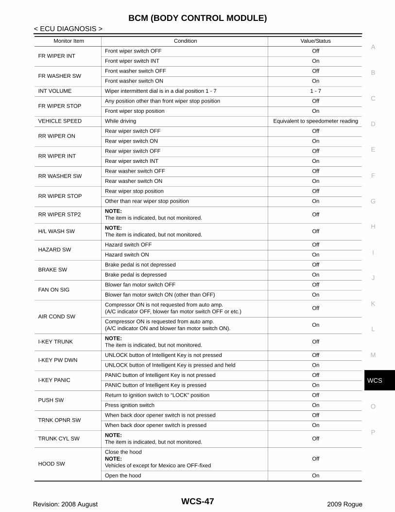
FR WIPER INTFront wiper switch OFF Off
Front wiper switch INT On
FR WASHER SWFront washer switch OFF Off
Front washer switch ON On
INT VOLUME Wiper intermittent dial is in a dial position 1 - 7 1 - 7
FR WIPER STOPAny position other than front wiper stop position Off
Front wiper stop position On
VEHICLE SPEED While driving Equivalent to speedometer reading
RR WIPER ON Rear wiper switch OFF Off
Rear wiper switch ON On
RR WIPER INTRear wiper switch OFF Off
Rear wiper switch INT On
RR WASHER SWRear washer switch OFF Off
Rear washer switch ON On
RR WIPER STOPRear wiper stop position Off
Other than rear wiper stop position On
RR WIPER STP2NOTE:The item is indicated, but not monitored.
Off
H/L WASH SWNOTE:The item is indicated, but not monitored.
Off
HAZARD SWHazard switch OFF Off
Hazard switch ON On
BRAKE SWBrake pedal is not depressed Off
Brake pedal is depressed On
FAN ON SIGBlower fan motor switch OFF Off
Blower fan motor switch ON (other than OFF) On
AIR COND SW
Compressor ON is not requested from auto amp.(A/C indicator OFF, blower fan motor switch OFF or etc.)
Off
Compressor ON is requested from auto amp.(A/C indicator ON and blower fan motor switch ON).
On
I-KEY TRUNKNOTE:The item is indicated, but not monitored.
Off
I-KEY PW DWNUNLOCK button of Intelligent Key is not pressed Off
UNLOCK button of Intelligent Key is pressed and held On
I-KEY PANICPANIC button of Intelligent Key is not pressed Off
PANIC button of Intelligent Key is pressed On
PUSH SWReturn to ignition switch to “LOCK” position Off
Press ignition switch On
TRNK OPNR SWWhen back door opener switch is not pressed Off
When back door opener switch is pressed On
TRUNK CYL SWNOTE:The item is indicated, but not monitored.
Off
HOOD SW
Close the hoodNOTE:Vehicles of except for Mexico are OFF-fixed
Off
Open the hood On
Monitor Item Condition Value/Status
WCS-47Revision: 2008 August 2009 Rogue

BCM (BODY CONTROL MODULE)
< ECU DIAGNOSIS >OIL PRESS SW
• Ignition switch OFF or ACC• Engine running
Off
Ignition switch ON On
AIR PRESS FLIgnition switch ON (Only when the signal from the transmitter is re-ceived)
Air pressure of front LH tire
AIR PRESS FRIgnition switch ON (Only when the signal from the transmitter is re-ceived)
Air pressure of front RH tire
AIR PRESS RRIgnition switch ON (Only when the signal from the transmitter is re-ceived)
Air pressure of rear RH tire
AIR PRESS RLIgnition switch ON (Only when the signal from the transmitter is re-ceived)
Air pressure of rear LH tire
ID REGST FL1ID of front LH tire transmitter is registered Done
ID of front LH tire transmitter is not registered Yet
ID REGST FR1ID of front RH tire transmitter is registered Done
ID of front RH tire transmitter is not registered Yet
ID REGST RR1ID of rear RH tire transmitter is registered Done
ID of rear RH tire transmitter is not registered Yet
ID REGST RL1ID of rear LH tire transmitter is registered Done
ID of rear LH tire transmitter is not registered Yet
WARNING LAMPTire pressure indicator OFF Off
Tire pressure indicator ON On
BUZZERTire pressure warning alarm is not sounding Off
Tire pressure warning alarm is sounding On
Monitor Item Condition Value/Status
WCS-48Revision: 2008 August 2009 Rogue

CS
BCM (BODY CONTROL MODULE)
C
D
E
F
G
H
I
J
K
L
M
B
A
O
P
W
< ECU DIAGNOSIS >
TERMINAL LAYOUT
PHYSICAL VALUESCAUTION:• Check combination switch system terminal waveform under the loaded condition with lighting
switch, turn signal switch and wiper switch OFF is not to be fluctuated by being overloaded.• Turn wiper intermittent dial position to 4 except when checking waveform or voltage of wiper inter-
mittent dial position. Wiper intermittent dial position can be confirmed on CONSULT-III. Refer toBCS-27, "COMB SW : CONSULT-III Function (BCM - COMB SW)".
• BCM reads the status of the combination switch at 10 ms internal normally. Refer to BCS-9, "SystemDiagram".
JSMIA0046ZZ
Terminal No.(Wire color)
Description
ConditionValue
(Approx.)Signal nameInput/ Output+ −
1(V)
GroundIgnition key hole illu-mination control
OutputIgnition key hole illumination
OFF Battery voltage
ON 0 V
WCS-49Revision: 2008 August 2009 Rogue
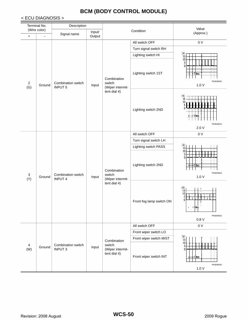
BCM (BODY CONTROL MODULE)
< ECU DIAGNOSIS >2(G)
GroundCombination switch INPUT 5
Input
Combination switch(Wiper intermit-tent dial 4)
All switch OFF 0 V
Turn signal switch RH
1.0 V
Lighting switch HI
Lighting switch 1ST
Lighting switch 2ND
2.0 V
3(Y)
GroundCombination switch INPUT 4
Input
Combination switch(Wiper intermit-tent dial 4)
All switch OFF 0 V
Turn signal switch LH
1.0 V
Lighting switch PASS
Lighting switch 2ND
Front fog lamp switch ON
0.8 V
4(W)
GroundCombination switch INPUT 3
Input
Combination switch(Wiper intermit-tent dial 4)
All switch OFF 0 V
Front wiper switch LO
1.0 V
Front wiper switch MIST
Front wiper switch INT
Terminal No.(Wire color)
Description
ConditionValue
(Approx.)Signal nameInput/ Output+ −
PKIB4959J
PKIB4953J
PKIB4959J
PKIB4955J
PKIB4959J
WCS-50Revision: 2008 August 2009 Rogue
CS
BCM (BODY CONTROL MODULE)
C
D
E
F
G
H
I
J
K
L
M
B
A
O
P
W
< ECU DIAGNOSIS >
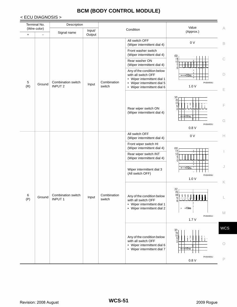
5(R)
GroundCombination switch INPUT 2
InputCombination switch
All switch OFF(Wiper intermittent dial 4)
0 V
Front washer switch(Wiper intermittent dial 4)
1.0 V
Rear washer ON(Wiper intermittent dial 4)
Any of the condition below with all switch OFF• Wiper intermittent dial 1• Wiper intermittent dial 5• Wiper intermittent dial 6
Rear wiper switch ON(Wiper intermittent dial 4)
0.8 V
6(P)
GroundCombination switch INPUT 1
InputCombination switch
All switch OFF(Wiper intermittent dial 4)
0 V
Front wiper switch HI(Wiper intermittent dial 4)
1.0 V
Rear wiper switch INT(Wiper intermittent dial 4)
Wiper intermittent dial 3(All switch OFF)
Any of the condition below with all switch OFF• Wiper intermittent dial 1• Wiper intermittent dial 2
1.7 V
Any of the condition below with all switch OFF• Wiper intermittent dial 6• Wiper intermittent dial 7
0.8 V
Terminal No.(Wire color)
Description
ConditionValue
(Approx.)Signal nameInput/ Output+ −
PKIB4959J
PKIB4955J
PKIB4959J
PKIB4952J
PKIB4955J
WCS-51Revision: 2008 August 2009 Rogue

BCM (BODY CONTROL MODULE)
< ECU DIAGNOSIS >7(L)
GroundDoor key cylinder switch UNLOCK sig-nal
InputDoor key cylin-der switch
NEUTRAL position
8.0 - 8.5 V
UNLOCK position 0 V
8(R)
GroundDoor key cylinder switch LOCK signal
InputDoor key cylin-der switch
NEUTRAL position
8.0 - 8.5 V
LOCK position 0 V
9(R)
Ground Stop lamp switch InputStop lamp switch
OFF (Brake pedal is not depressed)
0 V
ON (Brake pedal is de-pressed)
Battery voltage
10(SB)
GroundRear window defog-ger switch
InputRear window defogger switch
Not pressed Battery voltage
Pressed 0 V
11(SB)
Ground Ignition switch ACC InputIgnition switch OFF 0 V
Ignition switch ACC or ON Battery voltage
12(P)
GroundPassenger door switch
InputPassenger door switch
OFF(When passenger door closed)
7.5 - 8.0 V
ON(When passenger door opened)
0 V
13(LG)
Ground Rear door switch RH InputRear door switch RH
OFF(When rear door RH closed)
8.0 - 8.5 V
ON(When rear door RH opened)
0 V
Terminal No.(Wire color)
Description
ConditionValue
(Approx.)Signal nameInput/ Output+ −
JPMIA0587GB
JPMIA0587GB
JPMIA0586GB
JPMIA0587GB
WCS-52Revision: 2008 August 2009 Rogue

CS
BCM (BODY CONTROL MODULE)
C
D
E
F
G
H
I
J
K
L
M
B
A
O
P
W
< ECU DIAGNOSIS >
15*
(O)Ground
Tire pressure warn-ing check switch
Input Ignition switch OFF
1.5 V
18*
(O)Ground
Remote keyless en-try receiver ground
Input Ignition switch ON 0 V
19*
(V)Ground
Remote keyless en-try receiver power supply
Input
Without Intelli-gent Key sys-tem
At any condition 5 V
With Intelligent Key system
• Ignition switch OFF• For 3 seconds after ig-
nition switch OFF to ON0 V
3 seconds or later after ig-nition switch OFF to ON
5 V
20*
(GR)Ground
Remote keyless en-try receiver signal
Input
Without Intelli-gent Key sys-tem
At any condition
NOTE:The wave form changes accord-ing to signal-receiving condition.
With Intelligent Key system
• Ignition switch OFF• For 3 seconds after ig-
nition switch OFF to ON0 V
3 seconds or later after ig-nition switch OFF to ON
NOTE:The wave form changes accord-ing to signal-receiving condition.
21(G)
GroundImmobilizer anten-na signal (Clock)
Input/Output
Ignition switch OFF Battery voltage
Terminal No.(Wire color)
Description
ConditionValue
(Approx.)Signal nameInput/ Output+ −
JPMIA0588GB
JPMIA0589GB
JPMIA0589GB
WCS-53Revision: 2008 August 2009 Rogue

BCM (BODY CONTROL MODULE)
< ECU DIAGNOSIS >23(B)
GroundSecurity indicator signal
InputSecurity indica-tor
ON 0 V
Blinking (Ignition switch OFF)
12.0 V
OFF Battery voltage
25(BR)
GroundImmobilizer anten-na signal (Rx, Tx)
Input/Output
Ignition switch OFF Battery voltage
27(Y)
Ground A/C switch Input
Ignition switch OFF
1.6 V
Ignition switch ON
A/C switch OFF
A/C switch ON 0 V
28(LG)
Ground Blower fan switch Input
Ignition switch OFF
7.0 - 7.5 V
Ignition switch ON
Blower fan switch OFF
Blower fan switch ON 0 V
29(W)
Ground Hazard switch Input Hazard switchOFF Battery voltage
ON 0 V
30(G)
GroundBack door opener switch
InputBack door opener switch
Not pressed Battery voltage
Pressed 0 V
Terminal No.(Wire color)
Description
ConditionValue
(Approx.)Signal nameInput/ Output+ −
JPMIA0590GB
JPMIA0591GB
JPMIA0592GB
WCS-54Revision: 2008 August 2009 Rogue
CS
BCM (BODY CONTROL MODULE)
C
D
E
F
G
H
I
J
K
L
M
B
A
O
P
W
< ECU DIAGNOSIS >
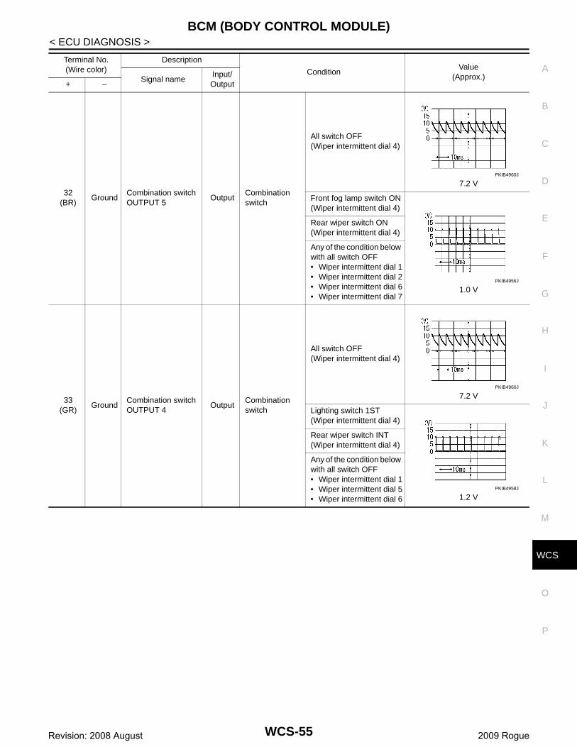
32(BR)
GroundCombination switch OUTPUT 5
OutputCombination switch
All switch OFF(Wiper intermittent dial 4)
7.2 V
Front fog lamp switch ON(Wiper intermittent dial 4)
1.0 V
Rear wiper switch ON(Wiper intermittent dial 4)
Any of the condition below with all switch OFF• Wiper intermittent dial 1• Wiper intermittent dial 2• Wiper intermittent dial 6• Wiper intermittent dial 7
33(GR)
GroundCombination switch OUTPUT 4
OutputCombination switch
All switch OFF(Wiper intermittent dial 4)
7.2 V
Lighting switch 1ST(Wiper intermittent dial 4)
1.2 V
Rear wiper switch INT(Wiper intermittent dial 4)
Any of the condition below with all switch OFF• Wiper intermittent dial 1• Wiper intermittent dial 5• Wiper intermittent dial 6
Terminal No.(Wire color)
Description
ConditionValue
(Approx.)Signal nameInput/ Output+ −
PKIB4960J
PKIB4956J
PKIB4960J
PKIB4958J
WCS-55Revision: 2008 August 2009 Rogue
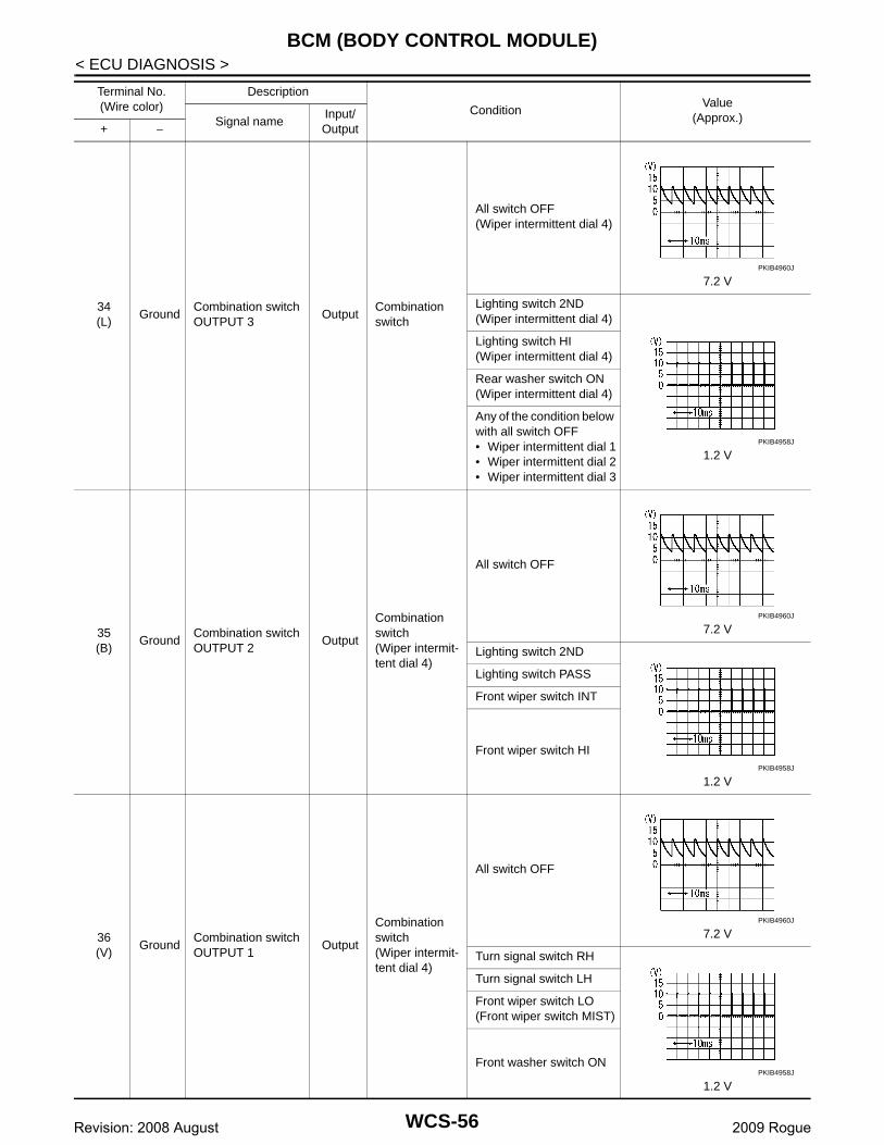
BCM (BODY CONTROL MODULE)
< ECU DIAGNOSIS >34(L)
GroundCombination switch OUTPUT 3
OutputCombination switch
All switch OFF(Wiper intermittent dial 4)
7.2 V
Lighting switch 2ND(Wiper intermittent dial 4)
1.2 V
Lighting switch HI(Wiper intermittent dial 4)
Rear washer switch ON(Wiper intermittent dial 4)
Any of the condition below with all switch OFF• Wiper intermittent dial 1• Wiper intermittent dial 2• Wiper intermittent dial 3
35(B)
GroundCombination switch OUTPUT 2
Output
Combination switch(Wiper intermit-tent dial 4)
All switch OFF
7.2 V
Lighting switch 2ND
1.2 V
Lighting switch PASS
Front wiper switch INT
Front wiper switch HI
36(V)
GroundCombination switch OUTPUT 1
Output
Combination switch(Wiper intermit-tent dial 4)
All switch OFF
7.2 V
Turn signal switch RH
1.2 V
Turn signal switch LH
Front wiper switch LO(Front wiper switch MIST)
Front washer switch ON
Terminal No.(Wire color)
Description
ConditionValue
(Approx.)Signal nameInput/ Output+ −
PKIB4960J
PKIB4958J
PKIB4960J
PKIB4958J
PKIB4960J
PKIB4958J
WCS-56Revision: 2008 August 2009 Rogue

CS
BCM (BODY CONTROL MODULE)
C
D
E
F
G
H
I
J
K
L
M
B
A
O
P
W
< ECU DIAGNOSIS >
37(LG)
Ground Key switch Input
Insert mechanical key into ignition key cylin-der
Battery voltage
Remove mechanical key from ignition key cylinder
0 V
38(G)
Ground Ignition switch ON InputIgnition switch OFF or ACC 0 V
Ignition switch ON or START Battery voltage
39(L)
Ground CAN-HInput/Output
— —
40(P)
Ground CAN-LInput/Output
— —
43(V)
Ground Back door switch InputBack door switch
OFF(When back door closed)
9.5 - 10.0 V
ON(When back door opened)
0 V
44(B)
Ground Rear wiper auto stop InputIgnition switch ON
Rear wiper stop position 0 V
Any position other than rear wiper stop position
Battery voltage
45(P)
GroundDoor lock and unlock switch LOCK signal
InputDoor lock and unlock switch
NEUTRAL position
1.6 V
LOCK position 0 V
46(BR)
GroundDoor lock and unlock switch UNLOCK sig-nal
InputDoor lock and unlock switch
NEUTRAL position
1.6 V
UNLOCK position 0 V
Terminal No.(Wire color)
Description
ConditionValue
(Approx.)Signal nameInput/ Output+ −
JPMIA0593GB
JPMIA0591GB
JPMIA0591GB
WCS-57Revision: 2008 August 2009 Rogue

BCM (BODY CONTROL MODULE)
< ECU DIAGNOSIS >47(W)
Ground Driver door switch InputDriver door switch
OFF(When driver door closed)
8.0 - 8.5 V
ON(When driver door opened)
0 V
48(GR)
Ground Rear door switch LH InputRear door switch LH
OFF(When rear door LH closed)
8.5 - 9.0 V
ON(When rear door LH opened)
0 V
49(L)
GroundBack door lamp con-trol
OutputBack door lamp switch DOOR position
Back door is closed(Back door lamp turns OFF)
Battery voltage
Back door is opened(Back door lamp turns ON)
0 V
53(V)
Ground Back door open OutputBack door opener switch
Not pressed(Back door actuator is ac-tivated)
0 V
Pressed(Back door actuator is ac-tivated)
Battery voltage
55(SB)
Ground Rear wiper motor OutputIgnition switch ON
Rear wiper switch OFF 0 V
Rear wiper switch ON Battery voltage
56(Y)
GroundInterior room lamp power supply
Output
After passing the interior room lamp battery saver operation time
0 V
Any other time after passing the interior room lamp battery saver operation time
Battery voltage
57(G)
GroundBattery power sup-ply
Input Ignition switch OFF Battery voltage
59(L)
GroundDriver door UN-LOCK
Output Driver door
UNLOCK (Actuator is acti-vated)
Battery voltage
Other then UNLOCK (Ac-tuator is not activated)
0 V
Terminal No.(Wire color)
Description
ConditionValue
(Approx.)Signal nameInput/ Output+ −
JPMIA0587GB
JPMIA0594GB
WCS-58Revision: 2008 August 2009 Rogue

CS
BCM (BODY CONTROL MODULE)
C
D
E
F
G
H
I
J
K
L
M
B
A
O
P
W
< ECU DIAGNOSIS >
*: Except for Mexico
60(BR)
Ground Turn signal LH OutputIgnition switch ON
Turn signal switch OFF 0 V
Turn signal switch LH
6.0 V
61(GR)
Ground Turn signal RH OutputIgnition switch ON
Turn signal switch OFF 0 V
Turn signal switch RH
6.0 V
63(R)
GroundInterior room lamp timer control
OutputInterior room lamp
OFF Battery voltage
ON 0 V
65(V)
Ground All doors LOCK Output All doors
LOCK (Actuator is activat-ed)
Battery voltage
Other then LOCK (Actua-tor is not activated)
0 V
66(G)
GroundPassenger door and rear door UNLOCK
OutputPassenger door and rear door
UNLOCK (Actuator is acti-vated)
Battery voltage
Other then UNLOCK (Ac-tuator is not activated)
0 V
67(B)
Ground Ground Output Ignition switch ON 0 V
68(L)
GroundP/W power supply (RAP)
Output Ignition switch ON Battery voltage
69(P)
GroundP/W power supply (BAT)
Output Ignition switch OFF Battery voltage
70(Y)
GroundBattery power sup-ply
Input Ignition switch OFF Battery voltage
Terminal No.(Wire color)
Description
ConditionValue
(Approx.)Signal nameInput/ Output+ −
PKIC6370E
PKIC6370E
WCS-59Revision: 2008 August 2009 Rogue

BCM (BODY CONTROL MODULE)
< ECU DIAGNOSIS >Wiring Diagram - BCM - INFOID:0000000004553945
JCMWM2850GB
WCS-60Revision: 2008 August 2009 Rogue
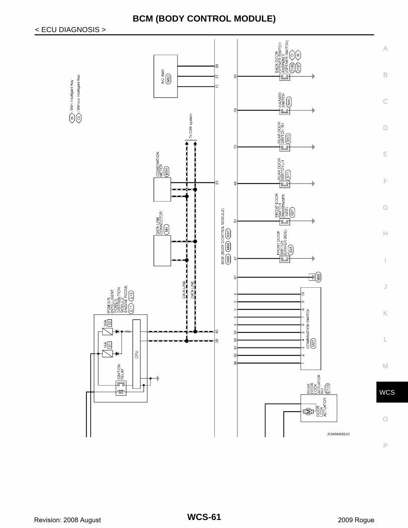
CS
BCM (BODY CONTROL MODULE)
C
D
E
F
G
H
I
J
K
L
M
B
A
O
P
W
< ECU DIAGNOSIS >
JCMWM2851GB
WCS-61Revision: 2008 August 2009 Rogue

BCM (BODY CONTROL MODULE)
< ECU DIAGNOSIS >JCMWM2852GB
WCS-62Revision: 2008 August 2009 Rogue

CS
BCM (BODY CONTROL MODULE)
C
D
E
F
G
H
I
J
K
L
M
B
A
O
P
W
< ECU DIAGNOSIS >
JCMWM2853GB
WCS-63Revision: 2008 August 2009 Rogue
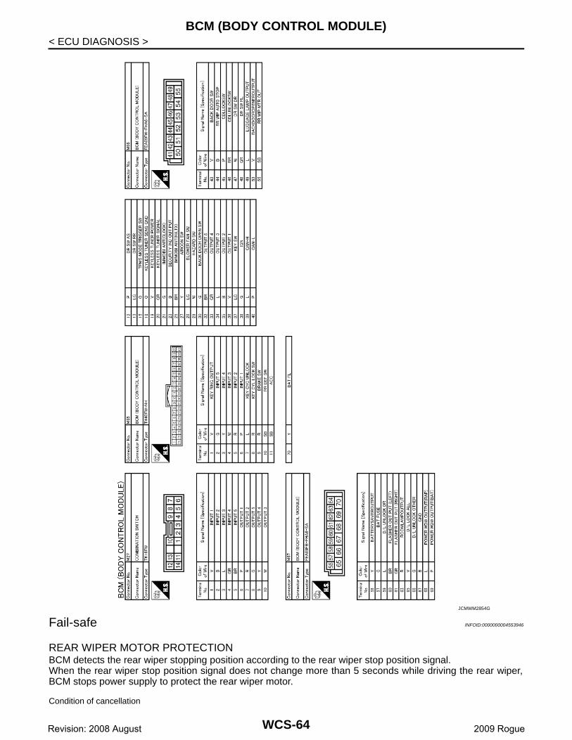
BCM (BODY CONTROL MODULE)
< ECU DIAGNOSIS >Fail-safe INFOID:0000000004553946
REAR WIPER MOTOR PROTECTIONBCM detects the rear wiper stopping position according to the rear wiper stop position signal.When the rear wiper stop position signal does not change more than 5 seconds while driving the rear wiper,BCM stops power supply to protect the rear wiper motor.
Condition of cancellation
JCMWM2854GB
WCS-64Revision: 2008 August 2009 Rogue
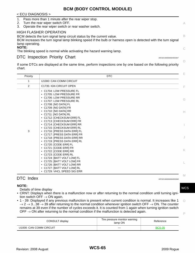
CS
BCM (BODY CONTROL MODULE)
C
D
E
F
G
H
I
J
K
L
M
B
A
O
P
W
< ECU DIAGNOSIS >1. Pass more than 1 minute after the rear wiper stop.2. Turn the rear wiper switch OFF.3. Operate the rear wiper switch or rear washer switch.
HIGH FLASHER OPERATIONBCM detects the turn signal lamp circuit status by the current value.BCM increases the turn signal lamp blinking speed if the bulb or harness open is detected with the turn signallamp operating.NOTE:The blinking speed is normal while activating the hazard warning lamp.
DTC Inspection Priority Chart INFOID:0000000004553947
If some DTCs are displayed at the same time, perform inspections one by one based on the following prioritychart.
DTC Index INFOID:0000000004553948
NOTE:Details of time display
• CRNT: Displays when there is a malfunction now or after returning to the normal condition until turning igni-tion switch OFF → ON again.
• 1 - 39: Displayed if any previous malfunction is present when current condition is normal. It increases like 1→ 2 → 3...38 → 39 after returning to the normal condition whenever ignition switch OFF → ON. The counterremains at 39 even if the number of cycles exceeds it. It is counted from 1 again when turning ignition switchOFF → ON after returning to the normal condition if the malfunction is detected again.
Priority DTC
1 U1000: CAN COMM CIRCUIT
2 C1735: IGN CIRCUIT OPEN
3
• C1704: LOW PRESSURE FL• C1705: LOW PRESSURE FR• C1706: LOW PRESSURE RR• C1707: LOW PRESSURE RL• C1708: [NO DATA] FL• C1709: [NO DATA] FR• C1710: [NO DATA] RR• C1711: [NO DATA] RL• C1712: [CHECKSUM ERR] FL• C1713: [CHECKSUM ERR] FR• C1714: [CHECKSUM ERR] RR• C1715: [CHECKSUM ERR] RL• C1716: [PRESS DATA ERR] FL• C1717: [PRESS DATA ERR] FR• C1718: [PRESS DATA ERR] RR• C1719: [PRESS DATA ERR] RL• C1720: [CODE ERR] FL• C1721: [CODE ERR] FR• C1722: [CODE ERR] RR• C1723: [CODE ERR] RL• C1724: [BATT VOLT LOW] FL• C1725: [BATT VOLT LOW] FR• C1726: [BATT VOLT LOW] RR• C1727: [BATT VOLT LOW] RL• C1729: VHCL SPEED SIG ERR
CONSULT displayTire pressure monitor warning
lamp ONReference
U1000: CAN COMM CIRCUIT — BCS-35
WCS-65Revision: 2008 August 2009 Rogue
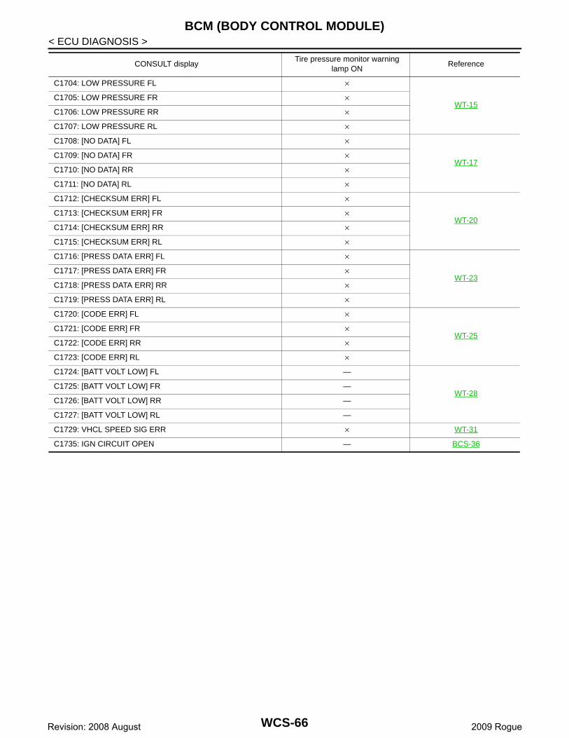
BCM (BODY CONTROL MODULE)
< ECU DIAGNOSIS >C1704: LOW PRESSURE FL ×
WT-15C1705: LOW PRESSURE FR ×
C1706: LOW PRESSURE RR ×
C1707: LOW PRESSURE RL ×
C1708: [NO DATA] FL ×
WT-17C1709: [NO DATA] FR ×
C1710: [NO DATA] RR ×
C1711: [NO DATA] RL ×
C1712: [CHECKSUM ERR] FL ×
WT-20C1713: [CHECKSUM ERR] FR ×
C1714: [CHECKSUM ERR] RR ×
C1715: [CHECKSUM ERR] RL ×
C1716: [PRESS DATA ERR] FL ×
WT-23C1717: [PRESS DATA ERR] FR ×
C1718: [PRESS DATA ERR] RR ×
C1719: [PRESS DATA ERR] RL ×
C1720: [CODE ERR] FL ×
WT-25C1721: [CODE ERR] FR ×
C1722: [CODE ERR] RR ×
C1723: [CODE ERR] RL ×
C1724: [BATT VOLT LOW] FL —
WT-28C1725: [BATT VOLT LOW] FR —
C1726: [BATT VOLT LOW] RR —
C1727: [BATT VOLT LOW] RL —
C1729: VHCL SPEED SIG ERR × WT-31
C1735: IGN CIRCUIT OPEN — BCS-36
CONSULT displayTire pressure monitor warning
lamp ONReference
WCS-66Revision: 2008 August 2009 Rogue
CS
THE LIGHT REMINDER WARNING DOES NOT SOUND
C
D
E
F
G
H
I
J
K
L
M
B
A
O
P
W
< SYMPTOM DIAGNOSIS >
SYMPTOM DIAGNOSISTHE LIGHT REMINDER WARNING DOES NOT SOUND
Description INFOID:0000000004236585
The light reminder warning chime does not sound under the following conditions.• Lighting switch 1ST or 2ND position• Driver door open• Ignition switch except ON or START
Diagnosis Procedure INFOID:0000000004236586
1.CHECK COMBINATION SWITCH (LIGHTING SWITCH) OPERATION
Check that the headlamps operate normally by operating the combination switch (lighting switch).Do they operate normally?YES >> GO TO 2.NO >> Refer to EXL-106, "Symptom Table" (xenon type), EXL-243, "Symptom Table" (halogen type).
2.CHECK FRONT DOOR SWITCH (DRIVER SIDE) SIGNAL CIRCUIT
Check the front door switch (driver side) signal circuit. Refer to DLK-55, "Diagnosis Procedure" (with IntelligentKey system), DLK-299, "Diagnosis Procedure" (without Intelligent Key system).Is the inspection result normal?YES >> GO TO 3.NO >> Repair harness or connector.
3.CHECK FRONT DOOR SWITCH (DRIVER SIDE)
Check the front door switch (driver side). Refer to DLK-57, "Component Inspection" (with Intelligent Key sys-tem), DLK-301, "Component Inspection" (without Intelligent Key system).Is the inspection result normal?YES >> Replace the BCM. Refer to BCS-67, "Removal and Installation".NO >> Replace the front door switch (driver side). Refer to DLK-263, "Removal and Installation".
WCS-67Revision: 2008 August 2009 Rogue
THE SEAT BELT REMINDER WARNING DOES NOT SOUND
< SYMPTOM DIAGNOSIS >THE SEAT BELT REMINDER WARNING DOES NOT SOUND
Description INFOID:0000000004236587
Seat belt reminder warning chime does not sound.
Trouble diagnosis procedure INFOID:0000000004236588
1.CHECK COMBINATION METER INPUT SIGNAL
1. Connect the CONSULT-III.2. Select the “Data Monitor” of “METER/M&A” and check the “BUCKLE SW” monitor value. Refer to WCS-
22, "Component Function Check".Is the inspection result normal?YES >> Replace combination meter.NO >> GO TO 2.
2.CHECK SEAT BELT BUCKLE SWITCH (DRIVER SIDE) SIGNAL CIRCUIT
Check the seat belt buckle switch (driver side) signal circuit. Refer to WCS-22, "Diagnosis Procedure". Is the inspection result normal?YES >> GO TO 3.NO >> Repair the harnesses or connectors.
3.CHECK SEAT BELT BUCKLE SWITCH (DRIVER SIDE)
Check the seat belt buckle switch (driver side). Refer to WCS-23, "Component Inspection". Is the inspection result normal?YES >> Replace combination meter.NO >> Replace the seat belt buckle switch (driver side). Refer to SB-8, "SEAT BELT BUCKLE : Removal
and Installation".
WCS-68Revision: 2008 August 2009 Rogue

CS
THE PARKING BRAKE RELEASE WARNING DOES NOT SOUND
C
D
E
F
G
H
I
J
K
L
M
B
A
O
P
W
< SYMPTOM DIAGNOSIS >
THE PARKING BRAKE RELEASE WARNING DOES NOT SOUND
Description INFOID:0000000004236589
The parking brake warning chime does not sound at all even though driving the vehicle with the parking brakeapplied.
Diagnosis Procedure INFOID:0000000004236590
1.CHECK PARKING BRAKE WARNING LAMP OPERATION
1. Connect the CONSULT-III.2. Select the “Data Monitor” of “METER/M&A” and check the “PKB SW” monitor value. Refer to WCS-22,
"Component Function Check".Is the inspection result normal?YES >> Replace combination meter.NO >> GO TO 2.
2.CHECK PARKING BRAKE SWITCH SIGNAL CIRCUIT
Check the parking brake switch signal circuit. Refer to WCS-24, "Diagnosis Procedure".Is the inspection result normal?YES >> GO TO 3.NO >> Repair harness or connector.
3.CHECK PARKING BRAKE SWITCH
Check the parking brake switch. Refer to WCS-24, "Component Inspection".Is the inspection result normal?YES >> Replace combination meter. Refer to MWI-86, "Removal and Installation".NO >> Replace parking brake switch.
WCS-69Revision: 2008 August 2009 Rogue

THE KEY WARNING DOES NOT SOUND
< SYMPTOM DIAGNOSIS >THE KEY WARNING DOES NOT SOUND
Description INFOID:0000000004236591
The key warning chime does not sound under the following conditions.• Key inserted into the ignition key cylinder (Key switch signal ON) • Ignition switch except in ON or START (Ignition switch signal OFF)• Front door switch (driver side) open. [Front door switch (driver side) signal ON]
Diagnosis Procedure INFOID:0000000004236592
1.CHECK BCM INPUT SIGNAL
1. Connect the CONSULT-III.2. Select the “Data Monitor” of “BCM (BUZZER)” and check the “KEY ON SW” monitor value. Refer to WCS-
29, "Reference Value".Is the inspection result normal?YES >> Replace Intelligent Key unit. Refer to DLK-271, "Exploded View".NO >> GO TO 2.
2.CHECK KEY SWITCH SIGNAL CIRCUIT
Check the key switch signal circuit. Refer to DLK-307, "Diagnosis Procedure".Is the inspection result normal?YES >> GO TO 3.NO >> Check applicable parts, and repair or replace corresponding parts.
3.CHECK FRONT DOOR SWITCH (DRIVER SIDE) SIGNAL CIRCUIT
Check the front door switch (driver side) signal circuit. Refer to DLK-299, "Diagnosis Procedure".Is the inspection result normal?YES >> GO TO 4.NO >> Repair harness or connector.
4.CHECK FRONT DOOR SWITCH (DRIVER SIDE)
Check the front door switch (driver side). Refer to DLK-301, "Component Inspection".Is the inspection result normal?YES >> Replace the BCM. Refer to BCS-67, "Exploded View".NO >> Replace the front door switch (driver side). Refer to DLK-450, "Exploded View".
WCS-70Revision: 2008 August 2009 Rogue

CS
PRECAUTIONS
C
D
E
F
G
H
I
J
K
L
M
B
A
O
P
W
< PRECAUTION >
PRECAUTIONPRECAUTIONSFOR USA AND CANADA
FOR USA AND CANADA : Precaution for Supplemental Restraint System (SRS) "AIR BAG" and "SEAT BELT PRE-TENSIONER" INFOID:0000000004553950
The Supplemental Restraint System such as “AIR BAG” and “SEAT BELT PRE-TENSIONER”, used alongwith a front seat belt, helps to reduce the risk or severity of injury to the driver and front passenger for certaintypes of collision. This system includes seat belt switch inputs and dual stage front air bag modules. The SRSsystem uses the seat belt switches to determine the front air bag deployment, and may only deploy one frontair bag, depending on the severity of a collision and whether the front occupants are belted or unbelted.Information necessary to service the system safely is included in the “SRS AIRBAG” and “SEAT BELT” of thisService Manual.WARNING:• To avoid rendering the SRS inoperative, which could increase the risk of personal injury or death in
the event of a collision which would result in air bag inflation, all maintenance must be performed byan authorized NISSAN/INFINITI dealer.
• Improper maintenance, including incorrect removal and installation of the SRS, can lead to personalinjury caused by unintentional activation of the system. For removal of Spiral Cable and Air BagModule, see the “SRS AIRBAG”.
• Never use electrical test equipment on any circuit related to the SRS unless instructed to in this Ser-vice Manual. SRS wiring harnesses can be identified by yellow and/or orange harnesses or harnessconnectors.
FOR MEXICO
FOR MEXICO : Precaution for Supplemental Restraint System (SRS) "AIR BAG" and "SEAT BELT PRE-TENSIONER" INFOID:0000000004553951
The Supplemental Restraint System such as “AIR BAG” and “SEAT BELT PRE-TENSIONER”, used alongwith a front seat belt, helps to reduce the risk or severity of injury to the driver and front passenger for certaintypes of collision. Information necessary to service the system safely is included in the “SRS AIRBAG” and“SEAT BELT” of this Service Manual.WARNING:• To avoid rendering the SRS inoperative, which could increase the risk of personal injury or death in
the event of a collision which would result in air bag inflation, all maintenance must be performed byan authorized NISSAN/INFINITI dealer.
• Improper maintenance, including incorrect removal and installation of the SRS, can lead to personalinjury caused by unintentional activation of the system. For removal of Spiral Cable and Air BagModule, see the “SRS AIRBAG”.
• Do not use electrical test equipment on any circuit related to the SRS unless instructed to in thisService Manual. SRS wiring harnesses can be identified by yellow and/or orange harnesses or har-ness connectors.
WCS-71Revision: 2008 August 2009 Rogue