DRIVE SHAFT GUIDE BEARING ATTACHMENT - … Library/JR Vibe... · · 2013-04-23Set Screw, 4 x 6 mm...
35
31 ..................... 4 pcs ........................1 pc Set Screw, 4 x 6 mm Washer, 5 x 9 x 1 mm Washer, 5 x 9 x 1 mm Use Green Threadlock Green Set Screw, 4 x 6 mm (4 pcs) Tail Drive Joint, Front Bevel Pinion Bearing Case Bevel Pinion Gear Flange Bevel Pinion Bearing Case Direction Green Flange must face bevel gear. Green Apply a thin coating of green threadlock to shaft pinion of assembly. Poly Zap Slide and spread. Poly Zap 260 mm/230 mm Poly Zap Wipe lightly w/finger or towel. Step A Step B Step C DRIVE SHAFT GUIDE BEARING ATTACHMENT Attach the tail drive joint and secure so that there is no fore/aft movement of the shaft, but the shaft will spin freely in the bearing assembly. 5-3 BEVEL PINION GEAR ASSEMBLY Note: Use Poly Zap (not included) to attach bearings to the drive shaft. Once the Poly Zap is applied and the guide bearings are in their correct positions (260 mm/230 mm), the Poly Zap can be quick cured using Zip Kicker. Position the shaft assembly on a flat surface before/while the Poly Zap is curing. It is very important that the guide bearings be attached to the shaft at non equal measurements as shown to prevent resonance vibration and fatigue. Lightly oil bearings after the glue has dried. Do not apply Poly Zap to inside of ball bearings. Note: 260 mm 230 mm Follow this procedure when attaching: Front Rear Bearing Positions Front Rear 5-2 continued
Transcript of DRIVE SHAFT GUIDE BEARING ATTACHMENT - … Library/JR Vibe... · · 2013-04-23Set Screw, 4 x 6 mm...

31
..................... 4 pcs
........................1 pc
Set Screw, 4 x 6 mm
Washer, 5 x 9 x 1 mm
Washer, 5 x 9 x 1 mm
Use Green Threadlock
Green
Set Screw, 4 x 6 mm (4 pcs)
Tail Drive Joint, Front
Bevel Pinion Bearing Case
Bevel Pinion Gear
Flange
Bevel Pinion Bearing Case Direction
Gre
en
Flange must face bevel gear.
Green
Apply a thin coating of green threadlock to shaft pinion of assembly.
Poly Zap
Slide and spread.Poly Zap
260 mm/230 mm
Poly Zap
Wipe lightly w/finger or towel.
Step A Step B Step C
DRIVE SHAFT GUIDE BEARING ATTACHMENT
Attach the tail drive joint andsecure so that there is nofore/aft movement of the shaft,but the shaft will spin freely in the bearing assembly.
5-3 BEVEL PINION GEAR ASSEMBLY
Note:
Use Poly Zap (not included) to attach bearings to the drive shaft.
Once the Poly Zap is applied and the guide bearings are in their correct positions (260 mm/230 mm), the Poly Zap can be quick cured using Zip Kicker.
Position the shaft assembly on a flat surface before/while the Poly Zap is curing.
It is very important that the guide bearings be attached to the shaft atnon equal measurements as shown to prevent resonance vibration and fatigue.
Lightly oil bearings after the glue has dried.
Do not apply Poly Zap to inside of ball bearings.
Note:
260 mm 230 mm
Follow this procedure when attaching:
Front Rear
Bearing PositionsFront Rear
5-2 continued

32
Socket Head Bolt, 3 x 40 mm
Nylon Lock Nut, 3 mm
..4 pcs
.................................. 4 pcs
Must be aligned.
Flat Washer, 3 mm
.................................... 4 pcs
Socket Head Bolt, 3 x 6 mm
........................... 2 pc
2 pc Aluminum Tail Boom Holder
1 pc Aluminum Tail Boom Holder
Bevel Pinion Gear Assembly
2 pc Aluminum Tail Boom Holder
Note proper direction during installation as bottom hole is offset to match frame.
5-4 TAIL BOOM/BEVEL PINION GEAR INSTALLATION/ADJUSTMENT
Step 1: Attach the 2pc front Tail Boom Holder to the frame using 2 3x6 mm Socket head Bolts. Please note that since the bolt holes have an offset, there is a Left and Right side to these clamps. Do not completely tighten these bolts until the gear mesh has been set.
Step 2: Insert the completed Bevel Pinion Gear assembly into the tail boom, and align the hole in the hub to the hole in the tail boom.
Step 3: Install the 1pc Rear Tail Boom Clamp to the boom.
Step 4: Insert the tail boom assembly into the frame, front clamps, and attach using the 4 3x40mm Socket Head Bolts as shown below.
To set the proper mesh, insert 1 thickness of paper (the same thickness as the pages of this manual) between the 2 bevel gears.
Next, push the tail boom assembly down so that there is no gear backlash with the paper in place.
Tighten the 4 tail boom mounting bolts. Next, remove the thickness of paper and check the gear mesh. There should be a very slight amount of backlash. If the backlash seems too much, repeat this procedure using thinner paper. If backlash can't be detected, double the paper thickness and retest.
It is better to set this gear mesh slightly tight, rather than loose, or damage to the bevel gear can occur during extreme 3D flying or tail blade contact with the ground.
Note:
BEVEL GEAR MESH ADJUSTMENTBefore tightening of the 4 tail boom mounting clamp bolts, it will be necessary to set the bevel gear to bevel pinion gear mesh by raising or lowering the tail boom assembly.
Tail Boom, 879 mm
1 pc Aluminum Tail Boom Holder
2 pc Aluminum Tail Boom Holder
Nylon Lock Nut, 3 mm (4 pcs)
Flat Washer, 3 mm (4 pcs)
*
*
Socket Head Bolt, 3 x 40 mm (4 pcs)
Socket Head Bolt, 3 x 6 mm (2pcs)
Socket Head Bolt, 3 x 6 mm (2pcs)
* Do not tighten bolts until bevel gear mesh has been adjusted.
*
*

33
Aluminum Tail Support Clamp, Upper
Aluminum Tail SupportClamp, Lower
Socket Head Bolt, 3 x 12 mm (2 pcs)*Do not tighten boltscompletely at this time.
5-5 TAIL SUPPORT CLAMP INSTALLATION
Socket Head Bolt, 3 x 12 mm
......... 2 pcs
Use Red Threadlock
5-6 TAIL BOOM BRACE ASSEMBLY
Socket Head Bolt, 2.6 x 12 mm
Socket Head Bolt, 2.6 x 12 mm (4 pcs)
Tail Brace Tube
Tail Brace Connector (4 pcs)
...........4 pcs
TEAM TIP: It is suggested thatthe Tail Brace Connectors bebonded to the Tail Brace Tubesusing either thick CA adhesive, or JB Weld.
Tail Support Clamp Direction
FRONT
Note offset in bolt hole location.
34
Socket Head Bolt3 x 22 mm (2 pcs)
Nylon Lock Nut3 mm (4 pcs)
2 pcs
Red
Flat Washer, 3 mm (2 pcs)
Flat Washer3 mm (2 pcs)
Socket HeadBolt, 3 x 8 mm (2 pcs)
Red
Aluminum Tail Support Clamp, Lower
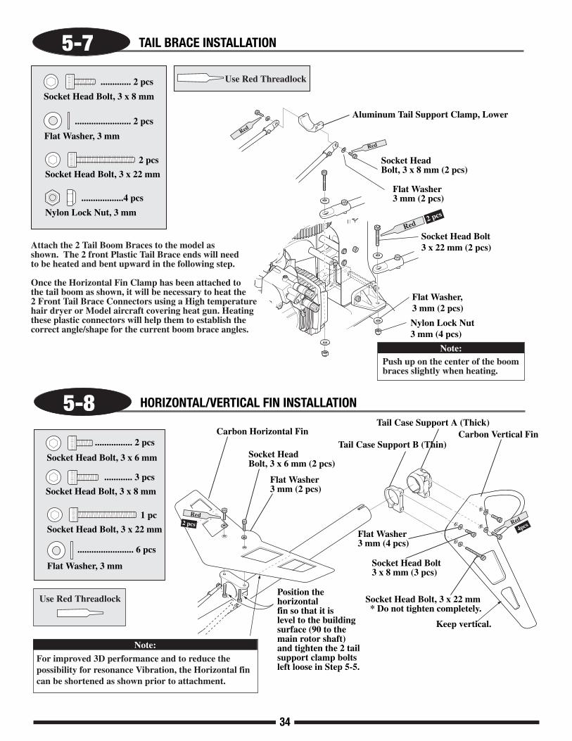
5-8 HORIZONTAL/VERTICAL FIN INSTALLATION
Flat Washer, 3 mm
........................ 6 pcs
Socket Head Bolt, 3 x 22 mm
1 pc
Socket Head Bolt, 3 x 8 mm
............ 3 pcs
Socket Head Bolt, 3 x 6 mm
................ 2 pcs
Use Red Threadlock
Flat Washer3 mm (4 pcs)
Socket Head Bolt, 3 x 22 mm * Do not tighten completely.
Socket Head Bolt3 x 8 mm (3 pcs)
Tail Case Support A (Thick)
Keep vertical.
Tail Case Support B (Thin)
4pcsRed
Socket HeadBolt, 3 x 6 mm (2 pcs)
Carbon Horizontal Fin
Flat Washer3 mm (2 pcs)
Position the horizontal fin so that it is level to the building surface (90 to the main rotor shaft) and tighten the 2 tailsupport clamp bolts left loose in Step 5-5.
Carbon Vertical Fin
Flat Washer, 3 mm
........................ 2 pcs
Socket Head Bolt, 3 x 8 mm
............. 2 pcs Use Red Threadlock
5-7 TAIL BRACE INSTALLATION
Socket Head Bolt, 3 x 22 mm
2 pcs
Red
Attach the 2 Tail Boom Braces to the model as shown. The 2 front Plastic Tail Brace ends will need to be heated and bent upward in the following step.
Once the Horizontal Fin Clamp has been attached to the tail boom as shown, it will be necessary to heat the 2 Front Tail Brace Connectors using a High temperature hair dryer or Model aircraft covering heat gun. Heating these plastic connectors will help them to establish the correct angle/shape for the current boom brace angles.
Nylon Lock Nut, 3 mm
..................4 pcs
For improved 3D performance and to reduce the possibility for resonance Vibration, the Horizontal fin can be shortened as shown prior to attachment.
Note:
Note:Push up on the center of the boom braces slightly when heating.
2 pcs
Red

5-9 TAIL CENTER HUB ASSEMBLY
5-10
Flat Head Screw, 2 x 10 mm
Flat Head Screw, 2 x 10 mm (2 pcs)
Socket Head Bolt, 2 x 10 mm
Socket Head Bolt, 2 x 10mm (8 pcs)
..............2 pcs
..........8 pcs
Socket Head Bolt, 3 x 15 mmSocket Head Bolt, 3 x 15 mm (2 pcs)
Nylon Lock Nut, 2 mm
Nylon Lock Nut, 2 mm (8 pcs)..2 pcs
......................8 pcs
Nylon Lock Nut, 3 mm
Nylon Lock Nut, 3 mm (2 pcs)
Tail Blade Holder w/Flange
Tail Blade Holder
Tail Rotor Blade
..................2 pcs
Steel Joint BallSteel Joint Ball (2 pcs)
...................2 pcs
...................2 pcs
................2 pcs
...............2 pcs
Set Screw, 4 x 3 mm
Nylon Lock Nut, 3 mm
Bearing (sealed), 4 x 10 x 4 mm
...............2 pcs
Bearing (open), 4 x 10 x 3 mm
.................2 pcs
Washer, 7 x 10 x 1 mm
...................2 pcs
Washer, 4 x 7 x 0.5 mm
...................2 pcs
Flat Washer, 3 mm
..............2 pcs
Thrust Bearing, 4 x 9 x 4 mm
........................2 pcs
O-Ring, 5 x 7 x 1 mm
Connect the tail pitch links to the steel joint ball after the tail blade holders have been assembled.
Use Green Threadlock
Rotation direction:Be sure to note the correctdirection of the tail rotorblades during assembly.
2 pcsGreen
Set Screw, 3 x 3 mm (2 pcs)
Tail Slide Ring Assembly
Tail Center Hub
Nylon Lock Nut, 3 mm
Bearing (sealed),4 x 10 x 4 mm (2 pcs)
Washer, 7 x 10x 1mm (2 pcs)
Small I.D.
Washer, 4 x 7 x 0.5 mm (2 pcs)
Flat Washer, 3 mm (2pcs)
Thrust Bearing,4 x 9 x 4 mm (2 pcs)
O-Ring,5 x 7 x 1 mm (2 pcs)
Bearing (Open), 4 x 10 x 3 mm (2 pcs)
Oil lightly
Remove Silicone Keeper
Apply grease.Large I.D.
TEAM TIP: Use thin oil on the tail shaft to lubricate the tail pitch slider. Also apply grease to the tail thrust bearings.
Slide the tail slide ring assembly on the tail output shaft before installation of the tail rotor hub. When attaching the tail rotor hub, be certain that the set screws 3 x 3 mm engage into the holes at the end of tail output shaft. Use green threadlock.Check to make sure the tail blade holder bearings can rotate freely, without play. If binding occurs, loosen the 3 mm nylon lock nut.
Note:
Nylon Lock Nut, 3 mm
Tail BladeHolder Bearings
TAIL BLADE HOLDER ASSEMBLY
35
36
............. 1 pc
................. 1 pc
..................... 1 pc
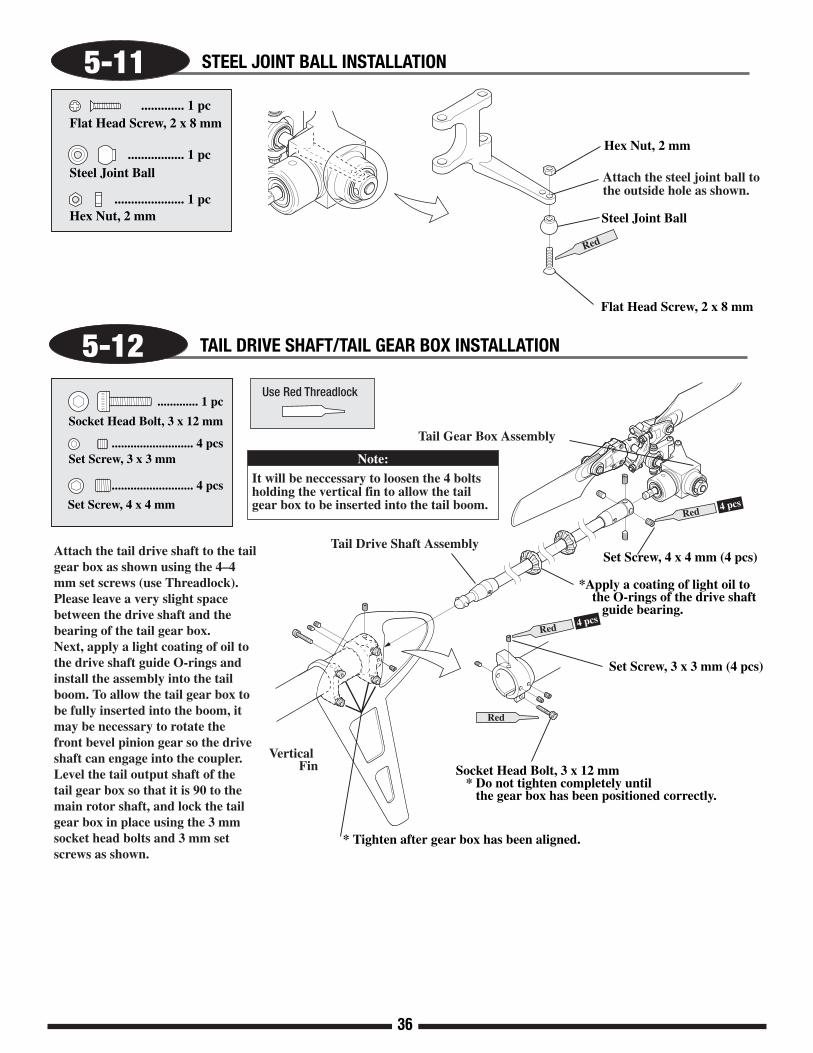
Flat Head Screw, 2 x 8 mm
Steel Joint Ball
Hex Nut, 2 mm
Red
Flat Head Screw, 2 x 8 mm
Steel Joint Ball
Hex Nut, 2 mm
Attach the steel joint ball to the outside hole as shown.
5-11 STEEL JOINT BALL INSTALLATION
5-12 TAIL DRIVE SHAFT/TAIL GEAR BOX INSTALLATION
Red 4 pcs
Set Screw, 4 x 4 mm (4 pcs)
*Apply a coating of light oil to the O-rings of the drive shaft guide bearing.
Red
Red 4 pcs
Set Screw, 3 x 3 mm (4 pcs)
Socket Head Bolt, 3 x 12 mm * Do not tighten completely until the gear box has been positioned correctly.
Set Screw, 4 x 4 mm
.......................... 4 pcs
.......................... 4 pcsSet Screw, 3 x 3 mm
Socket Head Bolt, 3 x 12 mm
............. 1 pcUse Red Threadlock
Tail Drive Shaft Assembly
Tail Gear Box Assembly
* Tighten after gear box has been aligned.
Attach the tail drive shaft to the tail gear box as shown using the 4–4 mm set screws (use Threadlock). Please leave a very slight space between the drive shaft and the bearing of the tail gear box. Next, apply a light coating of oil to the drive shaft guide O-rings and install the assembly into the tail boom. To allow the tail gear box to be fully inserted into the boom, it may be necessary to rotate the front bevel pinion gear so the drive shaft can engage into the coupler.Level the tail output shaft of the tail gear box so that it is 90 to the main rotor shaft, and lock the tail gear box in place using the 3 mm socket head bolts and 3 mm set screws as shown.
Vertical Fin
Note:
It will be neccessary to loosen the 4 bolts holding the vertical fin to allow the tail gear box to be inserted into the tail boom.

37
6-1 TAIL BELCRANK ATTACHMENT
Socket Head Bolt, 3 x 18 mm
Socket Head Bolt, 3 x 8 mm
..........1 pc
.............2 pcs
Step 4: Attach the aluminum mounting bracket to the right rear frame as shown using 2 3x8 mm Socket Head Bolts.
Flat Head Screw, 2 x 8 mm
..............2 pcs
Nylon Lock Nut, 3 mm
..................1 pc
Steel Joint Ball
...................2 pcs
Use Red Threadlock
Step 1: Insert the 2 flanged bearings and spacer into the belcrank.
Step 2: Attach 2 Steel Control Balls to the belcrank as shown using 2 2x8 mm Flat Head Screws. Note position/location of balls.
Flanged Bearing
Brass Spacer
Plastic Belcrank
Step 3: Attach the completed belcrank to the aluminum mounting bracket as shown.
Flat Head Screw, 2 x 8 mm (2 pcs)
Steel Joint Ball (2 pcs)
Plastic Belcrank
Aluminum Mounting Bracket
Socket Head Bolt, 3 x 8 mm
Red

38
6-2 UPPER SERVO/GYRO TRAY ATTACHMENT
Socket Head Bolt, 3 x 20 mm
Socket Head Bolt, 3 x 10 mm
..............................6 pcs
....................................4 pcs
Use Red Threadlock
Step 1: Attach the 2 48mm Cross Members to the gyro plate using the 4 3x6mm Flat Head Screws
Step 2: Attach the Carbon Upper Servo/Gyro Mounts to the gyro plate cross members using 4 3 x 10 mm Socket head Bolts.
Step 3: Attach the completed assembly to the main frame using the 6- 3x20mm Socket head bolts, 4- 6mm Hex Standoffs, and 2- 2.5mm Round spacers. Note that the 2.5mm Round Spacers fit between the Carbon plate and the Aluminum CCPM servo mount as shown.
Spacer, 2.5 mm
Cross Member, 32 mm
...........3 pcs
..........................................2 pcs
Special Cross Member, 48 mm
...2 pcs
Flat Head Bolt, 3 x 6 mm
...................................... 4 pcs
.....................................4 pcs
Hex Standoff, 6 mm
Special Cross Member, 48 mm (2 pcs)
Carbon Upper Servo/Gyro Mounts (2 pcs)
Flat Head Bolt,3 x 6 mm (4 pcs)
Carbon Gyro Plate
Socket Head Bolt, 3 x 10 mm (4 pcs)
Aluminum CCPM Servo Mount (1 pc)
Round Spacer, 2.5 mm (4 pcs)
Socket Head Bolt, 3 x 20 mm (6 pcs)
Hex Standoff, 6 mm (2 pcs)
Hex Standoff, 6 mm (2 pcs)
Cross Member 32 mm (3 pcs)

39
6-3 SERVO/SWITCH HARNESS INSTALLATION
................20 pcs
Self Tapping Screw, 2.6 x 12 mm
...............................20 pcs
...........................8 pcs
Flat Washer, 2.6 mm
CA Stopper Ring, 3.5 mm
Type-B Servo Mounting Plate
....................10 pcs
.............2 pcs
Self Tapping Screw, 2.6 x 15 mm
CA Stopper Ring, 3.5 mm Type-B Servo Mounting Plate
* Note correct servo output shaft orientation during installation.
Attach as shown.
Type-B Servo Mounting Plate (10 pcs)
Self Tapping Screw, 2.6 x 12 mm (10 pcs)
Self Tapping Screw, 2.6 x 15 mm (2 pcs)*This portion only. (without washer)
Flat Washer, 2.6 mm (10 pcs)
Collective Servo(Ch6)
Elevator Servo(Ch3)
Aileron Servo(Ch2)
Note output shaft direction.
A
A
B
C
C
*
Self TappingScrew, 2.6 x 12 mm (8 pcs)
Switch DampenerRubber (2 pcs)
Switch Harness
Screws Suppliedwith Switch
Flat Washer, 2.6 mm (8 pcs)
Switch
Switch Plate
Dampener Rubber (2 pcs)
Off
On
Rudder Servo
ThrottleServo
TEAM TIP: When installing theswitch harness, position it so that "Up" is off and "Down" is the on position. This will prevent the switch from accidentally being turned off in a hard landing or auto.
B
40
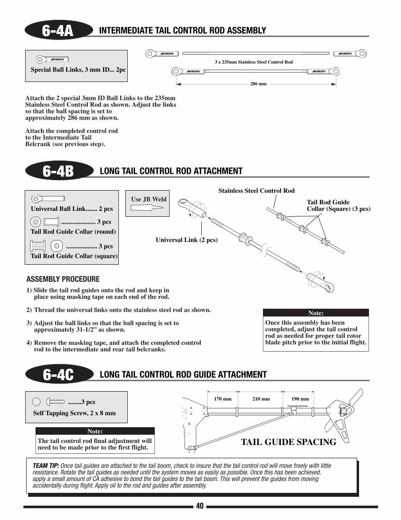
Special Ball Links, 3 mm ID... 2pc3 x 235mm Stainless Steel Control Rod
Attach the 2 special 3mm ID Ball Links to the 235mm Stainless Steel Control Rod as shown. Adjust the links so that the ball spacing is set to approximately 286 mm as shown.
Attach the completed control rod to the Intermediate Tail Belcrank (see previous step).
6-4A INTERMEDIATE TAIL CONTROL ROD ASSEMBLY
Note:
Once this assembly has been completed, adjust the tail controlrod as needed for proper tail rotor blade pitch prior to the initial flight.
6-4B LONG TAIL CONTROL ROD ATTACHMENT
6-4C LONG TAIL CONTROL ROD GUIDE ATTACHMENT
TEAM TIP: Once tail guides are attached to the tail boom, check to insure that the tail control rod will move freely with little resistance. Rotate the tail guides as needed until the system moves as easily as possible. Once this has been achieved, apply a small amount of CA adhesive to bond the tail guides to the tail boom. This will prevent the guides from moving accidentally during flight. Apply oil to the rod and guides after assembly.
Note:
The tail control rod final adjustment will need to be made prior to the first flight.
ASSEMBLY PROCEDURE1) Slide the tail rod guides onto the rod and keep in place using masking tape on each end of the rod.
2) Thread the universal links onto the stainless steel rod as shown.
3) Adjust the ball links so that the ball spacing is set to approximately 31-1/2” as shown.
4) Remove the masking tape, and attach the completed control rod to the intermediate and rear tail belcranks.
170 mm 210 mm 190 mm
TAIL GUIDE SPACING
..................... 3 pcs
Tail Rod Guide Collar (round)
................... 3 pcs
Tail Rod Guide Collar (square)
Use JB Weld
Universal Ball Link....... 2 pcsTail Rod Guide Collar (Square) (3 pcs)
Stainless Steel Control Rod
Universal Link (2 pcs)
........3 pcs
Self Tapping Screw, 2 x 8 mm
286 mm

41
6-5 GYRO/RECEIVER/BATTERY INSTALLATION
Be certain when installing the gyro unit to the front radio bed that it does not come in contact with the frame of the helicopter, etc. Also make sure that the front radio bed is free from oil and debris. Clean with rubbing alcohol if necessary to insure proper adhesion.
Note:
Wrap the receiver/gyro amplifier in sponge or foam rubber to protect from vibration.
Gyro Amplifier
Sponge/Foam Rubber
Gyro UnitReceiver
Double-Sided Servo Tapeor Velcro
Double-Sided Servo Tapeor Velcro
Ni-Cd Rx Battery Pack1800mAhminimum
Double-sided servo tape and sponge/foam rubber are not included in this kit.
Note:

42
The following preparations are suggested for use with JR® radio systems. However, these procedures are applicable to most other brand radio systems. These suggested adjustments are necessary to insure correct installation and attachment of the control linkages and servo horns.
TRANSMITTER PREPARATION
RECEIVER FLIGHT PACK PREPARATION
SERVO HORN INSTALLATION SUGGESTIONS
1. Set all trim levers, knobs, and switches to the neutral or zero positions.
2. Turn the transmitter power switch to the On position.3. Reset all functions and input values of your computer
radio system to the factory preset position.
4. Move the throttle/collective control stick to the center or half stick position. Next slide the throttle trim lever to the full low position.
1. With the transmitter still on, slide the receiver switch to its On position. All servos should move to the neutral or center position.
2. Check that all servos operate with the appropriate control stick.
3. Rest the throttle stick to the center position, making sure the throttle trim is still at low.
4. Turn off the receiver switch first, followed by the transmitter.
For proper operation, it’s important that the servo horns arepositioned on the servos in the “exact” neutral position. Althoughmost computer radio systems offer a sub-trim feature, it issuggested that the servo horns be manipulated on the servos toachieve the “exact” neutral settings.
Since the servo output spline on a JR system has an odd number of teeth (21), it’s possible to reposition the servo arm on the servo at 90° intervals to achieve the proper neutral attachment of the servo horn.
Once the correct arm of the servo horn has been established, it’s suggested that the remaining unused arms be removed from the servo horn as shown in the installation diagrams in thefollowing section.
It will also be necessary to enlarge the appropriate hole in the servohorn slightly to allow correct installation of the steel control balls tothe servo horn.
RADIO SYSTEM PREPARATION

120/140 3-SERVO CCPM SWASHPLATE MIXING
The JR® 120°/140° CCPM or Cyclic/Collective Pitch Mixing system offers the user a control system that can accomplish thesame control inputs as a one servo standard system, but with increased precision and reduced complexity.
As with the one servo system, the JR CCPM system utilizes three servos for the three main controls: aileron (roll),elevator(pitch), and collective. The CCPM lower swashplate ring is designed with only three control balls, spaced at 120° or140° from each other, hence the 120°/140° CCPM designation. Although the control balls are not at 90° as in the standardsystem, the aileron (roll) axis is still parallel to the main mechanics of the helicopter, and the elevator (pitch) axis still functionsat 90° to the mechanics as does the one servo system. Please refer to the diagram below for clarification.
The main difference in the way that these two systems operate is that unlike the one servo system where the three servoswork completely independent from each other, the CCPM systems work as a team to achieve the same control inputs. Forexample, if an aileron (roll) input is given, two servos work together to move the swashplate left and right. If an elevator (pitch)input is given, all three servos work together to move the swashplate fore and aft. For collective, it’s also the strength of threeservos that will move the swashplate up and down the main rotor shaft. With two or three servos working at the same timeduring any given control input, servo torque is maximized and servo centering is also increased. In addition to these benefits,CCPM achieves these control responses without the need for complex mechanical mixing systems that require many morecontrol rods and parts to set up.
This amazing CCPM control is achieved through special CCPM swashplate mixing that is preprogrammed into many oftoday’s popular radio systems. Since the 120° and 140° CCPM function is preprogrammed, CCPM is no more complicated to setup than a conventional one servo standard system. When you factor in the reduced parts count and easy programming, CCPM isactually easier to set up and operate than many conventional systems.
For JR radio owners, please refer to the radio information contained at the front of this manual or on the following pages todetermine if your radio system has the CCPM function. For other brands of radio systems, please contact the radio manufacturerfor CCPM information. Please note that it is not possible to program a non-CCPM radio system for CCPM operation.
43
UNDERSTANDING CCPM CONTROL SYSTEMS
Elevator Axis140°
JR 120°/140° 3 Servo CCPM Control System
Aileron Axis
Pitch Axis
Elevator Axis
Aileron Axis

44
The JR 120°/140° three servo CCPM relies on the radio’sspecial CCPM swashplate mixing, rather than a conventionalmechanical mixer that is utilized to achieve the same results.The radio’s 120° or 140° 3-servo CCPM function auto-matically mixes the three servos to provide the correct mixinginputs for aileron (roll), elevator (pitch), and collective. Thefollowing is an example of how each control input affects theservo’s movement.
1. COLLECTIVEWhen a collective pitch input is given, all three servos (A, B, and C) move together in the same direction, at equalamounts, to raise and lower the swashplate while keeping theswashplate level. During this function, all three servos travelat the same value (100%) so that the swashplate can remainlevel during the increase and decrease in pitch. As mentioned,this mixing of the three servos is achieved through the radio’sCCPM program.
2. ELEVATOR (PITCH)When an elevator input is given, all three servos must move to tilt the swashplate fore and aft, but their directions vary.The two front servos (B and C) move together in the samedirection, while the top servo (A) moves in the oppositedirection. For example, when a down elevator (forward cyclic)command is given, the two front servos (B and C) will moverearward, while the top servo (A) moves forward so that theswashplate will tilt forward. During this function with 120°CCPM, the top servo (A) travels at 100%, while the two frontservos (B and C) travel at 50% (1/2 the travel value) of the topservo. This difference in travel is necessary due to the fact thatthe position of the 120 CCPM rear control ball is two timesthe distance of the two front control ball position as measuredfrom the center of the swashplate. With 140° CCPM selected,all three servos travel at 100%, eliminating elevator trimchanges during quick collective inputs. This mixing of thethree servos is also achieved through the 140° CCPM programonly found in JR 10X systems.
3. AILERON (ROLL) When an aileron (roll) input is given, the two front servos (B and C) travel in opposite directions, while the top servo (A)remains motionless. For example, when a right aileron (roll)command is given, the left front servo (C) will move forward,while the right front servo (B) will move backward to tilt theswashplate to the right. As mentioned, the top servo (A) willremain motionless. The travel value for each of the two rearservos is 100%.
HOW 120/140 CCPM WORKS
Collective Movement1
A
BC
Elevator Movement2
Aileron Movement3
A
BC
45
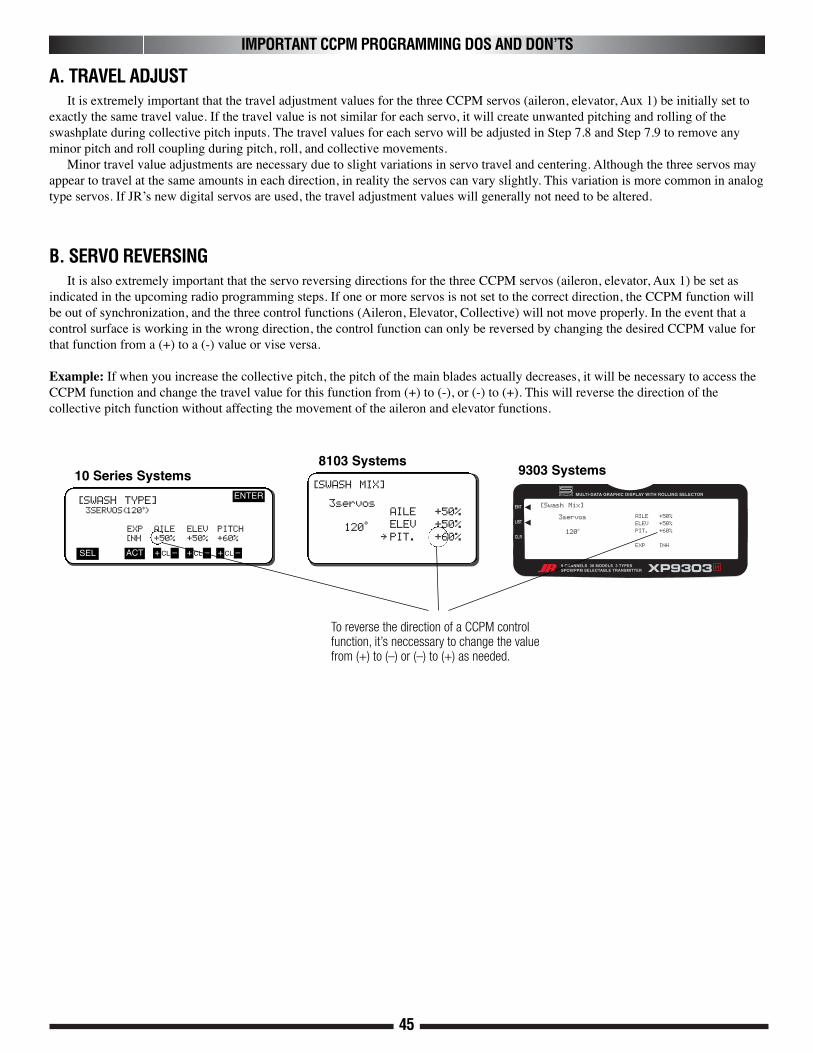
IMPORTANT CCPM PROGRAMMING DOS AND DON’TS
It is extremely important that the travel adjustment values for the three CCPM servos (aileron, elevator, Aux 1) be initially set toexactly the same travel value. If the travel value is not similar for each servo, it will create unwanted pitching and rolling of theswashplate during collective pitch inputs. The travel values for each servo will be adjusted in Step 7.8 and Step 7.9 to remove anyminor pitch and roll coupling during pitch, roll, and collective movements.
Minor travel value adjustments are necessary due to slight variations in servo travel and centering. Although the three servos mayappear to travel at the same amounts in each direction, in reality the servos can vary slightly. This variation is more common in analogtype servos. If JR’s new digital servos are used, the travel adjustment values will generally not need to be altered.
A. TRAVEL ADJUST
It is also extremely important that the servo reversing directions for the three CCPM servos (aileron, elevator, Aux 1) be set asindicated in the upcoming radio programming steps. If one or more servos is not set to the correct direction, the CCPM function willbe out of synchronization, and the three control functions (Aileron, Elevator, Collective) will not move properly. In the event that acontrol surface is working in the wrong direction, the control function can only be reversed by changing the desired CCPM value forthat function from a (+) to a (-) value or vise versa.
Example: If when you increase the collective pitch, the pitch of the main blades actually decreases, it will be necessary to access theCCPM function and change the travel value for this function from (+) to (-), or (-) to (+). This will reverse the direction of thecollective pitch function without affecting the movement of the aileron and elevator functions.
B. SERVO REVERSING
[SWASH TYPE]3SERVOS(120•)
EXP AILE ELEV PITCH
[NH +50% +50% +60%
ENTER
SEL ACT + –CL + –CL + –CL
To reverse the direction of a CCPM controlfunction, it’s neccessary to change the valuefrom (+) to (–) or (–) to (+) as needed.
10 Series Systems[SWASH MIX]
3servos
120•
AILE +50%
ELEV +50%
∞ PIT. +60%
8103 Systems
[Swash Mix]
3servos
120o
AILE +50%
ELEV +50%
PIT. +60%
EXP INH
9303 Systems

46
9
(Right) (PITCH)
(Right) (RUDDER)
(Right) (THROTTLE)
(Front) (ELEVATOR)
(Left) (AILERON)
The JR® 120°/140° CCPM system requires the use of three servos to operate, aileron, elevator, and Aux 1(Pitch). The labeling ofthese servos can become quite confusing because with the CCPM function; the three servos no longer work independently, but ratheras a team, and their functions are now combined. For this reason, we will refer to the three servos in the following manner:
Elevator Servo: We will refer to this servo as the “Top” servo. The channel number for this servo when using a JR radio is CH3.Aileron Servo: We will refer to this servo as the “Right Front” servo. The channel number for this servo when using a JR radio is CH2.Aux 1 (Pitch) Servo: We will refer to this servo as the “Left Front” servo. The channel number for this servo when using a JR radio is CH6.
Please refer to the CCPM connections chart below for clarification. For non-JR radios, please consult your radio instructions forproper connection.
C. CCPM SERVO CONNECTIONS
IMPORTANT CCPM PROGRAMMING DOS AND DON’TS (CONTINUED)
G500T GYRO (OPTIONAL)(JRPG500T)
C
A
B
C
A
B

47
CCPM SOFTWARE ACTIVATION AND INITIAL ADJUSTMENT
RADIO SYSTEM REQUIREMENTS (NOT INCLUDED):6-channel or greater R/C helicopter system with 120° or 140° CCPM function
10X120° or 140° CCPM
XP8103D.T.120° CCPM Only
CCPM-Ready JR Radio SystemsMost current JR heli radio systems (XP662, XP8103w/digital trims, XP9303, 10X, as well as older 10series systems) are equipped with 120° CCPMelectronics for use with JR CCPM machines. Radiosyou may be flying now, like the X347, X388S, XP783,and XP8103*, have 120° CCPM capability built in butrequire activation by the Horizon Service Department.Please call (217) 355-9511 for details.
*Please note that many XP8103 systems have the CCPM function alreadyactivated. Please check with the Horizon Service Center for details.
Current Radio SystemsJRP1656**PCM 10X, 120° & 140° CCPMJRP8622**XP8103FM, 120° CCPMJRP8653**XP8103PCM, 120° CCPMJRP9252** XP9303 PCM 120/140 CCPMJRP6822**XP662 FM,120° CCPMJR G500T Gyro or equivalent
XP9303120° or 140° CCPM

48
The following activation and setup procedure should be used for all JR 9303 systems.
Prior to activating the CCPM function, it is first suggested that the data reset function be performed to reset the desired modelnumber to be used back to the factory default settings.
Caution: Prior to performing the data reset function, it will be necessary to select the desired model number to be used.
A) Model Select/Data ResetPress the ENT key while turning the power switch on to enter the system mode. Next, move the cursor to the MODEL SELfunction. Press the roll selector to enter the model select function. Select the desired model number to be used, then press theroll selector. Next, move the roll selector to highlight LST, and press. Move the roll selector to highlight MDL RESET, thenpress. Press the CLEAR key, then press YES to reset the data of the current model selected.
B) CCPM ActivationMove the roll selector to highlight the SWASH TYP function, then press to access the swashplate type function.Press the roll selector to access the variations of CCPM mixing, then move the roll selector to select the desired CCPM type(120 or 140). Move the roll selector to highlight LST to exit the system mode.
CCPM SOFTWARE ACTIVATION AND INITIAL ADJUSTMENT (CONTINUED)
1. JR XP9303 SYSTEMS: PROGRAM INPUT
INFO-DISP
Model SEL
MDL Name
Type SEL
MDL Reset
MODULAT.
TRANSFER
TRIM STEP
Devic. SEL
SWASH TYP
[SYSTEM M.] [MDL R eset]
LST
NO
YES
MODEL 3 HELI SPCM
Are you sure? Y/N
[Swash Typ]
1servo
NORM
[SWASH TYPE]
120
6ch 2ch
3ch
3servos

49
C) CCPM SettingsTurn the power switch on, then press the ENT key to enter the function mode. Move the roll selector to highlight theSWASH MIX function, then press P. Once this has been completed, it will be necessary to change the value of theaileron, elevator, and pitch functions from the factory default setting using the + and - keys.
D) Servo ReversingMove the roll selector and highlight “Rev. Sw.” (Servo Reversing) appears on the screen, then press. Next, reverse channels 3, 4, and 6 by moving the Roll selector, and pressing as needed to change from NORM to REV.
E) Travel AdjustmentMove the roll selector and highlight “TRVL. ADJ.” (travel adjust) appears on the screen, then press. Adjust the values asshown by moving the roll selector to highlight the desired channel, while using the control stick to select up/down, orleft/right values to be adjusted. Please note that the required travel values will vary based on the type of servo selected.
Note: The travel values shown for the rudder function are for use with solid state and Ring Sensor type gyros, like the JR G500Tor G7000T type gyros.
CCPM SOFTWARE ACTIVATION AND INITIAL ADJUSTMENT (CONTINUED)
Digital Servos/Super Servos Standard Servos
REV NORM
THR
AIL
ELE
RUD
GER
PIT
AUX1
AUX2
[Swash Mix]
3servos
120o
AILE +50%
ELEV +50%
PIT. +60%
EXP INH
[REV SW.]
THR CH2 CH3 RUD GER CH6 --- AX3 AX4
REV.
NORM
[TRVL ADJ.]
THRO H100% L100% GEAR +
AILE L115% R115% PIT.
ELEV D115% U115% AUX2
RUDD L150% R150% AUX3
AUX4
+100% -100%
H115% L115%
+100% -100%
+100% -100%
+100% -100%
[TRVL ADJ.]
THRO H100% L100% GEAR +
AILE L100% R100% PIT.
ELEV D100% U100% AUX2
RUDD L150% R150% AUX3
AUX4
+100% -100%
H100% L100%
+100% -100%
+100% -100%
+100% -100%

50
The following activation and setup procedure should be used for all JR PCM10, 10S, 10SX, 10SxII, and 10X systems.
Prior to activating the CCPM function, it is first suggested that a data reset function be performed to reset the desired modelnumber to be used back to the factory default settings.
Caution: Prior to performing the data reset function, it will be necessary to select the desired model number to be used. Access themodel select function (code 84) and select the desired model to be used.
A) Data ResetAccess the data reset function (code 28) once the correct model number has been established. Next, press the Clear key to reset the current model. Press the Enter key to exit the data reset function.
B) CCPM ActivationAccess the swash type function (code 65). Next, press the SEL key until “3 servos (120°)” appears on the screen. For 10X owners, press the SEL key until “3 servos (140°)” appears on the screen. 140 CCPM is only found in the JR 10X radio system and was specifically designed for use with the Vibe 90 3D.Once this is complete, it will be necessary to change the value of the aileron,elevator, and pitch function from the factory default settings using the + and - keys below the pitch value. Press Enter to exit the swash type function.
C) Servo ReversingAccess the servo reversing function (code 11). Next, reverse channels 1, 2, and 4 by pressing the desired channel number. The screen should appear as shown.Press Enter to exit the servo reversing function.
D) Travel AdjustAccess the travel adjust function (code 12) and adjust the servo travel values as shown. Please note that the required travelvalues will vary based on the type of servo selected. Press Enter to exit the travel adjust function.
Note: The travel values shown for the rudder function are for use with solid state or Ring Sensor type gyros, like the JRG500T, or G7000T type gyros. If a conventional mechanical type gyro is used (JR 120, 130 etc.), then the travel valueof the rudder channel will need to be reduced to approximately 100%.
CCPM SOFTWARE ACTIVATION AND INITIAL ADJUSTMENT (CONTINUED)
2. JR 10 SERIES SYSTEMS: MANUAL PROGRAM INPUT
SETUP PROCEDURE
[DATA RESET]
MODEL 1 SPCM
CLEAR ENTER
[CLEAR]
[SWASH TYPE]3SERVOS(120•)
FXP AILE ELEV PITCH
[NH +50% +50% +60%
ENTER
SEL ACT + –CL + –CL + –CL
[REVERSE SW] REVERSE
NORMAL
ENTER
1 2 3 4 5 6 7 8 9 10
[TRAVEL ADJUST]
THRO AILE ELEV RUDD
H100% L115% D115% L150%
L100% R115% U115% R150%
PAGE
+ –CL + –CL + –CL + –CL
[TRAVELADJUST]
PITCH
+115%
-115%
+ –CL + –CL
[TRAVEL ADJUST]
THRO AILE ELEV RUDD
H100% L100% D100% L150%
L100% R100% U100% R150%
PAGE
+ –CL + –CL + –CL + –CL
[TRAVEL ADJUST]
PITCH
+100%
-100%
+ –CL + –CL + –CL
Select 3 Servos(120°)
digital servos/super servos Standard servos

51
7-1 PREPARATION AND INSTALLATION OF SERVO HORNS
............. 6 pcs
................. 6 pcs
..................... 6 pcs
Flat Head Screw, 2 x 8 mm
Steel Joint Ball
Hex Nut, 2 mm
Cut*See note
JR Large HD Servo Horn
27 mm
Front sideof horn
Back side of horn
Flat Head Screw2 x 8 mm(6 pcs)
Steel Joint Ball (6 pcs)
Hex Nut, 2 mm (6 pcs)
Test fit the servo horns to achieve the correct position as shown. Servo horn positions can be fine tuned using sub trim. Please refer to Section 7-2.
Red
Use Red Threadlock
JR HD Servo Wheels or equivalent will be required for this step (JRPA216, not included)
Before trimming the servo horns as shown, it is first suggested that these horns be test fit to the servo to achieve the correct positioning. JR servos utilize a 21 spline output shaft, which allows the position of the servo arm to be varied when rotated at 180-degree intervals. To test fit the servo horns, turn the radio system on, and set the collective stick to the center position. Next, test fit the servo arms at 180-degree intervals to find the direction that will allow the horn to be positioned as close to the vertical position (90 degrees from the servo case) as possible as shown in the diagram. This will reduce the amount of sub trim needed to bring the servo horns to the exact 90-degree position as shown. Once the position for each horn has been established, mark the servo arms for trimming, while also noting the servo that they have been fitted to (A, B, or C). Trim the servo horns as shown and attach the steel control balls in the desired hole locations. Reattach the servo horns to the servos, remembering to secure the horns to the servos using the servo horn screw. Final sub trimming of the servos will be performed in the proceeding Section 7-2.
Note:

52
1. XP9303 SYSTEMS
1) With the radio power switch on, press the ENT key to enter the function mode.2) Move the roll selector until until “Sub Trim” appears on the screen, then press.3) Adjust the left (CH-2), right (CH-6), and top (CH-3) servos as needed until the servo arm is exactly parallel
to the servo when the collective stick is in the center position. 4) Move the roll selector to LST to exit the Sub Trim function.
2. XP8103 SYSTEMS1) With the radio power switch on, press the Up and Down keys simultaneously to enter the function mode.2) Press the Up key until “Sub Trim” appears on the screen.3) Adjust the left (aileron), right (Aux 1), and top (elevator) servos as needed until the servo arm is exactly
parallel to the servo when the collective stick is in the center position. It will be necessary to press the SELkey once to access the right servo (Aux 1) sub-trim.
4) Press the Up and Down keys simultaneously to exit the function mode.
[Sub Trim]
£THRO ∞AILE
0 0
ELEV RUDD
0 0
[Sub Trim]
£GEAR ∞PIT.
0 0
AUX2 AUX3
0 0
Increase or decrease the value to centerthe front servo.
Increase ordecrease the valueto center the rightservo.
Increase or decreasethe value to centerthe left servo. SEL
3. JR PCM10, 10S, 10SX, 10SXII, 10X SYSTEMS
1) Enter the sub-trim function (code 15).2) Adjust the left (aileron), right (Aux 1) and top (elevator) servos as needed until the servo arm is exactly
parallel to the servo when the collective stick is in the center position. It will be necessary to press the Pagebutton to access the right servo (Aux 1) sub-trim value.
3) Press Enter to exit the sub-trim function.
[SUB TRIM]
THRO AILE ELEV RUDD GEAR
0 0 0 0 0
ENTERPAGE
+ –CL + –CL + –CL + –CL + –CL
Press Page to accessthe second screen.
Increase or decreasethe value to centerthe left servo.
Increase or decreasethe value to centerthe front servo.
[SUB TRIM]
PIT. AUX2 AUX3 AUX4 AUX5
0 0 0 0 0
ENTERPAGE
+ –CL + –CL + –CL + –CL + –CL
Increase or decrease the valueto center the right servo.
It may be necessary to make minor servo centering adjustments with the use of the sub-trim function toachieve the desired servo arm positions. Please refer to your particular radio’s section as listed below or consultyour radio instruction manual for more information.
7-2 CCPM SERVO CENTERING WITH THE SUB-TRIM FUNCTION
[Sub Trim]
THRO 0 GEAR 0
AILE 0 PIT. 0
ELEV 0 AUX2 0
RUDD 0 AUX3 0
AUX4 0

53
7-3 CONTROL ROD ASSEMBLY
140Standard Range (For 10X and XP9303 Systems only)
Control Rod, 2.3 x 70 mm
.........4 pcs
.........2 pcs
A
47.5 mm
Control Rod, 2.3 x 85 mmB
71 mm
120Standard Range (All Systems)
Control Rod, 2.3 x 85 mm
.........4 pcs
........2 pcsA
70.5 mm
Control Rod, 2.3 x 85 mmB
64.5 mm
All instructions are based on the use of the "standard range" CCPM setup. It is not recommended that the "wide range" setup be used, as it reduces servo resolution.
Note:

54
7-4 CCPM CONTROL ROD ATTACHMENT
Attach the control rods to the servo arms first. Next, test fit the rods to the T-lever balls to ensure that the rods are the correct length. If the rods are too long or too short, adjust each rod an equal amount until the control rods line up with each of the T-lever control balls.
Note:
Rod A (4 pcs)
Rod B (2 pcs)Use JR Ball Link Sizing Tool
55
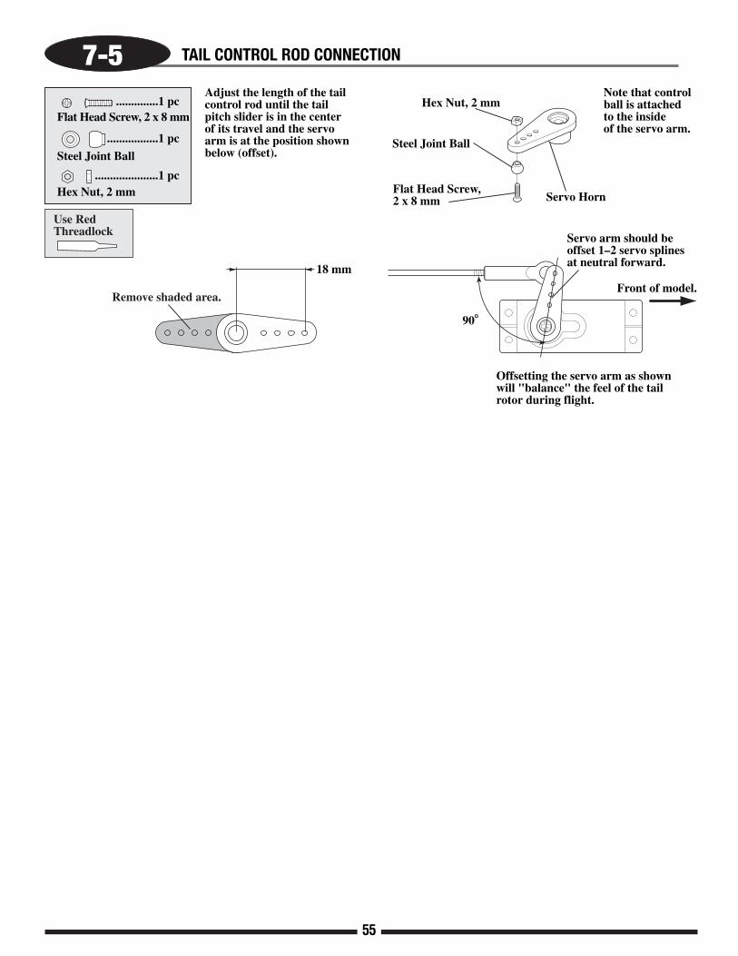
7-5 TAIL CONTROL ROD CONNECTION
..............1 pcFlat Head Screw, 2 x 8 mm
.................1 pc
Steel Joint Ball
.....................1 pcHex Nut, 2 mm Servo Horn
Flat Head Screw,2 x 8 mm
Steel Joint Ball
Hex Nut, 2 mm
90
18 mm
Use Red Threadlock Servo arm should be
offset 1–2 servo splines at neutral forward.
Front of model.
Adjust the length of the tail control rod until the tail pitch slider is in the center of its travel and the servo arm is at the position shown below (offset).
Note that control ball is attached to the inside of the servo arm.
Remove shaded area.
Offsetting the servo arm as shownwill "balance" the feel of the tailrotor during flight.

56
7-6A THROTTLE LINKAGE CONNECTION
..............1 pcFlat Head Screw, 2 x 8 mm
.................1 pc
Steel Joint Ball....................1 pc
Hex Nut, 2 mm
HighThrottle
LowThrottle
12.5
mm
Universal Link (2 pcs)Control Rod, 2.3 x 100 mm
82 mm (approximate)
Flat Head Screw, 2 x 8 mm
Steel Joint Ball
Hex Nut, 2 mmServo Horn
Attach thejoint ball tothe outsideof the servoarm.
Remove shaded area.
JR
*Option: For smooth operation, pre-size the ball links with the JR ball link sizing tool prior to attachment.

57
7-6B THROTTLE ARM/SERVO HORN POSITIONS
90
1/2 Stick (Throttle) Position(Throttle Barrel 1/2 open)
Low Stick (Throttle) Position(Throttle Barrel Fully Closed)
High Stick (Throttle) Position(Throttle Barrel Fully Open)
To achieve the correct position of the throttle/servo arm, it may be necessaryto re-position the throttle arm on the carburetor. It may also be necessary toadjust the length of the throttle linkage slightly to achieve full open andclosed positions of the carburetor.
Throttle Travel Adjustment (Initial Setup Only) 10 Series & Other SystemsIt is also possible to increase/reduce the travel of the throttle servo throughthe travel adjust function found in most computer radio systems. If thisfunction is used, make sure the values for the high and low positions remainequal (same value for high/low). If these values are not equal, it will create a differential, or uneven movement of the throttle, making rotor rpmadjustment and fine tuning more difficult.
Throttle Travel Adjustment (Full 3D Setup) with 8103 SystemsWhen setting up your throttle linkage for cyclic to throttle mixing withmany radio systems, it will be necessary to make any adjustment in thethrottle travel limits by mechanical means only. Move the control linkage inor out on the servo/throttle arms until the correct barrel travel is achieved.Please note that it is very important the ATV (travel volume) for both the high and low throttle setting remain at their maximum values (150%) toprevent over-travel and binding of the throttle linkage when cyclic to throttlemixing is used.
For initial cyclic to throttle mixing value information, please refer to the JR8103 and PCM10X series data sheets located on pages 73-77 of this manual.Please note that the values and mixing channels shown are universal to mostradio systems currently available.
Cyclic to Throttle Channel and Mixing Values (most systems)
*Numbers shown correspond with the correct JR channel numbers
Mixing Value AdjustmentPlease note that it will be necessary to determine if the desired mixingvalues need to be a + or - value based on servo direction, etc.
To verify the proper direction, move the control surface in each directionwhile watching the throttle arm. Throttle should increase each time a controlsurface input is given. Adjust the + or - value as necessary until the propermix is achieved.
Also check to confirm that the throttle travel is correct and is not causing abind in the control linkage after the cyclic mixing has been added.
*To avoid differential throttle travel, make certain both the throttle arm and the servo horn are positioned as shown in the above diagrams.
Mixing ValueLeft Right20 20
Up Down20 20
Mix #1 ChannelMaster SlaveAileron(2)* Throttle (1)*
Mix #2Master SlaveElevator(3)* Throttle (1)*
Note:

58
Check to insure the swashplate is level onthe fore/aft axis.
7-7 CHECKING THE SWASHPLATE FOR LEVEL
Check to insure that the swashplate is level on the left/right axis.
Reconfirmthat theelevatorarm is at 90.
Adjust the control rods as needed until the swashplate is level with all servos in their neutral (90) position.
Top Servo (A)Left Servo (C)
After the control linkages have been attached to the swashplate, it will be necessary to check the swashplate to insure that it is level. To do this, turn on the radio system and place the collective stick in the center position as before. Next, check to make sure that all trim levers and knobs are also in their center position. Check to insure that the servo arms are parallel to the servos as adjusted in the previous step. If the servos are not parallel, please refer to the sub-trim section 7-2 and readjust as necessary. Once it’s determined that the servo arms are parallel to the servos as required, it will now be necessary to check the swashplate to insure that it is also level or neutral in this position. It is suggested that the swashplate first be checked from the rear of the model to insure that it’s level from left to right. If the swashplate is not level as compared to the frame of the model, adjust either the left or right servo control rods as needed. To determine which rod needs adjustment, it may be helpful to view the swashplate from the left and right side view of the model to determine which side is high or low. Once this left to right adjustment is completed, it will now be necessary to check the fore/aft position of the swashplate to insure that it is also level on this axis. If the swashplate is not level in the fore/aft axis, it is suggested that the adjustment be made to the front servo control linkage as needed by slightly repositioning the elevator control arm on the elevator a-arm assembly, or adjusting both front servo control rods. If you are unsure as to which linkage needs adjustment or are having difficulty obtaining the correct adjustment, please check the length of each control rod to insure that it is adjusted to the correct length as outlined in Step 5-3.
If care was taken in the linkage assembly in Steps 4-6 and 7-3, little or no adjustment should be required in this step. Only minor adjustments should be made to the lengths of the control linkages at this time. Any major adjustments indicates either incorrect linkage lengths or incorrect servo arm positioning. If the control linkage lengths are altered from the recommended lengths more that one or two turns, this will have a great effect on the range and settings of the collective pitch in later steps.
Note:
90
90
90
90

59
It is very possible that the travel of each servo varies slightly, which can cause the swashplate to be tilted tothe left or right when the collective is moved to the extreme high and low pitch positions. This condition isgenerally more common when standard type servos are used. If JR® digital servos are used, the adjustmentrequired is generally very small, if any. These variations in travel can be corrected by altering the travel valueof each servo slightly through the travel adjustment function.
To check the pitch-to-aileron mixing, it will first be necessary to position the collective stick in the centerposition as in the previous steps. Next, move the collective stick from the center position to the high pitchposition while viewing the swashplate from the rear of the model as shown in the diagram below. Whilemoving the swashplate, look for any tendency for the swashplate to roll to the left or right as it reaches the highpitch position. Repeat this procedure several times to be sure that your observations are correct. If no rollingtendency is found, it will now be necessary to repeat this procedure from the center collective stick position tofull low pitch. If no rolling tendency is found, proceed to Step 7-9.
In our example, we have shown that the swashplate has been tilted to the right as the collective has beenincreased to full pitch. This would indicate that the left servo’s maximum travel is greater than the right servo’smaximum travel.
In this condition, we suggest that the travel value for the left servo be reduced slightly (5–10%). Repeatthe procedure above if the same condition occurs, but to a lesser degree. The travel value of the right servoshould be increased slightly and retested. In most cases, it will require only the adjustment of the left or rightservo to correct this situation.
View is shown from the rear of the model. Notice how theswashplate has tilted to the right as the collective has moved
from center to full high pitch position.
HighLow
Once this condition has been corrected, repeat this
procedure for the center tolow collective pitch position
and adjust as needed.
ELEV= Top ServoAUX1= Right Front ServoAILE= Left Front Servo
ABC
C B
7-8 PITCH-TO-AILERON MIXING ADJUSTMENT WITH TRAVEL ADJUST

60
The total travel of each servo can vary slightly, which can also cause the swashplate to be tilted fore and aftwhen the collective is moved to the extreme high and low pitch positions. This situation can also be corrected ifnecessary through the use of the travel adjustment function.
To check pitch-to-elevator mixing, it will first be necessary to position the collective stick in the center positionas in the previous steps. Next, move the collective stick from the center to the high pitch position while viewing theswashplate from the left side of the model. While moving the swashplate, look for any tendencies for the swashplateto tilt fore or aft as it reaches the high pitch positions. Repeat this procedure several times to be sure that yourobservations are correct. If no fore or aft tilting tendencies are found, it will now be necessary to repeat thisprocedure from the center collective stick position to full low pitch. If no tilting tendency is found, proceed to thenext step.
In our example, we have shown that the swashplate has tilted forward as the collective has been increased to fullhigh pitch. This would indicate that the top servo’s maximum travel is more than that of the two left/right servos.
In this condition, we suggest that the travel value for the top servo be decreased slightly (5–10%). Repeat theabove procedure and decrease the value as needed until the tilting tendency is eliminated. For information on thetravel adjustment function, please refer to your radio’s instruction manual for details. Once this condition has beencorrected, repeat this procedure for the center to low collective pitch position and adjust as needed.
Note: It is very important that during this step, only the travel value for the top servo (elevator) be adjusted tocorrect any pitch-to-elevator tendencies. If the travel value of the left or right servo changes, this willaffect the pitch-to-aileron tendencies corrected in the previous step. If you feel that readjustment of theleft and right servo travel is necessary, then it is suggested that the travel for each servo be increased ordecreased at the same amount and the pitch-to-aileron procedure be retested.
7-9 PITCH-TO-ELEVATOR MIXING ADJUSTMENT WITH TRAVEL ADJUST
View is shown from the left side of themodel. Notice how the swashplate hastilted forward as the collective hasmoved from the center to the full highpitch position.
High
Low
ELEV= Top ServoAUX1= Right Front ServoAILE= Left Front Servo
ABCCB
A

61
Now that the radio system is completely installed into the helicopter, it’snecessary to check and adjust the following:
1. Servo Direction (Servo Reversing)Check to insure that all servos have been set to the correct direction as shown in the Control Linkage Installation section.
2. Dual RatesIt’s suggested that for initial flights, the dual rate function values be set as follows:
0 Position (low rate) 100%1 Position (high rate) 100%
3. Exponential SettingsIt’s suggested that the exponential rate settings remain in the 25-30% value range until the initial test flights. After initial flights, adjust the exponential values to achieve the desired control feel.
4. Sub-Trim SettingsIt’s suggested that the correct neutral settings be achieved without the use of the Sub-Trim function, as this will affect the neutral position of the servos. Adjust the cyclic trim using the control rods until a neutral hover is achieved.
5. Pitch/Throttle Curve AdjustmentIt is very important the throttle and pitch curves are adjusted properly to achieve the best performance from your helicopter. When properly adjusted,the main rotor head rpm should remain consistent throughout all maneuvers and throttle stick positions. A constant rpm will also help to improve the effectiveness and accuracy of the tail rotor and gyro systems.
A) Pitch CurveIt will now be necessary to establish the maximum pitch
value required for your application prior to adjustment. Forexample, if you are a 3D pilot, then your maximum negativepitch will be -10, and your maximum positive pitch will be +11.The maximum pitch range that you will require will be 21° total.
The maximum pitch range mentioned above must beestablished through the use of the pitch travel value in the CCPMfunction. As mentioned previously, do not try to establish themaximum pitch curve values through adjustment of the traveladjustment function, as this will alter the pitch-to-aileron andpitch-to-elevator travel values established in Steps 7-8 and 7-9.Please refer to the CCPM activation section (page 46) forinformation on how to access the CCPM function.
Once the CCPM function has been activated, set themaximum positive pitch settings as mentioned above. Since theCCPM function does not allow for independent travel settings forpositive and negative pitch, it will be necessary to establish themaximum positive pitch, since this is generally the largest degreeof pitch in the pitch range. Once the maximum positive pitchrange is set, the maximum negative pitch range can be reduced asneeded through the pitch curve function.
Set the main rotor pitch gauge to the desired maximum pitchsetting, then increase or decrease the CCPM pitch travel (labeledPitch or Ch6) as needed until this pitch setting is achieved.
Once this procedure has been completed, the positive andnegative pitch settings for each flight mode can be adjustedthrough the radio’s pitch curve function. Please refer to yourradio’s instruction manual for more information.
FINAL SERVO ADJUSTMENT AND RADIO SETUP
0°
-9°
1°
Normal(Hover)
Stick Position
Low 1/4 1/2 3/4 High
Stick Position Stick Position
Flight Mode 13D Stunt 1
Autorotation(Throttle Hold)
Flight Mode 23D Stunt 2
(Duplicate of #1)
Pitch Curve Settings
Pitch Range+11.5°
0°
-9°-9°Low 1/4 1/2 3/4 High
Pitch Range+11°
0°
-9°Low 1/4 1/2 3/4 High
Pitch Range+11.5°
-9°
1°
2°
4°
3°
2°
3°
4°
Flight Application Low Pitch Hovering Pitch High PitchMode (Low Stick) (Half Stick) (High Stick)
N Hovering -10° +5° +10°I 3D Flight #1 -10° +5° +11°
*2 3D Flight #2 -10° +5° +11°H Autorotation -10° +5° +11.5°
Pitch Range Settings
[SWASHTYPE]3SERVOS(120•)
EXP AILE ELEV PITCH
+50 +50 +60
ENTER
SEL ACT + –CL + –CL + –CL
Increase or decreasethe value as needed.
Increase or decrease the value as needed.
[SWASH MIX]
3servos
120•
XP8103 System XP9303 System
PCM 10 Series
AILE +50%
ELEV +50%
∞ PIT. +60%
Note: Flight modes #1 and #2 are duplicated for safety.
Stick Position
0°
-9°-9°Low 1/4 1/2 3/4 High
Pitch Range+11°
1°
2°
4°
3°
1
[Swash Mix]
3servos
120o
AILE +50%
ELEV +50%
PIT. +60%
EXP INH
62
FINAL SERVO ADJUSTMENT AND RADIO SETUP (CONTINUED)
It will also be necessary to set the correct idle speed of the engine when thethrottle hold function is activated.
This idle value is located within the throttle hold function. This will allow theengine to remain at idle when practicing autorotations.
6. Gyro Gain Adjustment (All Gyros)Please refer to your Gyro’s instruction manual for proper gain settings.
Gyro DirectionIt will also be necessary to confirm the direction the gyro compensates when thebody of the helicopter is rotated.
To do this, turn the radio system on and suspend the helicopter by the main rotorhead. Next, move the rudder stick to the right and watch the direction that the tailrotor servo arm travels. Now while watching the tail rotor servo arm, rotate thebody of the helicopter counterclockwise. The servo arm should move in the samedirection as when the rudder stick was moved to the left.
If the arm moves in the opposite direction, reverse the gyro and re-test.
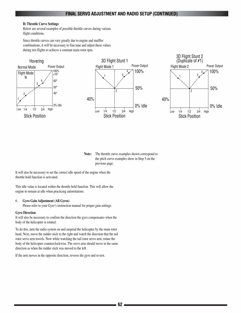
Note: The throttle curve examples shown correspond to the pitch curve examples show in Step 5 on the previous page.
40%
Hovering
100%
50%
0% Idle
Power Output3D Flight Stunt 1
Stick PositionStick Position
Flight Mode 1
B) Throttle Curve SettingsBelow are several examples of possible throttle curves during various flight conditions.
Since throttle curves can vary greatly due to engine and muffler combinations, it will be necessary to fine tune and adjust these values during test flights to achieve a constant main rotor rpm.
50°
40°
60°
0% Idle
Power Output100%+10°Flight Mode
N
Low 1/4 1/2 3/4 HighLow 1/4 1/2 3/4 High
40%
100%
50%
0% Idle
Power Output
3D Flight Stunt 2(Duplicate of #1)
Stick Position
Flight Mode 2
Low 1/4 1/2 3/4 High
Normal Mode
1
2
34
1
2
34
1
2
34

63
8-1 GROMMET ATTACHMENT
Rubber Grommets
.........4 (or 6) pcs
Rubber Grommets (4 pcs)
Insert rubber grommets as shown.

64
8-2 BODY ATTACHMENT & FINAL FITTING
Flat Washer, 3 mm
........................... 4 pcs
Socket Head Bolt 3 x 12 mm............ 4 pcs
Flat Washer, 3 mm (4 pcs)
Socket Head Bolt, 3 x 12 mm (4 pcs)
Check to insure the body does not come in contact with any portion of the main frame, muffler, servo, servo horns, etc. Trim for clearance if necessary.

65
DECAL PLACEMENT