Drive Beam Phase Measurements and Feedback at CTF3 Giulio Morpurgo.
27
Drive Beam Phase Measurements and Feedback at CTF3 Giulio Morpurgo
-
Upload
alan-gallagher -
Category
Documents
-
view
216 -
download
2
Transcript of Drive Beam Phase Measurements and Feedback at CTF3 Giulio Morpurgo.

Drive Beam Phase Measurements and Feedback at CTF3
Giulio Morpurgo

Outline of this presentation
• The “phase synchronization” problem at CLIC
• The test-stand (CTF3)– what do we want to do there– Some data from existing measurements

The problem:
The synchronization the CLIC beams
• Two couple of beams (DB1, MB1 and DB2, MB2)• Synchronize DB1 (x 24) with MB1• Synchronize DB2 (x 24) with MB2• Synchronize MB1 with MB2 (not treated here)

Why must the MB and the DB be synchronized ?
The Drive Beam carries the energy needed to accelerate the Main Beam.
This energy, in the form of a 12 GHz pulse, is transferred to the RF cavities of the Main Linac, which produce a 12 GHz accelerating field to be seen by the Main Beam bunches.
If this field has a wrong phase when the Main Beam sees it, the Main Beam will not be accelerated properly.

DB<->MB Synchronization points
drive beam accelerator
combiner rings
CR1CR2
delayloop
1 km
e+ injectore- injector
CLIC 3 TeV
e+ main linace- main linac
BC2BC2
BC1
e+ DRe- DR
booster linac
decelerator, 24 sectors of 868 m
IP1
BDS2.75 km
BDS2.75 km
47.9 km
CR2delayloop
drive beam accelerator
1 km
CR1
TAR=120m
TAR=120m
245m 245m
DB
MB
MB<->MBMain BeamDrive Beam
MB<->DB Synchronization
MB<->MB Synchronization
? ?

What happens at every “synchronization point”
• The Main Beam arrives, on its way to the end of the CLIC tunnel. Its “phase” relative to a precise and stable oscillator is measured.
• After some time, the Drive Beam train for this sector arrives. Its “phase” is also measured. The difference between the two phases is compared with a (predefined) “reference value”.
• The Drive Beam is deflected into the turn-around, where its path length is fine-tuned in accordance with the above phase measurements (RT phase feed-forward)
• The Drive Beam enters the deceleration sector, and start transferring its energy to the RF cavities
• Soon after, the Main Beam appears again, having travelled to the final turn-around and back, ready to be accelerated by the RF cavities

The famous MB <-> DB phase feed-forward in the tunnel
Using a (local) femto-timing system, measure delay ΔØreal between the two outgoing beams
DB turn-around
MB to IP
Out-going DB B
B’
D
D’
Sensitivity of δE measurement/correction? Intra-pulse corrections ?*Precision of the « phase » measurement *Stability of local timing
C
• At B&B’: compare ΔØ (MB<->DB)real with reference ΔØ (the difference is the “phase” error)• Also measure Drive Beam energy error δE (use A&B)• Compute correction (δE dependent) to “re-align” DB to MB using “C-D” chicane
• Use D&D’ to measure residual phase error MB/DB after feed-forward• Use B&C to measure time to cover the Drive Beam turn-around
Out-going MB
*see work by J.Sladen and A.Andersson, EPAC 2006, PAC 2007, CLIC-Note-734
Issues:
A MB turn-around
Decelerating DB

The MB-DB synchronization requirementThe max. acceptable “phase” error (generated by a wrong delay between the arrival times of the Drive Beam and the Main Beam) has been set at 0.2° at 12 GHz. (equivalent to a distance error of ~ 10 µm)
If the drive beam(s) and the main beam have a wrong relative “phase”, the main beam
– will not be accelerated properly, and – its size will be enlarged by the Beam Delivery System (reducing
luminosity)
A correlated (among the 24 synchronization points) phase error of 0.2 ° corresponds to a relative luminosity reduction of ~1%*
*D. Schulte, CLIC-Note-803

MB<->DB synchronization:What exactly has to be synchronized? (and measured)
• A train of the drive beam consists of 2904 bunches spaced by 83.3 picoseconds (2.5 cms)
• The bunches of the drive beam lose their energy in the PETS, and this energy produces the accelerating field for the main beam.
• Every bunch of the main beam is accelerated by the field– produced by n (~600) bunches* of the drive beam– (perturbed by the previous n/6 main beam bunches)
• The Main Beam bunches have to see a correct RF phase to be accelerated properly *For an RF cavities filling time of ~50 ns

What can be done at CTF3
• Measure the “phase stability” of the RF structures (pulse to pulse and within same pulse)
• Measure the phase stability of the accelerated Drive Beam
• Identify sources of instabilities and their effects• Measure the phase stability of the signal induced by
the Drive Beam in the 12 GHz structures of the TBTS• (second stage) Implement a prototype for the feed-
forward system.

• What we would like to achieve in 2010 and beyond
• Some data from the existing measurement system

A programme in two phases• Phase 1 (2010): use existing measurement systems (RF
measurements, Beam Current measurements etc.) – To get a first feeling about the orders of magnitude – To identify/correlate instability sources
• Phase 2 (end 2010 and beyond): build a more sophisticated system*, to reach the precision eventually required (0.2 ° at 12 GHz --> 0.05 ° at 3 GHz)– Dedicated acquisition system– Beam phase monitors– (Precise timing distribution, beam arrival time monitors ?)
* A lot of work in this direction has been done in the past at CTF3 by A. Andersson and J. Sladen

fully loadedacceleration
recombination x 2
phase-coding
bunch lengthcontrol
recombinationx 4
bunchcompression
two-beamacceleration
structures12 GHz
CTF3 as a test-stand
The CTF3 Linac: Phase measurements will be performed here

Structure of the CTF3 beam• At the Linac :
-”Pre-pulse header” (~100 bunches): used to stabilize RF power; dumped after linac. We have to discard its signal from our measurements.
- Pulse length 1.12 µs (~1680 bunches)- Bunch spacing 666 ps (20 cm)- One bunch every second 3GHz RF bucket; every 140ns (210
bunches) the occupancy parity is changed
• After recombination (delay loop + combining ring)- Pulse length 140 ns (12 GHz)- Bunch spacing 83.3 ps (2.5 cm)
It is also possible to have a shorter pulse length in the Linac, and to suppress the 140ns phase switching
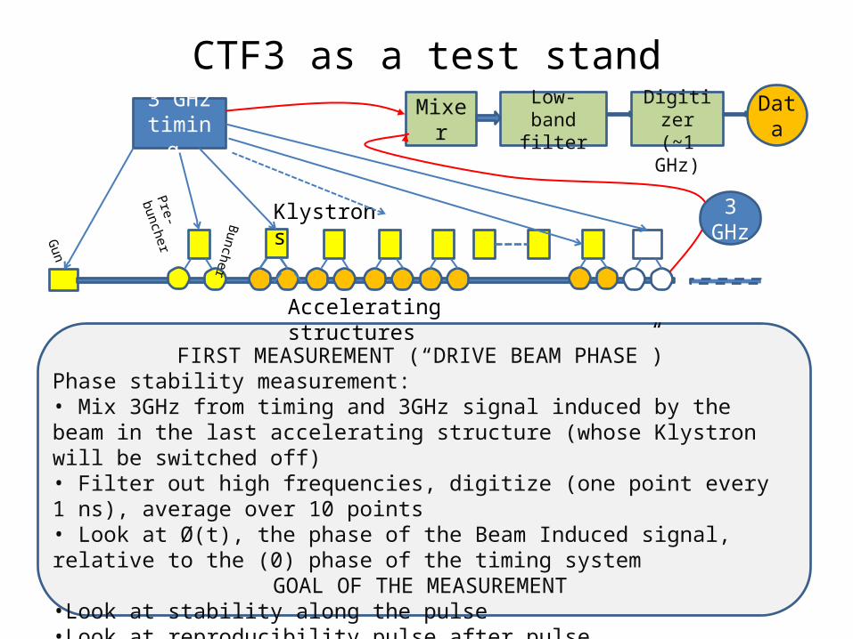
CTF3 as a test stand
Pre-buncher
Gun
Klystrons
3 GHz timing
FIRST MEASUREMENT (“DRIVE BEAM PHASE”)Phase stability measurement:• Mix 3GHz from timing and 3GHz signal induced by the beam in the last accelerating structure (whose Klystron will be switched off)• Filter out high frequencies, digitize (one point every 1 ns), average over 10 points• Look at Ø(t), the phase of the Beam Induced signal, relative to the (0) phase of the timing system
GOAL OF THE MEASUREMENT•Look at stability along the pulse•Look at reproducibility pulse after pulse
Buncher
Accelerating structures
Mixer Low-band filter
Digitizer (~1 GHz)
Data
3 GHz

Pre-buncher
Gun
Klystrons
3 GHz timing
MEASURE PHASES FROM ALL CAVITIES
• The goal of this measurement is to determine if phase instabilities in different cavities are correlated or not. This is important to predict the way the error will accumulate in the CLIC Drive Beam Linac. The tolerance for uncorrelated errors is more relaxed than the tolerance for correlated ones
buncher
Accelerating structures
Mixer Low-band filter
Digitizer (~1GHz) Data
Mixer Low-band filter
Digitizer (~1GHz) Data

Pre-buncher
Gun
Klystrons
3 GHz timing
INCLUDE BEAM CURRENT DATA FROM WALL CURRENT MONITORSMONITOR ALSO THE TEMPERATURE
• The goal is to study correlation between the phase measurements and the beam current, both inside a pulse, and pulse after pulse
• Also the temperature can have an effect which should be analyzedBuncher
Accelerating structures
Mixer Low-band filter
Digitizer (~1 GHz)
Data
Mixer Low-band filter
Digitizer (1 GHz)
Data
Wall current monitorsThey are capable of measuring the beam
current distribution inside the pulse

fully loadedacceleration
recombination x 2
phase-coding
bunch lengthcontrol
recombinationx 4
bunchcompression
two-beamacceleration
structures12 GHz
Future development: measure phase at the two beam test stand
It would also be interesting to make a phase measurement getting the signal from the two beam test area. (even if we know that no effort is done to maintain the phase stability)
Mixer Low-band filter
Digitizer (~1GHz) Data
MixerLow-band
filter Digitizer (~1GHz) Data

Other measurements (later)
• Phase feedback prototype– It would be nice to use the Combined Ring and the
Extraction Line as a Test Stand to implement a Phase / Beam Arrival Time feedback
• Timing distribution– The CTF3 complex should also be used to gain
experience with a “femto-second” timing system like the one needed for CLIC

fully loadedacceleration
phase-coding
two-beamacceleration
structures12 GHz
CTF3 as a test-stand for phase feed-forward
Possible installation of a RT phase feed-forward prototype
measure
correct
verify
Phase monitor
Global Timing

To conclude:Some data from existing measurements
( thanks to Alexey Dubrovskiy)
•Each dataset contains data acquired over ~200 consecutive pulses (1.2 seconds apart)
•The data from one individual pulse is an array of values acquired every 10 ns
•On each plot, all the 200 pulses are shown, in alternated colours, to give an idea of the pulse-to-pulse spread
•Two kinds of plots: - Absolute values- Difference from previous pulse

Data from existing measurements ( thanks to Alexey Dubrovskiy)
Amplitudes and amplitude jitters of
all RF structures, plus sum of all
structures

Phase jitters of all RF structures,
plus sum of jitters

An average RF structure

A good RF structure...
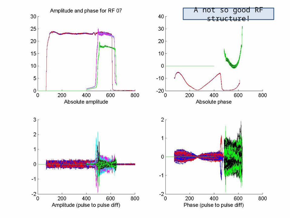
A not so good RF structure!

Last but not least...
I would like to thank in advance the many colleagues who will actively contribute to this activity!