Drivability of an Instrumented 2,440-mm Diameter Rammed Pipe
9
TM1-T4-04 Drivability of an Instrumented 2,440-mm Diameter Rammed Pipe Armin W. Stuedlein, PhD, PE, Oregon State University, Corvallis, OR Tadesse Meskele, PhD, GRI, Inc., Beaverton, OR ABSTRACT: Drivability analyses performed using the one-dimensional wave equation have been an accepted engineering practice for the installation of driven piles for over thirty-five years, due to the ability to accurately predict driving performance. Pipe ramming represents an analogous application to pile driving, yet drivability analyses are not yet common, despite the ability to predict the rate of driving and the driving stresses that are induced by the impact energy delivered by the pipe ramming hammer. This paper presents a case history of an instrumented, 2,440 mm diameter pipe driven through an active highway embankment using pipe ramming. The performance of the rammed pipe is described in terms of pipe-hammer energy transfer, ramming-induced stresses, and total, static and dynamic soil resistance. Drivability analyses calibrated using new pipe ramming-specific static soil resistance model and dynamic soil parameters generated using the results of several instrumented pipe rams are performed and compared to the observed field results. The comparison of observed and predicted driving performance indicates that drivability analyses can satisfactorily predict the penetration resistance and ramming- induced stresses and be used to plan pipe ramming installations. 1. INTRODUCTION Pipe ramming is an emerging trenchless technology alternative that is appropriate for relatively shallow to deep culvert, pipe, and casing installations. Because pipes fitted with appropriately designed cutting shoes produce little heave or settlement (Stuedlein and Meskele 2013), pipe ramming installations present a particularly attractive tool for state departments of transportation and other state or municipal agencies charged with mitigating risk to existing infrastructure when adding capacity or improvement to public works. Part of appropriate planning activities for a pipe ramming installation is to estimate the ability of a given hammer to install a given length and diameter of pipe without causing damage to the pipe or nearby infrastructure. Stuedlein and Meskele (2012, 2013) and Meskele (2013) present the results of a comprehensive research program aimed to improve the understanding of soil-pipe interaction that addresses pipe drivability, driving stresses, ground vibrations, and ground deformations. The basis for the research is a series of instrumented production pipe ramming installations and a full-scale field research experiment of pipes rammed through granular soils. Instrumented pipes included diameters ranging from 610 to 3,660 mm, and represent the range of commonly rammed pipe diameters. Existing analytical tools were successfully adapted for use in predicting pipe drivability and driving tresses when coupled with newly developed pipe-ramming specific soil resistance models. In order to illustrate the driving performance of a large diameter rammed pipe and the predictability thereof, this paper presents a case history of a 2,440 mm diameter instrumented pipe for which dynamic measurements were made during installation. The driving performance is described, including the magnitudes of hammer-pipe energy transfer, driving stresses, and the total (i.e., static and dynamic) soil resistance to ramming. Following the description of the methodology used to make estimates of pipe drivability, the driving stresses generated during the installation of the 2,440 mm diameter pipe is evaluated using the new pipe ramming-specific soil resistance models and is shown to be satisfactorily estimated, indicating the suitability of the selected approach for pipe ramming North American Society for Trenchless Technology (NASTT) NASTT’s 2014 No-Dig Show Orlando, Florida April 13-17, 2014 Paper TM1-T4-04 - 1
Transcript of Drivability of an Instrumented 2,440-mm Diameter Rammed Pipe
TM1-T4-04
Drivability of an Instrumented 2,440-mm Diameter Rammed Pipe Armin W. Stuedlein, PhD, PE, Oregon State University, Corvallis, OR Tadesse Meskele, PhD, GRI, Inc., Beaverton, OR ABSTRACT: Drivability analyses performed using the one-dimensional wave equation have been an accepted engineering practice for the installation of driven piles for over thirty-five years, due to the ability to accurately predict driving performance. Pipe ramming represents an analogous application to pile driving, yet drivability analyses are not yet common, despite the ability to predict the rate of driving and the driving stresses that are induced by the impact energy delivered by the pipe ramming hammer. This paper presents a case history of an instrumented, 2,440 mm diameter pipe driven through an active highway embankment using pipe ramming. The performance of the rammed pipe is described in terms of pipe-hammer energy transfer, ramming-induced stresses, and total, static and dynamic soil resistance. Drivability analyses calibrated using new pipe ramming-specific static soil resistance model and dynamic soil parameters generated using the results of several instrumented pipe rams are performed and compared to the observed field results. The comparison of observed and predicted driving performance indicates that drivability analyses can satisfactorily predict the penetration resistance and ramming-induced stresses and be used to plan pipe ramming installations. 1. INTRODUCTION Pipe ramming is an emerging trenchless technology alternative that is appropriate for relatively shallow to deep culvert, pipe, and casing installations. Because pipes fitted with appropriately designed cutting shoes produce little heave or settlement (Stuedlein and Meskele 2013), pipe ramming installations present a particularly attractive tool for state departments of transportation and other state or municipal agencies charged with mitigating risk to existing infrastructure when adding capacity or improvement to public works. Part of appropriate planning activities for a pipe ramming installation is to estimate the ability of a given hammer to install a given length and diameter of pipe without causing damage to the pipe or nearby infrastructure. Stuedlein and Meskele (2012, 2013) and Meskele (2013) present the results of a comprehensive research program aimed to improve the understanding of soil-pipe interaction that addresses pipe drivability, driving stresses, ground vibrations, and ground deformations. The basis for the research is a series of instrumented production pipe ramming installations and a full-scale field research experiment of pipes rammed through granular soils. Instrumented pipes included diameters ranging from 610 to 3,660 mm, and represent the range of commonly rammed pipe diameters. Existing analytical tools were successfully adapted for use in predicting pipe drivability and driving tresses when coupled with newly developed pipe-ramming specific soil resistance models. In order to illustrate the driving performance of a large diameter rammed pipe and the predictability thereof, this paper presents a case history of a 2,440 mm diameter instrumented pipe for which dynamic measurements were made during installation. The driving performance is described, including the magnitudes of hammer-pipe energy transfer, driving stresses, and the total (i.e., static and dynamic) soil resistance to ramming. Following the description of the methodology used to make estimates of pipe drivability, the driving stresses generated during the installation of the 2,440 mm diameter pipe is evaluated using the new pipe ramming-specific soil resistance models and is shown to be satisfactorily estimated, indicating the suitability of the selected approach for pipe ramming
North American Society for Trenchless Technology (NASTT) NASTT’s 2014 No-Dig Show
Orlando, Florida April 13-17, 2014
Paper TM1-T4-04 - 1

applications. Planners, engineers, and contractors are encouraged to adopt the analysis described herein in order to assist reduce the risk of failure with pipe ramming installations. 2. HIGHWAY 21 CULVERT REPLACEMENT PROJECT, GODERICH, ON. The Ministry of Transportation of Ontario (MTO) replaced the existing 2440 mm diameter corrugated metal pipe (CMP) culvert that transports Allan’s Creek under Highway 21, north of Goderich, Ontario, due to collapse of the existing culvert. The project called for installation of a new 2440 mm diameter steel culvert with 241 MPa yield strength, 25 mm wall thickness, and 39 m in length parallel to the failing CMP culvert. The project was completed in July 2010. Realignment of the culvert centerline was requested due to the existence of abandoned concrete abutments that were constructed in the early 1900s at the crossings. However, Canadian Department of Ocean and Fisheries did not allow the realignment and the installation was accomplished by driving (i.e., ramming) the new pipe through the abandoned concrete structures. Subsurface investigation of the project site conducted by Golder Associates included the four borings drilled through the highway embankment (Golder Associates 2010), shown in Figure 1 along with the profiles of the embankment along the centerline of the culvert. Two boreholes were drilled in the shoulders through the existing embankment to depths of 11.1 m (B 302 and B 303); the other two borings were drilled near the west and east ends of the culvert to depths of 4.3 m. The embankment consisted of variable fill material, ranging from loose to medium dense sandy silt, silty sand, some sand and gravel, and stiff to very stiff clayey silt (Golder Associates 2010). The groundwater ranged in depth between 0.6 m below grade at B 301 (not shown) and 6.7 m below the grade of the embankment (B302 and B 303), just above the pipe invert. As shown in Figure 1, the pipe penetrated largely granular soils.
Figure 1. Profile along the centerline of the culvert showing embankment cross-section and results of Standard Penetration Testing (after Golder Associates 2010). The installation of the new culvert was carried out in four stages with installation of three 12 m long pipe segments and one 2.5 m pipe segment. The installation began with the excavation of a launching pit that was prepared by the construction of a leveled crushed rock bedding layer. Steel tracks were placed on steel mats, in turn placed on the prepared ground surface to help guide the hammer-pipe system and maintain the required grade and alignment (Holcomb 2012). In the first stage of installation, the 12 m pipe segment was driven with a cutting shoe at the leading edge. The dimensions of the cutting shoe are provided in Figure 2a as described by Robinson (2012). The cutting shoe assisted in ramming through the four abandoned and buried concrete wing walls (Holcomb 2012). In the following three stages, the two 12 m and one 2.5 m pipe segments were driven, respectively, to cross the embankment. The impact driving was carried out with an 800 mm pneumatic Grundoram Apollo hammer with a rated energy of 40.5 kN-m (29.9 kip-ft) and blow rate of 180 blows per minute (bpm). The hammer was fitted to the rear end of the pipe with tapered ram cone and cotter segments that facilitated the connection and distribute the impact force of the hammer to the edge of the pipe casing. The pipe-ram cone-hammer system was held in place by tensioned chains hooked to eye pads welded on each segment of the pipe, as shown in Figure 2b.
Paper TM1-T4-04 - 2

The new culvert installation was instrumented to monitor overall performance of the steel casing during installation (Figure 2b). The pile driving analyzer (PDA) system, described in detail by Meskele and Stuedlein (2011) and Stuedlein and Meskele (2012), was hooked to twin accelerometers and stain gauges on each side of the pipe springline to measure the dynamic response of the pipe. These strain gauges and piezoelectric accelerometers are usually mounted approximately at 2D from the rear end of the pipe segment, however, they were mounted approximately at 1D (2.4 m) due to the large diameter of the pipe and the relatively short installation segment lengths so as to maximize the length of the penetration record. The dynamic stress wave measurements were only observed for the second and third stage of the 12 m pipe segments installation, as described subsequently.
50 mm
75 mmBand length 915 mm
Band gap 255 mm
(a)
Figure 2. Details of the 2,440 mm diameter pipe: (a) cutting shoe geometry, and (b) instrumentation, including high-frequency strain gages and accelerometers, located one diameter from the rear of the pipe. 3. DRIVING PERFORMANCE OF THE PIPE RAMMING INSTALLATION The total duration of ramming required for the installation of the 2,440 mm diameter pipe, excluding the time to weld adjacent pipe segments and position and re-attach the pipe ramming hammer following each drive, was approximately 7 hours (Holcomb 2012). Using the PDA and associated instrumentation, the strain and acceleration of the pipe was measured for each hammer impact blow during the installation of the second and third segments of the pipe, in accordance with dynamic pile load testing procedures (ASTM 2008). The strain and acceleration measurements were converted by the PDA to force (i.e. F EAε= , where ε = strain, E = Young’s modulus, and A = the cross-section area) and velocity (i.e., v, the integral of acceleration ) time histories, respectively. The PDA provided real-time estimates of energy transferred, driving stresses, and total soil resistance using the Case Method (Goble et al. 1975, 1980; Rausche et al. 1985). The transfer of energy from the hammer to the pipe for each blow can be computed (Goble et al. 1980):
0
( ) ( ) ( )t
transferE t F t v t dt= ⋅∫ [1]
where Etransfer = energy transferred, F(t) = force time history, and v(t) = velocity time history at rear of the pipe. The soil resistance to ramming includes the dynamic and static components of soil resistance. The Case Method approximates the dynamic portion of resistance, Rd, as a linear function of the Case damping factor, Jc, multiplied by the pipe face velocity and pipe impedance (Z = EA/c, where c = wave speed of steel), Rd = Jc Z Vface, with the assumption that the damping effects are concentrated at the pipe face (Goble et al. 1975). The Case damping factor
1D
(b)
Paper TM1-T4-04 - 3

contributes significantly to the magnitude of the dynamic soil resistance predicted and therefore its choice should be based on experience in the relevant soil type and geology. See Goble et al. (1975) for recommendations on typical ranges of Jc. The static soil resistance component can be computed by (Rausche et al. 1985):
( ) ( ) ( ) ( )1 1 2 2 (1 ) (1 )
2 2s c c
F t Z v t F t Z v tR J J
+ ⋅ − ⋅ = − + +
[2]
where t1 = time of initial impact, t2 = time of reflection of initial impact from pipe face (t1 + 2L/c), L = length of pipe, and c = the wave speed of steel (5155 m/sec). The maximum transferred energy, compressive stresses, and total soil resistance thus computed is shown in Figure 3. The energy transfer profile (Figure 3a) shows an increasing trend over a penetration length of 8 m to 20 m; which is attributed in part to the consistent tightening of the restraining chains that ensure connection of the hammer to the pipe during the initial portion of the drive. The integrity of proper hammer-pipe connections in the transfer of energy from the hammer to the pipe in pipe ramming applications is described by Meskele and Stuedlein (2013) in detail. The average energy transferred was equal to approximately 40 and 50 percent of the rated Grundoram Apollo energy (i.e., 40.5 kN-m) for the installation of the second and third pipe segments, respectively, indicating a relatively good hammer-pipe connection. The maximum compressive stresses measured in the field (Figure 3b) indicated a somewhat similar trend to that of the maximum energy transfer profile with an average value of 45 and 55 MPa (6.5 and 7.8 ksi) for the second and third pipe segment, respectively. Stuedlein and Meskele (2012) recommend that driving stresses be limited to a maximum of nine-tenths of the yield strength of the pipe in order minimize the possibility of pipe damage. The observed values are considerably smaller than the allowable compressive stress of the pipe, equal to 217 MPa (31.5 ksi), and providing evidence of a damage-free installation. Thus, PDA measurements can help determine the integrity of a pipe ramming installation in real-time, helping to prevent unsuccessful installations. The profile in total soil resistance to ramming (Figure 3c), equal to the sum of static and dynamic soil resistances, increases over the second length of the pipe and a slightly increasing constant trend for the third segment of the pipe. The initial increase in the total soil resistance is attributed to the following: (1) an increasing depth of cover above the crown of the pipe associated with the highway embankment resulting in a corresponding increase in the overburden pressure, (2) the increase in the strength of the embankment fill material along the length of the pipe (Figure 1), and (3) an increasing casing area
Figure 3. Case Method results indicating pipe performance: (a) maximum transferred energy (b) maximum induced compressive stress in the pipe, and (c) total (static and dynamic) soil resistance.
0
5
10
15
20
25
30
4 8 12 16 20 24 28 32 36 40
Max
imum
tran
sfer
red
ener
gy (k
N-m
)
10
20
30
40
50
60
70
4 8 12 16 20 24 28 32 36 40
Max
imum
com
pres
sive
st
ress
(Mpa
)
(b)
0
2000
4000
6000
8000
10000
4 8 12 16 20 24 28 32 36 40
Tota
l soi
l res
ista
nce
(kN
)
Length of penetration (m)
(c)
(a)
PDA removed
Paper TM1-T4-04 - 4
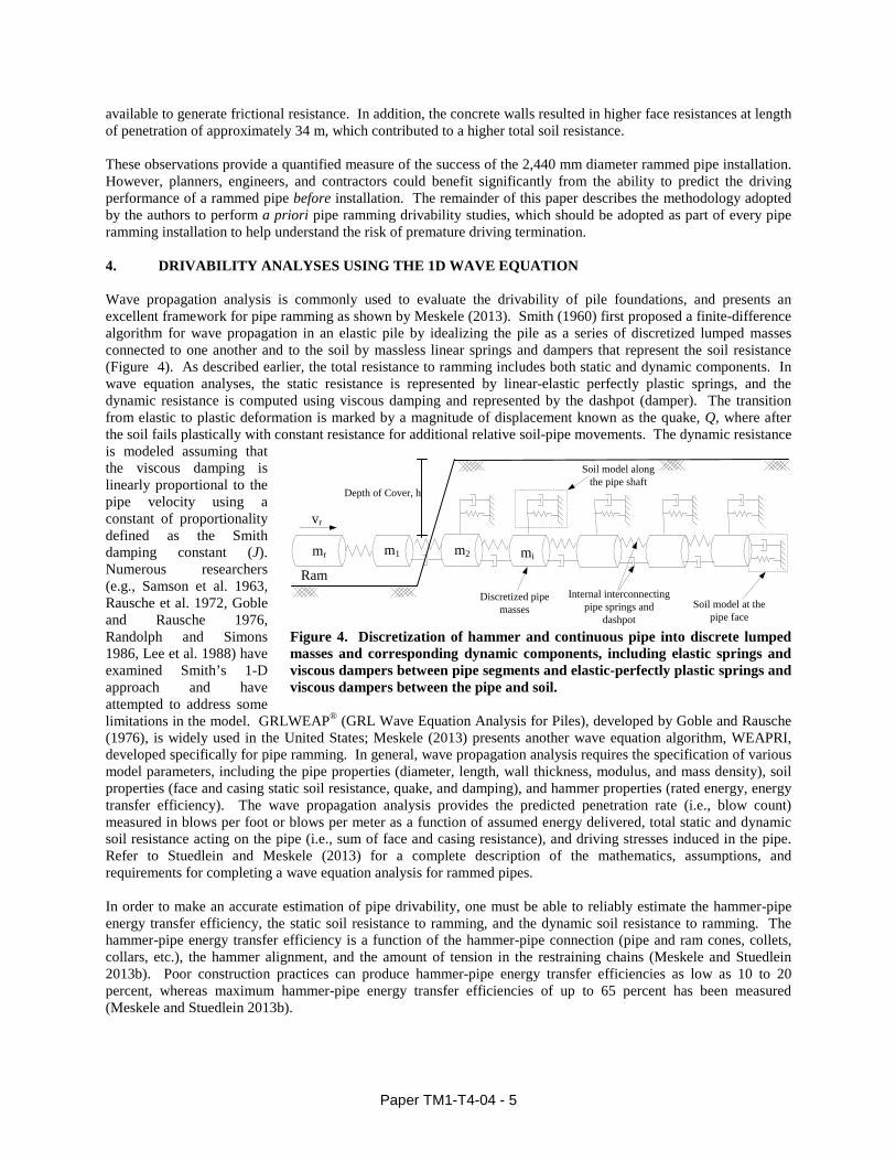
available to generate frictional resistance. In addition, the concrete walls resulted in higher face resistances at length of penetration of approximately 34 m, which contributed to a higher total soil resistance. These observations provide a quantified measure of the success of the 2,440 mm diameter rammed pipe installation. However, planners, engineers, and contractors could benefit significantly from the ability to predict the driving performance of a rammed pipe before installation. The remainder of this paper describes the methodology adopted by the authors to perform a priori pipe ramming drivability studies, which should be adopted as part of every pipe ramming installation to help understand the risk of premature driving termination. 4. DRIVABILITY ANALYSES USING THE 1D WAVE EQUATION Wave propagation analysis is commonly used to evaluate the drivability of pile foundations, and presents an excellent framework for pipe ramming as shown by Meskele (2013). Smith (1960) first proposed a finite-difference algorithm for wave propagation in an elastic pile by idealizing the pile as a series of discretized lumped masses connected to one another and to the soil by massless linear springs and dampers that represent the soil resistance (Figure 4). As described earlier, the total resistance to ramming includes both static and dynamic components. In wave equation analyses, the static resistance is represented by linear-elastic perfectly plastic springs, and the dynamic resistance is computed using viscous damping and represented by the dashpot (damper). The transition from elastic to plastic deformation is marked by a magnitude of displacement known as the quake, Q, where after the soil fails plastically with constant resistance for additional relative soil-pipe movements. The dynamic resistance is modeled assuming that the viscous damping is linearly proportional to the pipe velocity using a constant of proportionality defined as the Smith damping constant (J). Numerous researchers (e.g., Samson et al. 1963, Rausche et al. 1972, Goble and Rausche 1976, Randolph and Simons 1986, Lee et al. 1988) have examined Smith’s 1-D approach and have attempted to address some limitations in the model. GRLWEAP® (GRL Wave Equation Analysis for Piles), developed by Goble and Rausche (1976), is widely used in the United States; Meskele (2013) presents another wave equation algorithm, WEAPRI, developed specifically for pipe ramming. In general, wave propagation analysis requires the specification of various model parameters, including the pipe properties (diameter, length, wall thickness, modulus, and mass density), soil properties (face and casing static soil resistance, quake, and damping), and hammer properties (rated energy, energy transfer efficiency). The wave propagation analysis provides the predicted penetration rate (i.e., blow count) measured in blows per foot or blows per meter as a function of assumed energy delivered, total static and dynamic soil resistance acting on the pipe (i.e., sum of face and casing resistance), and driving stresses induced in the pipe. Refer to Stuedlein and Meskele (2013) for a complete description of the mathematics, assumptions, and requirements for completing a wave equation analysis for rammed pipes. In order to make an accurate estimation of pipe drivability, one must be able to reliably estimate the hammer-pipe energy transfer efficiency, the static soil resistance to ramming, and the dynamic soil resistance to ramming. The hammer-pipe energy transfer efficiency is a function of the hammer-pipe connection (pipe and ram cones, collets, collars, etc.), the hammer alignment, and the amount of tension in the restraining chains (Meskele and Stuedlein 2013b). Poor construction practices can produce hammer-pipe energy transfer efficiencies as low as 10 to 20 percent, whereas maximum hammer-pipe energy transfer efficiencies of up to 65 percent has been measured (Meskele and Stuedlein 2013b).
Rammi
Soil model along the pipe shaft
Soil model at the pipe face
Discretized pipe masses
Internal interconnecting pipe springs and
dashpot
vr
m1 m2mr
Depth of Cover, h
Figure 4. Discretization of hammer and continuous pipe into discrete lumped masses and corresponding dynamic components, including elastic springs and viscous dampers between pipe segments and elastic-perfectly plastic springs and viscous dampers between the pipe and soil.
Paper TM1-T4-04 - 5

vfr σλ ′⋅=
( )φλ ′⋅⋅= tanexp ba
rn φµ ′⋅= tan
iniicr ,, σµ ′⋅=
Meskele (2013) and Stuedlein and Meskele (2013) outline new pipe ramming-specific face and casing static soil resistance models based on full-scale field observations. The unit face resistance, rf, can be estimated using:
[3] where λ is the coefficient of unit face resistance and σ'v is effective overburden stress considering the depth of cover above the center of the pipe (i.e., the springline). The coefficient of unit face resistance is assumed to vary exponentially with the tangent of the internal angle of friction due to the similarity between face resistance of driven pipes and toe resistance of driven pile foundations, and given by:
[4]
where a and b equal 0.011 and 7.22, respectively, for the observed pipe ramming installations in medium dense to dense granular soils, and φ’ equals the peak friction angle. The total static face resistance may then be calculated as the product of projected cross-sectional area of the leading edge of the pipe (typically the cutting shoe and the unit face resistance. When ramming through a uniform granular embankment, the toe resistance will only change as a function of the effective overburden stress. The unit casing resistance, rc, is a function of the normal effective stress acting on the circumference of the pipe, σ’n, and the residual friction angle, φ’r of the soil. The normal stress may be estimated using Terzaghi (1943) trapdoor theory and described by Stuedlein and Meskele (2013). The pipe ramming-specific pipe-soil interface friction coefficient, µ, is given by
[5] where n represents an interface friction reduction constant and was back-calculated from the instrumented pipes observed by Stuedlein and Meskele (2013), and equals 0.15 and 0.22 for lubricated and non-lubricated rammed casings, respectively. Once the average normal effective stress, residual friction angle, and coefficient of friction is estimated for each unit, i, of soil penetrated by the pipe, the unit casing resistance may be estimated using:
[6] and the total casing resistance estimated as the sum of the product of the unit casing resistance and the circumferential area of the pipe. The last components required to estimate pipe drivability are the dynamic soil model parameters for the face and casing, including the quake, Qf and Qc, and the Smith damping coefficients, Jf and Jc, for the face and casing, respectively. Meskele (2013) and Stuedlein and Meskele (2013) describe the methodology used to determine the quake and damping coefficients from the field observations, and determined that satisfactory estimates of pipe drivability may be generated using the average of the observed values, equal to 2.4 mm for both the face and casing quake (i.e., Qf and Qc), and 2.0 and 1.6 sec/m for the face and casing damping (i.e. Jf and Jc), respectively. 5. DRIVABILITY ANALYSIS OF THE 2,440 mm DIAMETER PIPE Drivability analyses were carried out for the 2,440 mm diameter pipe for two of four specific hammer strikes identified for signal matching analyses, which allows accurate determination of dynamic soil model parameters based on stress wave measurements (see Meskele 2013 for details). The two selected hammer strikes correspond to an initial blow (Blow 14) at a penetration of 8.2 m, and Blow 1885 at a penetration of 20.1 m. The hammer-pipe energy efficiency was relatively low, at 17.7 percent, for Blow 14 due to relatively loose chain tension; the efficiency subsequently increased and was maintained throughout the drive (Figure 3a). For example, the hammer-pipe energy efficiency for Blow 1885 was 42.2 percent. Blow 7673 and 9324 at penetration lengths of 34.4 m and 36.6 m, respectively, were also analyzed using signal matching but were not analyzed for drivability herein as these blows correspond to the penetration of the pipe through the concrete wing walls. The software package GRLWEAP was used to simulate the pipe drivability using the properties and geometry of the 2,440 mm diameter pipe and the average observed dynamic soil model parameters, as described above, for a range in static soil resistances.
Paper TM1-T4-04 - 6

Figure 5 presents the comparison of observed and computed penetration resistance for Blows 14 and 1885. The curves indicate how the penetration resistance (in blows per meter, b/m) vary with the estimated magnitude of static soil resistance at a given penetration length and with the amount of hammer-pipe energy transfer efficiency. Two drivability curves are shown in Figure 5a, corresponding to the instantaneous observed hammer-pipe energy transfer efficiency for that blow (i.e., 17.7 percent) and the average efficiency observed over the duration of ramming (42 percent). Clearly, the hammer-pipe energy transfer plays a significant role in drivability (Meskele and Stuedlein 2013); therefore, the ability to predict drivability hinges on the ability to estimate the efficiency of a given hammer-pipe connection. Figure 5a compares the observed penetration resistance, equal to 550 b/m and 400 kN, to that computed at the measured efficiency, 315 b/m and 377 kN. In this case, the static soil resistance computed using Eqs. [3] through [6] was within 6 percent of that measured. The penetration resistance, however, was about 40 percent of that observed, which means that the rate of penetration calculated (i.e., 1.75 minutes per meter of pipe) was about 1.75 times that observed (i.e., approximately 3 minutes per meter of pipe). However, the difference between the observed and calculated duration to ram a segment of pipe is not significant compared to the duration required to provide a full penetration weld of adjoining pipe segments. Owing to the similarity between the observed and average hammer-pipe energy transfer efficiency, only one drivability curve was simulated for Blow 1885. In this case, the static soil resistance was overestimated by approximately 100 percent, but the calculated penetration resistance, at 810 b/m, was within 25 percent of that observed (approximately 600 b/m).
0 1000 2000 3000 4000 5000Penetration Resistance (blows per meter)
Calculated Assuming 42% Efficiency
Observed Penetration Resistance
Calculated Penetration Resistance
0
400
800
1200
1600
2000
0 1000 2000 3000 4000 5000
Stat
ic S
oil R
esis
tanc
e (k
N)
Penetration Resistance (blows per meter)
Calculated Using Measured EfficiencyCalculated Assuming 42% EfficiencyObserved Penetration ResistanceCalculated Penetration Resistance
Figure 5. Comparison of observed and computed pipe drivability for (a) Blow 14 at an embedment of 8.2 m and with a measured hammer-pipe energy transfer efficiency of 17.7 percent, and (b) Blow 1885 at an embedment of 20.2 m length with measured hammer-pipe energy transfer efficiency of 42.2 percent. Solid markers indicate estimated static soil resistance and corresponding penetration resistance. Drivability analyses also provide the maximum driving stresses anticipated during a pipe ramming installation. Table 1 compares the maximum compressive and tensile stresses observed for Blows 14 and 1885 to the stresses computed using the 1D wave equation analyses. When the actual hammer-pipe energy transfer efficiency is used in the drivability analyses, the computed stresses are similar, though higher (i.e., conservative) than those observed. However, if the hammer-pipe energy transfer efficiency is overestimated, the stresses will likewise be overestimated as the force applied to the pipe by the hammer will be larger than that experienced in the field. Note that for the hammer and observed hammer-pipe energy transfer efficiencies, all of the computed stresses were well below the allowable driving stress (equal to 217 MPa) for this pipe. Although compressive stresses are usually greater than tensile stresses due to the nature of the hammer blow and interaction with the surrounding soil, the magnitudes of the tensile stress could be critical for pipes with poor quality connections. For example, a rammed pipe could separate at the welds if inferior or non-fully penetrating welds are accepted and placed into service due to the locally increased tensile stresses associated with a reduced weld seam area. The estimated tensile driving stresses should be compared to the tensile capacity of alternative pipe joining systems if welding is not selected for joining rammed pipes.
Paper TM1-T4-04 - 7

In general, the goal of the drivability analysis is to optimize the hammer energy applied to the pipe, whereby the optimal hammer provides the smallest energy needed to advance the pipe at the desired penetration resistance for the last meter of penetration in the drive. Additionally, the driving stresses should be kept below the allowable driving stress, given by nine-tenths of the yield stress of the pipe. For the case considered in this paper, it was shown that the hammer selected was able to install the 2,440 mm diameter pipe will little difficulty and with no danger of over-stressing the pipe. It is also noted that drivability curves will typically reach an asymptote of static soil resistance with increased penetration resistance, representing the case for which a given hammer will not be able to penetrate a given soil unit. This case is termed “effective refusal”, and planners should avoid this condition when sizing hammers for use in pipe ramming installations. In the case where effective refusal is a possibility, a hammer with greater energy should be selected for drivability evaluation.
Table 1. Comparison of observed and computed driving stresses for the instrumented 2,400 mm diameter pipe. Note, the allowable stress was equal to 217 MPa; E = hammer-pipe energy transfer efficiency.
Case
Maximum Compressive
Stress Observed
(MPa)
Maximum Calculated Compressive Stress (MPa)
Maximum Tensile Stress
Observed (MPa)
Maximum Calculated Tensile Stress (MPa)
E = 17.7 % E = 42% E = 17.7 % E = 42%
Blow 14 30.3 31.8 55.6 25.0 30.0 51.3
Blow 1885 49.0 - 55.6 41.7 - 49.2
6. CONCLUSIONS This paper presented the case history of a large diameter instrumented pipe installed using pipe ramming under a highway embankment, adding to the small number of data-rich case histories available for reference by users of trenchless technology. The driving performance of the pipe was described in terms of maximum energy transferred to the pipe, compressive driving stresses, and total static and dynamic soil resistance for penetrations ranging from 8.2 to 36.5 m of length. The driving performance indicated that energy transfer was fairly low at the start of the second segment of driving, but that continuous monitoring and maintaining of chain tension allowed a relatively good average hammer-pipe energy transfer efficiency of about 42 percent to be achieved. A methodology for performing drivability of rammed pipes was described, and used to compute the penetration resistance and driving stresses in the instrumented pipe. In general, the wave equation analyses satisfactorily predicted the driving performance of the pipe provide the hammer-pipe energy transfer efficiency could be accurately estimated. The findings in this paper highlight the importance and advantages of performing pipe drivability analyses before construction to ensure that the hammer selected can achieve the required penetration length without over-stressing the pipe. Owners, consultants, and contractors are encouraged to add drivability analyses of rammed pipes to their toolbox when planning pipe ramming projects to help mitigate the potential risk for effective pipe refusal and damage. 7. ACKNOWLEDGEMENTS The authors gratefully acknowledge support from the Oregon Department of Transportation (ODOT) and Federal Highway Administration (FHWA) through Research Contract SPR-710. This case history was carried with the cooperation of Ontario Ministry of Transportation (MTO), Golder Associates, and Jim Robinson Contracting. This study was carried out with significant support of the Oregon and Southwest Washington Chapter of the National Utility Contractors Association (NUCA). The second author was partially supported by a scholarship from the Pacific Northwest Transportation Consortium (PacTrans). The assistance provided to the authors is gratefully acknowledged.
Paper TM1-T4-04 - 8

7. REFERENCES ASTM. (2008). “Standard test method for high-strain dynamic testing of deep foundations,” ASTM D4945,
American Society for Testing and Materials, West Conshohocken, PA.
Holcomb, D. (2012) “Failing 96-inch Diameter CMP Replaced Utilizing Pipe Ramming Technology,” Proceedings of No-Dig 2012, North American Society for Trenchless Technology, Nashville, TN, pp.7.
Goble G.G., Likins G. and Rausche F. (1975) "Bearing capacity of piles from dynamic measurements," Final Report, Department Of Civil Engineering, Case Western Reserve University, Cleveland, Ohio, Pp.77.
Goble, G.G. and Rausche, F. (1976) “Wave Equation Analysis of Pile Driving – WEAP Program,” Implementation Package IP-76-14.1 – IP-76-14.4, U.S. Department of Transportation, FHWA, Washington, D.C.,.
Goble G.G., Rausche F. and Likins G. (1980) "The Analysis of Pile Driving - A State-of-the-Art," Proceedings of International Seminar on the Application of Stress-Wave Theory on Piles, pp.131-161.
Lee, S., Chow, Y., Karunaratne, G., and Wong, K. (1988) “Rational Wave Equation Model for Pile‐Driving Analysis,” J. of Geotechnical Engineering., 114(3), 306–325.
Meskele, T. and Stuedlein, A.W. (2011) “Performance of an Instrumented Pipe Ramming Installation,” Proceedings of No-Dig 2011, North American Society for Trenchless Technology, Washington D.C., 11 pp.
Meskele, T. (2013) “Engineering Design and Analysis of Pipe Ramming Installations,” Ph.D. Thesis, School of Civil and Construction Engineering, Oregon State University.
Meskele, T. and Stuedlein, A.W. (2013a) “Analysis of a 610-mm Diameter Pipe Installed Using Pipe Ramming,” J. of Performance of Constructed Facilities, ASCE, In Press, accessible at: http://ascelibrary.org/doi/abs/10.1061/(ASCE)CF.1943-5509.0000463
Meskele, T. and Stuedlein, A.W. (2013b) “Hammer-Pipe Energy Transfer Efficiency for Pipe Ramming,” Proceedings of No-Dig 2013, North American Society for Trenchless Technology, Sacramento, CA. 10 pp.
Randolph, M. F., and Simons, H. A. (1986) “An improved soil model for one dimensional pile driving analysis,” Proceedings, Third International Conference on Numerical Methods in Offshore Piling, Nantes, France, 3-17.
Rausche, F., Moses, F., and Goble, G., (1972) "Soil resistance predictions from pile dynamics," J. of the Soil Mechanics and Foundation Division, ASCE, pp 917-937.
Rausche, F., Goble, G. and Likins, G. (1985) "Dynamic determination of pile capacity," J. of Geotechnical Engineering, ASCE, 111 (3), pp 367 – 383.
Robinson, J. (2012) Personal Communication.
Samson, C.H., T.L. Hirsch and L.L. Lowery. (1963) “Computer Study of Dynamic Behavior of Piling,” J. of the Structural Division, ASCE, Vol. 89, No.ST4, pp.413-449.
Smith, E.A.L. (1960) “Pile driving analysis by the wave equation,” J. of the Soil Mechanics and Foundation Engineering Division, ASCE, 86(4): 35–61.
Stuedlein, A.W., and Meskele, T. (2012) “Preliminary Design and Engineering of Pipe Ramming Installations,” J. of Pipeline Systems Engineering and Practice, ASCE, 3(4), pp. 125-134.
Stuedlein, A.W., and Meskele, T. (2013) “Analysis and Design of Pipe Ramming Installations,” ODOT Research Report, SPR 710, Oregon Department of Transportation. In Press.
Paper TM1-T4-04 - 9