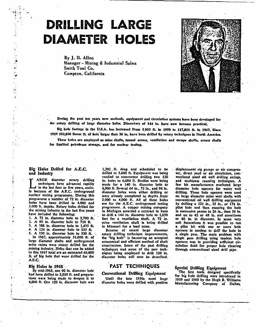
DRILLING LARGE DIAMEER HOLES - nrc.gov · mine ventilation shaft is being drilled in Missouri for a...
20
v I i I i i I I II i I II DRILLING LARGE DIAMEER HOLES By J. H. Allen Manager - Mining & Industrial Sales 'Smith Tool Co. Compton, California Swa1rooL CO. DIVISION OF SMITH INTERNATIONAL. INC. -: 6402010o 44 8 8308 19 -
Transcript of DRILLING LARGE DIAMEER HOLES - nrc.gov · mine ventilation shaft is being drilled in Missouri for a...

v
I
iI
iiI
III
i
I
II
DRILLING LARGEDIAMEER HOLES
By J. H. AllenManager - Mining & Industrial Sales'Smith Tool Co.Compton, California
Swa1rooL CO. DIVISION OF SMITH INTERNATIONAL. INC.
-: 6402010o 44 8 8308 19 -
k I,
DRILLING LARGEDIAMETER HOLES
I By J. H. AllenManager - Mining & Industrial SalesSmith Tool Co.Compton, California
During the past ten years new methods, equipment and circulation systems have been developed forthe rotary drilling of large diameter holes. Diameters of 144 In. have now become practical
Big. hole footage In the US.A. has Increased from S.000 ft. In 1959 to 117,000 ft. In 1967. Since1959 500,000 linear ft. of hole larger than 36 In. have been drilled by rotary techniques In North America.
These holes are employed as mine shafts, tunnel access, ventilation and escape shafts, access shaftsfor riquified petroleum storage, and for nuclear testing.
Big Holes Drilled for A.E.C.and IndustryT ARGE diameter rotary drilling* techniques have advanced rapidly
* -I..in the last four or five years, main-ly because of the A.E.C. undergroundnuclear testing programme. During thisprogramme a number of 72 in. diameterholes have been drilled to 4,000 and
. 5.000 ft. depths. Rotary holes drilled forthe mining industry in the last five yearshave included the following:1. A 72 in. diameter hole to 2,790 ft.2. A 90 in. diameter hole to 710 ft.3. A 108 in. diameter bole to 1,435 ft.4. A 124 in. diameter hole to 935 ft.S. A 130 in. diameter hole to 520 ft..
In 1967, approximately 51.000 ft. oflarge diameter shafts and undergroundmine raises were rotary drilled for theInining industry. Holes that can be added
- 0o this 1967 total are an estimated 66,000ft. of big hole that were drilled for theA.E.C.
Big Holes in 1968By mid-1968, one 90 in. diameter hole
had been drilled to 5,000 ft. and prepara-lions were being made to deepen it to6,000 ft. One 120 in. diameter hole was
1,392 . ft. deep and scheduled to bedrilled to 5,600 ft. Equipment was beingreadied to commence drilling two 120in. holes to 6.000 ft. Studies were beingmade for a 140 in. diameter bole to6,000 ft. Several 64 in., 72 in., and 96 in.diameter holes were either drilling orwere already completed to depths from2,000 to 4,000 ft. All of these holesare for the A.E.C. underground testingprogramme. A copper mining companyin Michigan awarded a contract in Juneto drill a 144 in. diameter hole to 1,650feet for a ventilation shaft. A 72 in.mine ventilation shaft is being drilledin Missouri for a lead mine.
Because of recent large diameterrotary drilling technique improvements,the "big hole" is becoming an acceptedeconomical and efficient method of shaftconstruction. Some of the past drillingtechniques and some of the new tech-niques being employed to drill 120 in.diameter holes will now be described.
PAST TECHNIQUESConventional Drilling Equipment
Until the late 1950s most largediameter holes were drilled with positive
displacement rig pumps or air compres-sor, direct mud or air circulation, con-ventional sized oil well drilling strings,and multipass reaming techniques. Afew bit manufacturers marketed largediameter hole openers for water welldrilling. These hole openers were usedon large diameter mine vent shafts withconventional oil well drilling equipmentby drilling a 12* in., 15 in., or 17* in.pilot hole and then reaming the holein successive passes to 26 in., then 36 in.and on to 42 or 48 in. and sometimesto 60 in. in diameter. In some verysoft formations it was possible to runa pilot bit with one or more holeopeners in tandem to drill the bole ina single pass. The main problem withsingle pass drilling using tandem holeopeners was in providing sufficient cir-culation fluid for proper hole cleaningthrough conventional sized drill pipe.
Special Drilling EquipmentThe first tools designed specifically
for big hole drilling were introduced in1959 and 1960 by the Hugh B. WilliamsManufacturing Company of Dallas,
I

in 24 hours to 200 ft. with a singlepass but without a pilot bole. Afterseveral more single pass holes weredrilled without experiencing deviationor lost circulation problems, several en-gineers and contractors questioned theneed for pilot holes and multipass ream-ing.
it was concluded and later provedthat a large diameter hole drilled with
iic' A'6>\ ZlS .i % { lti t p Af 250 a properly designed (reamer and stabil--m ^ 1 8ton, 12 n. .D. iser equipped) drill collar assembly could
I a r g e diameter be drilled as straight or even straighterrotary d * iini than most small diameter pilot boles.
9,;iswiX~t~vels. Many engineers also concluded that lostcirculation could be either controlled ina big hole, or that circulation techniquescould be altered to prevent lost circu-lation.
Air Foam Circulation TechniquesIn 1962, drilling engineers with Reeco,
the A.E.C. support contractor, perfectedan air-foam circulation method for tan-dem hole opener and other single pass
Texas. These tools consisted of the fol-lowing equipment:
1. A 14 in. x 12 in. centrifugal pump, . +.*
capable -of pumping 7,000 gpm. at110 ft. of discharge head.
2. A 12 in. IbD. xanft. long rubber .. -rotary hose.40 A 250 ton drilling swivel with a12 in. IDl. wash pipe.
4. A 14 in. square x v0ft. long kelly - -. '. .- J)with a 12 in. bore.
S. A string of 131 in. OD, d -55 drillcpipe with splined tool joint con-nections.
6. Foura40oin, 0or . xl tft. 10 in. long ..drill collars weighing 42,000 pounds 5p. .*' l l ,. t .5
each. The drill collars were equipped jwith 40 in. Rlanges on the ends forF.bolting together. The annulus of eachcollar between the 12 in. bore and40 in. shell was filled with lead.
Single Pass Drilling MethodsIn 1960, a uranium mine ventilation
shaft was drilled with the large borespecial tools. A 710 ft. deep, 15 in.pilot hole was reamed to 90 in. indiameter in a single pass. Many engi--neers and contractors believed that apilot hole was still necessary eventhough a big hole could be drilledefficiently in a single pass with the newtools. The pilot bole served as an ex- L 1-
ploration or test hole to check for lost 5~5A-
circulation zones and formation changes ' . fand served as a guide to drill the bigger ~ ~ ~ -- ~f,4hole straight. 1 ___ .,. p •
In 1961, the special equipment was -used to drill a 60 in. diameter hole
- _ __ --. - - -, - - __ ' _-. - . I ... - -

for the fractured formations. The firstreverse air circulation technique, used inthe upper dry sections of the formation,consists of blowing approximately 24,000cubic ft. per minute of air, at approxi-mately 4 to 8 p.sLi. pressure, throughthe rotating head and down the annulus,with the air and cuttings returning tothe surface through the drill pipe. Mineventilation rotary blowers are used tocirculate the air.
The second reverse circulation airtechnique is used below the water tableand employs a dual drilling string.A 7 in. casing string is installed onthe inside and concentric to the 131 in.drill pipe. The 7 in. string is landed"in a casing pack-of bowl in the 72 in.bit. High pressure air is pumped downthe 7 in. x 131 in. annulus and throughgas lift valves in the 7 in. string nearthe bottom hole assembly. This passageof air below the water table creates anair lift effect and returns water, air andcuttings to the surface through the 7 in.inner pipe string.
Other Circulation TechniquesOther circulation techniques that have
been employed with success in othertypes of formations are as follows:1. Reverse circulation of mud with air
lift assist. This technique is beingused in the drilling of 120 in.diameter holes and will be discussedin more detail later.
A 120 In. flat bottom bit used in the drilling of emplacement holes for theAtomic Energy Commission.
drilling methods. This circulation methodproved quite successful for single passdrilling in dry or damp, soft formationswhere air circulation was practical. Inthis air-foam circulation technique amixture of bentonite, detergent andchemicals is injected into a direct cir-culating air stream. This mixture pro-duces a steady return flow of foam whichincreases the cuttings carrying ability ofthe circulation media.
A.E.C. Deep Hole DrillingProgramme
In 1963, the A.E.C. .ommenced adrilling programme for drilling 72 in.diameter boles to 3,000 and 4,000 fLdepths. The programme was premised ondrilling the 72 in. holes with speciallydesigned large diameter tools and singlepass methods in fractured and porousformations that were water bearing be-low 2,000 ft. To insure that the holeswould be drilled straight, new type 60 in.diameter drill collars were designed andbuilt as well as new 72 in. reamer andstabiliser assemblies. Larger load carry-ing capacity swivels and large diameterrotating heads or kelly packoff assem-blies were also built. New 72 in. bitand cutter design concepts were tested.
Most big bole bits used prior to 1963had a stringer for a three-cutter pilotbit in the centre. The new 72 in.diameter bits were equipped with centreand outer cutters that cut the hole in aflat bottom profile. Many of the bit
bodies were equipped with shrouds toeffect a better flow of air across thebottom. Larger cutters mounted in yokesor saddles and equipped with sealedbearings were introduced. Two reverseair circulation techniques were developed
120 In. bit and bottom reamer assembly.
. .
horsepower d.c. motor driving the 14 in.x 12 in. centrifugal pump and another850 brake horsepower d.c. motor on aC-350 mud mixing pump. Other elec-trical power is required for lighting andthe 16 shale shaker screen motors.
Rotating Equipment
1. Rotary TablesThe rotary tables in use for the 120
in. holes are new 371 in. tables drivenby chain drives from the drawworks.These tables are rotated from 2 to10 r.p.m.
2. Swivels and Rotary HosesRotary drilling swivels with 750 ton
load ratings and 12 in. I.D. removablewash pipes are used on the 120 in.holes. The swivels are equipped with aflanged connection on top of the 12 in.goose neck for installation of the 3 in.air tubing string and a 7 in. inner cir-culation string. The rotary hoses in useon the 120 in. holes are 12 in. I.D. andhave an oil resistant liner. Flanges areprovided on the ends for bolting to thestandpipe and swivel. These large rotaryhoses are quite stiff and have a mini-mum bending radius of 6 ft.3. Kellys
The kellys are 14 in. square and 60ft. in length. They are equipped withspecial drive bushings that fit the masterdrive slots of the 37* in. rotary table.
Down-Hole Tools1. Drill Pipe
The new drill pipe currently in use on120 in. holes to be drilled below 5,000ft. depth is fabricated from 131 in. O.D.,54 pound per ft. casing, rolled from aspecial grade of steel, X95S. The drillpipe, with tool joints, weighs 65 poundsper fL and varies in length from 42 toabout 45 ft. The total joints are quad-ruple lead with a "Vee" thread form,called a Reed V4. Hughes Tool Co.manufactures a similar tool joint, theH.490, and Drilco manufactures a DI-22tool joint The V4 tool joints are "madeup" to 110,000 ft.-pounds and break out
* at approximately 85,000 ft-pounds oftorque. The tool joints make up with1* turns. The torsional yield strengthof the 131 in. pipe averages from 650,000to 720,000 ft-pounds. The tensile yieldstrength averages from 1,600,000 poundsto 1,800,000 pounds. The pressure lossthrough the drill pipe, when circulating3,400 g.pm, averages about 1.0 p s.i.per 100 ft. or about 60 p.si. for a 6,000ft. string.2. Drill Collar and Reamer-Stabiliser
AssemblyThe 60 in. diameter drill collar assem-
blies in use on the 120 in. holes con-
sist of a series of doughnut shaped castiron weights that fit around a 60 ft.long, 16 in. O.D. centre drill collarmandrel or stem. The drill collar stem,with a tool joint on top, has a Ranged-end, weight support stool at the lowerend. on which the drill collar weightsrest. With all of the weights (sometimesup to 30, weighing a total of 390.000pounds) supported on the weight stool,the drill collar stem is subjected to ten-sile loading only, in nearly all drillingweight conditions.
The cast iron weights are 60 in. indiameter, 161 in. ID., 18 in. thick andweigh 13,000 pounds each. They are ofsplit, interlocking construction, so theydo not have to be installed by insertingover the top of the stem. A bit reamer-stabiliser assembly is fabricated on andis an integral portion of the drill collarweight stool. A similarly designedstabiliser assembly is used on the stemjust below the uppermost weight. Ahold-down clamp keeps the weights andupper stabiliser in place. Each weightnests in the next weight by intermeshinggrooves cast in the top and bottom.
The reamer-stabiliser demountablerollers are 12 in. O.D. and 24 in. inlength and are equipped with greaselubricated anti-friction roller bearings.The bearing elements are protected fromcontamination by pressure compensatedseals. These seals provide bearing pro-tection for either air or mud circulation:Reamer-stabiliser assemblies used on a140 in. hole can be modified for use ina 120 in. hole simply by changingbrackets.
The drill collar, reamer and stabiliserassembly for a 120 in. diameter holeweighs approximately 480,000 pounds.This great weight provides a very good.plumb-bob" effect, or vertical forcecomponent, to keep the bit drilling ver-tical. This effect, coupled with the stiffbottom hole assembly (designed withproper reamers and stabilisers) has vir-tually eliminated deviation in largediameter holes. Holes having no morethan 1 ft. of horizontal displacementat 4,000 ft. of depth have been drilled.
3. Bits and CuttersThe bits used on the first 140 in. sur-
face hole were a Smith Tool Company140 in. flat bottom surface bit equippedwith 26 sealed bearing cutters, and aSmith Tool Company 120 in. flat bottombit (for the hole below the surfacecasing) equipped with 20 sealed bearingcutters. Both bits have 60 in. diametertop flanges for bolting to the 60 in.drill collar assembly. The bits have apickup chamber that is approximately4 in. wide and 24 in. in length.
With reverse circulation, the pickupchamber sweeps the bottom of the holeand transports cuttings and mud to the12 in. centre bore in the bit. There arethree different sizes and types of cutterson the 140 in. and 120 in. bits. Ongauge are six ST type cutters that are15 in. in diameter and 12 in. in length.The inner cutters are type MT and are121 in. in diameter. Two companion MTcutters in the same row cut a 9 in. widepath. The centre cutters are type CTand cut a 24 in. diameter path in thecentre of the hole.
All of the cutters are demountable andare supported by heat treated yokes thatare welded to the bit body base plate.A dull bit can be removed from thedrill collar assembly and be replacedby a bit with sharp cutters in approxi-mately two hours. The dull cutters canbe removed and replaced with newcutters in six hours. Much design anddevelopment work has been done oncutter spacing and cutter quantities inthe various rows. Cutter spacing is pur-posely unbalanced to eliminate harmonicvibrations resulting from rotation. Thenumber of cutters installed in any onerow is carefully considered, so that eachrow will drill the* required area inapproximately, the same time as a cor-responding row, and so that tooth wear*patterns in each row will be similar.
Cutters are designed to provide opti-mum service at a loading of approxi-mately 20,000 pounds each. On a 120 in.bit, this loading would amount to adrilling weight in excess of 400,000pounds. While this much weight can beprovided from the drill collar assembly,it cannot be effectively applied to thecutters because of inadequacies in thehole cleaning and rotary table torquecapacities.
Rapid advancements have been madein the design and manufacture of largediameter cutters in the last five years.Many drilling contractors and engineersbelieve that more cutter improvementsare needed. However, these improve-ments would necessarily still have to beaccompanied by rotary table torque im-provements and better hole cleaningtechniques before any economic benefitwould be derived. In the last five years,on-bottom rotating time has increasedfrom an average of about 30 hours toabout 200 hours. A few contractors haveexperienced 300 hour runs when drilling72 in. holes with air.
Big hole cutters are available fromstocks in several different milled toothtypes and tungsten carbide insert types.In many medium hard to hard forma-
I
1
i
_

"Doughnuts" or drill collar weights that are 60 in. O.D. by 16* in. L.D. by 1 In.high. The weights fit around the 16 in. O.D. stem of the drill collar.
2. Reverse circulation of mud or waterwith a jet eductor. This technique isprimarily used on shallow, largediameter water wells.
3. Reverse circulation of air employinga "vacuum" created with rotaryblowers connected to the drill stringat the surface. Air at atmosphericpressure flows down the annulus ofthe hole, sweeps the bottom of thebole under the bit and returns to thesurface with cuttings through the13f in. drill pipe. It is necessary tohave a cuttings removal separatorupstream of the rotary blowers toprevent cuttings from passing throughthe blowers.
4. Reverse circulation of air by pump-ing high pressure air down a dualdrilling string annulus. The highpressure air is jetted on the bottomof the hole and cuttings and air arereturned to the surface through theinner string of the dual drill string.A jet eductor, activated by other highpressure compressors'at the surface,is tied to the inner string to createa vacuum to further the aid of thereturn flow of air and cuttings.
The techniques of equipment employ-mcnt, casing, cementing and fishingused for the 72 in. holes are similar tothose currently being employed onIF20 in. diameter holes and are dealtwith later.
TECHNIQUES FORDRILLING 120 INCH
HOLESDrilling and Casing Programme1. 140 In. Surface Hole
If the drilling of a deep 120 in.diameter hole' requires a surface hole tocase off water bearing surface forma-tions, the proper hole size will rangefrom 136 in. to 140 in. depending upondepth. On the first 120 in. hole drilledfor the A.E.C, a 140 in. hole was drilledwith a flat bottom bit in a single passto 411 ft. This hole was drilled to 221ft. by direct circulation using a 14 in. x12 in. centrifugal pump. From 221- ft.to 411 ft, the hole was drilled -byreverse circulation air assist using 9.0pound per gallon mud. The 140 in. holewas cased with 122 in. ID. casing withI inch wall thickness. Tbis string weighedapproximately 500,000 pounds (in mud)and was run with the rig hoisting equip-ment. The 122 in. casing was cementedto the surface in three stages by cement-ing in the annulus through 2i in. groutpipes.2. 120 In. Emplacement Holes
The first 120 in. hole is being drilledwith a flat bottom bit in a single passfrom the surface casing at 411 ft. to theprojected depth of 5,600 ft. The drillingtools will weigh approximately 800,000pounds at this depth. Circulation for the
120 in. bole is reverse mud with airassist. A 3 in. air injection. tubingstring was lowered to 360 ft. inside the13 in. drill pipe. By injecting 1,800c.f.m. of air at this depth, the reverseflow rate of mud and cuttings was 3,400g.pim. At this circulation rate, some ofthe penetration rates averaged 2.5 to3.0 ft. per hour. The 120 in. hole willbe cased with 54 in. lD. casing havinga wall thickness-varying from I in. atthe bottom to.# in. thickness at the top.There will be an enlarged casing sectionon the bottom of the 54 in. casing. Thecasing will be cemented to the surfacein several stages through 2* in. groutpipes run in the annulus.
Surface Equipment
1. DmwworksThe drawworks for the 120 in. holes
require the capacity to hoist the 800,000pound drilling tools at a hoisting rateprobably no greater than about 30 ft.per minute. Hoisting tools this heavy atgreater speeds can cause severe shockloading on the derrick, block and tacklesystem, and other components of thehoisting system, if the tools momentarilyhang up in the' hole. Also, it has beenfound that the large diameter bits anddrill collars tend to have a swabbingaction on the hole if they are hoistedtoo rapidly in mud. Drawworks that arebeing used on 120 in. diameter holesinclude National 160 Es and Emsco3000s.2. Derricks
The derricks used on 120 in. holes arerated from 1,400,000 pounds to 2,000,000gross nominal capacity. All are capableof racking in excess of 6,000 ft. of131 in. drill pipe and are designed -forwind loads of 150 miles per hour. Amplefloor space is necessary for setting backdrill collar assemblies and/or handlingthe large diameter casings. One rig hasa special drum, 60 in. crown blocksheave and 54 in. travelling block sheavegrooving to accept a 12 line system ofIf in. drilling line.3. Prime Movers
The ideal power for hoisting heavydrill strings at very low initial hoistingspeed is electrical power from directcurrent motors. All of the rigs currentlydrilling 120 in. holes are diesel electricrigs. Most have at least 3,000 brakehorse power diesel engine capacity. Thediesel engines drive d.c. and ac. gen-erators to supply electrical power. Onerig has five 300 h.p. dc. generatorsand two 350 kVA. am. generators sup-plying power for two 850 brake horsepower d.c. motors connected to the draw-works and rotary table, one 850 brake
=

tions the cutters equipped with tungstencarbide inserts (teeth) experience bear-ing and seal wear before appreciableinsert wear occurs. Some of these tung-sten carbide insert cutters can be rebuiltand re-used by installing new bearingand seal assemblies.
Shown in the appendix is a 140 in.bit run record for the surface bole onthe first 120 in. hole drilled for theA.E.C. This bit was rotated between 4and 6 r.p.m. with 35,000 to 70,000pounds of weight. Circulation was directfrom a centrifugal pump providing only5,000 g.p.m. of mud. All of the cuttershave been graded and listed on therecord as to tooth and bearing wear. TheAAODC eight-point system for grad-ing dull bits was used by a field engineerfor grading these cutters.
The 120 in. bits weigh approximately27,000 pounds while the 140 in. bitsweigh 31,000 pounds.
Casing and. Cementing ProceduresThe 122 in. I.D. x I in. wall casing.
run in the 140 in. surface hole was fab-ricated from A-441 steel. Bands about8 in. wide by i in. thick are installedat intervals on the outside of the 122 in.casing to serve as both casing stiffenerrings and rings for casing elevatorbearing support. The casing with stiffenerbands weighs approximately 1,200 poundsper foot. Double elevators on the righoisting equipment were used to runthe casing in the 140 in. hole. Each20 ft. long section of the casing waswelded as it was lowered in the hole.After the casing was landed, a 10 ft.cement plug was laid in the bottom andon the outside of the 122 in. casing. Thestring was cemented to the surface withtwo different stages of cement pumpedthrough 2* in. tubing strings inserted inthe 140 in. hole annulus.
The 120 in. emplacement holes willbe cased with 54 in. I.D. casing. A5,600 ft. string of this casing will weighapproximately 5,000,000 pounds. Thelong string of casing is run with largediameter hydraulic casing jacks. It willbe cemented to the surface in severalstages to prevent collapse. Approximately280,000 sacks of pre-hydrated gel cementhaving a 1.8 yield factor will be pumpeddown 2i in. tubing strings installed inthe annulus.
Auriliary EquipmentAuxiliary equipment that is in use
or will be available for use in thedrilling and completion of 120 in.diameter holes includes the following:
1. Heavy duty air operated winches onthe rig floor.
AIR Ii
-Iu -IQUID IN
-AERATED
LIOA
P reent Submergenge
t~~~~t^ ~~~~1i2
5. Six pen drilling recorders that recordweight, penetration rate, r.p.m,.torque, air or mud volume, and com-pressor or pump pressure.
6. Deviation instruments with 0 to 11degree chart records.
7. Drilling bridge plugs for 54 in.casing.
8. Retrievable packers for pressure test-ing 54 in. casing. A newly designed54 in. packer can be used in the54 in. casing above the floor to aligntwo joints of casing for welding aswell as for a 3,000 ps.i. burstingpressure test.
Fishing ToolsBig hole drilling has had a number
of very unusual fishing jobs and casingcollapses. The author has been involvedin a number of jobs where bits and com-plete drill collar assemblies were lost inthe hole. In every case, the tools havebeen recovered and the hole cleared,in no longer than two weeks. A varietyof unusual fishing tools have been usedfor big holes. The more common fishingtools are as follows:
1. 13i in. casing spears.2. Dumble or alligator grabs.3. Drilling buckets similar to those em-
ployed in foundation pier hole drill-ing.
4. Large diameter magnets.5. Overshots of 40 and 60 in. diameter.6. Junk catchers 36 in. and larger in
diameter..7. Hydraulically operated grabs.
One of the most difficult fishing jobsever experienced was the recovery ofan AAX casing tong for 131 in. pipelost to a depth of 600 feet in a 44 inhole drilled in granite. This tong wasremoved after about 11 days with aDumble grab.
Big Hole Drilling ContractorsU.S. contractors presently engaged in
drilling large diameter holes and operat-ing equipment capable of drilling 120 in.diameter holes to depths greater than2,000 ft. include the following:
1. Parco Drilling Company, Tulsa,Oklahoma.
2. Shaft Drillers, Inc., Las Vegas,Nevada.
3. Loffland Brothers Company, Tulsa.Oklahoma.
4. Camay Drilling Company, LosAngeles, California.
S. Rowan Drilling Company, Houston.Texas.
Air assisted, reverse liquid circulation.Perhaps the simplest air-assist systemconsists of air injection into the drillpipe liquid column through a smallerconcentric tubing string which is per-forated or open-ended. The aeratedliquid Is then discharged to surface tanks,the air separated and the liquid re-turned to the annulus. The liquid flowsdown to the bit and back up the drill
pipe carrying cuttings with It.
2. A hydraulic line pulling devicehooked to the drill pipe tongs toprovide adequate make up and breakout torque for the tool joints.
3. A hydraulic powered bridge cranemounted in the derrick to assist inracking the 13 in. drill pipe.
4. A heavy duty flat car that runs onrail and straddles the hole is used toconvey dull bits from under the floorand transport sharp bits back to thehole for installation on the collar.
DRILLING LARGE DIAMETER HOLES
PART II
CIRCULATIONTECHNIQUES FOR120 INCH HOLES
- Mud System for 120 inch Holes1. Mud Type and Preparation
In the drilling of the first A.E.C. 120in. diameter holes through water bearing
* formations, it was decided to use a ferro-chrome lignosulphonate light-weight,low-solids mud. The mud was mixed toan initial weight of 8.8 pounds pergallon. Viscosity was controlled at 40 to42 seconds. The mud was mixed in 1,500barrels of steel mixing storage tanks witha G-350 mud pump. It was transferredfrom the mixing tanks to three earthenstorage pits in the mud circulation sys-tem. In drilling the 140 in. hole to 411ft. and then drilling a 120 in. hole to5,600 ft., it will be necessary to mixand/or treat approximately 80,000barrels of mud.
2. Mud StorageThe mud is stored in three earthen pits
of approximately 100,000 total barrelscapacity. The pits were constructed ona favourable terrain so that mud willflow by gravity to the annulus of thedrilled hole. If terrain conditions arenot conducive to gravity flow to thehole annulus, the 14 in. x 12 in. centri-fugal pump, used in drilling the initialportion of the 140 in. surface hole, canbe used to pump mud to the bole.
3. Cuttings RemovalMud, air and cuttings flow from the
drill strings by air lift and through a24 in. flow line to a 66 in. OD. de-aeration standpipe. From the standpipethe mud flows by gravity over 16 shaleshaker screens. From the shale shakersthe mud flows by- gravity back to theearthen storage pits to complete thesystem. If the drilled formations have aswell factor of 50 per cent, as pre-dicted, approximately 33,000 cubic yardsof cuttings will be removed from the
140 in. x 411 ft. deep hole and the120 in. hole to 5,600 ft.
The Air Lift-Reverse MudCirculation Technique1. Background
Air lift pumping is one of the mostsimple methods devised for lifting fluids.Most of the empirical formulae arecopyrighted and were developed byIngersoll Rand from tests on one of theirplant water wells. The system operatesas follows on the 120 in. holes:a. Approximately 1,800 cubic ft. per
minute of air is injected down theinside of the 131 in. drill pipethrough a 3 in. tubing string. Thetubing string is suspended from theswivel goose neck.
b. The 3 in. tubing extends to a depthof approximately 360 ft. below themud level in the hole.
c. The injected air, diffused as finebubbles into the cuttings-ladencolumn of mud in the 131 in. drillpipe, lightens this column.
d. Atmospheric pressure acting on themud column in the annulus of the120 in. hole creates a hydrostaticunbalance and forces the lighter mud,cuttings and air column up the drillpipe at a rate of approximately3,400 gallons per minute.
2. CalculationsShown on figure 17 of the Appendix
is a sketch that depicts and describesair lift pumping terms. The maximum
11
0
aW
0a
A.
15 _ -i -a - I I I oll I
* _ X .ij---ci I 1_11At_I_-
_lt-I - ,_ Ie1-.oa 20 so 40 50 so 70 60 90 K
LIFT, FEET- WATER LEVEL TO DISCHARGE
AIR REOUIRED FOR AIR LIFT PUMPING OF *.o*/GALLON DRILLING MUD
10 110 120
Chart for estimating the air volume required for airlifting 9 Ib./gallon mud.
Lift X Specific Gravity
C log,. (Submergence + 34) X Specific Gravity
34 X Specific Gravity
_ ___. _ ,~~~~~~~~~~~~~~~~
:. . I;
lift for the surface equipment employedon the 120 in. holes is the substructureheight of 24 ft. plus the kelly height of60 ft. (at the uppermost position) plusthe swivel height of 8 ft., or about92 ft. For a lift in this range the Inger-soll Rand data prescribes a submergenceof 70 per cent. The submergence ofthe airline below the mud level at thesurface can be calculate as follows:% submergence =
Length of air lineX 100
Lift plus length of air line
' The formula and chart shown inFigure 18 of the Appendix (not con-tained in this printing) providesinformation on the methods for deter-mining minimum air requirements forlifting 9.0 pounds mud. This chart andthe air line submergence calculationsindicate that only about 1,200 c.f.m.of air and submergence of only 233 ft.would effect a reverse flow of 3,400g.p.m. In actual* practice 1,800 c.f.m.of air injected at 360 produces a 3,400g.p.m. flow. The formula for determiningthe minimum air requirements does notprovide for the weight of the cuttingsthat are in the returning fluid. This dis-crepancy, plus the high friction pressurelosses attributed to a mixture of air,mud and cuttings in the 3 in. x 13* in.annulus, probably accounts for thedivergence between calculated and actualoperating conditions.
On other air lift mud circulationsystems, calculations have never checkedwith actual operating conditions. Thecompilation of accurate air-assist dataon holes drilled with mud would be ofbenefit in improving big-hole circulationtechniques.
3. Triple String-Reverse MudCirculation
A reverse mud circulation-air assisttechnique using a 3 in. air line on theinside of a 7 in. casing string, both insidethe 131 in. drill pipe was tested On a72 in. hole in 1967 and on the 120 in.hole in June, 1968. Approximately 500g.pim. of 900 ps.i. mud were pumpeddown the 131 in. x 7 in. annulus andjetted through the 120 in. bit to the holebottom. The high pressure mud plusapproximately 3,200 g.p.m. of mud fromthe 120 in. hole annulus was returnedto the surface cuttings through the.7 in. inner string. Air injected down the3 in. tubing string effected the reverseflow. The test was short in durationbecause of wash pipe packing leakagein the 12 in. swivel. Instantaneouspenetration rates of up to S ft. per hourin the 120 in. hole were observed withthe high pressure mud jetting on thehole bottom.
New Technique for a 96 inch HoleIn late May of 1968, the senior
drilling engineer of Reeco developed anew reverse circulation .air technique ina 96 in. diameter hole that may offermuch promise for a better circulationmethod for 120 in. holes drilled in dryor slightly wet formations. This circu-lation method is described as follows:1. A 7 in. string of casing is installed
on the inside and concentric to the13i in. drillpipe. The 7 in. stringis landed in a casing pack-off bowlin the bottom of the bit.
2. Approximately 2,500 to 3,000 c.f.m.of air at 110 p.sLi. discharge pres-sure is pumped down the 7 in. by13i in. annulus and through eightI in. nozzles in a 96 in. bit bottom.Injected into this air stream areapproximately 40 barrels of waterper hour.
3. At the surface a large rotary bloweris connected to the 7 in. string, down-stream of a separator that removesthe returning water and cuttings.This low pressure, high volumerotary blower creates 12 in. ofmercury vacuum on the 7 in. stringat -the surface.
4. With this new circulation techniquethe 96 in. hole was drilled from1,875 feet to 1,948 feet in a 12 hourdrilling operation. Some of the 73ft.. of 96 in. hole were drilled atinstantaneous penetration rates of 12ft. per hour. During one 4* hourdrilling period on the 96 in. hole thepenetration rate averaged 8.6 ft. perhour. The formation was describedas a damp, compacted tuff.
CONCLUSIONS
Rapid Growth of LargeDiameter Drilling
The development of large diameterrotary drilling techniques and equipmentin the last nine years has been the mainfactor for the rapid advancements madeby this method of shaft construction. In1959, four holes larger than 36 in. weredrilled in the United States for themining and construction industries. Sixholes greater than 36 in. diameter weredrilled for the Atomic Energy Com-missibn. These ten big holes drilled in1959 would not total more than 5,000ft. Eight years later in 1967, the largediameter hole footage had increased to117,000 ft.
The 'increase in footage of big holesdrilled for the A.E.C. is largely due tothe discontinuance of atmospheric test-ing of nuclear devices. The increase infootage for holes drilled for the miningindustry can be attributed only to the.
V-4 BOX
MANDREL
WEIGHT RETAINER
TOP STABIUZER
WEIGHTS
REAMER STOOLAND BOTTOMSTABILIZER
BIT
IrS 5 la DRAWING 0
Assembly for drilling large diameterholes. Hookload at 4,350 ft. in 120 in.hole will exceed 800,000 lb. despitebuoyancy of the mud column.
economics or cost savings of shaft con-struction by rotary methods as comparedto conventional blasting methods. Facedwith increasing labour costs and theshortage of experienced shaft sinkingman-power, the mining industry will con-sider the rotary drilling method evenmore in the next five years.
Perhaps within the next five years theAtomic Energy Commission's OperationPlowshare will be in full progress. Thisis the A.E.C. programme for peacefulapplications for atomic energy. Studieshave been completed for the constructionof harbours and canals, the extraction ofhydrocarbon from oil shales and tightproducing fomations and the solutionmining of minerals from undergrounddeposits. All of these projects will re-quire large diameter boles.

Comparisons of Large DiameterHoles
Drilling a 72 in. diameter hole atthe rate of 5 ft. per hour, or drillinga 120 in. hole at the rate of 2 ft. perhour does not appear to be an impressivepenetration rate to the oil well drillingcontractor. Several 72 in. holes haveadvanced over 100 fL in a day. The 120in. bole advanced 36 ft. in one 18 hourdrilling period. These penetration ratesfor both holes compare to drilling 12in. hole at the rate of 3,600 ft. per day.A 120 in. hole drilled to 6,000 ft. iscomparable in volume to drilling 600,000fL of 12 in. hole. The drilling of600,000 ft. of 12 in. with one rig overan 18-months period at a penetration rate(during drilling days) of 3,600 ft. perday would be a pleasant accomplishmentfor many drilling contractors. Whilelarge diameter drilling comparisons withoil well drilling are not realistic, thesecomparisons of excavation do indicatethat the big hole techniques and equip-ment employment are efficienL
Needed Improvements inTechniques and Equipment1. Rotating Equipment
Large diameter kellys have beenlengthened to 60 ft. for use with thelonger joints of 131 in. drill pipe.Substructure heights have been increas-ed to provide more room under the rigfloor. These increases in lengths andheights have increased the amount oflift required for the reverse circulation- air lift circulation methods beingused on the 120 in. holes. The de-velopment of a down-the-hole swivelthat would fit in the string just below thekelly would decrease the lift and makethe circulation system much more effici-ent. Down-the-hole swivels have beenused on big holes in Germany andHolland.
If the 120 in. hole cleaning couldbe improved, weights up to 400,000 and500,000 pounds could be run on thebits. Drilling weights of this magnitudewould require rotary table torques inexcess of 400,000 ft. pounds. Largerrotary tables (or large power swivels, assuggested by one contractor) would berequired for bit rotation with increaseddrilling weights.
2. CirculationThe first 200 It of the 140 in. surface
hole is drilled with the centrifugal pumpat a direct circulation rate of 5,000g.p.m. This volume provides an annular,or rising, velocity of only 6.3 ft. perminute. Better hole cleaning and in-creased penetration could be gained by
employing two 14 in. x 12 in. centri-fugal pumps piped in parallel.
Data needs to be compiled on reversecirculation-air lift mud systems in orderthat more accurate calculations can bemade.
A reverse-air circulation system com-parable to the system used by Reecoon the 96 in. should be tested on 120 in.holes.
ACKNOWLEDGEMENTSThanks are expressed to James H.
Allen, the U.S. Atomic Energy Com-mission; Fenix and Scisson Inc.; ShaftDrillers Inc.; Loffland Bros. Co.; CamayDrilling Co.; Parco Drilling Co.; RowanDrilling Co.; Drilco; and Smith ToolCompany for information and photo-graphs.
REFERENCES
1. Allen, James H., 'The SpecialEquipment and Problems Associatedwith Large Diameter Rotary Dril-
ling", ASME Petroleum Mechan-ical Engineering Conference, Kan-sas City, Missouri, September, 1961.
2. Allen, James H., "The Developmentof Large Diameter Rotary DrillingMachines for the Mining and Con-struction Industries". Presented atthe Ninth Annual Drilling Sympo-sium at the Pennsylvania State Uni-versity, University Park, Pennsyl-vania, October 8-10, 1959.
3. Bawcom, J. W., Rotary Drilling ofLarge Diameter Vertical Holes'.Paper presented at the Symposiumon Salt, Cleveland, Ohio, May,1962.
4. Crews, Sim H., "Big Hole DrillingProgress Keyed to Engineering".Published In The Petroleum En-gineer, October, 1964.
5. Dellinger, T. B., "Economic Fac-tors Relative to Drilling Large Dia-meter Holes". Paper presented atthe Second Symposium on Salt,Cleveland, Ohio, May, 1965. TheNorthern Ohio Geological Society,Inc.
6. Holbert, William J., -AdvancementsIn Big Hole Drilling". API PacificCoast Division, Spring Meeting.Bakersfield, California, May. 1968.
7. Kemnitz, George E., "Drilling Pro-Ject Long Shot". Published byDrilling Magazine, July. 1966.
8. Morlan, Erwin A.. "Boring LargeHole Mine Openings", Society ofMining Engineers of AIME. PaperNo. 61, A V27.
9. Presley, Charles K., -Big HoleDrilling Techniques of the AtomicEnergy Commission". API Divisionof Production, Mid-Continent Dis-trict, Spring Meeting, March, 1963,Paper No. 851-37-E.
10. Presley, Charles K., and Glass, Wil-liam A., "Large Diameter ShaftDrilling". SME, Fall Meeting,Rocky Mountains Minerals Con-ference, September, 1967.
11. Wirtz, H. A., "Circulation Systemsfor Large Diameter Holes". Un-published Engineering Report.Hughes Tool Co.
Reprinted by permission of theSOCIETY of MINING ENGINEERS of A.I.M.E., preprint no. 76-AU-67and byWORLD MINING magazine, fromthe January, 1976, issue.
A Review ofReverse Circulation
Air Lift Methods forC Big Hole Drilling
James H. Allen, Director of Technical Services,SMITH TOOL
C - Compliments of 5i SMfWIH TOOLDivision of Smith International, Inc.
P.O. Box C-19511 * Irvine, California 92713' (714)540-7010
ABSTRACT
The air lift method of pumping water is discussed. Areview of several large diameter hole drilling projects thatused reverse circulation air lift techniques is presented.
Proposals are made for reverse circulation flow ratesfor slow rates of bit penetration (5 fph) as well as reversecirculation flow rates for faster rates of bit penetration(10 fph). The Ingersoll-Rand air lift equations are modi-fied for rotary drilling operations.
By establishing minimum reverse circulation flow ratesand utilizing the modified air lift equations, the establish-ment of minimum circulation equipment sizes and a moredefinitive requirement for improved bit body designshould result.
INTRODUCTION
The air lift method of pumping water and other liquidshas been in use for 175 years. It is one of the most simple,yet often misunderstood, pumping methods known.Compressed air is injected through an air line (pipe) anddiffused into a large pipe submerged in a liquid. Bubblesof air rising through the liquid to be lifted, lighten thecolumn and the liquid is elevated by atmospheric pressure.The air can also be injected into the annulus of two con-centric pipes submerged in a liquid and diffused into thecenter pipe for air lifting. See FIGURE 1.
Air lift methods have been used for dredging sand andgravel; agitating viscous liquids; pumping chemicals,brines and corrosive materials and de-watering mines.The principal usage has been connected with water wellswhere the method has been used for well clean-out, waterproduction and well drilling.
Between 1900 and 19601,2 over thirty large diametermine ventilation and access shafts were rotary drilled inGermany and Holland using reverse circulation-air lifttechniques. In the early 1960's3.4 North American DrillingCo. used the method to drill a 130" diameter salt mineshaft in southern Louisiana. During the mid and late1960's6,8,1 air lift drilling methods were used at the AECNevada and Amchitka test sites to drill 72", 90', 96" and -120' holes. Several dual and triple drilling string innova-tions, all using some form of reverse circulation and air,were proposed and tested by the AEC or AEC relatedengineering firms. Outstanding drilling projects that werecompleted during this period included the following:
1. A 90" diameter hole to 6000' depths was drilled byParker Drilling Co. on Amchitka Island in theAleutians.
2. A 120" diameter hole to 5600' depths was drilledby Shaft Drillers in central Nevada.
3. A 120" diameter hole to 4800' was drilled by Loff-land Bros. Drilling Co. in central Nevada.
Most of the AEC holes were drilled with 13W' O.D.drill pipe and circulation system equipment that had a12" to 12%' inside diameter. Reverse circulation-air lift
drilling fluid rates of up to 3400 gpm could be establishedwith equipment of this size. During the period of 1965-1970 reverse circulation technology was advanced by theAEC drilling projects.
REVERSE CIRCULATIONWITH AIR LIFT
I KELLY UkEI II II II g I
PRESSO -- TER
,** ..-I .A I S WIVEL
ISCHARGE HOSE
Figure I
Since 1970 the reverse circulation-air lift techniquehas been used on many construction drilling projectsthroughout the world. Most of the construction drillingprojects have been connected with foundation pile andpier holes. While most of these projects have been verysuccessful, some minor problems and troubles have beenexperienced.
The main problem has been inadequate drilling fluidcirculation rates caused by inadequate equipment size orinsufficient submergence. Inadequate circulation rate,or cross flow under a bit, causes bit flounder and slowpenetration rates.
Before reverse circulation-air lift calculations can bemade, certain criteria must be established such as pro-posed circulation rates, entrance and exit fluid velocitiesand minimum and optimum submergence to lift ratios.
The purpose of the paper is to review the reversecirculation-air lift technique and establish these necessaryparameters for proper rotary drilling calculations.
3

DISCUSSION
Background
The Ingersoll-Rand Company experimented with airlift over a 15 year period in a test water well at one of theirplants. The data compiled and information developed,including empirical formulae, are used universally inair-lift water calculations.
Very little information has been published coveringdata compilations and calculation methods that are neces-sary for rotary drilling systems.
Wirtz" made a study of rotary drilling reverse circu-lation methods for Hughes Tool in 1961, but his work wasnot published. Other studies, mostly unpublished, weremade by various personnel connected with the AEC bighole projects.
Data Requirements and Determinations
There appears to be some lack of understanding bypeople using reverse circulation drilling as to what infor-mation can be calculated and what data is required forthe calculations.
Information or data that is needed for a reverse circu-lation-air lift drilling calculation includes the following:
1. Hole diameter.
2. Hole depth.
3. Hole depth where air lift drilling will commence.
4: Height or distance of lift (distance from fluid levelin hole to top of swivel above Kelly).
5. Size of drill pipe. (Inside and outside diametersfor both single drill string and dual strings.)
6. Size of air line if inside drill string.
7. Type of drilling fluid (including specific gravityor density).
8. Rate of penetration expected or desired.
Calculations that can be made from the above dataare as follows:
1. Submergence of air line (or percent submergence)or amount of hole depth required for minimumsubmergence.
2. Cubic feet of air required per gallon of drilling fluidcirculated. Also total cubic feet of air per minute.
3. Air compression ratio.
4. Discharge velocity of air, drilling fluid and cuttingsat swivel.
5. Entrance velocity of drilling fluid, cuttings and airat point of air injection.
6. Entrance velocity of drilling fluid and cuttings atbit.
7. Required inside diameter of swivel and Kelly ifthese sizes are not predetermined.
8. Required inside diameter of drill string if not pre-determined.
9. Required Kelly length if minimum air line submer-gence requirements cannot be met.
10. Air compressor working pressure.
Circulation Rates
Direct circulation rates or cross flow rates for opti-mum bottom hole cleaning under three cutter bits up to26" diameter have long been established.
In 1961, Morlan9 proposed direct circulation rates forbig holes of Q = 50d.
Where: Q = circulation rate in gpm
d = diameter of hole in inches
This volume recommendation has proved to be satis-factory for drilling holes up to 60" in diameter with water.High volume, low head centrifugal pumps are used withlarge bore circulation equipment. Holes larger than 60'require drilling mud (water plus bentonite for density andviscosity increases) for cuttings removal at rates whereQ = 50d.
Flow rates for reverse circulation with large diameterbits has not been established.
A review of big hole drilling literature revealed thefollowing information pertinent to flow volumes, flowvelocities and bit body fluid pick up methods.
1. The theoretical cross flow or radial flow velocityfor optimum cuttings horizontal transport whenreverse circulating with air is from 4000 to 7500feet per minute.
2. The theoretical radial flow velocity for optimumcuttings horizontal transport 'when reverse circu-lating with water is 600 fpm. Other studies indicatesand and gravel is transported in a stream bed at300 fpm.
3. Vertical transport of cuttings requires an air velocityfrom 3000 to 5000 feet per minute.
4. Vertical transport of cuttings requires a watervelocity from 100 to 120 feet per minute.
5. The reverse circulation rate of 3400 gpm on theAEC 120" diameter holes resulted in a vertical orrising velocity of 535 fpm. The radial flow velocityat the bit periphery was 10 fpm and 535 fpm at thecenter fluid pick up.
6. Reverse circulation bits areiequipped with centerfluid pick up systems for slow drilling in hardformations.
C
0o

7. Reverse circulation bits are equipped with sweepfluid pick up systems for faster drilling in softerformations.
8. To obtain better bottom hole cleaning and higherJ, radial flow velocities, reverse circulation bits have
been equipped with both skirts and shrouds.
The theoretical crossflow of 600 fpm for best horizon-tal transport of cuttings is worthy of consideration butdifficult to achieve with a shrouded, center pick up bit.The radial flow is approximated as follows:
Vr =-
Where: Vr = radial flow velocity in fpm
Q = flow rate in cfm
r = radius from center of bit in ft.
h = distance from hole bottom to shroudon bit bottom in ft.
The reverse circulation rate for a 48" flat bottom bitwith a shroud I h2 from hole bottom and with a 600 fpmradial velocity at a 12' radius is calculated as follows:
(600) (2) (3.14) (12) (1.5)Q =Vr 2 vrh 144 471 cf m
Q = (471) (7.48 gal/ft3 ) - 3523 gpm
C The rate is higher than the direct circulation rate ofQ = 50d or 2400 gpm.
A 1 shroud clearance at a radius of 12' would require2349 gpm for a radial velocity of 600 fpm. A shroud clear-ance of less than I' is probably impractical. To obtain aconstant radial flow velocity of 600 fpm across the bit facewould require an increasing shroud to bottom hole clear-ance toward the bit center.
As discussed later, the radial velocity of 551 fpm ata radius of 4' is in fairly close agreement to the center pickup or bit entrance velocity of 600 fpm that is recommendedfor air lift calculations.
Reverse Circulation Methods
From Gibbs7 the equation for air lifting water is:
Va = LC Log[ + 1
34 J
Where: Va = Volume of air (cfm) pergallon of water
L = Lift in feetS = Submergence of air line in feetC = A constant determined by the over-
all efficiency of the systemand the submergence
For drilling operations, the lift would be from the fluidlevel in the hole to the top of the swivel. For lifts from 20'to 100', which are compatible for most drilling operations,the recommended optimum submergence is 65 to 70%.The minimum rated submergence for this lift range is 50%.
Submergence is the distance the air line is submergedbelow the fluid level in the hole. Percent submergence isthe submergence divided by the submergence plus lifttimes 100.
Submergence x 100% submergence = Submergence + Lift
The constant "C" varies for different percentages ofsubmergence and the values differ depending on whetherthe air is injected through a pipe on the inside of the drillpipe or in a pipe or annular space (dual string) down theoutside of the drill pipe.
Values of "C" are as follows:
The author proposes a minimum reverse circulationrate of Q = IOd for penetration rates to 5 feet per hour.
Where: Q = flow rate in gpmd = hole diameter in inches
An optimum reverse circulation rate of Q = 15d forpenetration rates of 10 feet per hour and greater is alsoproposed. At this rate, the radial flow velocity at mid pointof the gage cutters on a 48" bit with 1 shroud clearancewould be:
PercentSubmergence
30354045505560657075
Inside AirLine140160188214240264288308324338
Outside Air .Line188216248272300316336348356364
Vr = (7.48) (2) (14) (1)= 105 fpm
C At a radius of 4" from center, the radial velocity withI' shroud clearance would be:
Vr = (7 48)((2) (3.14))(4) (1) = 551 fpm
To modify the air lift equation for rotary drilling, itis suggested that the lift and the submergence be correctedfor the specific gravity of the fluid and drilled cuttingsbeing pumped.
a C Log [subergence x S.G. + 34] -
s

When drilling with water at the minimum circulation As-,rates recommended (1Od) and when penetrating at a rateof 5 feet per hour the addition of the drilled cuttings' .weight will increase specific gravity from 1.0 to 1.03 - 1.05on hole sizes from 36 to 72' diameter. If drilling mud isused for hole stability, lost circulation, or prevention offormation fluid encroachment, the specific gravity of thedrilling mud-cuttings mixture should be used to correctlift and submergence.
The most neglected items of the reverse circulationcalculation are the determination of required entrance aarea at the bit and required discharge area at the swivelor rotary hose. When comparing the work done in lifting --
the drilling fluid and cuttings a certain distance to thework done by the air compressor, one would find that theoverall efficiency is probably no greater than 30%. Becauseof this low efficiency, it is essential that the bit entrancearea and the swivel or rotary hose discharge area (and forthat matter the entire rotary drilling string) be of propersize to keep fluid friction losses as low as possible and toget complete expansion of the injected air. These areascan be calculated as follows: Figure 2
72' BIG HOLE BIT - FLAT TYPE
l- A = - (Of + Qa + Qc , FOR REVERSE AIR CIRCULATIONd Vd
to improve bottom hole cleaning. The disadvantages ofWhere: Ad = Area of swivel discharge - in2 bit shrouding are:
Vd = Discharge velocity - fpmQf = Volume of drilling fluid - cfm 1. More design and fabrication time with higher costs.Qa = Volume of free air - cfmQc = Volume of cuttings - cfm 2. The shrouds have to be removed when changing
cutters.Ingersoll-Rand data indicates that the maximum dis-
charge velocity for a lift of 60' is 900 fpm. 3. The shrouds have to be cleaned out occasionallyto prevent cutter locking by cuttings build up.
2. Ae 4 Of + Oa + Qc)Ve
Where: Ae = Area at point of air injection - in2
Ve = Entrance velocity (where idealvelocity would be 600 fpm)
Qf = Volume of drilling fluid - cfmQa = Volume of compressed air at
entrance - cfmQc = Volume of cuttings - cfm
Qa = Volume of compressed air and is determinedas follows:
=Va x gpmCompression Ratio
The Compression Ratio is: O3 5Submergence x S.G. ( 147
Bit Design Considerations _
Design considerations for approaching theoreticalcross flow of 600 fpm on center pick up bits would requirecutter shrouding and flow rates approaching 50d. This Igure3would require very large drill pipe and high air volumes. 72 BIG HOLE BIT - FLAT DESIGN LARGEFIGURES 2 AND 3 illustrate how bits have been shrouded CUTTER TYPE FOR REVERSE CIRCULATION
6
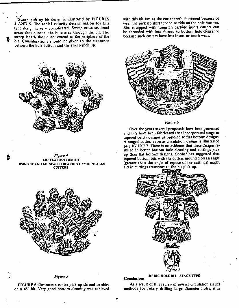
Sweep pick up bit design is illustrated by FIGURES4 AND 5. The radial velocity determination for thistype design is very complicated. Sweep cross sectionalareas should equal the bore area through the bit. Thesweep length should not extend to the periphery of the
'$ bit. Considerations should be given to the clearancebetween the hole bottom and the sweep pick up.
with this bit but as the cutter teeth shortened because ofwear the pick up skirt tended to ride on the hole bottom.Bits equipped with tungsten carbide insert cutters canbe shrouded with less shroud to bottom hole clearancebecause such cutters have less insert or tooth wear.
Figure 6
Over the years several proposals have been presentedand bits have been fabricated that incorporated stage ortapered cutter designs as opposed to flat bottom designs.A staged cutter, reverse circulation design is illustratedby FIGURE 7. There is no evidence that these designs re-sulted in better bottom hole cleaning and cuttings pickup than flat bottom designs. Cobbs5 has suggested thattapered bottom bits with the cutters mounted on an angle(greater than the angle of repose of the cuttings) mightaid in cuttings transport to the bit pick up.
Figure 4136' FLAT BOTTOM BIT
USING ST AND MT SEALED BEARING DEMOUNTABLECUTTERS
Figure 786" BIG HOLE BIT-STAGE TYPEFigure 5
ConclusionsFIGURE 6 illustrates a center pick up shroud or skirt
on a 48" bit. Very good bottom cleaning was achievedAs a result of this review of reverse circulation air lift
methods for rotary drilling large diameter holes, it is
7

believed the following criteria or parameters should beestablished.
1. A minimum reverse circulation flow rate of Q = 10dfor slow drilling rates of 5 fph or less increasing toQ = 15d for faster drilling rates of 10 fph andgreater should be established as a starting pointfor calculations.
2. Rotary hose, swivel and Kellys should be sizedbased on a drilling fluid, cuttings and free air dis-charge velocity of 900 fpm.
3. Drill pipe and bit body pick up tube or sweep sizesshould be based on a drilling fluid, cuttings andcompressed air entrance velocity at 600 fpm.
4. If sufficient starting hole is not available for 50%/submergence to start air lift operations, considera-tion should be given to shorter Kelly and drill stemlengths or other drilling methods to obtain suffi-cient starting hole.
Tables I through IV in the Appendix show the mini-mum fluid discharge and entrance diameters based onthe above criteria and with lifts of 30' and 50' and at sub-mergence percentages of 50% and 70%.
The acceptance of these parameters should result inthe establishment of minimum circulation equipmentsizes for various hole sizes and a more definitive require-ment for improved bit body shroud and fluid pick updesign.
Acknowledgements
The assistance and guidance of Bob Dixon, BobRicks and Jim Boaz of Sii SMITH TOOL in preparingthis paper is appreciated.
References
6. Frederick, R. O.: "The Mighty Bite at UC4",Drilling Magazine, June, 1968.
7. Gibbs, C. W.: Compressed Air and Gas Data,Ingersoll-Rand Company, New York, 1969.
8. Holbert, W. J.: "Advancements in Big Hole Dril-ling", API Div. of Prod., Pacific Coast Divi-sion, Bakersfield, Calif., May, 1968.
9. Morlan, E. A.:"Boring Large Hole Mine Open-ings", 90th AIME Meeting, St. Louis, MO.,March, 1963.
10. Presley, C. K. and Dellinger, T. B.: "Large DiameterShaft Drilling with Reverse Circulation Air,Casing and Cementing for AEC Emplace-ment Holes", API, Div. of Prod., Mid Cont.Dist. Hot Springs, Ark., May, 1964.
11. Wirtz, Howard A.: "Circulation Systems for LargeDiameter Holes", Hughes Tool, 1961;unpublished.
APPENDIX
Sample Calculation
Situation: A contractor has several 48" diameter holesto drill to a depth of 90 feet. The holes can be drilled toa depth of 50 feet with buckets or augers but at this pointhard rock is encountered and a rolling cutter bit and re-verse circulation is required. The distance from theground level to the rig rotary table is 4 feet. The desiredpenetration rate is 10 fph. The rock has an estimated swellfactor of 50% and the density is 160#/ft.3
Determine the following:
1. Circulation rate
2. Percent submergence
1. Allen, James H. - "The Special Equipment andProblems Associated with Large DiameterDrilling," ASME Petrol. - Mech. Engr.Conf. Kansas City Mo., Sept. 1961. PreprintNo. 61-Pet-34, 1961 9 pp
2. Allen, James H.: 'Drilling Large Diameter Holes",Australian Oil and Gas Review, June 1968,10 pp
3. Bawcom, J.W.: "Rotary Drilling of Large DiameterVertical Shafts", North American DrillingCo.; unpublished
4. Bowman, G. A.: "Large Diameter Drilling Meth-ods, Equipment and Problems", DrillingContractor Magazine, Nov. 1964.
5. Cobbs, James H.: "Shaft Drilling State of the Art",Bureau of Mines Contract SO 122047,March, 1973.
3. Volume of air required
4. Specific gravity of drilling fluid cuttings mixture
5. Length of Kelly and bore of Kelly, swivel and hose
6. Lengths and bore of drill pipe
7. Compressor discharge pressure
Solution:
1. Circulation rate = 15d = 15 (48) = 720 gpm, forROP = 10 fph
2. Percent submergence - Starting hole depth = 50'.Assume 2' height for bit = 48' to surface. Holedepth = 90'; 90' - 50' = 40' of hole to drill.Use two 20' lengths of drill pipe to drill from 50'to 90'. With 20' drill stem lengths use a 25' Kelly.Amount of Kelly in hole = hole depth minus bit
a

height minus 40' of drill pipe 50' - 42'= 8'. Assumelift = 25-8 = 17' plus 1' for swivel = 18'
% submergence = Z8 -s-8 x 100 = 73
3. Volume of air required =Lift x S.G.
Va = C Log [submergence x S.G. +
Specific Gravity of Fluid cuttings mixture:
Pounds of water per minute =720 gal/min x 8.33 #/gal = 5997.6
Pounds of rock per minute =.7854 (16) (10) (160 #/ft3) = 335.1
60
Total weight of water and cuttings = 6332.7 #/min.
Cubic feet of water = 720 gal/min = 96.26 ft3/min.7.48 gal/ft 3
Cubic feet of rock = -7854 (16) (10) = 2.09 ft3/min.60
Total volume water and cuttings = 98.35 ft3/min.
6332.7 #1min 6 9 1tDensity of mixture = 98.35 ft3 /min 64.39 #/ft3 /min.
Specific Gravity of mixture = 64.39 #/ft 3 = 1.0362.4 #Ift3 -10
363 18 x 1.03 18.5 .31ft 3 /gala 363 Log r48 x 1.03 + 34 363 Log 2.45
L 34 JVolume of air required = 720 gal/min x .13 ft3/gal
= 94 cfm
4. Specific gravity of drilling fluid-cuttingsmixture = 1.03
5. Length of Kelly = 25'
Bore of Kelly d =
Area = 14 (Qf + Qc + Qa)Vd
Vd = 900 fpm = discharge velocity
Qf = 720 = 96.26 ft3/min7.48 drilling fluid (water)(.7854) (16) 110) 4.19 ft3/mi
(.50) (60) (cuttings)
Qa = 94 ft3 /min free air
Area = 144 = (96.26 + 4.19 + 94) = 31.11 jn2900
d \/ 54-4j =629' (Kelly inside diameter)
Area =14 (Qf + Qc + Qa)Ve
Ve = 600 fpm = entrance velocity
Qf = 96.26 ft/ min (water)
Qc = 4.19 ft3/min (cuttings)
Qa = Volume of compressed air - cfm
CR = Compression ratio =
48 xl1.03 + 1 = 2.46 atstart(2. 31) (1 4.7) of hole
Qa = 94 = 38.2 ft3, min (volume of com-2.46 pressed air)
Area - 1(96.26 + 4.19 +38.2) = 33.28 in2600
d F33. 28 - 6.51" (drill pipe inside.7854 diameter)
CR Compression ratio =
98 x 1.03 + 1 = 3.97 at end(2.31) (14.7) of hole
Qa = 94 = 23.7 ft /min3.97
Area -( 6 96.26 + 4.19 + 23.7) = 29.8 jn2600
d = .785 = 6.19"
N. B. Inside diameter of drill pipe. Kelly swiveland rotary hose should be greater than 6".
7. Compressor discharge pressure
p = Submergence x 1.03 + Air line friction2.31
P =98x 103+ 10% =43.7 +43.7 (.1) =48 psi2.31
6. Length of drill pipe joint = 20'
Bore of drill pipe = d = AreaV7 78-54

TABLE I TABLE III
Rate of Penetration = f [ph, 30' lift, 50% Submergence Rate of Penetration = 5 fph, 50' lift, 50% Submergence
Bit Diam.Inches
364860728496
120
Circ. RateGPM
360480600720840960
1200
Air Vol.CFM
131175219262306349440
Swiv. BoreInches
6.086.977.818.579.2610.0
11.10
Bit BoreInches6.046.907.798.509.189.83
11.0
Bit Diam.Inches
364860728496
120
Circ. RateGPM
360480600720840960
1200
Air Vol.CFM
155207258310362414518
Swiv. BoreInches
6.457.428.409.129.86
10.5011.80
Bit BoreInches .
5.866.707.508.258.929.54
10.70
TABLE 11
Rate of Penetration = 5 fph, 30' lift, 70% Submergence
TABLE IV
Rate of Penetration = 5 fph, 50% lift, 70%0 Submergence
Bit Diam. Circ. Rate Air Vol. Swiv. Bore Bit BoreInches
364860728496
120
GPM360480600720840960
1200
CFM6385
105127148169213
Inches4.865.926.178.307.808.119.10
Inches5.095.406.407.107.508.108.90
Bit Diam. Circ. Rate Air Vol. Swiv. BoreInches GPM CFM Inches
36 360 80 5.2048 480 106 5.8760 600 133 6.6072 720 159 7.2484 840 187 7.8596 960 213 8.40
120 1200 267 9.40
Bit BoreInches4.565.155.806.406.937.418.30
C
TABLE V
Radial flow velocities (Vr) withclearance.
1 shroud to bottom hole
Bit Diam. Circ. RateInches GPM
36 36048 48060 60072 72084 84096 960
120 1200
Vr 6" fromCenter
fpm187249312374437499624
Vr 3" fromPeriphery
fpm75716968676665
C
'A

- i
al .4
PROPOSED REVERSE CIRCULATION RATES0.11%,
PkU%ft.01
wF-*
9
40F-.4
04;DUIx*.04, -, U
wcn9w
wC4
1200
1000
800
600
400
200
030 40 50 60 70 80 90 100 110 120
BIT SIZE (INCHES)Figure 8
I