Drilling Fluid Fundamentals
4
Drilling Fluid Fundamentals
Transcript of Drilling Fluid Fundamentals

8/8/2019 Drilling Fluid Fundamentals
http://slidepdf.com/reader/full/drilling-fluid-fundamentals 1/4
Drilling FluidFundamentals

8/8/2019 Drilling Fluid Fundamentals
http://slidepdf.com/reader/full/drilling-fluid-fundamentals 2/4
W H A T D O E S D R I L L I N G
M U D
D O ?
D R I L L I N G F L U I D P R O P E R T I E S
Removes material (cuttings) from the boreholeThe drilling uid carries the drilled material to the ground surface either by viscosity orvelocity.
Cools and lubricates the bitThe drill bit becomes hot due to friction generated during the drilling process. As the drilling
uid passes through the bit and exits the jets/nozzles, the excess heat is removed and car -ried up the borehole.
Cleans the drill bitWhen the drilling uid exits the bit jets, the uid’s velocity removes material from the bitteeth and the cuttings from the bit formation interface. This prevents the cuttings from beingre-cut or re-ground.
Controls uid lossAs the uid moves from the borehole into the formation, clay particles are deposited onthe borehole wall. The clay particles form a barrier limiting the amount of drilling uid
penetrating the formation. This barrier, called a lter cake, is important for the stability of the borehole. Additionally, well development time is reduced if uid loss to the formationis limited.
Stabilizes the boreholeThe drilling uid’s weight in the borehole must overcome the formation pressure to pre -vent the borehole f rom collapsing. Also, the uid prevents formation swelling by “coating”the formation with an impermeable barrier.
Lubricates the drill pipeThe drilling uid reduces friction between the drill pipe and the rising cuttings, and alsobetween the drill pipe and the formation.
Suspends cuttingsWhen the mud pump stops, the drilling uid velocity stops. The uid must have enoughgel strength to keep the drilled material (cuttings) in suspension until the mud pumpactivates.
Drilling Fluid Properties and Effective Mud Cleaning
Mud rotary drilling is a method of drilling a borehole into the subsurface by rotating a string of drill pipe and bit againstthe formation. By circulating water based drilling uid, the drilled material (cuttings) is carried to the surface. This drillingmethod is used in the environmental or water wells, mining, geotechnical and oil/gas drilling industries.
A complete drilling uid system must be properly designed in order to ef ciently construct a well. The two main parts of the uid system consist of the actual drilling uid, and the solids separation equipment designed to remove the cuttings
from the mud at the surface.
ViscosityResistance to ow. Molasses has a higher viscosity than water. Viscosity is measured by
the use of a Marsh funnel. The device measures the time required for a unit volume of uid (one quart) to drain through the funnel. Fresh water at a temperature of 70° has aow time of 26 seconds through the Marsh funnel.
DensityMass per unit volume. Drilling uid densities are measured in pounds per gallon (ppg).The density of water is approximately 8.3 ppg.
Fluid Loss ControlWater loss and wall building ( lter cake) tests are per formed to API standards by measur -ing the amount of liquid forced from the mud, though a lter paper to a set pressure andtime (normally 100 psi at 30 minutes). The ltrate or water passing through the lter paperand the thickness of the lter cake is measured. Please note that the lter cake does not
structurally prevent the borehole wall from collapsing. The lter cake only minimizes theamount of drilling uid that penetrates into the formation.
Sand ContentSand content is measured as a percent of total uid volume of particles retained on a200-mesh sieve.
Gel StrengthA measure of a uid’s ability to hold particles in suspension. Gel strength is measured on
a concentric cylinder viscometer.Field personnel on a periodic basis, normally measure density, sand content, and uidloss, during drilling operations. The testing equipment is inexpensive and easy to use withminimal training. A typical range of uid properties for drilling in unconsolidated forma -tion are as shown below:
Density Less than 9 poundsPer gallon (ppg)
Filter Cake Approximately 2/32”
sanD Content Less than 1%
VisCosity
32–48 seconds
The above parameters should be modi ed on a site-speci c basis. However, the sandcontent should remain below 1% in order to maintain the proper mud weight and viscos -ity.

8/8/2019 Drilling Fluid Fundamentals
http://slidepdf.com/reader/full/drilling-fluid-fundamentals 3/4
D R I L L I N G
F L U I D
C L E A N I N G E Q U I P M E N T
D R I L L I N G F L U I D C L E A N I N G P R O C E S S
9000 Gallon CapaCity Chemtronportable mud pit
SpeedStar 50K rotary riG and portable mud Cleaner equipped with linearmotion ShaKer tableS
The purpose of a drilling uid cleaning system is to remove the suspending solids (drillcuttings) entrained in the mud. High solids or sand content increases the uid density,
which leads to thefollowing problems:
1 High uid density causes pressure in the formation of the borehole. This pressuredrives the drilling uid through the lter cake into the formation, leads to excessivedrilling uid loss to the formation, and extends well development time required toremove the mud from the formation.
2 As the uid density increases, the pressure required to move the uid up the boreholealso increases, leading to high mud pump pressure requirements.
3 High solids or sand content also leads to signi cant abrasion in the drill tooling as thene particles are recirculating through the mud pump and drill string. Washed out drill
strings and mud pump valves/seats, along with leaking swivel packing, are caused bythe recirculation of sand through the system.
4 If the gravel pack is emplaced in the annulus through drilling uid with a high sandcontent, the nes will be entrained in the gravel pack leading to increased well devel -opment costs and reduced well yields.
Drilling uid in a typical direct mud rotary drilling operation is directed through the fol -lowing path:
1 Clean uid is pumped from the mud pump into a ow line to the drill rig.
2 The drill mud travels down the inside of the drill pipe to the bit.
3 As the uid exits the bit nozzles, heat and drill cuttings caused by friction, are carriedaway from the bit face.
4 The cutting’s laden uid travels up the annulus between the drill pipe and the bore -hole wall.
5 The uid is typically contained at the ground’s surface within an above ground pit atthe drill rig.
6 A transfer pump moves the uid to the cleaning unit.
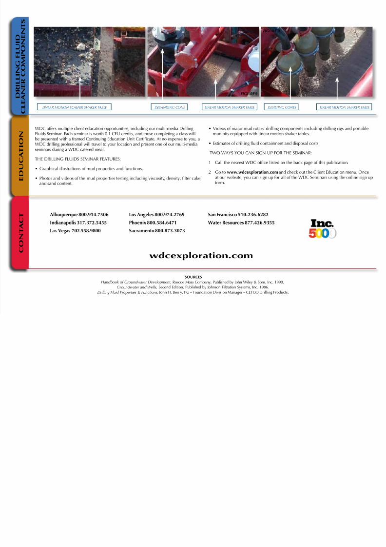
7 The uid enters the uid cleaning system at the “possum belly” and ows across therst linear motion shaker called the scalping shaker. (Figure 1, back page) This “ rst
cut” removes the large cuttings from the mud.
8 The uid falls through the scalping shaker into a pit where some settling occurs.
9 Another pump drives the partially cleaned uid through a set of hydro cyclones, whichremoves sand and silt particles. (Figure 2 & 3, back page)
10 The hydro cyclone discharge is directed onto a second linear motions shaker with smallmesh size screens (140-200), where the sand size particles are removed from the drilling
uid. (Figure 2 & 3, back page)
11 The cleaned mud is then returned to the mud pump and the cycle is repeated.
12 The solids from the linear motion shale shakers are discharged into small transfer hop -pers or roll off containers for disposal. Linear motion shale shakers employ the latest intechnology by allowing a ner screen on the shaker. This results in more solids removedfrom the mud and a drier solids discharge from the unit.
Fluid cleaning systems are portable; they are skid or trailer mounted, and can range intank capacity from less than 500 gallons to over 10,000 gallons. The cleaning rate of theunit should be designed at 150% of the mud pump’s maximum ow rate.
The use of WDC modern linear motion solid separation equipment will increase wellyields, reduce disposal costs, and provide the cleanest possible mud separated from cut -tings from the drilling uid in a virtually dry manner.
8/8/2019 Drilling Fluid Fundamentals
http://slidepdf.com/reader/full/drilling-fluid-fundamentals 4/4
Albuquerque 800.914.7506
Indianapolis 317.372.5455Las Vegas 702.558.9800
Los Angeles 800.974.2769
Phoenix 800.584.6471Sacramento 800.873.3073
San Francisco 510-236-6282
Water Resources 877.426.9355
wdcexploration.com
SOURCESh k f G d v , Roscoe Moss Company, Published by John Wiley & Sons, Inc. 1990.
G w s, Second Edition, Published by Johnson Filtration Systems, Inc. 1986.d g F p s & F c s, John H. Berr y, PG – Foundation Division Manager – CETCO Drilling Products.
WDC offers multiple client education opportunities, including our multi-media Drilling
Fluids Seminar. Each seminar is worth 0.1 CEU credits, and those completing a class willbe presented with a framed Continuing Education Unit Certi cate. At no expense to you, aWDC drilling professional will travel to your location and present one of our multi-mediaseminars during a WDC catered meal.
THE DRILLING FLUIDS SEMINAR FEATURES:
• Graphical illustrations of mud properties and functions.
• Photos and videos of the mud properties testing including viscosity, density, lter cake,and sand content.
• Videos of major mud rotary drilling components including drilling rigs and portable
mud pits equipped with linear motion shaker tables.• Estimates of drilling uid containment and disposal costs.
TWO WAYS YOU CAN SIGN UP FOR THE SEMINAR:
1 Call the nearest WDC of ce listed on the back page of this publication.
2 Go to www.wdcexploration.com and check out the Client Education menu. Onceat our website, you can sign up for all of the WDC Seminars using the online sign upform.
D R I L L I N G F L U I D
C L E A N E R C O M P O N E N T S
E D U C A T I O N
C O N T A C T
figure 1
figure 2
figure 3
linear motion SCalper ShaKer table deSandinG Cone deSiltinG ConeSlinear motion ShaKer table linear motion ShaKer table