Dredging and Reclamation – Ground Improvement · This report provides an overview of potential...
58
Dredging and Reclamation – Ground Improvement Dredging and Reclamation – Ground Improvement Document Ref: AGH-CEPO-EG-REP-0018
Transcript of Dredging and Reclamation – Ground Improvement · This report provides an overview of potential...

Dredging and Reclamation – Ground Improvement
Dredging and Reclamation – Ground Improvement
Document Ref: AGH-CEPO-EG-REP-0018

In May 2016 the Special Minister of State asked Infrastructure Victoria to provide advice on the future capacity of Victoria’s commercial ports. Specifically, the Minister has asked for advice on when the need for a second container port is likely to arise and which variables may alter this timeline. The Minister has also asked for advice on where a second container port would ideally be located and under what conditions, including the suitability of, and barriers to investing in, sites at the Port of Hastings and the Bay West location.
In undertaking this task, Infrastructure Victoria reviewed work that was completed as part of the Port of Hastings development project before it was cancelled in 2014. This document forms part of the initial work undertaken for the proposed port development at Hastings. Infrastructure Victoria considers that much of the previous Hastings work, although preliminary in nature, is relevant and suitable for informing a strategic assessment. Therefore, Infrastructure Victoria has made the reports previously commissioned for the development project part of the evidence base on which Infrastructure Victoria will use in providing the Minister with advice.
The opinions, conclusions and any recommendations in this document are based on conditions encountered and information reviewed at the date of preparation of the document and for the purposes of the Port of Hastings Development Project.
Infrastructure Victoria and its consultants have used the information contained in these reports as an input but have not wholly relied on all the information presented in these reports.

D R A F T
Port of Hastings Development Project – Design and Engineering Dredging and Reclamation – Ground Improvement 27-Feb-15
Port of Hastings Development Project – Design and Engineering
Dredging and Reclamation – Ground Improvement
Client: Port of Hastings Development Authority
ABN: 33 737 350 749
Prepared by the AECOM + GHD Joint Venture
AECOM Australia Pty Ltd Level 9, 8 Exhibition Street, Melbourne VIC 3000, Australia T +61 3 9653 1234 F +61 3 9654 7117 www.aecom.com
+
GHD Pty Ltd Level 8, 180 Lonsdale Street, Melbourne VIC 3000, Australia T +61 3 8687 8000 F +61 3 8687 8111 www.ghd.com
JV ABN: 57 194 323 595
The AECOM + GHD Joint Venture in Australia and New Zealand are certified to the latest version of ISO9001, ISO14001, AS/NZS4801 and OHSAS18001.
© AECOM + GHD Joint Venture. All rights reserved.
This Report has been prepared by the AECOM + GHD Joint Venture for the Port of Hastings Development Authority and may only be used and relied on by the Port of Hastings Development Authority for the purpose agreed between the AECOM + GHD Joint Venture and the Port of Hastings Development Authority as set out in this Report.
The AECOM + GHD Joint Venture otherwise disclaims responsibility to any person other than the Port of Hastings Development Authority arising in connection with this Report. The AECOM + GHD Joint Venture also excludes implied warranties and conditions, to the extent legally permissible.
The services undertaken by the AECOM + GHD Joint Venture in connection with preparing this Report were limited to those specifically detailed in the Report and are subject to the scope limitations set out in the Report.
The opinions, conclusions and any recommendations in this Report are based on conditions encountered and information reviewed at the date of preparation of the Report. The AECOM + GHD Joint Venture has no responsibility or obligation to update this Report to account for events or changes occurring subsequent to the date that the Report was prepared.
The opinions, conclusions and any recommendations in this Report are based on assumptions made by the AECOM + GHD Joint Venture described in this Report. The AECOM + GHD Joint Venture disclaims liability arising from any of the assumptions being incorrect.

D R A F T
Port of Hastings Development Project – Design and Engineering Dredging and Reclamation – Ground Improvement 27-Feb-15
Quality Information
Project Port of Hastings Development Project – Design and Engineering
Document Dredging and Reclamation – Ground Improvement
Ref AGH-CEPO-EG-REP-0018
Date 27-Feb-15
Prepared by Stephen Martin
Reviewed by Ian Cookson
Revision History
Revision Revision Date
Details Authorised
Name/Position Signature
A 21-Jan-15 Draft Peter Fountain Industry Director
B 13-Feb-15 Draft Peter Fountain Industry Director
0 27-Feb-15 Final Working Draft Peter Fountain Industry Director

Port of Hastings Development Project – Design and Engineering Dredging and Reclamation – Ground Improvement 27-Feb-15
Table of Contents
1.0 Introduction 1 1.1 Background 1 1.2 Dredging and Reclamation Work Package 1 1.3 Purpose of this Report 2
2.0 Development Outline 3 3.0 Geotechnical Conditions – Port Area 4
3.1 Regional setting 4 4.0 Dredging and Reclamation 10
4.1 Dredging Methods 10 4.2 Reclamation 11 4.3 Use of clay ball and clay lump fills (Singapore Experience) 12 4.4 Placement Methods and Reclamation Materials 20
5.0 Ground Improvement Requirements 22 6.0 Ground Improvement Techniques 24
6.1 Soil Removal and Replacement 25 6.2 Soil Displacement or Mud-waving 25 6.3 Pre-load Surcharge with or without Vertical Drains 25 6.4 Vacuum Consolidation 27 6.5 Vibroflotation 28 6.6 Dynamic Compaction 29 6.7 Dynamic Replacement 31 6.8 Deep Soil Mixing 31 6.9 Jet Grouting 32 6.10 Semi Rigid Inclusions 33 6.11 Impact Rolling 34 6.12 Deep Foundations or Piling 35
7.0 Ground Improvement Overview 36 7.1 Menard Bachy Budget Estimate 41
8.0 Instrumentation and Monitoring 43 8.1 General 43 8.2 Old Tyabb Reclamation 43
9.0 Example Construction Sequencing 44 10.0 Conclusions 48 References 50
Terminal Footprint Layouts 51 Appendix A
Menard Bachy Budget Estimate 52 Appendix B
Example Construction Sequence 53 Appendix C

D R A F T
Port of Hastings Container Expansion – Design & Engineering Dredging and Reclamation – Ground Improvement 27-Feb-15 1
1.0 Introduction
1.1 Background
The Port of Hastings Development Authority was set up by the Government of Victoria in 2012 to investigate the feasibility of establishing a container terminal at Hastings. This terminal will provide additional capacity to the Port of Melbourne and will also be able to handle larger ships that are unable to access the Port of Melbourne.
1.2 Dredging and Reclamation Work Package
Detailed studies being undertaken as part of other work packages by AECOM/GHD JV and other consultants include:
Geotechnical Interpretation
Channel design for navigation and channel design for construction
Assessment of structure types and terminal layouts
Dredging and reclamation, dredged material management (DMM) and ground improvement of DMM materials placed on land
Environmental assessment
This work package is a sub-component of the dredging and reclamation package of works which is being led by Haskoning Australia. The relationship between this ground improvement work package, the dredging and reclamation work package, and DMM work package is given in Figure 1-1.
Figure 1-1 Total dredged materials management and ground improvement flow diagram (Haskoning, 2015)

D R A F T
Port of Hastings Container Expansion – Design & Engineering Dredging and Reclamation – Ground Improvement 27-Feb-15 2
1.3 Purpose of this Report
This report provides an overview of potential ground improvement options (‘long list’) for dredged materials used for reclamation, considering existing ground conditions, the possible dredging and reclamation work methods, and staging and sequencing considerations. The constraints and opportunities relevant to project specific requirements are also discussed.

D R A F T
Port of Hastings Container Expansion – Design & Engineering Dredging and Reclamation – Ground Improvement 27-Feb-15 3
2.0 Development Outline
Currently the Port of Hastings Development Authority is exploring a range of potential business opportunities and development options. While project definition is currently being resolved, it is anticipated the Port of Hastings expansion and infrastructure development will include the following activities:
Dredging of new or deepened shipping channels, berth pockets, swing basins and anchorages
Beneficial re-use of dredged materials, or disposal to an existing or new dredged material ground inside or outside Western Port
Construction of wharves and shipping berths, including the potential for land reclamation and provision for significant areas of hard stand
New terminal facilities, including container stacking areas and equipment
Port and logistics related developments in the port environs, including road and rail circulation within the port environs
New land use and development associated with the ongoing operation of the port
Upgrade of the arterial road network outside the port environs to increase capacity consistent with the increase in trade
Construction of a new rail line between the port and the existing rail network.
Plans of the Port Area showing the concept options for terminal footprint are provided in Appendix A. Three quay alignments have been considered for the quay structure options assessment as listed below. Further details of the proposed development are provided in the Structural Design Options Assessment Report (AGH-CEP0-EG-REP-0015).
Along the Shore Alignment
Basin Alignment
Straight Alignment
Potential quay structures include open piled quay structures overlying sloping seawalls, bulkhead retaining walls and gravity retaining structures. The terminal area will include quay cranes, ASC modules and associated container stacks, and road and rail infrastructure. The concept terminal drawings are based on the interim terminal static modelling undertaken by Hamburg Port Consultants (HPC) for the Design and Engineering (D&E) workstream.
Existing ground and seabed levels, and associated reclamation depths, vary with the location of the quay line. The range of ground/seabed levels and reclamation depths for each of the three alignments is given in Table 2-1.
Quay Alignment Existing ground/seabed
level
Typical reclamation
depth*
Maximum
reclamation depth*
Along the Shore Alignment +4.0m CD to -10.0mCD 6 m 16 m
Basin Alignment +25.0m CD to -10.0mCD 5 m 16 m
Straight Alignment +2 mCD to -12 mCD 14 m 18m
Table 2-1 Range of reclamation depths
*Based on finished reclamation level of +6.0 mCD

D R A F T
Port of Hastings Container Expansion – Design & Engineering Dredging and Reclamation – Ground Improvement 27-Feb-15 4
3.0 Geotechnical Conditions – Port Area
This section provides a brief summary of the geology of the project area. Details of the geotechnical conditions across the site are provided in the Geotechnical Interpretative Report (AGH-CEP0-EG-REP-0009).
3.1 Regional setting
Near surface materials across Western Port comprise shallow marine deposits underlain by widespread non-marine sands, sandy clays and minor gravels deposited from the Miocene to the early Pleistocene epoch. There are extensive deposits of now stabilized dune sands that were active during Pleistocene glacial times of low sea level. The most recent marine submergence occurred in the last 6,000 years during the Holocene post-glacial rise in sea level. The northern and north eastern margin of the bay was an extensive and low-lying freshwater wetland, now almost completely drained. Extensive stands of mangrove and salt marsh fringe much of the coastline of the bay and the islands. The geology and morphology of Western Port is shown in Figure 3-1.

D R A F T
Port of Hastings Container Expansion – Design & Engineering Dredging and Reclamation – Ground Improvement 27-Feb-15 5
Figure 3-1 Surface Geology and Faults of Western Port

D R A F T
Port of Hastings Container Expansion – Design & Engineering Dredging and Reclamation – Ground Improvement 27-Feb-15 6
Ground conditions in the Port Area in the zone of likely dredging, reclamation, and ground improvement typically comprise Quaternary marine deposits below seabed, overlying Baxter Formation, which in turn overlies Sherwood Formation. These units are briefly described below, and selected cross sections are attached.
There is also an area of previous reclamation (known as the Old Tyabb reclamation) underlain by Quaternary marine deposits and Baxter and Sherwood Formations, which will also require ground improvement and is briefly described below.
Quaternary marine deposits
Materials encountered from seabed comprised a surficial layer of low strength Quaternary marine deposits typically very loose and loose carbonate and siliceous sand, soft and very soft clay, silty clay, and sandy silt. The thickness of these weak materials is generally around 0.5 to 3 m, with the greatest thicknesses being up to 6 m depth in the area north of the BlueScope Steel jetty; and around 3 to 4 m between the BlueScope Steel jetty and the Long Island Point liquid berth, in the area immediately offshore from the inter-tidal zone with seabed levels of around -1.0 mCD. There is also a zone of deeper Quaternary deposits in the northern part of the port area in water depths ranging from around -1 mCD to -8mCD. Moving further offshore the depths of these surficial deposits are typically less than 0.5 m. A contour plan showing the depth of very soft to soft and very loose to loose deposits from seabed is given in Figure 3-2. Borehole locations are also shown on Figure 3-2. It is noted that boreholes have been located on a widely spaced grid of approximately 500m in the Port Area and were aimed at providing general site coverage.

D R A F T
Port of Hastings Container Expansion – Design & Engineering Dredging and Reclamation – Ground Improvement 27-Feb-15 7
Figure 3-2 - Port Area – Depth in metres of very soft to soft and very loose to loose seabed deposits
Baxter Formation

D R A F T
Port of Hastings Container Expansion – Design & Engineering Dredging and Reclamation – Ground Improvement 27-Feb-15 8
The Baxter Formation was encountered below Quaternary deposits to depths of around 10 to 20 m below seabed. The elevation of the base of the Baxter Formation is around -20 to -25 mCD in the furthest offshore boreholes and at around -10 mCD in the boreholes in the intertidal and shallow water areas
The Baxter Formation includes variably interbedded silty sand, silty clay, clayey sand, sandy clay, sand, clayey silt and clay materials with the predominant material types being clayey sand, sandy clay, silty sand and silty clay. These materials are commonly grey mottled red and orange brown, pale grey, dark grey and brown and locally contain gravel, iron cementation, and brown coal or carbonaceous material. This unit is typically relatively competent comprising clay and silt materials of stiff to very stiff consistency and dense to medium dense sand materials. However zones of weaker material are also present and comprising very loose and loose sand and soft and firm clay (notably in 2009 BH06 to around RL -25 mCD). Clay materials are typically medium to high plasticity and silts are typically of low plasticity. Sands are typically siliceous, fine to medium grained and sub-rounded to sub-angular.
By inspection of borehole logs there does not appear to be any significant lateral continuity of material types between adjacent boreholes which are at 500 m centres. Material type also repeatedly changes with depth with the typical thicknesses of material beds in individual boreholes ranging from one to five metres.
Sherwood Formation
The Baxter Formation in the Port Area overlies the Sherwood Formation which is present over a depth range from 6-50 m (-5 to -62 mCD). The Sherwood formation is typically present below -15 mCD.
Sherwood Formation is typically relatively competent and comprises orange brown, brown, grey brown, grey, dark grey, green-grey and olive sand, silty sand, silt, sandy silt, silty clay and clayey silt, with local fine to medium carbonate shells and shell fragments. Silty sands and sands are typically fine or fine-medium grained, sub-angular or sub-rounded and of medium dense to very dense consistency. Sands are typically siliceous but also include carbonate and calcareous sand. Sandy silt, silt, silty clay and clayey silt are typically of stiff to hard consistency but also include zones of softer material. Clay and silt materials were typically of low to medium plasticity with some high plasticity material encountered.
This unit appears to be more consistent in terms of vertical variation compared to the overlying Baxter Formation, but there does not appear to be any significant lateral consistency of strata between adjacent boreholes.
This unit includes cemented materials occurring below the Baxter Formation, and towards the base of the unit. The degree of cementation ranges from weakly cemented to well cemented and includes:
pockets of weakly to well cemented materials
weakly cemented silt beds (carbonate cementing)
cemented sand
cemented shell fragments
gravel size cemented/mudstone fragments
weakly cemented sand nodules
zones of moderately cemented silty sand
occasional weakly cemented bands (within silty sand).
Old Tyabb Reclamation
The soil sequence encountered in the existing reclamation area between Long Island Point and the BlueScope wharf, which was reclaimed to an RL of around +4.5 mAHD in the early 1970s, generally comprises a variable thickness of fill, overlying a limited thickness of very soft to firm clay and very loose to loose sand, overlying more competent stiff clay and medium dense to very dense sand deposits of the Baxter Formation.
The fill thickness varied between 1.3m and 4.0m and generally comprised a mixture of sand and clay, which in places was observed to include cobble sized lumps of clay in a sand/sandy clay matrix. The basal fill materials

D R A F T
Port of Hastings Container Expansion – Design & Engineering Dredging and Reclamation – Ground Improvement 27-Feb-15 9
more typically comprised very loose to medium dense sand and soft to firm sandy silt/ clay. The cobble sized lumps of clay are interpreted as being remnant “balling” of material from cutter suction dredge operations.
Natural soil materials underlying the fill were typically dark grey to black very loose and loose clayey/silty sand and very soft to firm silts and clays, between 0.9m to 2.5m thick. Soils were noted to contain organic matter, shells and have an organic odour. These materials were inferred to be Quaternary marine lagoon/ swamp deposits, which were left in place beneath the reclamation fill. There was no evidence that these deposits are inter-mixed with the fill materials as a result of the reclamation process.
The total combined thickness of the fills and the underlying low strength marine deposits ranged between 3 and 7 m depth. Groundwater was encountered within the reclamation fill at 1.6 to 2.4 m below ground level.

D R A F T
Port of Hastings Container Expansion – Design & Engineering Dredging and Reclamation – Ground Improvement 27-Feb-15 10
4.0 Dredging and Reclamation
This section provides a brief summary of the likely dredging and reclamation methods and the materials derived from the dredging process. Additional details are provided in the following reports which are being prepared as part of the Dredging and Reclamation Work Package.
Port of Hastings Development Project – ‘Dredged Materials Management Ground Treatment Options’ –dated February 2015 – Haskoning Australia
4.1 Dredging Methods
Three main techniques commonly used in the dredging industry are trailing suction hopper dredging (TSHD), cutter suction dredging (CSD), and mechanical dredging (grab or backhoe dredger).
For the current high level assessment of construction sequencing and ground improvement options, it is assumed that the bulk of dredging for reclamation purposes will be undertaken using CSD and/ or backhoe techniques.
Trailing Suction Hopper Dredging (TSHD)
Given that TSHDs excavate sea bed materials by suction, the technique is best suited to dredging of unconsolidated materials such as loose and soft soil, such as the Quaternary deposits which are present at the Port of Hastings site from seabed.
Baggerman Associates note that large TSHD can technically dredge clay materials with strengths up to stiff and very stiff but that there is an economic limit. They state that there is a very large schedule risk, a considerably higher dredging cost and much greater environmental impact on Western Port waters with this method of dredging, depending on the details of the work method including the practice of overflowing from the hopper.
Cutter Suction Dredging (CSD)
For the Port of Hastings site CSD is likely to be a suitable technique for dredging of the variable Baxter and Sherwood Formation sandy and silty clays, silty and clayey sands, and silts.
Where dredged materials comprise stiff to hard clayey materials, or sands with high fines content (i.e. sandy soil with cohesive engineering behaviour), dredging using a CSD and pumping into a reclamation site is expected to result in the formation of clay balls which are lumps of original clay that have not disintegrated and also clay balls that have been generated by dredged material rolling along the bottom of the discharge pipeline. The part of the clay that disintegrates forms a clay slurry as it mixes with the process water which leads to a heterogeneous fill with clay balls that settle close to the end of the pipeline and slurry that partly remains within the macro pores in between the clay balls but with the greater percentage running free as a high moisture content slurry. The greater the pumping distance the greater the degree of disintegration. As the clay is likely to be dredged in combination with more sandy layers the resulting clay balls may be encapsulated in a sand matrix.
Based on the current understanding of the Baxter Formation, it is expected that selective dredging of specific material types e.g. sands as opposed to clays, may not be possible in many instances, due to the interbedded nature and variable particle size distribution of the soils, and due to lateral variability.
Backhoe Dredging (BHD)
Dredging by backhoe dredger involves the use of a large marine excavator mounted on a purpose built spudded pontoon for the removal of sea bed material. Advantages of using a backhoe dredger is that a wide variety of materials can be dredged ranging from soft to hard clays, very dense sand and weak rock. Dredged materials may also be selectively excavated provided a good soil model is available for the dredging area, and the dredged material can be visually observed to assess its suitability for reuse. Excavated soils can also retain much of their in situ soil structure and are not fluidised as is the case for cutter suction or trailing suction dredging, resulting in a more compact material at the placement site.
D R A F T
Port of Hastings Container Expansion – Design & Engineering Dredging and Reclamation – Ground Improvement 27-Feb-15 11
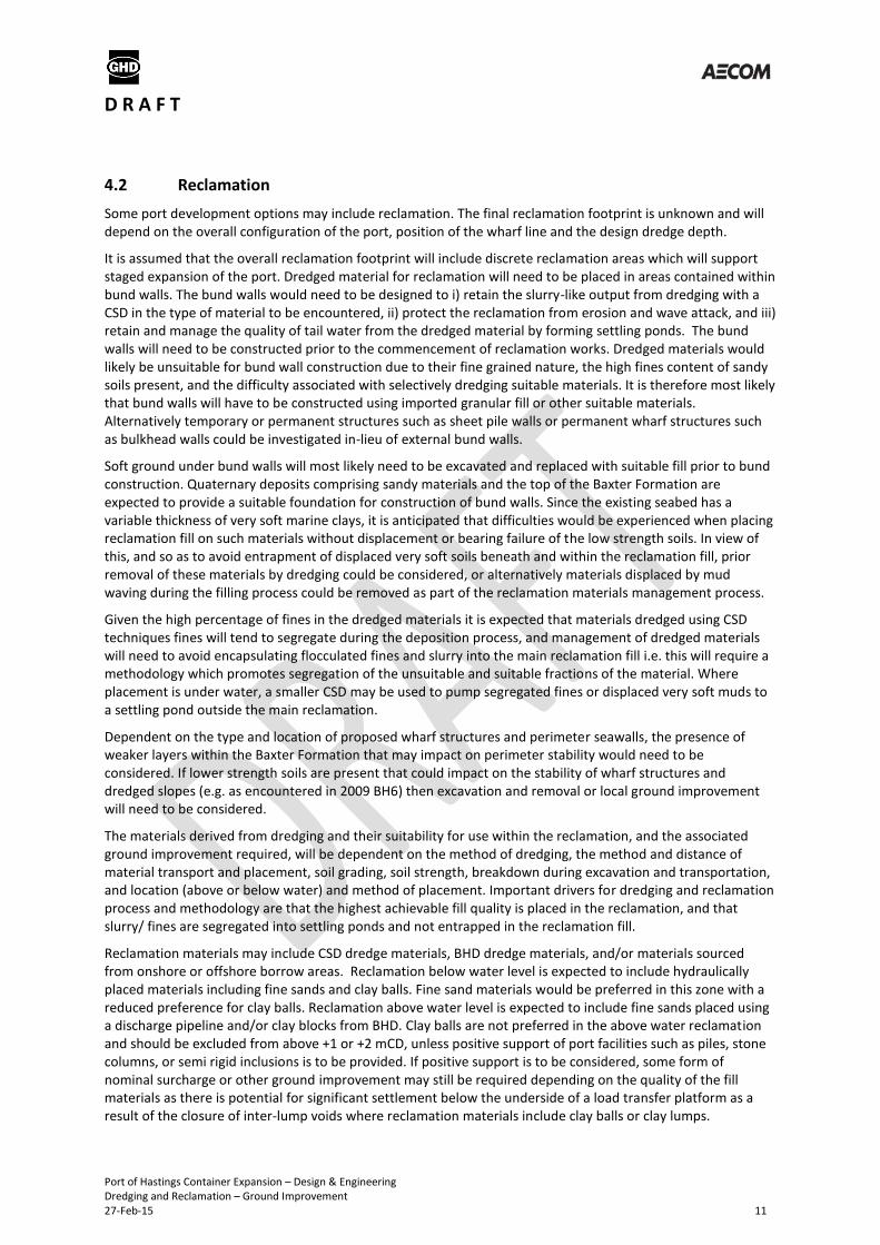
4.2 Reclamation
Some port development options may include reclamation. The final reclamation footprint is unknown and will depend on the overall configuration of the port, position of the wharf line and the design dredge depth.
It is assumed that the overall reclamation footprint will include discrete reclamation areas which will support staged expansion of the port. Dredged material for reclamation will need to be placed in areas contained within bund walls. The bund walls would need to be designed to i) retain the slurry-like output from dredging with a CSD in the type of material to be encountered, ii) protect the reclamation from erosion and wave attack, and iii) retain and manage the quality of tail water from the dredged material by forming settling ponds. The bund walls will need to be constructed prior to the commencement of reclamation works. Dredged materials would likely be unsuitable for bund wall construction due to their fine grained nature, the high fines content of sandy soils present, and the difficulty associated with selectively dredging suitable materials. It is therefore most likely that bund walls will have to be constructed using imported granular fill or other suitable materials. Alternatively temporary or permanent structures such as sheet pile walls or permanent wharf structures such as bulkhead walls could be investigated in-lieu of external bund walls.
Soft ground under bund walls will most likely need to be excavated and replaced with suitable fill prior to bund construction. Quaternary deposits comprising sandy materials and the top of the Baxter Formation are expected to provide a suitable foundation for construction of bund walls. Since the existing seabed has a variable thickness of very soft marine clays, it is anticipated that difficulties would be experienced when placing reclamation fill on such materials without displacement or bearing failure of the low strength soils. In view of this, and so as to avoid entrapment of displaced very soft soils beneath and within the reclamation fill, prior removal of these materials by dredging could be considered, or alternatively materials displaced by mud waving during the filling process could be removed as part of the reclamation materials management process.
Given the high percentage of fines in the dredged materials it is expected that materials dredged using CSD techniques fines will tend to segregate during the deposition process, and management of dredged materials will need to avoid encapsulating flocculated fines and slurry into the main reclamation fill i.e. this will require a methodology which promotes segregation of the unsuitable and suitable fractions of the material. Where placement is under water, a smaller CSD may be used to pump segregated fines or displaced very soft muds to a settling pond outside the main reclamation.
Dependent on the type and location of proposed wharf structures and perimeter seawalls, the presence of weaker layers within the Baxter Formation that may impact on perimeter stability would need to be considered. If lower strength soils are present that could impact on the stability of wharf structures and dredged slopes (e.g. as encountered in 2009 BH6) then excavation and removal or local ground improvement will need to be considered.
The materials derived from dredging and their suitability for use within the reclamation, and the associated ground improvement required, will be dependent on the method of dredging, the method and distance of material transport and placement, soil grading, soil strength, breakdown during excavation and transportation, and location (above or below water) and method of placement. Important drivers for dredging and reclamation process and methodology are that the highest achievable fill quality is placed in the reclamation, and that slurry/ fines are segregated into settling ponds and not entrapped in the reclamation fill.
Reclamation materials may include CSD dredge materials, BHD dredge materials, and/or materials sourced from onshore or offshore borrow areas. Reclamation below water level is expected to include hydraulically placed materials including fine sands and clay balls. Fine sand materials would be preferred in this zone with a reduced preference for clay balls. Reclamation above water level is expected to include fine sands placed using a discharge pipeline and/or clay blocks from BHD. Clay balls are not preferred in the above water reclamation and should be excluded from above +1 or +2 mCD, unless positive support of port facilities such as piles, stone columns, or semi rigid inclusions is to be provided. If positive support is to be considered, some form of nominal surcharge or other ground improvement may still be required depending on the quality of the fill materials as there is potential for significant settlement below the underside of a load transfer platform as a result of the closure of inter-lump voids where reclamation materials include clay balls or clay lumps.

D R A F T
Port of Hastings Container Expansion – Design & Engineering Dredging and Reclamation – Ground Improvement 27-Feb-15 12
4.3 Use of clay ball and clay lump fills (Singapore Experience)
It is anticipated that the proposed dredging will generate variable materials, the nature of which will be dependent on a number of factors as discussed in 4.2.
Based on the ground conditions in the port area, it is anticipated that dredging could generate the following materials:
Large lumps (> 1 m3) of clayey sand and clay if dredged using mechanical dredging equipment
Small clay balls of variable size mixed with sand and slurry from CSD operations
Silty fine sand from CSD operations
Clay and silt slurry from CSD derived from fluidisation of clayey and silty sands, and the erosion and breakdown of clay soils and clay balls as part of the CSD dredging and hydraulic transport processes
Ideally, fill for land reclamation, in particular fill placed in water, would comprise granular materials such as sand and gravel, since they are relatively easily placed and improved by densification. However, if it is proposed to use clay lumps and clay balls as reclamation fill, there are a number of important aspects that would need to be considered as part of the design and construction process.
Clay balls and clay lumps are increasingly being used as reclamation fill in Singapore as local sources of sand fill have been exhausted, and also due to the increasing cost of imported sand fill. This is of specific relevance to the Port of Hastings site due to the presence of stiff clays in the dredge area and the lack of clean sand fill.
Land reclamation in Singapore started in the 19th century. Initially soils excavated from inland hills and sand dredged from the surrounding seabed were used for reclamation. However, by the mid-1980s, the hill-cut soil and local dredged sand suitable for reclamation were almost exhausted (Ministry of Communications and Information, Singapore, 1986). Subsequent reclamations such as the Pulau Tekong Reclamation and the Tuas Reclamation were carried out mainly by filling with imported sand. Areas of land reclamation and the types of reclamation material are shown in Figure 4-1 and Figure 4-2. The increasing cost of imported sand and future reclamations having to deal with increasing water depths, greater than 10 meters and often to a depth of 20 meters, has led to the need for alternative fill materials for use in future reclamation. This has included reclamation using:
Layered sand and clay slurry derived from dredging of soft marine clays
Lumpy clay fill from mechanical grab dredging (> 1m3 lumps)
Clay balls from cutter suction dredging
Reclamation construction using the above material types has typically involved the construction of perimeter bunds using sand fill to confine the reclamation.

D R A F T
Port of Hastings Container Expansion – Design & Engineering Dredging and Reclamation – Ground Improvement 27-Feb-15 13
Figure 4-1 Land Reclamation in Singapore
Figure 4-2 Fill materials used in Singapore land reclamation projects (Ministry of Industry and communication, 1989)

D R A F T
Port of Hastings Container Expansion – Design & Engineering Dredging and Reclamation – Ground Improvement 27-Feb-15 14
Pre-load surcharge with vertical drains was commonly used for reclamations formed using dredged sand materials placed over soft marine clays. For example at Pasir Panjang Terminals 1 and 2, 335 hectares of land which was underlain by soft marine clay and reclaimed using 8-10m of imported sand was improved in the late 2000’s using vertical drains with fill surcharge.
Reclamation in Changi East involving the formation of 2000 Ha of land (Choa, 2000) using mostly hydraulically placed marine sand, used prefabricated vertical drains combined with surcharge to accelerate the consolidation settlement of the underlying soft compressible soil. Dynamic compaction, vibroflotation and Muller resonance compaction (MRC) were used to densify the granular fill; dynamic compaction being deployed where the depth of compaction was 5-7 m and vibroflotation and MRC methods where the required depth of compaction was 7-10m.
Where clay lumps have been used as reclamation fill, large settlements have been observed upon application of surcharge. This has been attributed to closing of inter-lump voids and plastic compression of the clay lumps (Karthikeyan 2004). Investigation of a reclamation created using large clay lumps (Punggol Timor Island) was undertaken 12 years after construction, to assess the present state of the reclaimed land with special emphasis on identifying the size of current inter-lump voids. The reclamation contained up to 8m thickness of large clay lumps overlain by 10m of sand fill. After 12 years the initially large inter lump voids were reduced to the size of intra lump voids, however the layer formed from clay lumps was still heterogeneous with variable engineering properties.
An overview of the factors affecting the nature and performance of lumpy clay and clay ball fill is given below, based on recent experience in Singapore (Robinson, 2005; Alapakam, 2006).
The properties of clay lumps and clay balls can vary considerably, and are dependent on many factors including initial soil strength and consistency, and moisture take up after dredging. Examples of clay lumps and clay balls are given in Figure 4-3 to Figure 4-5.
Figure 4-3 Formation of Clay Balls (Hydraulic Fill Manual, 2012)

D R A F T
Port of Hastings Container Expansion – Design & Engineering Dredging and Reclamation – Ground Improvement 27-Feb-15 15
Figure 4-4 Clay balls from Test Pit Excavations in the Old Tyabb Reclamation (Left)
Figure 4-5 Clay lumps dredged using large clamshell grab (Right)
For CSD dredging key factors influencing whether clay balls or slurry is produced, and resultant clay ball size, include i) soil plasticity, where lower plasticity soils occur they tend to break down and form a slurry more so than higher plasticity soils, ii) the size of the cutter head, and iii) the method and distance of transport whereby clay balls tend to reduce in size and break down to a slurry as pumping/ pipeline lengths increase.
Compressibility and total settlement under external loading differs between clay slurry and mixtures of clay slurry and clay balls or lumps as shown in Figure 4-6.
Figure 4-6 Compressibility curves in incremental tests (Mendoza and Hartlen, 1985)
Clay balls and clay lumps are characterised by a dual porosity or dual void ratio, comprising inter particle/lump voids (i.e. voids between the clay lumps) and intra particle/lump voids within the clay matrix of individual clay pieces. A schematic profile of land reclamation fill with clay lumps is given in Figure 4-7.

D R A F T
Port of Hastings Container Expansion – Design & Engineering Dredging and Reclamation – Ground Improvement 27-Feb-15 16
Figure 4-7 Schematic profile of land reclamation fill with clay lumps
Inter particle/lump voids are typically filled with slurry as shown in Figure 4-9 but may also be filled with water.
Figure 4-8 Large clay lumps (Left)
Figure 4-9 Clay lumps with inter-lump voids filled with slurry (Right)
After dredging and placement in water, clay balls and clay lumps will swell. The swelling process is influenced by the time delay between placement and subsequent ground improvement, and also the size of clay lumps or clay balls due to the difference in ratio of surface area to volume of clay. Small clay balls soften relatively quickly whereas softening of large clay lumps can take considerable time.
The swelling process results in reduction in strength of the clay material due to reduction in soil suction within the clay matrix and increase in volume due to moisture uptake. Swelling of clay lumps can result in disintegration of the clay and breakup of the material.
The rate of consolidation under external loading differs between non-swollen and swollen samples. Clays that have been subject to swelling and strength reduction tend to initially consolidate faster and inter lump voids close up at a lower applied load than for non-swollen materials.
The practical consequence of swell for large clay lumps when compared to smaller clay balls would be that clay balls will swell relatively quickly and form a more homogenous fill than large clay lumps. Large clay lumps may

D R A F T
Port of Hastings Container Expansion – Design & Engineering Dredging and Reclamation – Ground Improvement 27-Feb-15 17
require high surcharge loads to eliminate inter lump voids, as larger stronger lumps would transfer load through the intact clay matrix by arching rather than deforming to fill the voids.
If inter lump voids are not fully closed then the prediction of long term differential settlement becomes more difficult. A ground improvement process that effectively closes the large voids and consolidates the softened clay balls is therefore important to performance.
A common method of ground improvement of reclamation fill is to use preload surcharge. Vertical drains can be used to accelerate the surcharge process since consolidation of lumpy clay fill and clay balls can slow considerably once initial voids have closed up following loading.
Clay balls and clay lumps undergo significant and rapid initial settlement when initially loaded as inter particle voids close up, after which the rate and magnitude of settlement reduces, and mass permeability is reduced.
Inter lump void ratio within a reclamation fill profile will vary with depth, as materials at greater depth are subject to higher overburden pressure than shallower soils. Performance of clay ball or clay lump fill under pre-load surcharge will therefore vary both with time and with depth.
The pressure required to close up inter particle voids depends on soil strength of the parent material, and the level of swell. For softened clay balls pressure to close up inter particle voids can be in the order of 25 to 50 kPa, whereas for stronger lumps of clay surcharge pressure of over 100 kPa may be required.
Clay balls tend to provide a more homogenous fill once surcharged due to more uniform initial packing of the clay balls.
Typical test result curves which demonstrate initial rapid consolidation and reduction in void ratio due to closing up of inter lump voids are given in Figure 4-10. Rapid decreases in permeability with increasing consolidation pressure are also illustrated in Figure 4-10. The apparatus used for one-dimensional consolidation tests of lumpy clay and lumpy fill under a range of consolidation pressures is given in Figure 4-11 (Alapakam, 2006).

D R A F T
Port of Hastings Container Expansion – Design & Engineering Dredging and Reclamation – Ground Improvement 27-Feb-15 18
Figure 4-10 Typical e-log p and permeability curves for lumpy fill consolidation experiments

D R A F T
Port of Hastings Container Expansion – Design & Engineering Dredging and Reclamation – Ground Improvement 27-Feb-15 19
Figure 4-11 Consolidation tests of lumpy clay fill
Strength profiles from cone tests on consolidated clay lumps indicate variable shear strength at low consolidation pressures (overburden of 50 and 100 kPa), becoming more uniform at higher consolidation pressures as can be seen in Figure 4-12. The practical consequence of this is that shear strength of clays subject to typical levels of preload surcharge (< 100 kPa) would be variable, and the strength would still be relatively low. This would mean that a significant thickness of engineered fill would need to be provided above pre-load surcharged lumpy clay, to provide suitable support and adequate bearing capacity for subsequent use, in a similar manner to what would be required to support surface loading on pre-load surcharged normally consolidated marine clays.

D R A F T
Port of Hastings Container Expansion – Design & Engineering Dredging and Reclamation – Ground Improvement 27-Feb-15 20
Figure 4-12 Shear strength profiles obtained from cone penetration tests for lumpy clay
4.4 Placement Methods and Reclamation Materials
Possible placement methods are given in Table 4-1 and the range of potential reclamation materials are given in Table 4-2.
Placement Under Water Placement Above Water
Bottom dumping by TSHD and / or barges
Placement via the discharge pipeline of a cutter suction dredger or TSHD
Pumping through a spreader or diffuser at the end of a discharge pipeline from a CSD and / or TSHD
Placement of mechanically dredged materials by truck or other means, followed by spreading and compaction
Dumping by barge or placing by grab
Placement of land sourced borrow materials by truck or other means followed by spreading and compaction
Rainbowing by TSHD Rainbowing by TSHD
Table 4-1 Placement methods for dredged materials

D R A F T
Port of Hastings Container Expansion – Design & Engineering Dredging and Reclamation – Ground Improvement 27-Feb-15 21
Material Composition/type Potential Use/Location Placement Method
1 Imported sand and/ or quarry product Perimeter bund walls Replacement of unsuitable founding materials at seawalls and wharf structures Backfill behind wharf structures
Hydraulically and/or mechanically placed above and below mean sea level
2 Fine sand from Baxter and Sherwood Formation from CSD
General reclamation fill below or above water
Hydraulically placed above and below mean sea level Fluidised fines to be removed
3 Clay balls from Baxter and Sherwood Formation from CSD
General reclamation fill below water Avoid clay balls in upper part of reclamation fill due to low strength and poor subgrade support, unless positive structure support used (e.g. CMCs or piles)
Hydraulically placed below mean sea level Fluidised fines to be removed
4 Mechanically dredged clayey or silty sands from the Baxter and Sherwood Formation
General reclamation fill below and above water
Mechanically placed and compacted above mean sea level
5 Mechanically dredged clay lumps/blocks from the Baxter and Sherwood Formation
General reclamation fill above water
Mechanically placed and compacted above mean sea level
6 Mechanically dredged clay lumps/blocks from the Baxter and Sherwood Formation
General reclamation fill below water
Mechanically placed below mean sea level and ground improved
7 Mechanically excavated clayey or silty sands, or silty/ sandy clays derived from terrestrial Baxter and Sherwood Formation
General reclamation fill above water
Mechanically placed and compacted above mean sea level.
8 Mechanically excavated silty/ sandy clays derived from terrestrial Baxter and Sherwood Formation
General reclamation fill below water placed as clay lumps
Possible advancement by pushing forwards from land and ground improved
9 Dredged Quaternary marine deposits Clays unlikely to be suitable as general reclamation fill
-
10 Fluidised fines from Baxter and Sherwood Formation
DMM Material (i.e. Disposal only) / Settling Ponds
-
11 Fluidised fines from Quaternary marine deposits
DMM Material (i.e. Disposal only) / Settling Ponds
-
Table 4-2 Reclamation materials and potential use and placement method

D R A F T
Port of Hastings Container Expansion – Design & Engineering Dredging and Reclamation – Ground Improvement 27-Feb-15 22
5.0 Ground Improvement Requirements
Following reclamation, it is anticipated that ground improvement works will need to be undertaken to provide adequate support for structures, pavements, services and general infrastructure; to reduce post construction settlement; and mitigate against liquefaction. The exact nature and scope of ground improvement works would be dependent on a number of considerations including:
Methods of dredging and reclamation
Actual materials that are to be dredged and used as reclamation fill
Time available to carry out the ground improvement works
The level and distribution of live loading
Construction staging
The sensitivity of specific facilities or operations to differential settlement
Preference by owners and/ or operators for maintenance and or repair of facilities
Technical and economic merits of ground improvement options.
Ground improvement strategies will vary across the terminal area and are expected to be a function of the considerations listed above. The terminal area will include the following areas each with their own loading criteria, equipment tolerances, and sensitivity to settlement.
Wharf structure and operational area
Container stack areas
Container handing equipment (ASCs, RTGs)
Terminal roads
Rail corridors
Ancillary structures and facilities.
For example, the ASC stacks may be more sensitive to differential settlement and may experience higher loading requiring more intensive ground improvement compared to other areas, whereas road and rail corridors may be located on minimal depths of reclamation fill, and may be less sensitive to differential settlement and more easily maintained and therefore require less intensive ground improvement.
The Basis of Design states that settlement shall be limited in keeping with the operational tolerances associated with the intended land-use. Tolerances for terminal operations will depend on the mode of operation and area and shall be confirmed based on the terminal systems studies which are currently underway.
Typical performance requirements are given in Table 5-1and Table 5-2 which provide indicative/order of magnitude settlement criteria expected for the terminal area.
Settlement Type/ Area Performance Criteria
Total settlement Less than 50 mm in 2 years
Total settlement Less than 300 mm in 20 years
Differential settlement Less than 1:200
Container exchange area Maximum gradient 1% longitudinal and 0.5% transverse
Differential gradient between RTG Beams 1.5% with maximum differential along beams of 1:200
Table 5-1 Typical Performance Requirements

D R A F T
Port of Hastings Container Expansion – Design & Engineering Dredging and Reclamation – Ground Improvement 27-Feb-15 23
ISO 12488 (Cranes - Tolerances for wheels and travel and traversing tracks) - ASC rail tolerance (trigger for maintenance)
Description Class 3 Class 4
Rail Gauge +/- 28 mm +/- 43 mm
Horizontal Straightness +/- 40 mm +/- 80 mm
Differential Settlement +/- 40 mm +/- 80 mm
Table 5-2 ASC Rail Tolerance
It is noted that the in situ Baxter Formation soils beneath the port area are generally relatively competent. Extensive ground improvement of these materials is unlikely to be required. However, local lower strength strata have been identified within the Baxter Formation at some locations, which if present beneath perimeter bunds, or at locations of critical or settlement sensitive structures, may mean that some form of ground improvement is required.

D R A F T
Port of Hastings Container Expansion – Design & Engineering Dredging and Reclamation – Ground Improvement 27-Feb-15 24
6.0 Ground Improvement Techniques
There are numerous techniques that can be used to improve the properties of the ground where sites are underlain by soft or loose natural soils or reclamation fills. Many of the available ground improvement techniques are implemented by specialist ground improvement contractors, some using proprietary equipment. Other techniques simply involve adding fill to a site to pre-load the ground to a level in excess of anticipated post construction loading, and then allowing the ground to consolidate.
Several commonly used ground improvement options that may be appropriate for the proposed site are described below, together with a brief commentary on where such options may be applicable.
Actual ground improvement methods will depend on ground conditions, design and performance requirements, time available, cost of ground improvement works, and the type of structure or facilities being constructed. It is common on sites of this scale that a combination of ground improvement techniques would be considered for different loading scenarios and performance requirements. For example ground improvement methods to treat reclaimed sand fill and underlying soft estuarine sediments for the recently completed coal export facilities in Newcastle, NSW included several ground improvement methods as listed below (Chau, 2008, Hawkins, 2008, Jones, 2008).
Impact rolling (rail loop)
Wick drains + geosynthetic basal reinforcement (rail loop)
Geosynthetic basal reinforcement + light weight fill (rail loop)
Dynamic replacement (coal stockyard)
Vibroreplacement/Stone columns (stacker berm).
Notwithstanding the above, common methods of ground improvement that may be appropriate for the proposed Port of Hastings site include:
Excavation and replacement
Displacement or mud-waving
Preload surcharge with or without vertical drains
Vacuum consolidation
Vibroflotation or vibrocompaction
Vibroreplacement – for example stone columns or sand columns
Dynamic compaction
Dynamic replacement
Deep soil mixing
Jet grouting
Semi rigid inclusions
Impact rolling
Deep foundations or piling.

D R A F T
Port of Hastings Container Expansion – Design & Engineering Dredging and Reclamation – Ground Improvement 27-Feb-15 25
6.1 Soil Removal and Replacement
Soil replacement involves the total removal and replacement of the existing soil and is one of the simplest methods to improve the subsoil. Unsuitable materials are replaced with better quality fill materials. Soil removal and replacement is usually performed with conventional earth-moving equipment or dredging equipment.
Soil removal and replacement requires transport and disposal of the removed material. If the soil cannot be recycled as a construction material in the fill itself or disposed of at a nearby location, the costs of removal can be significant.
Soft ground under bund walls will most likely need to be excavated and replaced with suitable fill prior to bund construction. Removal of soft Quaternary deposits below the reclamation pad may also be considered prior to the placement of reclamation materials. Removal of Baxter Formation soils and replacement with rockfill may be undertaken along the quay line to provide a base with adequate bearing capacity and to minimise differential settlement for gravity wall type quay structures, should gravity structures be considered feasible.
6.2 Soil Displacement or Mud-waving
Soil displacement involves the displacement of unsuitable materials which are replaced with better quality fill material. Displacement of unsuitable soils can be completed by using fill materials to cause a bearing capacity failure in low strength soils resulting in penetration of the fill material and lateral displacement of the low strength materials, or formation of a ‘mud wave’ in front of the reclamation. The displaced materials can be progressively removed along the reclamation front.
Soil displacement may be applicable where placing reclamation fill on low strength Quaternary deposits. There is a risk that the displaced materials become entrapped in the reclamation fill or that the low strength materials are only partially displaced. If soil displacement and removal is to be considered this would need to be carefully managed.
6.3 Pre-load Surcharge with or without Vertical Drains
Pre-load surcharge involves placement of fill above the reclamation platform up to a level where pre-loading is in excess of final loading. Once the pre-load is placed the area is allowed to consolidate.
In granular materials settlement is rapid as porewater can readily escape from the soil as load is placed. However, where fill is placed over thick deposits of soft clay, settlement can continue for considerable time (years) due to slow drainage of excess pore water pressures. Installation of vertical drains typically at 1 to 2 m centres shortens the drainage path for excess pore water, accelerating the consolidation process and hence the settlement rate. The drainage paths with and without vertical drains for an embankment placed on slow draining soil are shown in Figure 6-1. Vertical drains may comprise prefabricated band drains or wick drains or bored columns filled with sand and are usually installed on a triangular grid pattern. The drains must be able to discharge the extracted pore water into a free-draining medium usually located at the top of the vertical drain. Installation of prefabricated vertical drains is commonly carried out on land using specialist installation rigs and can also be installed over water using floating pontoons or barges. The installation process over water is however slower than drains installed on land (Hydraulic Fill Manual, 2012).Figure 6-2 shows drain installation and extracted pore water escaping at top of drain. Figure 6-3 shows a schematic of pre-load surcharge with vertical drains.
Preload surcharge may be a suitable ground improvement technique to consolidate and strengthen soft and loose fills and underlying intertidal sediments in the Old Tyabb reclamation. Based on typical magnitude of port loading (40 to 60 kPa) the thickness of pre-load surcharge needed may be in the order of 3 to 4 m.
Since soft clay deposits beneath the Old Tyabb reclamation appear to be relatively thin and sandy layers are present, it may be feasible to implement a “rolling” pre-load surcharge regime without the need for vertical drains if time permits.
Pre-load surcharge may also be used to consolidate clay balls or lumpy clay fills should such materials be considered as reclamation fill. Following initial rapid settlement reduced permeability may necessitate vertical

D R A F T
Port of Hastings Container Expansion – Design & Engineering Dredging and Reclamation – Ground Improvement 27-Feb-15 26
drain installation to speed the pre-load surcharge process, depending on time available and actual rate of the consolidation.
Figure 6-1 Drainage paths with and without vertical drains
Figure 6-2 Drain Installation on land and extracted pore water escaping at top of drain (Hydraulic Fill Manual 2012)

D R A F T
Port of Hastings Container Expansion – Design & Engineering Dredging and Reclamation – Ground Improvement 27-Feb-15 27
Figure 6-3 – Schematic of pre-load surcharge with vertical drains
6.4 Vacuum Consolidation
An alternative form of applying surcharge loading to an area is vacuum consolidation. This involves placing an airtight membrane over the surface to be treated and applying a vacuum. This can generate a preload of up to a theoretical maximum of 100kPa (equivalent to a 5m high embankment) but in practice this value will be less as a result of losses in the system.
The vacuum loading is generated by electric pumps removing water from a surface drainage layer connected to vertical wick drains. This accelerates the rate of consolidation of the soft clay significantly. Figure 6-4 shows a schematic of vacuum consolidation.
One of the advantages of this method over traditional surcharge methods is that it exerts an isotropic load without introducing shear stresses in the subsoil and therefore can be used where traditional surcharge is not possible for edge stability reasons.
Vacuum consolidation may be used to accelerate the rate of consolidation of soft clay or silty clay layers, and may be used in combination with pre-load surcharge. In sands or sandy clays cut-off walls into non-permeable layers may be required to seal off the vacuum, which may not be feasible in Baxter or Sherwood Formation soils due to the interbedding of sand, silt and clay layers and the lateral variability of these materials.
Over the past decade, the application of vacuum consolidation for stabilising soft coastal clay and other low-lying estuarine soils has become popular in Australia (Indraratna, 2011). Vacuum consolidation has been recently used in combination with conventional preload surcharge with vertical drains by Port of Brisbane on reclamation of sub-tidal land at Fisherman Islands as shown in Figure 6.5. This site is more suited to the use of vacuum consolidation compared to the Port of Hastings site as the soil profile, which comprises an upper sand layer 2-3m thick underlain by a highly compressible low strength Holocene clay layer having a thickness from 6 to 25m, can provide an effective seal required for the vacuum process. Dredged materials were placed up to a thickness of 4m.

D R A F T
Port of Hastings Container Expansion – Design & Engineering Dredging and Reclamation – Ground Improvement 27-Feb-15 28
Figure 6-4 Schematic of vacuum consolidation
Figure 6-5 Vacuum consolidation at Port of Brisbane, 1.5 Ha trial (left), 9.3 Ha production area (right) (Menard Bachy)
6.5 Vibroflotation
Vibroflotation or vibrocompaction involves the use of a vibrating probe that can penetrate granular soil to depths of over 30 metres (see Figure 6-6 – Schematic of vibroreplacement process). The vibrations of the probe cause the grain structure to collapse thereby densifying the soil surrounding the probe. In order to effectively treat and densify a loose soil, the vibroflot is raised and lowered in a grid pattern.
Vibroreplacement is a combination of vibroflotation with the introduction of a gravel backfill, resulting in stone columns, or sand backfill resulting in sand columns. This increases the amount of densification, provides a degree of reinforcement to weaker soils, and can potentially provide an effective means of drainage. Vibroreplacement can also be used to improve the strength of softer cohesive materials whereby granular columns are installed at suitably close centres to reinforce these materials. This method is not suited in very soft soils which have a very low undrained shear strength since the lateral support for the stone columns may be insufficient.
The range of soils for which the vibroflotation method is suitable is given in Figure 6-7 which indicates performance in medium and coarse sand and fine and medium gravel deposits. However, vibroflotation may not be suitable in fine sands and in soils with more than 10 to 20% silt and clay content. Since granular Baxter Formation soils comprise fine sands, often with a relatively high fines content, depending on the resultant particle size distribution after reclamation filling, the ability to densify reclamation sands derived from the Baxter Formation using vibroflotation may be marginal.

D R A F T
Port of Hastings Container Expansion – Design & Engineering Dredging and Reclamation – Ground Improvement 27-Feb-15 29
In circumstances where imported granular fills are to be considered for the Hastings project, such as for perimeter bunds, or as general reclamation fill, then depending on the particle size distribution of the materials vibrocompaction may be an appropriate method of densifying loose sands.
High performance areas (around quay structures) of the 60 hectare reclamation completed as part of the Port Botany expansion were treated using land and marine based vibrocompaction methods.
Figure 6-6 – Schematic of vibroreplacement process
Figure 6-7 Field of application for vibro methods
6.6 Dynamic Compaction
Densification by dynamic compaction is performed by dropping a heavy weight of steel or concrete in a grid pattern from heights of 10 to 30 m. It can provide an economical way of improving soil for mitigation of liquefaction hazards and strengthening shallow weaker soils. Local liquefaction can be initiated beneath the drop point making it easier for the sand grains to densify. As can be seen from Figure 6-8 the process is invasive, and the surface of the soil would require compaction with addition of granular fill following dynamic compaction. Dynamic compaction is usually completed using land based equipment but can be completed using marine based equipment as shown in Figure 6-9.
The effective depth of dynamic compaction is dependent on the nature of materials to be compacted, and the height, weight, and spacing of drop, and would be subject to site trials. Typical effective depths would be in the

D R A F T
Port of Hastings Container Expansion – Design & Engineering Dredging and Reclamation – Ground Improvement 27-Feb-15 30
order of 5 to 10 m in granular soils, up to around 5 m in cohesive soils, but may be ineffective in very soft and soft clays.
Dynamic compaction could be suitable for densification and compaction of dredged granular materials in the main reclamation area, and (possibly in conjunction with dynamic replacement techniques) the existing fills in the Old Tyabb reclamation and the underlying loose intertidal sediments. However, dynamic compaction may not be fully effective in improving fills and sediments where they have significant clay content, particularly at depth.
Dynamic compaction was also used to improve areas of the Port Botany reclamation using a 25t dynamic compaction weight dropped from a height of 23m.
Figure 6-8 - Dynamic compaction
Figure 6-9 Offshore dynamic compaction and replacement in Singapore - Pasir Panjang Terminal 3 & 4 at 30m below water (Menard)

D R A F T
Port of Hastings Container Expansion – Design & Engineering Dredging and Reclamation – Ground Improvement 27-Feb-15 31
6.7 Dynamic Replacement
Dynamic replacement is a similar process to dynamic compaction and involves delivering impact energy to the ground by means of dropping a large mass from height while the craters created by the impact of the heavy weight are backfilled with granular fill during the process as shown in Figure 6-10. The resulting stone columns are significantly larger in diameter, have higher load carrying capacity, are more rapid to install, and hence more economical compared with the conventional stone column ground treatment method (vibroreplacement). The disadvantage of dynamic replacement, however, is that there is a limiting depth to which the dynamic replacement stone columns can be installed, and at which the granular fill near the top of the columns will tend to heave rather than being pushed downwards by the falling weight (Wong, 2004). This technique is used to improve cohesive soils to depths of up to 5 to7 m and may be suitable for improvement of shallow cohesive soils such as the Old Tyabb reclamation.
Dynamic replacement was recently used for treatment of a reclaimed coal stockpile area at Kooragang Island, NSW. This is believed to be the largest dynamic replacement project completed in the southern hemisphere (Chau, 2008) where dynamic replacement was used to improve an upper soft soil layer to nominal depths of 6m. This ground improvement method was selected in lieu of the original ground improvement method of progressive preloading of the site using dredged sands due to programme constraints and limited availability of dredged sand material.
Figure 6-10 - Dynamic replacement (Menard Bachy)
6.8 Deep Soil Mixing
Deep soil mixing (DSM) involves in-situ mixing of soil with admixtures which chemically react with the soil to increase strength and stiffness, and reduce permeability and compressibility. The stabilising additives are injected into the soil in dry or slurry form through hollow rotating mixing shafts tipped with various cutting and mixing tools, resulting in the formation of stiff columns within the soil. The method can be used in stratified soils including sands, soft clays and silts and can be applied up to depths of 50 m.

D R A F T
Port of Hastings Container Expansion – Design & Engineering Dredging and Reclamation – Ground Improvement 27-Feb-15 32
Deep soil mixing could be suitable for improvement of dredged materials in the main reclamation area, existing reclamation fills in the Old Tyabb reclamation and possibly the underlying loose intertidal sediments.
Deep soil mixing has the benefit of not extracting soils, however depending on the adopted method some spoil may be generated during the mixing process which would need to be disposed of. This method can comprise single columns or multiple installations forming walls, blocks, or grids to improve the ground and support specific facilities as illustrated in Figure 6-11. Depending on the column patterns a load transfer platform may be required at surface to transfer load to the columns using crushed rock and high strength geotextile or geogrid.
Deep soil mixing could be suitable for improvement for a number of applications including improvement of dredged materials in the main reclamation area, providing soil reinforcement behind wharf structures, and for improvement of the existing reclamation fills and underlying loose sediments in the Old Tyabb reclamation.
Figure 6-11 Examples of deep soil mixing equipment and column patterns
6.9 Jet Grouting
Jet grouting differs from injection or permeation grouting of fractured or permeable soils and is a method of ground improvement that uses high energy in the form of a high velocity jet of grout to mix cement grout into the in-situ soil, forming grouted panels or columns and resulting in a significant increase in the strength of the treated soil, and reducing the permeability of the soil.
The method involves drilling a hole to the design depth of the treatment, whilst maintaining an annular space around the drill string to facilitate return flow. Grout at high pressure is pumped to the bottom of the drill

D R A F T
Port of Hastings Container Expansion – Design & Engineering Dredging and Reclamation – Ground Improvement 27-Feb-15 33
string where it emerges though a very small diameter orifice, converting the energy from high pressure to very high velocity. To form columns of treated ground, the drill string is rotated as the hydrodynamic jet of grout erodes and disintegrates the soil and mixes into it.
The soil type and stratigraphy influence the quality of the grouted soil column (soilcrete) and the geometry of erosion. Cohesionless soils are readily eroded with this method. However for cohesive soils, as plasticity and stiffness increase, erodibility decreases to a point where jet grouting may not effectively erode stiff cohesive soils (Kirsch and Bell, 2013). Stratification and variable soil conditions can lead to variable soilcrete quality.
The installation process for jet grouted columns, range of applicable soil types and indicative strength are given in Figure 6-12.
Figure 6-12 Installation process for jet grouted columns, range of applicable soil types and indicative strength (Menard Bachy)
6.10 Semi Rigid Inclusions
Semi rigid inclusions such as controlled modulus columns (CMCs) can be used to strengthen the ground by installation of concrete or grout using a displacement auger which displaces the soil laterally with practically no spoil or vibration to form a cylindrical cavity, with the concrete or grout mix pumped in during auger extraction.
Unlike stone columns/vibroreplacement whose stability relies on the horizontal confinement of the soil, or deep soil mixing where column strength is dependent on the in-situ soil’s properties, CMC’s do not rely on external parameters for lateral stability nor are column strengths affected by the surrounding soil. Thus this method can reduce settlements more efficiently compared to other techniques in which inclusions are installed in the soil.
Where CMCs are used to support specific facilities this typically requires a load transfer platform at surface to transfer load to the CMCs using crushed rock and high strength geotextile or geogrid. CMCs can be reinforced and used as displacement piles to support structural loads or to resist bending. It is understood that CMCs are currently being installed at the Webb Dock East Container Terminal, Port of Melbourne
Semi rigid inclusions could be suitable for improvement of dredged materials in the main reclamation area, existing reclamation fills in the Old Tyabb reclamation and possibly the underlying loose intertidal sediments.

D R A F T
Port of Hastings Container Expansion – Design & Engineering Dredging and Reclamation – Ground Improvement 27-Feb-15 34
Figure 6-13 Installation process for CMCs (Menard Bachy)
6.11 Impact Rolling
Impact rolling involves the use of a non-circular roller to impart a high level of energy into the ground when towed at relatively high speed (10 to 12 km/hr). A number of proprietary 3, 4, or 5 sided rollers are available on the market (see Figure 6-14). The benefit of impact rolling is that it can improve ground to a greater depth than compaction with conventional earthworks equipment, with reported depths of influence of up to 4 m, but with 2 m being more typical.
Impact rolling is unlikely to be suitable for improving deeper uncontrolled fills, and is not suitable for soft sediments. However, impact rolling could be effective in compacting the Old Tyabb reclamation fill, in conjunction with pre-load surcharging, as a preparatory treatment of the exiting fill platform for pavement support.
Impact rolling was used for treatment of a 2200 hectare reclamation at the New International Airport, Doha, Qatar, which was reclaimed using dredged sand materials and improved using impact rolling close to the water level and again at 3m above water level. Impact rolling was also used extensively for treatment of the upper reclamation materials at the Port Botany reclamation.
Figure 6-14 - High Energy Impact Rolling using a 3 sided roller (LandPac)

D R A F T
Port of Hastings Container Expansion – Design & Engineering Dredging and Reclamation – Ground Improvement 27-Feb-15 35
6.12 Deep Foundations or Piling
Deep foundations or piling may be used to transfer load from surface structures and port related facilities to deeper competent strata. Bored or driven piles would be suitable for such use. The use of piles would reduce the need for extensive ground improvement, although it would be necessary to consider background settlement of reclamation soils beneath the piled structures, which would result in negative skin friction, and differential settlement between piled and non-piled areas.
Deep foundations or piling may be suitable for supporting specific structures such as ASC rails and container stacks in the main reclamation areas and could be used in conjunction with other ground improvement methods.

D R A F T
Port of Hastings Container Expansion – Design & Engineering Dredging and Reclamation – Ground Improvement 27-Feb-15 36
7.0 Ground Improvement Overview
An overview of the ground improvement techniques relevant to the Port of Hastings is given in Table 7-1.

D R A F T
Port of Hastings Container Expansion – Design & Engineering Dredging and Reclamation – Ground Improvement 27-Feb-15 37
Ground Improvement Method Advantages Disadvantages Applicable Areas
1 Excavation and replacement
All unsuitable material removed – no risk of material
becoming entrapped in reclamation fill
No ground improvement required for removed material
No ongoing creep settlement of removed materials
Cost will depend on location, water depth, and thickness of
materials to be removed
May be more expensive than ground improvement treatment
Requires disposal of unsuitable materials
Suitable for improvement of soft soils under permanent bund walls and
soft soils along wharf alignments (depending on form of wharf structure)
2 Displacement or mud-waving
Cost-effective alternative to excavation and replacement
No additional ground improvement required if mud wave
removed or located outside work area
No ongoing creep settlement (assuming all unsuitable
materials are removed)
Requires disposal of unsuitable materials
Requires relatively high differential fill level to displace other
than surficial very soft recent marine muds. May not be
effective in hydraulically placed sands
Risk of unsuitable materials becoming entrapped beneath or
within the reclamation fill
Risk that unsuitable materials are only partially displaced – full
depth of material not displaced
May need to undertake ground improvement of residual weak
soils
Difficult to monitor and verify during filling operations
Suitable for very soft recently flocculated marine clay/ muds with careful
management
Not recommended in settlement sensitive or in critical areas due to high
risk of entrapment of unsuitable materials
3 Preload surcharge Rapid settlement in granular materials Slow settlement where fill is placed over soft clays or where fill
includes cohesive materials
Surcharge required to be in place for several months. Without
improved drainage surcharge may need to be in place for many
years in cohesive soils
Surcharge loading may result in edge instability
Requires fill source for pre-load surcharge
Only suitable for densification and compaction of sands placed over the
main reclamation area. Dredged materials are expected to comprise
clayey sand and clay and silt materials – therefore not considered suitable
without vertical drains
(Not suitable for hydraulically placed sand in perimeter bund/ seawall
unless reclamation extended offshore and then trimmed back)
4 Preload surcharge with vertical drains
Rate of consolidation can be rapidly accelerated - decreases
overall time required for primary consolidation in cohesive
soils compared to preload surcharge
Relatively low cost to install drains
Requires specialist equipment for installation of vertical drains
Requires stable platform for installation equipment
Surcharge loading may result in edge instability
May take 6 to 12 months for settlement to occur
Requires fill source for pre-load surcharge
Suitable for improvement of dredged materials placed over main
reclamation area, and lower soft / loose fills in Old Tyabb reclamation
5 Vacuum consolidation
Does not require temporary surcharge materials
Shorter construction period compared to other preload
methods
Exerts an isotropic load without introducing shear stresses in
the subsoil and therefore does not affect the stability of soft
strata
Maximum theoretical preload is 100kPa- actual preload is
limited to around 70 to 80kPa
Difficult to form an effective seal in sandy soils – requires
extensive cut-off walls into non-permeable layers
May be difficult to seal permeable base
May not be suitable due to the difficultly associated with forming an
effective seal in Baxter Formation materials
6 Vibroflotation or vibrocompaction
Can penetrate granular soils to depths of 30m
Cost-effective alternative to other ground improvement
techniques for granular soils
Effective above and below water level
Can be completed using land or water based equipment
Not suitable for use in fine sands and soils containing more than
10-20% fines content
Requires a stable working platform
Requires specialist equipment– high mobilisation costs
Not suitable for cohesive soils
Suitable for densification and compaction of sands placed over main
reclamation platform, hydraulically placed sand in perimeter bund /
seawall (over water operation)
For reclamation platform effectiveness may be limited/marginal due to
the high fines content of Baxter Formation soils
7 Vibroreplacement - Stone columns or sand columns
Can penetrate granular soils to depths of 30m Not suited to very soft soils which cannot provide sufficient Suitable for improvement of soft clays and loose sands soils beneath

D R A F T
Port of Hastings Container Expansion – Design & Engineering Dredging and Reclamation – Ground Improvement 27-Feb-15 38
Ground Improvement Method Advantages Disadvantages Applicable Areas
Can be used in fine sands and cohesive soils
lateral support for the stone columns
Requires a stable working platform
Requires specialist equipment– high mobilisation costs
May require load transfer platform
reclamation platform
May be suitable alternative to preload surcharge or other methods for
main reclamation fill with load transfer platform
8 Dynamic compaction
Uses standard construction equipment
Economical
High production rate compared to other ground
improvement techniques
High energy and vibrations may have impact on nearby
structures
Effective depth limited to 5-10m in granular soils and around 5m
in cohesive soils
May be ineffective in very soft and soft soils, or soils with
significant clay content
Requires a stable working platform
The surface of the soil may require shallow compaction with
possible addition of granular fill following dynamic compaction
Suitable for improvement of dredged granular soils in areas of limited
reclamation fill thickness
Possible use to improve the existing fills in the Old Tyabb reclamation and
underlying loose intertidal sediments, although may need addition of
granular fill i.e. dynamic replacement
9 Dynamic replacement
Can be used in stratified soils including very soft to soft soils
High production rate compared to other ground
improvement techniques
High energy and vibrations may have impact on nearby
structures
Effective depth limited to 5-10m in granular soils and around 5m
in cohesive soils
Requires a stable working platform
Suitable for improvement of shallow cohesive soils such as the Old Tyabb
reclamation and areas with limited reclamation fill thickness
10 Deep Soil Mixing
Applicable up to depths of 50m
Can be used in stratified soils including very soft to soft soils
Spacing and patterns of DSM elements highly flexible,
arrangements tailored to specific needs
High productivity usually possible (hence, economical) for
large-scale projects
Engineering properties of treated soil can be closely
designed
Causes minimal lateral or vertical stress that could
potentially damage adjacent structures
No vibration, medium-low noise
May generate very low volume of spoil (dry method,
trenchers)
Quality of treatment verifiable during construction
Requires specialist equipment – high mobilisation costs for
mixing and batching equipment
Dense cohesionless soils can be difficult to penetrate
May generate significant volume of spoil depending on mixing
method (wet method)
Requires a stable working platform - weight of the equipment
may be problematic for weak soils (depending on the method)
Limited ability to treat isolated strata at depth
Suitable for improvement of dredged materials in the main reclamation
and existing reclamation fills in the Old Tyabb reclamation and the
underlying loose intertidal sediments
May be suitable for ground improvement of perimeter bunds or fill in
close proximity to structures
11 Jet grouting
Can be used in stratified soils including very soft to soft soils
Spacing and patterns of grouted elements highly flexible,
arrangements tailored to specific needs
Engineering properties of treated soil can be closely
designed
Effective depth limited to 15-20m
Requires specialist equipment – high mobilisation costs for
mixing and batching equipment
Possibly suitable for local areas of ground improvement but other
methods likely to be more suited for large areas of ground improvement.
12 Semi rigid inclusions
Applicable up to depths of around 35m
Can be used in stratified soils including very soft to soft soils
Displacement technique generates very little spoil
Spacing and patterns of semi rigid inclusions is highly
flexible, arrangements tailored to specific needs
Engineering properties of semi rigid inclusions can be closely
Requires specialist equipment – high mobilisation costs for
mixing and batching equipment
Requires a stable working platform
Suitable for improvement of dredged materials in the main reclamation
and existing reclamation fills in the Old Tyabb reclamation and possibly
the underlying loose intertidal sediment.

D R A F T
Port of Hastings Container Expansion – Design & Engineering Dredging and Reclamation – Ground Improvement 27-Feb-15 39
Ground Improvement Method Advantages Disadvantages Applicable Areas
designed
Can be relatively cost effective due to speed of installation
Can be reinforced and used as displacement piles
13 Impact Rolling Can improve ground to a greater depth than compaction
with conventional earthworks equipment
Depth of influence limited to a maximum of around 4m but
more typically around 2m
Unsuitable for soft soils
Unsuitable for deeper uncontrolled fills
Suitable for compaction of shallow sand placed over main reclamation
platform, and for surface preparation of near surface fill in Old Tyabb
reclamation
May be used in conjunction with other methods
14 Deep foundations or piling
Applicable up to depths of around 50m
Can be used in stratified soils including very soft to soft soils
Uses common design and construction methods and
equipment
Engineering properties of piled foundations can be closely
designed
Spacing and patterns of piles is highly flexible, and allows
arrangements to be tailored to specific needs
Pile set out can be varied to suit ground conditions and
loading requirements
Can achieve high load capacity
Potential differential settlement between piled and non-piled
areas
Not expected to be economical over large areas compared to
other methods
Limited flexibility to accommodate future changes to layout,
loading use
Suitable for supporting facilities on dredged materials in the main
reclamation and existing reclamation fills in the Old Tyabb reclamation.
However likely to be expensive compared to other options
Table 7-1 Overview of Ground Improvement Techniques

D R A F T
Port of Hastings Development Project – Design and Engineering Dredging and Reclamation – Ground Improvement 27-Feb-15 40
Ground improvement techniques that are likely to be most suited to the Port of Hastings site are given below. Selection of ground improvement techniques will depend on ground conditions, design and performance requirements, time available, cost of ground improvement works, environmental considerations, and the type of structure of facilities being constructed.
Preload surcharge with or without vertical drains
Vibrocompaction
Vibroreplacement
Dynamic replacement
Semi rigid inclusions
Deep foundations or piling.
Possible ground improvement techniques are given in Table 7-2 for containment bunds and the main reclamation fills, for a range of dredged material types and placement scenarios. It is expected that containment bunds will be required to i) contain the reclamation fill and suspended solids within the footprint of the reclamation area and settling ponds, ii) to control water within the reclamation area; and iii) to control the flow of the discharge water in the fill area. Containment bunds may be constructed using imported sand or imported quarry product and are expected to require ground improvement. The geometry of bunded areas will need to accommodate the footprint of the main reclamation and associated lagoons and settlement ponds. Bund walls may include external perimeter bunds with appropriate protection from wave action (which may form part of the permanent works) and internal/secondary bunds walls.
Area Scenario Possible Ground Improvement
Techniques
Containment Bunds
Soft clays removed prior to reclamation
- Preload surcharge (requires over reclamation)
- Vibrocompaction of sand fill (extended beneath bund to support structures as required)
Main Reclamation
Fine sand and clay balls placed hydraulically below water, hydraulically placed sand fill above water. Very soft marine clays and slurry removed
- Preload surcharge with or without vertical drains (drains required depending on mass permeability of compressed clay ball fill)
- Vibroreplacement - Semi rigid inclusions - Deep foundations or piling
Main Reclamation
Fine sand and clay balls hydraulically placed below water, fill from BHD or land source spread and compacted using terrestrial earthworks equipment above water. Very soft marine clays and slurry removed
- Preload surcharge with or without vertical drains (drains required depending on mass permeability of compressed clay ball fill)
- Vibroreplacement - Semi rigid inclusions - Deep foundations or piling

D R A F T
Port of Hastings Development Project – Design and Engineering Dredging and Reclamation – Ground Improvement 27-Feb-15 41
Area Scenario Possible Ground Improvement
Techniques
Main Reclamation
Fine sand and clay balls hydraulically placed below and above water i.e. fill in top 4 to 5 m not engineered and containing low strength clay balls Very soft marine clays and slurry removed
- Nominal preload surcharge to close up large intra lump voids plus:
- Vibroreplacement - Semi rigid inclusions - Deep foundations or piling
Table 7-2 Possible ground improvement techniques
7.1 Menard Bachy Budget Estimate
Budget estimates have been provided by Menard Bachy for the ground improvement techniques which are considered to be most suited to the Port of Hastings site. Costs have been provided for the techniques and locations given in Table 7-3 and a copy of the costing information from Menard Bachy is included in Appendix B.
The budget estimates provide lump sum mobilisation costs and a range of installation rates (low-high) for each of the ground improvement techniques, which are provided per lineal metre, square metre or cubic metre depending on the technique (cubic metre rates are for total volume of treated soil). Assumptions and qualifications related to the budget estimates include the following:
Rates do not include for supply or placement of preload materials
Rates do not include for supply or placement of load transfer platforms
Rates do not include for supply of sand for vibrocompaction
Rates do not include for supply of barges for marine based works
Rates do not include for construction or maintenance of working platforms for land based works
The information provided by Menard Bachy may be used for input into comprehensive cost estimates for each of the ground improvement techniques (which is outside the scope of this work package) and would need to include costs for associated earthworks (supply, placement and disposal of preload materials, load transfer platforms), additional mobilisation/ demobilisation costs, construction and maintenance of stable working platforms etc.
However, the budget rates do provide an indication of the relative costs for each of the ground improvement techniques. Preload surcharge with or without vertical drains and vibrocompaction are relatively moderate cost techniques. Pre-load surcharge (with or without vertical drains) could be applicable to the main reclamation, the Old Tyabb reclamation and containment bunds. Vibrocompaction may be applicable to containment bunds constructed using sand with low fines content, or possibly the main reclamation if constructed using clean sand fill. Vibroreplacement, soil mixing and semi-rigid inclusions (CMC’s) are all relatively high cost techniques which may be applicable to the main reclamation and the Old Tyabb reclamation.
Budget rates have also been provided by Menard Bachy for dynamic compaction which is a relatively low cost technique, however this ground improvement method is only applicable to shallow areas of clean sand and is not likely to be appropriate for improvement of the Old Tyabb reclamation as noted by Menard Bachy.
Menard Bachy have also provided verbal confirmation that the rate for dynamic replacement would be similar to the ‘Low’ rate for vibroreplacement, making it a relatively high cost technique which may be applicable to the Old Tyabb reclamation.
It is also noted that the rates for marine based works to a treatment depth of 10 m are in the order of 1.5 to 2.3 times those for the equivalent land based works to a treatment depth of 20 m.

D R A F T
Port of Hastings Development Project – Design and Engineering Dredging and Reclamation – Ground Improvement 27-Feb-15 42
Ground improvement technique
Location Assumptions (Spacing, Depth, Number of passes)
Preload surcharge with vertical drains
New reclamation Vertical drains - 1.2 m centres on a triangular grid to 20 m depth
Preload surcharge with vertical drains
Old Tyabb reclamation Vertical drains - 1.2 m centres on a triangular grid to 9 m depth
Vibrocompaction
Bund Walls – using land based plant and equipment
2 m centres on a triangular grid to 20 m depth
Bund Walls – using marine based plant and equipment
2 m centres on a triangular grid to 10 m depth
Vibroreplacement
Bund Walls – using land based plant and equipment
2 m centres on a triangular grid to 20 m depth
Bund Walls – using marine based plant and equipment
2 m centres on a triangular grid to 10 m depth
Dynamic Compaction Old Tyabb reclamation 2 drop passes – to a depth of 6m
Controlled Modulus Columns
New reclamation 2 m centres on a triangular grid – 0.36 m diameter to 27.5 m depth
Controlled Modulus Columns
New reclamation 2 m centres on a triangular grid – 0.36 m diameter to 22.5 m depth
Soil Mixing Old Tyabb reclamation Bulk soil mixing up to 7m depth completed in two lifts
Table 7-3 Ground improvement techniques costed by Menard Bachy

D R A F T
Port of Hastings Development Project – Design and Engineering Dredging and Reclamation – Ground Improvement 27-Feb-15 43
8.0 Instrumentation and Monitoring
8.1 General
Instrumentation and monitoring activities would be required to assist in design development, to monitor performance during reclamation and ground improvement, and to assess long term performance.
Activities associated with reclamation and ground improvement works may include:
Trial embankments to inform the design of preload surcharge and vertical drains. The design of surcharging and associated vertical drainage is dependent on the value assigned to the coefficient of consolidation which is difficult to accurately predict. The use of trial embankments will enable the definition of large scale field settlement rates, providing more realistic design parameters than those which can be determined from laboratory testing.
Settlement monitoring during reclamation filling and/or as part of ground improvement design and implementation; to measure the development of settlement with time, for prediction of future settlement and to determine when preload surcharge can be removed.
Measurement of porewater pressures of soils within and beneath reclamation fills.
Geotechnical instrumentation for monitoring programs of this type would typically include:
Settlement gauges including seabed settlement plates, surface settlement plates and deep settlement gauges
Inclinometers and extensometers
Vibrating wire piezometers.
Monitoring instrumentation may be inspected/surveyed by conventional methods or recorded electronically providing real time continuous records of settlement.
8.2 Old Tyabb Reclamation
The Old Tyabb reclamation is one location where construction of a trial embankment would assist in ground improvement planning and design. The existing Old Tyabb reclamation area, filled with materials derived from cutter suction dredging, contains deposits of weak compressible alluvium trapped below a layer of poorly compacted reclamation filling. Similar deposits of soft alluvium are known to be present at sea bed and in the coastal land environment which will need to be dealt with as part of the Port of Hasting redevelopment.
An instrumented trial embankment in the Old Tyabb reclamation area could provide large scale field settlement rates and magnitudes and may be used to assess the ground response to surcharge loading with and without vertical drains, which would provide a better understanding of the consolidation rates where drains are used to accelerate the settlement response.

D R A F T
Port of Hastings Development Project – Design and Engineering Dredging and Reclamation – Ground Improvement 27-Feb-15 44
9.0 Example Construction Sequencing
An example of reclamation sequencing which may be applicable to the Port of Hastings site is given below and in Appendix C. It is noted that the method of dredging and material placement may vary from those shown.
Stage 1 would comprise preparation of the seabed along the alignment of the seaward perimeter bund. This would include removal of recent very soft and soft marine clays. Depending on the wharf type option selected and specific ground conditions at the wharf line, additional excavation may be required to remove unsuitable founding materials that may compromise seawall stability, and wharf and reclamation performance. Excavation and replacement and/ or ground improvement along the seaward perimeter of the outer bund would need to take into account final dredge levels.
Stage 2 would involve initial placement of sand fill or quarry fill to form a perimeter bund. In view of the variable and often high fines content of natural in situ soils in the immediate port area, dredged materials are unlikely to be suitable for bund construction. Suitable granular fill would therefore need to be obtained from appropriate borrow sources, such as offshore borrow areas or from suitable quarry sources. In order to isolate the bunded reclamation area prior to Stage 3 placement of general reclamation fills, it is anticipated that the bund may need to be extended above high tide to isolate the reclamation area from the open sea prior to reclamation filling. Armoured revetment (temporary or permanent) would be required to protect the seaward face of the perimeter bund.
Stage 3 would comprise placement of dredged materials in the main reclamation area. The reclamation process would need to be managed and sequenced so that higher quality fills are placed into the main reclamation, and fluidised clay and silt slurry are removed and placed into settlement ponds/ process water system. If very soft near surface sediments are left in place in the reclamation area, and become displaced by the reclamation process, these should be removed along with the dredge fluidised slurry.

D R A F T
Port of Hastings Development Project – Design and Engineering Dredging and Reclamation – Ground Improvement 27-Feb-15 45
It is anticipated that the reclamation fills resulting from CSD operations would comprise fine and medium sands, and clay balls.
Stage 4 would involve filling to above water level which again would comprise placement of sand and clay balls. Preference should be given to the use of sand where possible, and if practical using a selective dredging process.
Stage 5 would involve placement of better quality fill above water to form a 3 to 4 m thick support zone of future pavements and container handing equipment. Better quality fill would comprise either dredged sand which could be later densified (with silt and clay slurry decanted into settlement ponds), or competent clay/sand/clayey sand fill derived from mechanical dredging of the Baxter and Sherwood Formation soils, moisture conditioned, spread, and compacted in layers using conventional terrestrial earthworks equipment. General earthfill derived from on shore borrow sources could also be used. It is noted that the use of clay balls in the upper layers of reclamation fill (above say + 1 to +2 mCD) should be avoided unless positive ground improvement such as CMCs, stone columns, and/ or piles (all with load transfer platform) is to be adopted.
Ground improvement of the perimeter bund may be completed using floating plant where the bund is to form part of the permanent works.

D R A F T
Port of Hastings Development Project – Design and Engineering Dredging and Reclamation – Ground Improvement 27-Feb-15 46
Following completion of reclamation ground improvement would be undertaken during Stages 6 and 7. This may include ground improvement of both the perimeter bund and the main reclamation areas. The following example methods of ground improvement could be considered for the Port of Hastings site:
Vibrocompaction of the perimeter bund to densify the sand fill.
Depending on wharf option(s) adopted and the location of the quay line, it may be necessary to densify soils along the outer perimeter of the bund which may involve the use of floating plant, or overfilling of the bund and trimming back once vibrocompaction is complete.
Depending on wharf option(s) adopted, it may be necessary to extend the vibroflot below the initial depth of trench excavation undertaken in Stage 1 so as to strengthen founding soils by vibro replacement. This may comprise the installation of sand or stone columns below the Stage 1 dredge depth.
For the main reclamation area preload surcharge of sand fill and clay balls could be undertaken (not shown). The level required for pre-load would be dependent on final design loading and performance requirements. It is likely that preload surcharge may be in the order of 80 to 100 kPa (4 to 6 m of fill depending on fill type and bulk density).
Although clay balls may have an initial high permeability, the consolidation process can significantly reduce permeability with time as the clay balls are squashed and inter lump voids are closed. Vertical drains may therefore need to be installed to speed up the consolidation process where reclamation has been undertaken using clay balls, or where in situ soft clays are left in place. Once the preload surcharge fill is in place, a consolidation phase of say 6 to 12 months may be expected. In order to reduce surcharge fill volumes a rolling surcharge may be used.
Although it is common to place surcharge fill without compaction, it is noted that if surcharge is to comprise clay fill which is to be re-used, the surcharge will need to be managed and surfaces sealed so that the fill does not deteriorate and soften due to moisture ingress.
As an alternative to preload surcharge, a method of positive ground improvement using semi rigid inclusions (CMCs) with load transfer platform could be considered. This would need to be designed to reduce loading onto the unconsolidated reclamation fills i.e. by fully supporting subsequent port facilities and container handling operations.
It is noted that it would be necessary to complete ground improvement in the in vicinity of wharf structures prior to installation of the wharf so that structural members do not become damaged or displaced by the ground improvement process.

D R A F T
Port of Hastings Development Project – Design and Engineering Dredging and Reclamation – Ground Improvement 27-Feb-15 47
It is also noted that the above ground improvement scenarios are not exclusive, and alternative methods of ground improvement could be considered, for example deep soil mixing, extensive stone columns installation, the installation of piles, or possibly the use of dynamic compaction and dynamic replacement in areas of shallow reclamation filling.

D R A F T
Port of Hastings Development Project – Design and Engineering Dredging and Reclamation – Ground Improvement 27-Feb-15 48
10.0 Conclusions
This report provides an overview of potential ground improvement options applicable to the Port of Hastings considering existing ground conditions, the possible dredging and reclamation work methods, and staging and sequencing considerations.
It is assumed that the bulk of dredging works will be undertaken using CSD and/ or backhoe techniques and that the overall reclamation footprint will include discrete reclamation areas which will support staged expansion of the port. Dredged material for reclamation will need to be placed in areas contained within bund walls which will need to be constructed prior to the commencement of reclamation works, most likely using imported granular fill or other suitable materials.
The materials derived from dredging and their suitability for use within the reclamation, and the associated ground improvement required, will be dependent on the method of dredging, soil grading, soil strength, soil breakdown during excavation and transportation, and method of placement. Important drivers for dredging and reclamation process/methodology are that the highest achievable fill quality is placed in the reclamation, and that slurry/ fines are segregated into settling ponds and not entrapped in the reclamation fill.
Reclamation materials may include CSD dredge materials, BHD dredge materials, and/or materials sourced from onshore or offshore borrow areas. Reclamation below water level is expected to include hydraulically placed materials including fine sands and clay balls. Fine sand materials are preferred in this zone with a reduced preference for clay balls. Reclamation above water level is expected to include fine sands placed using a discharge pipeline and/or clay blocks from BHD, spread and compacted using conventional terrestrial earthworks equipment.
There are several factors affecting the nature and performance of lumpy clay fill and clay balls which will need to be considered in in the dredging and reclamation design. These relate to the composition of the reclamation material, which may include sand, and clay/ silt slurry mixed with clay balls of varying size. These factors include the dual porosity associated with inter lump and intra lump voids and the effects of swelling of clay lumps or balls, and the need to close up inter lump voids.
Following reclamation it is anticipated that ground improvement works will need to be undertaken to provide adequate support for structures, reduce post construction settlement, and mitigate against liquefaction. Ground improvement strategies will vary across the terminal area and are expected to be a function of the foundation and reclamation materials and the operational requirements of each area.
Methods of ground improvement that may be appropriate for the proposed site include:
Excavation and replacement
Displacement or mud-waving
Preload surcharge with or without vertical drains
Vacuum consolidation
Vibroflotation or vibrocompaction
Vibroreplacement - stone columns or sand columns
Dynamic compaction
Dynamic replacement
Deep soil mixing
Jet grouting
Semi rigid inclusions
Impact rolling
Deep foundations or piling.

D R A F T
Port of Hastings Development Project – Design and Engineering Dredging and Reclamation – Ground Improvement 27-Feb-15 49
Ground improvement techniques considered to be most suited to the Port of Hastings site include the following:
Preload with or without vertical drains
Vibrocompaction
Vibroreplacement
Dynamic replacement
Semi rigid inclusions
Deep foundations or piling.
The selection of ground improvement techniques will depend on the on ground conditions, design and performance requirements, time available, cost of ground improvement works, environmental considerations, and the type of structure of facilities being constructed.
D R A F T
Port of Hastings Development Project – Design and Engineering Dredging and Reclamation – Ground Improvement 27-Feb-15 50
References
Alapakam. “Characterization of Lumpy Fill in Land Reclamation” National University of Singapore, (2006) Choa, V., M. W. Bo, and J. Chu. "Soil improvement works for Changi East reclamation project." Proceedings of the ICE-Ground Improvement 5, no. 4 (2001): 141-153. Chua, Lai, Hoffman, and Hawkins. “Ground Improvement Using Dynamic Replacement for NCIG CET3 Coal Stockyard” Australian Geomechanics Vol 43, No 3, (2008): 63-74.
Haskoning Australia. “Port of Hastings Development Project –Dredged Materials Management Ground Treatment Options” February 2015
Hawkins, Chua and Niu. “NCIG CET3 Project – A geotechnical Perspective” Australian Geomechanics Vol 43, No 3, (2008): 53-62.
Indraratna, Buddhima, Rujikiatkamjorn, Ameratunga, and Boyle. "Performance and prediction of vacuum combined surcharge consolidation at Port of Brisbane." Journal of Geotechnical and Geoenvironmental Engineering 137, No. 11 (2011): 1009-1018. Jones. “The Design and Performance of Stone Columns at Kooragang Coal Terminal” Australian Geomechanics Vol 43, No 3, (2008): 43-52.
Karthikeyan, Muthusamy, Ganeswara Rao Dasari, and Thiam-Soon Tan. "In situ characterization of land reclaimed using big clay lumps." Canadian geotechnical journal 41, No. 2 (2004): 242-256.
Robinson, Tan, Dasari, Leung, and Vijayakumar. "Experimental study of the behaviour of a lumpy fill of soft clay." International Journal of Geomechanics Vol 5, No. 2 (2005): 125-137.
van't Hoff, Jan, and Art Nooy van der Kolff, eds. “Hydraulic Fill Manual: For Dredging and Reclamation Works” Vol. 244. CRC press, 2012.
Wong, Patrick K. "Ground Improvement Case Studies Chemical Lime Piles and Dynamic Replacement." Australian Geomechanics Society Jnl 39, no. 2 (2004).

Port of Hastings Container Expansion – Design & Engineering Dredging and Reclamation – Ground Improvement 27-Feb-15 51
Terminal Footprint Layouts Appendix A

Port of Hastings Container Expansion – Design & Engineering Dredging and Reclamation – Ground Improvement 27-Feb-15 52
Menard Bachy Budget Estimate Appendix B

Port of Hastings Container Expansion – Design & Engineering Dredging and Reclamation – Ground Improvement 27-Feb-15 53
Example Construction Sequence Appendix C