TIPTOP GP 5.3 Training Datasystems TIPTOP Product Centre Project Management - Manufacture 1.

DrawingNurnber 304037A
CALLAN DATA SYSTEMS
UNISTAR lOOTM
Intelligent Video Terminal
USERS' MANUAL
DATA SYSTEMS2637 Townsgate RoadWestlake Village, CA 91361(805) 497-6837
UNISTAR 100 IS A TRADEMARK OF CALLAN DATA SYSTEMS


Copyright 1982 by Callan Data Systems
UNIS~AR lOOTH TERMINAL USERS' MANUALDrawing Number 304037
First Edition, August 1982
The material in this manual is for informationalpurposes and is subject to change without notice.
Callan Data Systems assumes no responsibilityfor any error or omission.
It is advisable to use the latest applicableedition of a manual when operating CallanData Systems equipment.
2


TABLE OF CONTENTS
TABLE OF CONTENTS
CONTENTS
CHAPTER 1
1.1
1.2
OVERVIEW
PRODUCT DESCRIPTION
FEATURES
PAGE
9
9
9
CHAPTER 2 OPERATOR INFORMATION
2.2 VIDEO SECTION
2.2.1 Displayed Characters2.2.2 Partitions2.2.3 Scroll Area2.2.4 Attributes2.2.5 Modes
2.3 FRONT PANEL LED
2.4 THE KEYBOARD MODULE
2.4.1 Keypad LED Display
1.2.11.2.21.2.31.2.41.2.51.2.6
1.3
1.3.11.3.21.3.31.3.41.3.51.3.61.3.71.3.81.3.91.3.101.3.111.3.121.3.13
1.4
2.1
Display FeaturesIndicators and KeysCommunications InterfaceInternal ControlsSwitch Selectable FeaturesExternal Controls
CONTROLS
Video UnitRear Access CoverKeyclick Enable SwitchVideo Intensity ControlVideo Contrast ControlFront Panel LEDsKeyboard Connecting CableKeyboard ModuleThe Main KeyboardThe Auxiliary KeypadLED Front Panel DisplayVideo AdjustmentsSwitch Selectable Options
INITIAL TERMINAL CHECKOUT PROCEDURE
GENERAL INFORMATION
3
91111111112
12
12121212131313131313141414
15
17
17
17
1718181819
19
19
19
TABLE OF CONTENTS
CONTENTS PAGE
2.4.2
2.5
2.5.12.5.22.5.3
Main and Auxiliary Keypads
THUMB WHEEL ADJUSTMENTS
Video IntensityKeyclick EnableVideo Contrast
21
26
262627
REAR PANEL DIP SWITCH SETTINGS2.6
2.6.12.6.22.6.32.6.42.6.52.6.62.6.72.6.82.6.92.6.102.6.112.6.122.6.13
AutowrapXON/XOFFNew Line ModeMargin BellANSI (VT100)/VT52Cursor typeCursor ShapeReverse VideoLocal/OnlineData LengthParityParity EnableBaud Rate Select
mode
27
29293030303131313132323232
2.7 REAR VIDEO ADJUSTMENTS
2.7.1 Bold2.7.2 Reverse Video
2.8 INSTALLATION OF ALTERNATE ROMS
2.9 POWER UP AND DIAGNOSTIC SEQUENCE
CHAPTER 3 PROGRAMMERS INFORMATION
32
3333
33
33
35
3.1
3.1.13.1.23.1.33.1.43.1.53.1.63.1.73.1.83.1.93.1.10
GENERAL INFORMATION
VT100/VT52 Modes of OperationPartitionsScroll AreaCharacter ProcessingAlternate Character ROMGraphic Form CharactersAttributesTerminal ControlSmooth Scroll ConsiderationsModes
4
35
35363637373838383839

CONTENTS
3.1.11 Keyboard Modes3.1.12 Double Height/Double Width Lines3.1.13 LED Control3.1.14 Power Up Sequence
3.2 CONTROL CHARACTER PROCESSING
3.3 ESCAPE SEQUENCE OVERVIEW
3.3.1 Standards3.3.2 Control Sequence Format
3.4 VT100 CONTROL SEQUENCES
TABLE OF CONTENTS
PAGE
40414142
42
45
4646
47
3.4.13.4.23.4.33.4.43.4.53.4.63.4.73.4.83.4.93.4.103.4.113.4.123.4.133.4.143.4.153.4.163.4.173.4.183.4.193.4.203.4.213.4.223.4.233.4.243.4.253.4.263.4.273.4.283.4.293.4.303.4.313.4.323.4.333.4.343.4.353.4.363.4.373.4.383.4.39
PSR - Partition Screen 48SSCRL - Set Scroll Area 48SSPR - Select Partition 49CUB - Cursor Backwards 50CUD - Cursor Down 50CUF - Cursor Forwards 51CUU - Cursor Up 51CUP - Cursor Position 51CPR - Cursor Position Report 52CURSV - Cursor Save 53CURRS - Cursor Restore 53HVP - Horiz & Vertical Cursor Position 53INDX - Index 54NXTLN - Next Line 54RIND - Reverse Index 54DCH - Delete Character in Line 54ICH - Insert Character in Line 55DL - Delete Line 55IL - Insert Line 56EL - Erase in Line 57ED - Erase in Display 57DA - Device Attributes 58DSR - Device Status Report 59HTC - Horizontal Tabulation Set 60ID - Identify 60KEYAPP - Enter Keypad Application Mode 60KEYNUM - Enter Keypad Numeric Mode 61LED - LED Control 61RIS - Reset to Initial State 62SM - Set Mode 63RM - Reset Mode 63Mode Description 63SDHL - Set Double Height/Double Width Line 68SNHW - Set Normal Height/Width Line 69SDWL - Set Double Width Line 69SAD - Screen Alignment Display 70SCS - Select Character Set 70SGR - Select Graphic Rendition 71TBC - Tabulation Clear 72
5
TABLE OF CONTENTS
CONTENTS PAGE
3.5 VT52 CONTROL SEQUENCES 73
3.5.1 VANS - Enter VT100 Mode 733.5.2 VENT - Enter Keypad Application Mode 733.5.3 VEXTA - Enter Keypad Numeric Mode 733.5.4 VUP - Cursor Up 743.5.5 VDOWN - Cursor Down 743.5.6 VRIGHT - Cursor Right 743.5.7 VLEFT - Cursor Left 743.5.8 VENTGR - Enter Graphic Character Set Mode 743.5.9 VEXTGR - Exit Graphic Character Set Mode 753.5.10 VHOME - Home Cursor 753.5.11 VREVLF - Reverse Linefeed 753.5.12 VEREOS - Erase to End of Screen 753.5.13 VEREOL - Erase to End of Line 763.5.14 VDL - Delete Line 763.5.15 VIL - Insert Line 763.5.16 VCLRH - Clear Screen and Home Cursor 763.5.17 VDIRC - Direct Cursor Address 763.5.18 VID - Identify 77
6

TABLE OF CONTENTS
APPENDICES
CONTENTS
ABCDEFGHIJK
Table 2-1Table 3-1Table 3-2Table 3-3Table 3-4
CHARACTER GRAPHICSKEYS NOT AFFECTED BY KEYBOARD MODESVT52 SPECIAL KEY CODESVT100 SPECIAL KEY CODESSPECIAL GRAPHICSCONTROL CHARACTERSMODE OPTIONSGRAPHIC RENDITIONSVT100 COMMAND SUMMARYVT52 COMMAND SUMMARYREAR PANEL DIP SWITCH SETTINGS
TABLES
Rear Panel DIP Switch SettingsControl character processingLED controlPower on default statesAlternate Character Sets
PAGE
7981848586878890919495
2843616270
READER COMMENT FORM
7
97

TABLE OF CONTENTS
8
CHAPTER 1 OVERVIEW
CHAPTER 1 OVERVIEW
1.1 PRODUCT DESCRIPTION
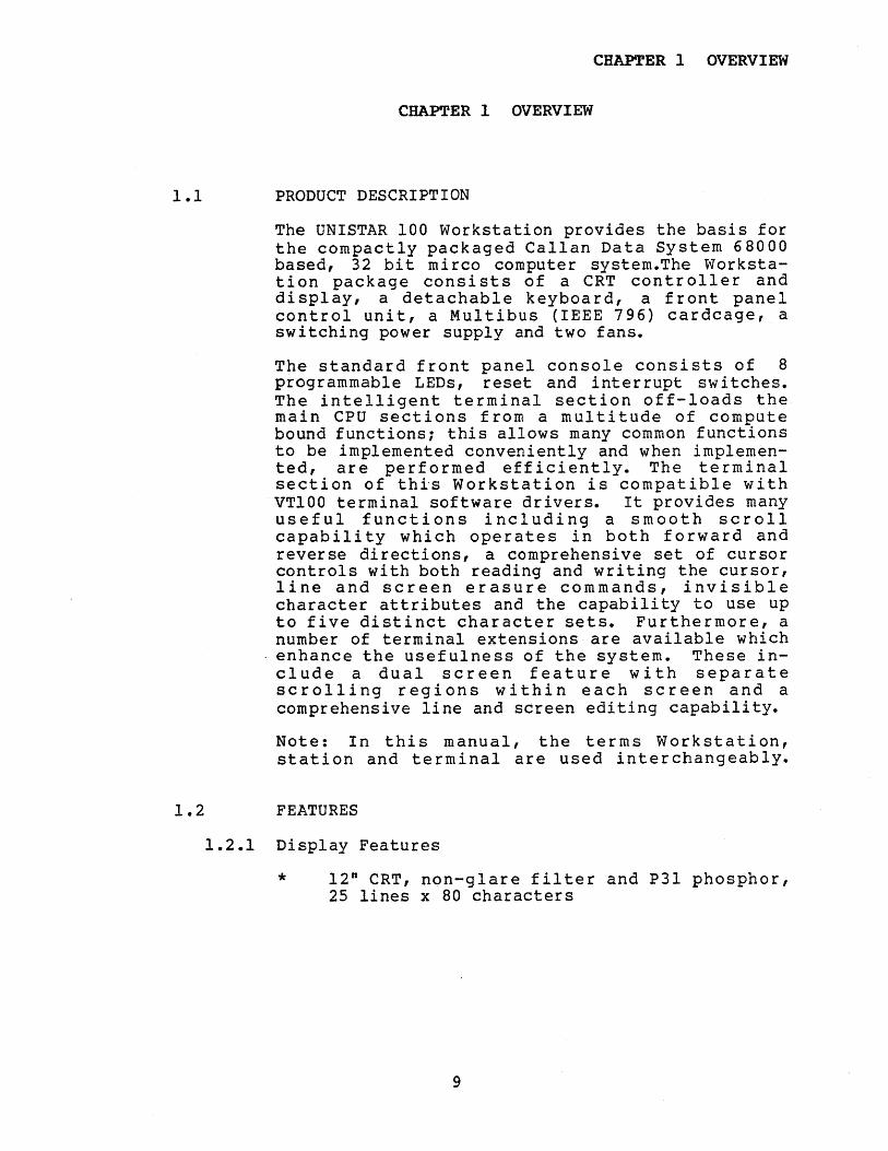
The UNISTAR 100 Workstation provides the basis forthe compactly packaged Callan Data System 68000based, 32 bit mirco computer system.The Workstation package consists of a CRT controller anddisplay, a detachable keyboard, a front panelcontrol unit, a Multibus (IEEE 796) cardcage, aswitching power supply and two fans.
The standard front panel console consists of 8programmable LEDs, reset and interrupt switches.The intelligent terminal section off-loads themain CPU sections from a multitude of computebound functions; this allows many common functionsto be implemented conveniently and when implemented, are performed eff iciently. The te rminalsection of this workstation is compatible withVT100 terminal software drivers. It provides manyuseful functions including a smooth scrollcapability which operates in both forward andreverse directions, a comprehensive set of cursorcontrols with both reading and writing the cursor,line and screen erasure commands, invisiblecharacter attributes and the capability to use upto five distinct character sets. Furthermore, anumber of terminal extensions are available whichenhance the usefulness of the system. These include a dual screen feature with separatescrolling regions within each screen and acomprehensive line and sCreen editing capability.
Note: In this manual, the terms Workstation,station and terminal are used interchangeably.
1.2 FEATURES
1.2.1 Display Features
* 12" CRT, non-glare filter and P3l phosphor,25 lines x 80 characters
9
CHAPTER 1 OVERVIEW
*
*
*
*
*
***
*
*
*
*
**
*
Clear characters on a 9 x 13 dot matrix with3 dot descenders
Split screen capability with separate scrollregions within each screen
A dual mode command processing capabilityfor processing either VT100 or VT52 commands;the mode is selectable either by a hardwareswitch, a software command or both
Smooth scrolling capability, in both forwardand reverse directions
Complete cursor control commands
Read and write cursor commands
Comprehensive tabulation commands
Comprehensive line and screen erasureCommands
Comprehensive line and screen editingcommands
Software control of LEDs on front panel andkeyboard
Software selection of 3 supplied charactersets one of which has forms characters whichare useful in the construction of forms andgraphs; two more character sets are userinstallable
Invisible character attributes, to increaseintensity, underline, blink, reverse videoand overstrike characters
95 displayable characters
Monitor mode to display all 33 controlcharacters
Local self diagnostic
10
CHAPTER 1 OVERVIEW
1.2.2 Indicators and keys
*
*
*
*
*
16 status lights on the keyboard and frontpanel; 8 are programmable
82 typewriter like keys including 4 cursorcontrol keys, 5 function keys and a 18 keyauxiliary keypad
3 computer controlled keyboard modes
Smooth scroll control key
Break key
1.2.3 Communications Interface
*
*
**
*
RS232 CPU Interface
15 separate Baud rates from 50 to 9600 Baud
7 or 8 data bits
Parity enable or parity ignore
Odd or even parity
1.2.4 Internal Controls
**
*
Video Adjustments
Reverse video intensity
Bold intensity adjustment
1.2.5 Switch Selectable Features
**
***
*
*
AUTOWRAP mode select
Auto XON/XOFF transmission select
LNM mode (Linefeed/Newline) select
Margin bell select
VT100/VT52 mode select
Blinking or steady cursor select
Block or dash cursor select
11
CHAPTER 1 OVERVIEW
* Normal or reverse video select
* On Line or Local/Test mode select
1.2.6 External Controls
***
Video intensity adjustment
Video contrast adjustment
Keyclick enable/disable select
1.3 CONTROLS
The following is a brief description of importantWorkstation controls and components:
1.3.1 Video Unit
The large screen area of the front of the unitdisplays 25 lines of 80 characters each.
1.3.2 Rear Access Cover
This large removable cover of the main unit allowseasy access to the system modules located in theenclosed cardcage and easy access to a number ofvideo adjustments without exposing the CRT, thevideo processor and the power supply. The Multibus Bus cards can be operated on extenders withthis cover removed. The cover is secured with thetwo large screws at the rear of the cover.
1.3.3 Keyclick Enable Switch
The Keyclick Enable Switch is a rotary twoposition switch located at the lower right side ofthe main housing. There are three switches in thisarea and the Keyclick Enable Switch is the centerone. This switch controls the automatic electronickeyclick feature when a key is depressed. Facingthe switch, rotate the switch clockwise toactivate this feature.
1.3.4 Video Intensity Control
The video Intensity Control switch is located justforward of the Keyclick Enable Switch. Rotate thecontrol clockwise to increase the brightness ofthe display.
12
CHAPTER 1 OVERVIEW
1.3.5 Video Contrast Control
The video Contrast Control is located just behindthe Keyclick Enable Switch. Rotate the controlclockwise to increase the contrast of the display.The recommended adjustment is to adjust theintensity to maximum; then adjust contrast to acomfortable setting. A low contrast settingresults in a not fully displayed cursor.
1.3.6 Front Panel LEDs
These 8 LED's are located on the front panel. Thelights are denoted, from left to right, D7 thruDO. These lights are controlled by the hostcomputer. D7, D6, and DS are reserved for futureuse as 68000 CPU board panel displays.
1.3.7 Keyboard Connecting Cable
This cable connects the Keyboard module to themain Workstation unit. This telephone stylecoiled cable provides easy disconnect at eitherthe keyboard or Workstation and allows flexiblekeyboard positioning for operator comfort.
1.3.8 Keyboard Module
The keyboard module consists of an LED display andtwo keyboard modules, a main and an auxiliarykeypad. The keyboard features sculptured keys andcontoured key rows arranged like an officetypewriter, permitting convenient operator use.The keyboard layout is identical to the DEC VTOOkeyboard layout.
1.3.9 The Main Keyboard
The main keypad is organized like a conventionaltypewriter and consists of the majority ofalphanumeric keys, the control keys, the spacebar, the sc~oll ~ontrol key, the PFO function key,the break key and the the cursor control keys.
1.3.10 The Auxiliary Keypad
The auxiliary keypad is an 18 key keypad locatedto the right of and on the main keypad. Thiskeypad is often used for high speed data input.The keyboard contains a comma, a minus, a period,an ENTER, four function and 10 numeric keys.
13

CHAP'l'ER 1 OVERVIEW
1.3.11 LED Keyboard Display
The keyboard LED display is located on thekeyboard over the numeric keys. The display isused to indicate a number of Workstation stateswhich are independent of the application programand to indicate programmable system states whichare dependent on the application program. The OnLine, Local, Keybd Locked and Scroll Disablelights represent independent terminal states; Llthrough L4 represent programmable dependent systemstates.
1.3.12 Video Adjustments
Some of the video adjustments are located on therear main bulkhead. After removing the rearaccess cover and f acing the rear of the uni t, thevideo adjustments are located on this bulkheadjust to the left and above the fan housing. Theseadjustments are set at the factory and normallyshould not be changed. However, the user mayeasily adjust these controls using a screwdriver.The top faint adjustment controls the faint(normal intensity) character intensity. Rotatethe control clockwise to increase intensity. Thebottom reverse adjustment controls the reversevideo intensity. Rotate clockwise to increasereverse video intensity. Refer to the CDlDOMaintenance Manual for a description of theremainder of video adjustments.
1.3.13 Switch Selectable Options
The switch Selectable Options are set by twovertical banks of DIP switches located below thevideo adjustments. Switch bank 1 is the top bankand switch bank 2 is just below this. Theseswitches determine a multitude of hardwareselectable options. For ini tial checkout andoperating the diagnostic described in section 1.4,all switches should be in the ON position (to theright when facing the switches). For themajority of software and setup procedures theusual choice is that all switches are placed inthe ON (right) position. The exact setting ofthese switches is critical for the correctoperation of the Workstation. Set these switchescautiously with respect to the ON and OFFpositions. A switch being in the ON position doesnot necessarily imply its designated function isenabled. Furthermore, some of these switchesdetermine terminal modes which later may be
14

CHAPTER 1 OVERVIEW
altered under host computer control. Refer tosection 2.6 for a complete description of theseswitches.
1.4 INITIAL CHECKOUT PROCEDURE
1. Connect keyboard to main unit via thekeyboard connecting cable.
2. Remove the two rear cover mounting screws andremove the cover. Verify or set voltageselector and line frequency to match theline power requirements.
The vol tage and frequency are both selectedby the voltage selector switch. The leftposition is 60HZ/115V and the right positionis 50HZ/230V.
Set the Local/On Line switch to local (OFF)to prepare for running the diagnostic. Besure all other switches are set to the right(ON) position.
3. Turn the power switch OFF, check to verifythat the line cord is properly installed andthe plug is connected to the appropriatepower source.
4. Turn on the power switch. The station willexecute the self-test diagnostic when poweris applied to the unit and the Local/On Lineswitch is set to Local.
The following sequence of events occurs ifthe unit is operating satisfactorily:
a. The local LED on the main keyboardwill illuminate, indicating thekeyboard unit is receiving power.
b. After a one second delay, the eightlights on the keyboard anddiagnostic lights on the frontpanel will illuminate. After onehalf second, all lights will be off(except On Line).
15
CHAPTER 1 OVERVIEW
c. Light 001 on front panel will beon, indicating end of Test 1, theCPU test.
d. After one second, light Dl will beon, indicating end of Test 2, thePROM integrity test.
e. After approximately 80 seconds,light D2 will be on, indicating theend of Test 3, the Memorydiagnostic.
f. After one second, light D3 will beon, indicating the end of Test 4and that the Memory to Memoryhardware logic is properlyfunctioning.
g. After one second, light 04 will beon, indicating the end of Test 5,indicating the internal clocks areproperly functioning.
h. Lastly, the unit will display thecharacter set.
7. Enable Keyclick by rotating the keyclickEnable switch clockwise.
8. Press the return key. A slight audible clickwill be heard and the cursor will move toposition 1, the furthermost left position ofthe second line.
9. Type 22 linefeeds; the top line will scrolloff the screen and what was the second linewill move to the top of the screen, and theoriginal bottom line will be blank.
10. Turn off the unit and re-configure for online operation. Reset Local/On Line DIPsw itch to On Line (ON).
16
CHAPTER 2 OPERATOR INFORMATION
CHAPTER 2 OPERATOR INFORMATION
2.1 GENERAL INFORMATION
The UNISTAR 100 Integrated Workstation is a videoterminal containing an integrated 68000microcomputer system, disks and based onMultibus/IEEE 796 system bus architecture. Datagenerated by the keyboard is asynchronouslytransmitted via an internal serial connection tothe 68000 microcomputer and circuit boards in thecardcage; data generated by these boards andtransmitted by the same connection either isdisplayed on the screen or implements a terminalcontrol operation (such as erase the screen orturn on an LED).
Also, inputs generated by the front panel aredirectly transmitted to the card cage motherboard,which may be utilized by the computer.
Detailed operation of the terminal is modified byhardware switch settings described in this chapterand by the software commands described in Chapter3, PROGRAMMERS INFORMATION.
This chapter describes, from the operator'sviewpoint, the operation of the various sectionsof the workstation. The last part of the chapterdescribes the power up/self diagnostic sequence.
2.2 THE VIDEO SECTION
2.2.1 Displayed Characters
Characters received from the RS232 interface aredisplayed on the screen. Normally the 95characters of the primary ASCII character set (20Hex through 7E Hex) are displayed and the 33control characters (00 Hex through IF Hex and 7FHex) are not di splayed. The controls ei therperform specified functions or are ignored.However, if the terminal is in the softwaresettable monitor Mode, the special graphicsassociated with these codes are displayed and theusual control action is ignored.
The host computer under software control mayselect 3 character sets which are resident in theprimary ROM supplied with the Workstation. Thesesets are the US ASCII, the UK and the Special
17
CHAPTER 2 OPERATOR INFORMATION
·Graphics set. Furthermore, if the alternatecharacter ROM has been installed by the user, thehost computer may specify two additional charactersets. These sets are the called the Alternatecharacter set and the Alternate Special Graphicscharacter set. The actual character font or thespecial graphics in the alternate ROM, arecompletely user defined.
2.2.2 Partitions
The terminal's video controller displays 25 linesof 80 characters each. The terminal supports asplit-screen capability. whereby these 25 lines areconsidered to be divided into two groups calledpartitions. One partition may contain p completelines (where p must be greater than or equal tozero but less than or equal to 25); therefore, theother partition contains 25-p lines. A partitionis defined and selected by software command. Onpower up, the screen is separated so that the toppartition contains the customary 24 lines and thebottom partition contains 1 line.
2.2.3 Scroll Area
Under software control, the parti tion itself maybe divided into two regions: a scroll regionnested within the partition, and a fixed lineregion, part of which is above and part of whichis below the scroll region.
Display or control operations mayor may not berestricted to the scroll region. However, thescroll process is always restricted within thisregion.
2.2.4 Attributes
Under software control, the terminal assigns anumber of attributes or renditions to displayablecharacters. Examples of these attributes are bold(increased intensity), blinking and underlinedcharacters. Also, attributes may be combined toform compound attributes such as blinkingunderlined characters.
18

CHAPTER 2 OPERATOR INFORMATION
2.2.5 Modes
The behavior of the terminal is affected by anumber of modes. Some of these modes areinitialized by the rear panel switch settingsdescribed in this chapter, and others are set bysoftware commands from the host to the terminal.Others are affected by both the switch setting andsoftware commands. Any mode which may be set byei ther a swi tch setting or by a software commandis first initialized according to the switchsetting on power up, a terminal reset command orany change whatsoever in any switch settings.After the mode is set, it may be changed by asoftware command from the host. Thus, a modeindicated by a rear panel setting does notnecessarily reflect the current terminal mode.Modes which are affected only by the rear panelswitches are Auto XON/XOFF and Margin bell. Modeswhich are affected by software commands only areInse rt/Repl ace, Verti cal Edi ti ng, Cur sor Key,Origin, Monitor and Special Erasure. Modes whichare affected by both the rear panel switches andsoftware commands are Linefeed/New Line, ANSI/VT52and Autowrap.
2.3 FRONT PANEL LED
The Front Panel LED section consists of the Runlight and LED's D7 through DO. LED's D7, D6, andD5 are reserved for future use by Callan DataSystems as 68000 CPU board status indicator. Theremaining LED's D4-DO are used by the terminalcontroller during LOCAL mode self test and areavailable in ON-LINE as programmable displaysthrough the terminal controller.
2.4 THE KEYBOARD MODULE
2.4.1 Keypad LED Display
Eight LED's are on the keyboard. Four, Ll throughL4 are so f twa r e con t roll a b 1'e , wher e a s theremaining four represent states of the terminal.These four LED's are described in the followingsections.
19
CHAPTER 2 OPERATOR INFORMATION
Online LED
The On Line light indicates that the station isset by the rear panel Local/On Line switch to theOn Line position. In this mode, the usual mode,characters and controls typed on the keyboard aretransmitted to the host computer via the RS232connection. When this light is on, the Locallight is off.
Local LED
The Local light indicates that the station is inthe Local/test mode as set by the rear panelLocal/On Line switch. In this mode, charactersand controls generated at the keyboard are "loopedback" and are received as an input from the RS232interface. This mode is useful for diagnosticpurposes. In fact when in this mode, and power isfirst turned on or a terminal reset is executed,the terminal initiates the self-test diagnostic.When this light is on, the On Line light is off.
Keybd Locked LED
The Keyboard Locked LED, usually indicates thatthe host computer has deactivated the keyboard.The host computer locks the keyboard bytransmitting the XOFF control character to theterminal. Until the keyboard is unlocked by atransmission of an XON, struck keys will beignored. Another reason why this light is on isif the terminal is in the Local mode and the rearpanel Auto XON/XOFF is enabled (switch 1-7 ON) andthe operator strikes control S to stop scrolling,the terminal will send an XOFF character. Butthis character is echoed by the terminalcontroller which in turns locks the keyboard. Inthis case, type control 0 to unlock the keyboard.
Scroll Disabled LED
The Scroll Disabled light indicates that theterminal is not processing input characters andcontrols and therefore, scrolling cannot occur.This condition occurs when the XON/XOFF feature isenabled (switch 1-7 ON) and control S has beenentered at the keyboard to suspend scrolling. Toexit this condition to permit scrolling, the usermust type control 0, whereby the light will gooff.
20
CHAPTER 2 OPERATOR INFORMATION
Lights Ll through L4
These lights are controlled by software commandsfrom the host computer.
2.4.2 Main and Auxiliary Keypads
The main keypad contains control and alphanumerickeys which are arranged like a standard officetypewriter. The keypad also contains one of the 5function keys, 4 cursor control keys and the breakkey. The auxiliary keypad contains the 4 otherfunction keys, the numbers and the characters andcontrols often used for high speed operator input.
The keys, when struck individually or incombination with the shift and control keys,produce codes which are transmitted to the hostcomputer. All 128 ASCII codes may be generated.(Refer to Appendices B, C and D for the codesequences produced).
Under software control, the keyboard may be placedinto a number of alternate modes. If the terminalis in the ANSI/VT100 mode, under software control,the keyboard may be placed into either of twomodes, the Numeric or the Keypad Application mode.The default or power up mode is called the Numericmode. In this mode, on the auxiliary keypad the10 numerals, the minus, the period, the comma, andthe ENTER keys send the same ASCII codes as thecorresponding keys on the main keypad. In thealternate keypad mode (the Keypad Applicationmode) the 10 numerals, the minus, the period,thecomma and the ENTER keys send different sequencesthan in the Numeric mode.
Also, while the unit is in the ANSI/VT100 mode,the 4 cursor control keys are affected by thestate of Cursor Key mode. The default or power upstate is called Cursor Key mode reset. When inthis state, the cursor control keys generate the90de sequences which, if echoed by the hostcomputer, will implement the indicated cursorcontrol functions. If Cursor Key mode is set (bysoftware command), the four cursor control keystransmit different code sequences which whenechoed do not result in the indicated cursormovements.
If the terminal is in the VT52 mode, the keyboardmay also be placed in either the Numeric or theApplication modes and the comments decribing thedifferences between modes is as described above,although the actual code sequences generated are
21
CHAPTER 2 OPERATOR INFORMATION
di ff er ent (ref er to Appendix C). But in the VTS 2mode, the cursor keys do not have an alternatemode.
The advantage of the keyboard having alternatemodes is that in many applications it is usefulfor the application, program to differentiatebetween the same captioned keys on the mainauxiliary keypads. Refer to Appendices B, C and Dfor a description of the code sequences generatedby the various keypad modes.
The keyboard has an auto repeat feature. Thisallows a key to be automatically repeated at therate of approximately 20 characters per secondwhen the key is held down for more than one half asecond. The auto repeat feature affects all keysexcept the following: PFO, ESC, SLOW SCROLL, TAB,RETURN and CNTRL (w i th any othe r key). The ENTERkey on the auxiliary keyboard has the auto repeatattribute.
Standard Alphanumeric Keys
On the main keypad, the non-control keys generatecodes dependent on the combination, if any, of theCAPS LOCK, SHIFT, and CNTRL keys, which may bedepressed simultaneously. However, the auxiliarykeypad, the PFO, the four cursor control keys, theBREAK key and the Scroll control key are notaffected by these three control keys.
BREAK KEY
Typing the BREAK key causes the transmission lineto forced to its zero state for 0.2333 secondsplus or minus 10 percent.
BACKSPACE
Depression of this key will transmit the ASCIIcode for the backspace (08H) to the host computer.
CAPS LOCK
The CAPS LOCK Key is a toggle action key. Whenthe CAPS LOCK function is enabled, the LED on thekey is illuminated and the terminal transmitsupper case alphabetic characters regardless of thestate of the SHIFT key. To disable this function,press the key again, whereby the LED will go offand the terminal will transmit the codes asadjusted by the SHIFT key.
22
CHAPTER 2 OPERATOR INFORMATION
CURSOR CONTROL KEYS
The four cursor control keys are used to controlthe position of the cursor. In the ANSI/VT100mode with the Cursor Key mode reset or in the VT52mode, these keys transmit the correct codesequence which if echoed by the host, will enablethe terminal to perform the indicated cursormovements.
The up arrow key moves the cursor up one row,unless the cursor is .already at the top of thescrolling region or at the top of the currentlyselected partition. The down arrow moves thecursor down one row, unless the cursor is alreadyat the bottom of the scrolling region or at thebottom of the selected partition. The left arrowmoves the cu r sor left one character posi tionunless at the left margin. And the right arrowmove the cursor right one character positionunless at the right margin.
If the terminal is in the ANSI/VT100 mode and theCursor Key mode is set, the code sequencesgenerated by the cursor keys will be ignored bythe terminal if echoed by the host computer.
CNTRL
This key is used in conjunction with analphanumeric key to generate an ASCII controlcode. (Refer to Appendix B for the specific codesgenerated. )
DELETE
Depression of this key transmits the deletecharacter code (7FH) to the host computer.
ENTER
In either the ANSI or VT52 modes and in Numericmode, the ENTER key produces the identical codesas return key on the main keypad. These keysgenerate the ASCII carriage return code (ODH). Inthe Keypad Application mode, the ENTER keygenerates a specific code sequence for ANSI orVT52 modes. The code sequences generated arelisted in Appendix C and D.
23
CHAPTER 2 OPERATOR INFORMATION
ESC
This key trnsmlts the ASCII escape character code(lBH) ,
FUNCTION KEYS (PFO through PF4)
The five function keys, PFO on the main keypad andPFI through PF4 on the auxiliary keypad, transmitspecial code sequences, which are described inAppendices Band C. The sequences generated arenot affected by the VT100 or VT52 mode choice orby Numeric or Keypad Application mode choice.Also, if the terminal is in the ANSI mode, onlythe last character of the code sequence generatedby these keys will be displayed at the terminal ifthe host computer echoes the sequences. No otheraction occurs, however. If the terminal is in theVT52 mode, the code sequences generated by thesekeys are completely ignored if echoed by the hostcomputer.
LINEFEED
This key transmits the ASCII linefeed code (OAH).
RETURN
This key transmits the ASCII carriage returncode (ODH).
SHIFT
The shift key is used in conjunction with otherkeys to generate specific codes. Usually theshift used with an alphabetic key produces codesfor upper case characters. (Refer to Appendix Bfor the specific codes generated.)
SLOW SCROLL
This key does not transmit a code to the hostcomputer but rather controls the smooth scrollfeature. Smooth scroll is enabled and disabled bysuccessive depressions of this key.
Scrolling is the process whereby all lines of thescrolling regi~n are either shifted up or down onerow, depending upon the direction of the scroll,to make room for a new line of incoming data.For forward scroll, the scroll region is shiftedup, the original top line is lost and the bottomline is erased. The new incoming data isdisplayed at the bottom of the scroll region. Forreverse scroll, the scroll region is shifted down,
24

CH~ER 2 OPERATOR INFORMATION
the original bottom line is lost and the top lineis erased. The new incoming data -is displayed atthe top of the scrolling region. When the smooth-scroll feature is disabled, the scrolling processappears to occur instantly and discontinuously.When the feature is enabled the scrolling processoccurs relatively slowly and continuously.
As long as sufficient data is available, thesmooth scroll rate is maintained at 4.6 and 3.9lines per second at 60 and 50 HZ operation,respectively. The effect is as if the data is ona continuously and steadily moving scroll behindthe partition.
Control of the incoming data rate, which could begreater than the smooth scroll rate, isaccomplished by two mechanisms. The first,activated by the rear panel XON/XOFF switch, isthe process of having the terminal automaticallytransfer an XOFF (DC3) when the terminal'S inputbuffer is fairly full. The host's software mustbe designed to stop transmitting until theterminal automatically sends an XON (DCI), whichis done when the input buffer is almost empty.The second mechanism, independent of the XON/XOFFswitch, is when the buffer is very full, RequestTo Send (RTS) of the RS232 terminal isdeactivated. Then when the buffer is fairlyempty, Request To Send is reactivated. Thus, thehost computer's RS232 interface, in the many caseswhich use these signals, automatically limits itsown transmission rate.
If the terminal is in the smooth scroll mode andthe operator types either XOFF (Control S) or XON(Control Q), the terminal does not necessarilytransmit these codes. Under these circumstances,XOFF and XON are used by the terminal to suspendand resume, respectively the scrolling process.Of course, if XOFF is used to suspend thescrolling process, the terminal subsequentlytransmits an XOFF when the input buffer has beensufficiently filled. Likewise, an XONsubsequently is sent to the host when theterminal's input buffer is sufficiently empty.
Occasionally, the terminal will be taken out ofslow scroll mode wi thout a depression of thesmooth scroll key. This will occur if the hostcomputer selects the alternate partition which maycontain a scrolling region with less than 2 lines,the minimum necessary for smooth scrolling. Whenthis happens, the terminal is automaticallyremoved from the smooth scroll mode. Now if the
25
CHAPTER 2 OPERATOR INFORMATION
host computer reselects the original partition, itwill remain in the non smooth scroll mode.
One last use of the smooth scroll key is to removethe t e r min a I fro m M0 n.i tor mode. If the h0 s tcomputer places the terminal into Monitor mode,then the only way for the terminal to be removedfrom this mode is by the operator depressing thesmooth scroll control key.
TAB KEY
The TAB key transmi ts the ASCII code for Tab. Ifthe host computer echoes this code, the cursoradvances to the next set tab position. If no tabsare set to the right of the current activeposition, the cursor advances to the lastcharacter position. Tabs are set and reset undercomputer control. On power up or reset, tabs areset at every eighth character position beginningwith the ninth character position.
2.5 THUMB WHEEL ADJUSTMENTS
Three user adjustments are located on the rightunderside of the unit:
2.5.1 Video Intensity
This adjustment sets the overall screen intensity.It is operated in conjunction with the videocontrast adjustment described in section2.7.First, adjust video intensity to its maximum.Then adjust the contrast until the charactersappear clear. Then readjust the video intensityto a comfortable operational level. Contrast canthen also be fine-tuned as required.
Rotate the thumbwheel clockwise to increasedisplay intensi ty and rotate counterclockwise todecrease intensi ty.
2.5.2 Keyclick Enable
Keyclick provides an acoustic feedback when a key,other than control, is depressed. Rotate theswitch clockwise to enable keyclick; rotatecounterclockwise to disable keyclick.
26

CHAPTER 2 OPERATOR INFORMATION
2.5.3 Video Contrast
This control is used to adjust the background andcharacter intensity. This control is used inconjunction with Video Intensity described in2.7.
Rotate clockwise to increase contrast, rotatecounterclockwise to decrease contrast.
2.6 REAR PANEL DIP SWITCH SETTINGS
Access to the two banks of eight switches isgained by removing the outer case. These switchesmodify the terminal's behavior. When facing therear of the unit, the ON position is to the rightand the OFF is to the left. Note that if a switchis in the ON position it does not necessarilyimply that the associated function is enabled.The following page describes the various switchoptions.
27

CHAPTER 2 OPERATOR INFORMATION
SKI - UPPER SWITCH BANK
SWITCH SWITCH OFF POSITIONNUMBER }lAME (LEFT)
1-8 Autowrap AutowrapEnabledEnabled
1-7 XON/XOFF Disabled1-6 New line mode Enabled1-5 Margin Bell Enabled1-4 ANSI/VT52 mode VT52 mode1-3 Cursor Blink Steady Cursor1-2 Cursor type Dash Cursor1-1 Screen mode Reverse Video
ON POSITION(RIGHT)
AutowrapDisabledDisabledEnabaledDisabledDisabledANSI modeBlinking CursorBlock CursorNormal Video
SN2 - LOWER SWITCH BANK
II
n
Online8 data bitsOdd parityIgnore parity
Local/Test mode7 data bitsEven parityProcess parity
select code
Local/OnlineData lengthParityparityBaud raten
2-82-72-62-52-42-32-22-1
BAUD RATE SELECT CODE4 3 2 1 SW2
(N=ONi F=OFF)
N N N NN N N FN N N FN N F FN F N NN F N FN F F NN F F FF N N NF N N FF N F NF N F FF F N NF F N FF F F N
9600 BAUD7200480036002400200018001200
600300150134.5110
7550
(2 stop bits)(2 stop bits)(2 stop bits)
Figure 2-1Rear Panel DIP Switch Settings
28
CHAPTER 2 OPERATOR INFORMATION
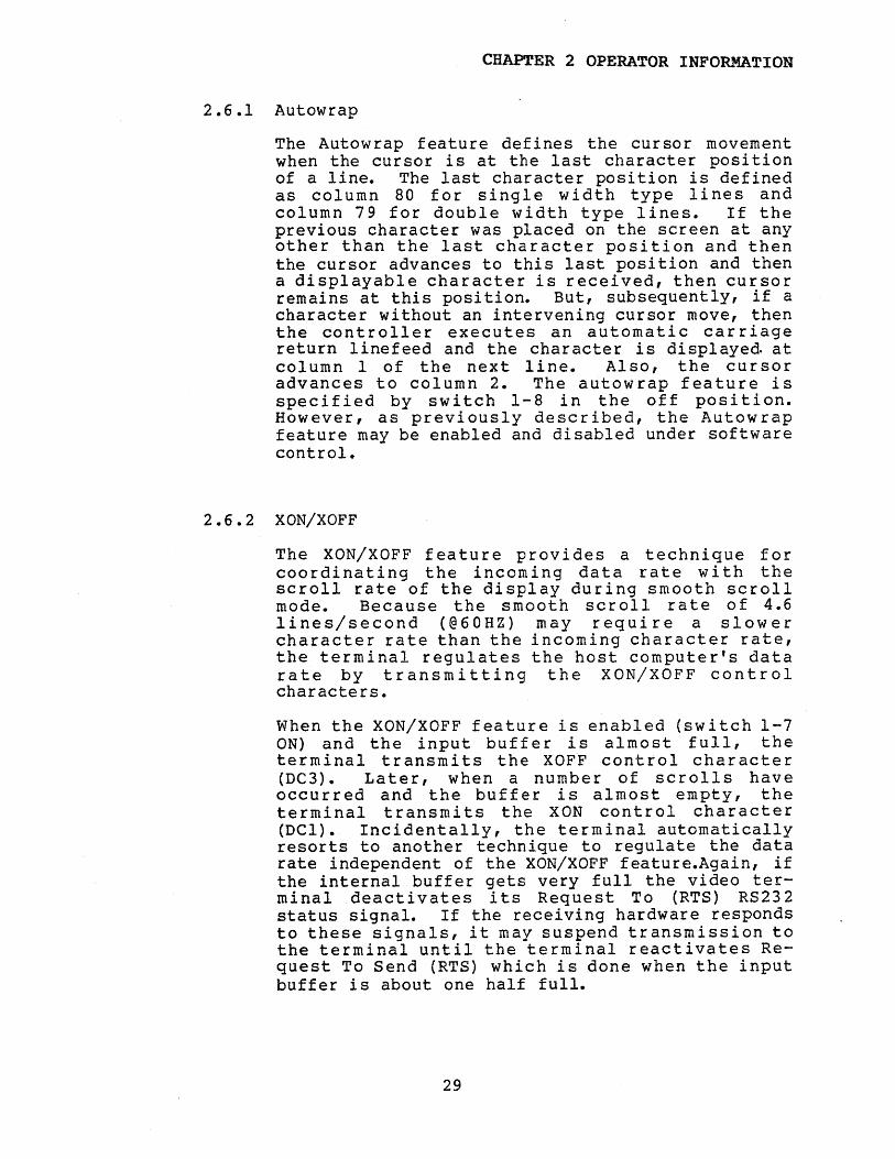
2.6.1 Autowrap
The Autowrap feature defines the cursor movementwhen the cursor is at the last character positionof a line. The last character position is definedas column 80 for single width type lines andcolumn 79 for double width type lines. If theprevious character was placed on the screen at anyother than the last character position and thenthe cursor advances to this last position and thena displayable character is received, then cursorremains at this position. But, subsequently, if acharacter without an intervening cursor move, thenthe controller executes an automatic carriagereturn linefeed and the character is displayed atcolumn 1 of the next line. Also, the cursoradvances to column 2. The autowrap feature isspecified by switch 1-8 in the off position.However, as previously described, the Autowrapfeature may be enabled and disabled under softwarecontrol.
2.6.2 XON/XOFF
The XON/XOFF feature provides a technique forcoor d i nat i ng the inc 0 min g d a t a rate wit h thescroll rate of the display during smooth scrollmode. Because the smooth scroll rate of 4.6lines/second (@60HZ) may require a slowercharacter rate than the incoming character rate,the terminal regulates the host computer's datarate by transmitting the XON/XOFF controlcharacters.
When the XON/XOFF feature is enabled (switch 1-7ON) and the input buffer is almost full, theterminal transmits the XOFF control character(DC3). Later, when a number of scrolls haveoccurred and the buffer is almost empty, theterminal transmi ts the XON control character(DCl). Incidentally, the terminal automaticallyresorts to another technique to regulate the datarate independent of the XON/XOFF feature.Again, ifthe internal buffer gets very full the video terminal deactivates its Request To (RTS) RS232status signal. If the receiving hardware respondsto these signals, it may suspend transmission tothe terminal until the terminal reactivates Request To Send (RTS) which is done when the inputbuffer is about one half full.
29
CHAPTER 2 OPERATOR INFORMATION
2.6.3 New Line Mode
If New Line Mode is enabled (switch 1-6 ON), thenthe terminal controller follows the carriagereturn character with a line feed on transmissionand follows the linefeed character with a carriagereturn on reception. If New Line Mode is notenabled, the carriage return or the linefeed arenot followed by any character in either case. NewLine Mode is initialized according the rear panelDip switch every time the controller in powered-upor anytime any rear panel switch is changed. NewLine Mode may be set or reset under host computercommand thus altering the mode indicated by therear panel switch.
2.6.4 Margin Bell
The Margin Bell feature sounds an alarm wheneverthe cursor is moved to character position 72 onthe screen and a character is received to bedisplayed at that position. Margin Bell isdisabled if switch 1-5 is ON and is enabled ifOFF.
2.6.5 VT52/VTIOO Mode
The terminal controller functions in either of twomajor modes: VT52 mode or ANSI/VT100 mode.
The OFF position (switch 1-4 OFF) corresponds tothe VT52 mode. In .this mode the terminal willrespond to 18 commands from the host computer; allof which, except one, are designated by simple twocharacter escape sequences. The exception is thedirect cursor positioning command requires a fourcharacter sequence. The Auxiliary keypad canexists in two modes, the keypad numeric mode orthe keypad application mode. Also, this modeincludes contains a number of editing commandssuch as delete line and insert line.
The ON position corresponds to the ANSI/VT100mode. In this mode an extensive array of commandsare available to control the terminal. Also, thekeyboard may function in a variety of modes. Theauxiliary keypad may exist in two modes asdescribed above. Additionally, the cursor keysfunction in either of two modes. Communicationwith the terminal is in multi-character Asciicharacter sequences according to the protocoloutlined in the ANSI standard X3.64. The hostcomputer may change the initial mode setting sothat the mode indicated by the rear panel switch
30
CHAPTER 2 OPERATOR INFORMATION
does not necessarily reflect the actual currentterminal mode.
2.6.6 Cursor type
The cursor type is controlled by switch 2-3. Inthe ON position, the controller uses a blinkingcursor; in the OFF position the cursor does notblink.
2.6.7 Cursor Shape
If this switch (1-2) is in the ON position, theterminal generates a reverse video block cursor;if the switch is in the OFF position, the terminalgenerates a dash cursor.
2.6.8 Reverse Video
If this switch (1-1) is in the ON position,character representation is light characters on adark block matrix; if the switch is in the OFFposition, character representation is darkcharacters on a light block background.
2.6.9 Local/Online
This switch (2-8) determines if the keyboardcommunicates with the external host computer orinternally with the terminal itself. In theOnline mode (switch 2-8 ON), data generated by thekeyboard action is transmitted through the RS232connection to the host computer. The transmissionitself will in no way change the status or displayof the workstation. Only when a receiving CPUprocesses the data and transmits the data back tothe station is the state of the station altered.If the switch is in the Local/Test mode (switch 28 OFF), the characters generated by the keyboardare processed as if they were received directlyfrom a host computer.
Also, if the switch is in the Local mode whenpower is turned on, the terminal initiates theself-test program. Refer to section 1.4 for adescription of the diagnostic.
31

CHAPTER 2 OPERATOR INFORMATION
2.6.10 Data Length
If this switch (2-7) is in the ON position, theterminal transmits 8 data bits and expects toreceive 8 data bits over the communication line.If the s witch i s in the OFF po sit ion, thecommunication uses 7 data bits. The data bits areexclusive of the start, stop or parity bits.
2.6.11 Parity
If parity is enabled (described in the nextsection), and the Parity switch (2-6) is ON, oddparity is generated for transmission over theRS232 communication line and odd parity isverified on received data. If the switch is OFF,even parity is generated and verified.
2.6.12 Parity Enable
If this switch (2-5) is in the ON position, parityis neither generated on transmission nor checkedon reception over the communication line. If theswitch is in the OFF position, parity is generatedon transmission and is checked on reception. Thesense of the parity is according to that outlinedin the previous section.
When a parity, end of frame or data overrun erroris detected during reception, the ASCII graphicfor a delete, the checkerboard, is displayed.
2.6.13 Baud Rate Select
The Baud rate is determined by switches 4 thru 1on the lower switch bank. Refer to Figure 2.1 forthe switch settings. If the selected baud rate isstrictly greater than 110 Baud, then 1 stop bit isgenerated by the terminal for transmission, andthe hardware checks for 1 stop bit on reception.If the Baud rate is less than or equal to 110Baud, then 2 stop bits are generated and checked.
2.7 REAR VIDEO ADJUSTMENTS
Two attribute intensity adjustments are located onthe rear panel for Faint and Reverse Videocharacter fields. Both are set at the factory andshould not normally require readjustment.
32

CHAPTER 2 OPERATOR INFORMATION
2.7.1 Faint
The normal intensi ty characters are called faintand are at a lower intensity than bold(highlighted) characters. The choice of characterintensity is selected by the host computer undersoftware control. The Faint (normal intensity)adjustment is rotated clockwise to increase theintensity of normal intensity characters.
2.7.2 Reverse Video
This adjustment is rotated clockwise to increasethe intensity of reverse video characters.
2.8 INSTALLATION OF ALTERNATE ROM
Two additional character sets can be implementedvia the installation of a custom programmed 2716EPROM. These alternate character sets areselectable under computer command. Refer to theUNISTAR System Manual for the appropriate installation procedures.
2.9 POWER UP AND DIAGNOSTIC SEQUENCE
When power is first applied to the unit, anapproximate 2 second delay occurs after which oneof two sequences occur: If the rear panelLocal/On Line switch is in the Online position,the alarm is sounded, the screen is erased, thecursor is placed in the home position and theterminal is ready to communicate via the RS232line.
If the switch is in the Local/Test position, thediagnostic is initiated. This diagnostic isbriefly described in Chapter 1. If the testpattern is not displayed on the screen, then thefront panel light indicates the last successfultest.
33

CHAPTER 2 OPERATOR INFORMATION
34
CHAPTER 3 PROGRAMMERS INFORMATION
CHAPTER 3 PROGRAMMERS INFORMATION
3.1 GENERAL INFORMATION
This chapter concentrates on those aspects of theworkstation that are controlled by the hostcomputer. Communication with the terminal and LEDdisplay sections of the workstation is done via anRS232 connection using asynchronous 7 bit codesequences.
Using intelligence in the terminal section thehost computer can display, organize and manipulatecharacters on the screen; control and read thecursor; control the LED'S on the keyboard or onthe front panel~ and, can modify the codesequences generated by the keyboard.
The programmer should be aware that a computerinstalled in the card cage may receive varioushardware signals from the front panel.
3.1.1 VT100/VT52 Mode Operation
The terminal controller functions in either of twomajor modes: VT52 or VT100 mode. The mode isreinitia1ized according to the rear panel DIPswitch on power up or at any time this switch ischanged~ The OFF position corresponds to the VT52mode and the ON position corresponds to the VT100mode. At any time after the mode is set by aswitch setting, the mode may be changed undercommand control by the host processor.
In the VT52 mode, the terminal responds to alimited instruction set. All instructions exceptone are specified by simple two character escapesequences. The VT52 direct cursor positioningcommand is the exception. The majority of theterminal's capabili ties are evoked when thete rmi na1 is in the VT100 mode. In thi s mode, theterminal responds to an extensive array ofcommands. The communication protocol usedcorresponds to the ANSI X3.64 standard.
Later, the software mechanisms for switching toand from the VT52 and VT100 modes are described.Thus, even though many capabilities of theterminal are only available in the VT100 mode,they are readily available in the VT52 mode bytemporarily switching the terminal under software
35
CHAPTER 3 PROGRAMMERS INFORMATION
control into the VT100 mode, setting theappropriate state or executing the appropriatecommand, and then switching back to the VT52 mode.In this manual, the modes VT100 and ANSI are usedinterchangeably.
3.1.2 Partitions
Physically the screen displays 25 lines of 80characters each. From the software point of view,however, the screen is divided into two logicalscreens called partitions. The top partition,partition 0, may contain p lines and the bottompartition, partition 1, contains 25-p lines.
A partition may contain 0 lines; but if smoothscroll is to occur in the partition it mustcontain at least 2 lines. When the terminal isinitialized either on power up or execution of theRIS command, the screen is partitioned withpartition 0 having 24 lines and partition 1 having1 line. This organization is convenient for theoperation of most existing software. Thepartition may be changed by the PSR command and aspecific partition is selected by the SSPRcommand.
3.1.3 Scroll Area
Each partition may further be divided into ascroll region embedded within the partition and afixed line area having some of its lines above andsome below the scroll region. The scroll area isdefined by the SSCRL, Set Scroll Area, command.
Usually, the transfer of characters and thecursor control commands are restricted to withinthe selected scroll region. For instance, if thecursor is at the last line of the scrolling regionand a linefeed character is received, the lineswithin the region scroll up one line. Also, ifthe cursor is at the top line of the scrollingregion and the reverse line feed command isreceived, then the lines within the region scrolldown one line. As far as the cursor movementcommands are concerned, when the cursor is withinthe scroll region, a cursor up or a cursor downcommand never moves the cursor past the scrollboundaries. But certain commands are dependent onthe state of ORIGIN mode. For instance, if ORIGINmqde is reset, the absolute cursor positioncommand, CUP, or the cursor position report, CPR,is with respect to the partition origin and not
36
CHAPTER 3 PROGRAMMERS INFORMATION
the scroll region origin. If ORIGIN mode is set,then these commands use coordinates with respectto the scroll region origin.
3.1.4 Character Processing
Display character processing consists of thereceived character being entered at the currentcursor location, called the active position. Thecursor then advances one character position to theright on the current line, called the activeline. A character position requires one physicalscreen position for normal width lines and twophysical screen positions for double width lines.Refer the to section on double height/width linesin this chapter for a discussion of this point.The cursor movement, when at the last characterposition, depends on the rear panel switchsettings and a number of software setable modesdescribed in this chapter.
3.1.5 Alternate Character ROM
An alternate character set is available providingthe alternate ROM is installed. The activecharacter set is determined by two mechanisms.First the host software should choose either theGO or the Gl character set class. The GO classis initialized at power up or is reselected by thehost transmitting the SI control character. TheGl class is selected at any time by the hosttransmitting the SO control character. Fivecharacter sets are available in either the GO orGl class:
1. The DSASCII set which is defined by thestandard character ROM supplied at thefactory; this set is listed in AppendixA.
2. The United Kingdom set; this set isidentical to the DSASCII set describedabove but replaces the American poundsign with the English pound sign.
3. The Special Graphics set which defines anumber of special graphics and formcharacters; also, this character set isdefined in the supplied character ROM.
4. The Alternate Character ROM Standardcharacter set~ this character set isdefined in the user supplied alternateROM.
5. The Al ternate Character ROM SpecialGraphics set; this character set issupplied by the user in the alternatecharacter ROM.
37

CHAPTER 3 PROGRAMMERS INFORMATION
The specific set which is active in each class isdefined by the SCS, Select Character Set, command.The ASCII set in the GO class is defined as activeat power up or upon execution of the RIS command.
Each of the five character sets in the GO group isidentical to its counterpart in the Gl group.
3.1.6 Graphic Form Characters
As described in the above section, a number ofgraphic form characters are available as part ofthe Special Graphics character set. Thesecharacters are useful in the construction of formsand charts. Refer to Appendix A for a descriptionof these character s •
3.1.7 Attributes
Using the SGR command, characters may be assigneda number of attributes: characters may blink, bedisplayed at increased intensity, be displayed inreverse video, can be underlined and beoverstruck. Or, any combination of theseattrributes may be used simultaneously. Once arendition is defined, all characters transferredto the partition have this rendition until changedby the SGR command. Thus, the attributesassociated with a character are defined when theyare transferred to the screen and not, as in somesystems, where they; are placed. Prime renditionmeans non-blinking, normal intensity, normalvideo, not underlined and not overstruckcharacters. Reverse video means dark characterson a light block matrix unless the reverse videorear panel switch is in the reverse position(whereby reverse video means light characters on adark block matr ix).
3.1.8 Terminal Control
Terminal control is executed by using the 32control character s of the CO set, the deletecharacter or by the escape sequences, all of whichare discussed in this chapter.
3.1.9 Slow Scroll Considerations
Activation of the slow scroll capability isexercised by use of the slow scroll key. on thelower left portion of the keyboard or by the hostcomputer executing a mode reset or set commandwith the SLWSCRL parameter as described in Chapter2. However, if the host computer's RS232
38
CHAPTER 3 PROGRAMMERS INFORMATION
connection does not respond to the hardware'sRequest To Send (RTS) signal then the host'ssoftware explicitly must be designed so as toaccommodate the smooth scroll feature.
Specifically, the host's RS232 driver must bedesigned to recognize the XON (DCl) and XOFF (DC3)control characters. When the host receives XOFFit should transmit no more than 8 characters untilit receives an XON.
3.1.10 Modes
The behavior of the terminal is affected by anumber of modes. Some of these modes areinitialized by the rear panel DIP switch settingswhenever a power up situation is encountered, theRIS terminal command is executed or any DIP switchis changed. Other modes are set by softwarecommands from the host to the terminal. Andothers are affected by both the switch setting andsoftware commands. Any mode which may be set byeither a switch setting or by a software commandi s fir s tin i t i ali zed , as des c rib e d above,according to the switch setting on power up, a RISterminal command or any change whatsoever in anyrear panel switch settings. After the mode isset, it may be changed by a software command fromthe host. Thus, a mode indicated by a rear panelsetting does not necessarily reflect the actualcurrent terminal mode. Modes which are affectedonly by the rear panel switches are AUTO XON/XOFFand MARGIN BELL. These modes are described inChapter 2. Modes which are affected either bysoftware command and the rear panel switches oronly by software command are briefly describedhere and more fully described later in thechapter.
Modes which are affected by both the rear panelDIP switch settings and software control are LNMmode (Linefeed/New Line) which determines theaction of the keyboard on the operator striking acarriage return character or the action of theterminal upon receipt of a linefeed character;ANSI mode which determines if the terminalinterprets commands according to VT100 or VT52format; and AUTOWRAP mode which determines theaction of the cursor when at the last characterposition of the line.
The SLWSCRL mode is toggled by the SLOW SCROLLkeyboard key·or is affected by software command.
Modes which are affected by software command are
39
CHAPTER 3 PROGRAMMERS INFORMATION
IRM (Insert/Replace) which specifys whether areceived character is inserted at or replaces thecharacter at the cur rent cur so r posi tion; VEM(Vertical Edi ting Mode) which determines theaction of the terminal upon receiving the Insertor Delete line commands; CURKY (Cursor Key) whichdetermines the particular command sequence thatthe cursor keys send to the host when a keyboardcursor key is struck; ORIGIN (Origin) whichdetermines the origin used for the absolute cursorpositioning or cursor reading commands; MONIT(Monitor) which determines the interpretation anddisplay of the control characters received fromthe host; and, EDIT (Special Erasure Edit) whichdetermines the extent of erasure for the erasecommands.
3.1.11 Keyboard Modes
The keyboard may be placed in a number of modes.If the terminal is operating in the VT100 mode,the cursor keys may send one of two sequences. IfCURKY mode is reset, then the cursor keys generatethe code sequences which, if echoed by the hostcomputer, affects the indicated cursor movements.If CURKY is set, then the cursor keys senddifferent code sequences and the terminal does notimplement the indicated cursor movements if thecode sequences are echoed by the host computer.CURKY mode is set or reset by the SM and RMcommands.
Additionally but independently of CURKY mode isthe mode of the auxiliary keypad. The defaultstate of thi s keypad is called the Numer ic mode.In this mode, the keypad sends the natural codeswhich are indicated on the keypad key captions.In the alternate mode, the Keypad Applicationmode, the keys on the auxiliary keypad generatedifferent sequences than their counterparts on themain keyboard. It may be useful in many programsto differentiate between the same captioned key onthe main and auxiliary keypads. The Numeric orKeypad Application modes are specified by theKeynum or Keyapp commands, respectively.
If the terminal is operating in the VT52 mode thecursor keys operate only in one mode but the mainand auxiliary keypads may operate in either of twomodes as desc r ibed above ( al though the codesequences generated in VTOO and VT52 modes for thevarious cases are different).
40

CHAPl'ER 3 PROGRAMMERS INFORMATION
These keyboard modes are described by the VEXTA,Enter Keypad Numeric Mode and VENT, Enter KeypadApplication mode commands.
3.1.12 Double Height/Width Lines
A line may be specified to be double width, tophalf of a double height/double width or bottomhalf of a double height/double width line. Asingle character sent to the terminal when thecursor is on an active double width line requirestwo physical character positions. The firstposition is occupied by the character and thesecond position is occupied by a blank. If asingle character is sent to the terminal when thecursor is on an active top half of a doubleheight/double width line, the characterrepresentation is the same as a double width lineonly. However, if the character is sent when thecursor is on an active bottom half of a doubleheight/double width line, the first physicalcharacter is always the dash character and thesecond physical character is the blank character.Thus in this case) regardless of what character issent to the terminal, the dash-blank sequence isalways displayed. For cursor movement commands amove of N characters to the right or left of anyline which is defined as double width (or doubleheight/double width) moves the cursor 2N physicalcharacter positions on the screen. But anyvertical movement of the cursor is always exactlyas specified in the command. Thus a verticalmovement of N lines always moves, if possible, thecursor N lines regardless of the height attributesof any intervening lines.
3.1.13 LED Control
Using the LED command, the computer can control 9LEDS. These are the four rightmost LED1S (Llthrough L4) on the keyboard and the 7 LED'S (D4through DO) on the front panel. This command iscompletely described in the LED command description.
41

CHAPTER 3 PROGRAMMERS INFORMATION
3.1.14 Power Up Sequence
The power up sequence is described in the RIScommand section.
3.2 CONTROL CHARACTER PROCESSING
The following paragraphs describe the CO setcontrol characters and their processing. Thecontrol characters not listed are ignored.Control character processing may be imbeddedwithin control sequence processing. For instanceif a linefeed character is imbedded within asequence to move the cursor, the cursor sequencewill be interrupted to execute the linefeed beforethe cursor movement command concludes. Refer toAppendix F for the hexidecimal values of each ofthe control characters.
42

CHAPTER 3 PROGRAMMERS INFORMATION
CHARACTER
Bell
Backspace
HorizontalTab
Linefeed
ASCII
BEL
BS
HT
LF
ACTION
Sounds the alarm at theterminal i no other action.
Moves the cursor left oneposition, if possible.
Moves the cursor to thetab next defined tab position. Tabs are set bythe HTS command and arecleared by the TBC command. A total of 16possible tabs may be set.If the cursor is at thelast tab posi tion, receipt of a tab will movethe cursor to column 80for single width characters or 79 for doublewidth characters.
Moves the cursor down oneline if possible. If thecursor is at the lastline of the region, thescroll region will scrollup one line. If thecursor is past the lastline of the scroll regionbut not at the last lineof the partition, thecursor will move down oneline. And lastly, if thecursor is past the scrollregion and at the bottomline of the parti tion,the cursor remains at thecurrent line. In each ofthe above cases, if LNMmode is set, the terminalautomatically executes acarriage return.
Table 3-1Control Character Processing
43
CHAPTER 3 PROGRAMMERS INFORMATION
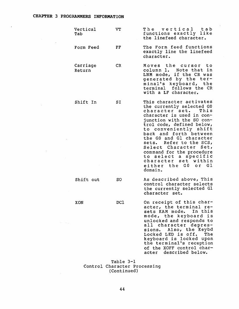
VerticalTab
Form Feed
CarriageReturn
Shift In
Shift out
XON
VT
FF
CR
51
so
DCl
The vertical tabfunctions exactly likethe linefeed character.
The Form feed functionsexactly line the linefeedcharacter.
Moves the cursor tocolumn 1. Note that inLNM mode, if the CR wasgenerated by the terminal's keyboard, theterminal follows the CRwith a LF character.
This character activatesthe currently selected GOcharacter set. Thischaracter is used in conjunction with the SO control code, defined below,to conveniently shiftback and forth betweenthe GO and Gl charactersets. Refer to the SCS,Select Character Set,command for the procedureto select a specificcharacter set withineither the GO or Gldomain.
As described above, Thiscontrol character selectsthe currently selected Glcharacter set.
On receipt of this character, the terminal resets KAM mode. In thismode, the keyboard isunlocked and responds toall character depressions. Also, the KeybdLocked LED is off. Thekeyboard is locked uponthe terminal's receptionof the XOFF control character described below.
Table 3-1Control Character Processing
(Continued)
44
CHAPTER 3 PROGRAMMERS INFORMATION
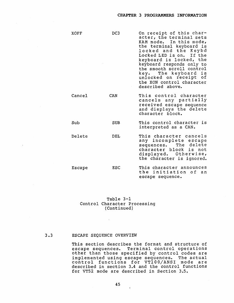
XOFF
Cancel
Sub
Delete
Escape
DC3
CAN
SUB
DEL
ESC
On receipt of this character, the terminal setsKAM mode. In thi s mode,the terminal keyboard islocked and the KeybdLocked LED is on. If thekeyboard is locked, thekeyboard responds only tothe smooth scroll controlkey. The keyboard isunlocked on receipt ofthe XON control characterdesc r ibed above.
This control charactercancels any partiallyreceived escape sequenceand displays the deletecharacter block.
This control character isinterpreted as a CAN.
This character cancelsany incomplete escapesequences. The deletecharacter block is notdisplayed. Otherwise,the character is ignored.
This character announcesthe initiation of anescape sequence.
Table 3-1Control Character Processing
(Continued)
3.3 ESCAPE SEQUENCE OVERVIEW
This section describes the format and structure ofescape sequences. Terminal control operationsother than those specified by control codes areimplemented using escape sequences. The actualcontrol functions for VT100jANSI mode aredescribed in section 3.4 and the control functionsfor VT52 mode are described in Section 3.5.
45
CHAPTER 3 PROGRAMMERS INFORMATION
3.3.1 Standards
The ASCII code structure used by the terminal isdefined by ANSI Standard X3.4-l977. Controlfunction communication is accomplished using asubset in accordance with ANSI Standard X.3.641979.
3.3.2 Control Sequen~e Format
In ANSI(VTlOO) mode, the terminal uses either twocharacter control sequences or multiple character(more than two) control sequences.
In VT52 mode, the terminal uses two charactercontrol sequences or in one command only (Di rectCursor Address) a four character sequence. Twocharacter control sequences use the form:
ESC F
Where ESC is the escape character (lBH) and F is asingle character indicating the control function.
The Direct Cursor Address uses the following form:
ESC Y line column
Where ESC is the escape character, Y is the ASCIIcharacter Y and line and column are each singleASCII characters representing the line and column,respectively.
In VT100 mode, mUltiple character escape sequencesare used in communicating to and from theworkstation a number of more complex commands andto indicate that certain keys were struck at thekeyboard. The possible formats for mUltiplecharacter control sequences are:
a. ESC [ PI; P2 Fb. ESC ( Pc. ESC) Pd. ESC i N
Form a is the most commonly used. ESC is theescape character (lBH), [ is the left bracketcharacter (5BH), PI is an ASCII character sequence(and possibly preceded by the ? character) whichrepresents a decimal number, ; is the semicoloncharacter (3BH) which acts as a parameterdelimiter for the next parameter P2 which followsand F is a single final character indicating the
46
CHAPTER 3 PROGRAMMERS INFORMATION
specific function to be performed. Again, the Piare command parameters, separated by semicolons.For this form, in many cases a parameter may benull or the sequence may not contain anyparameters. For example, the cursor positioncommand may take the following forms:
ESCESCESCESC
PI i P2 Hi P2 HPI HH
same assame assame as
ESC [ 0 ; P2 HESC [ PI ; 0 HESC [ 0 ; 0 H
Forms band c are used to specify a particular GOand Gl character sets, respectively. The (character is the left parenthesis (28H), ) is theright parenthesis (29H) and P is an ASCIIcharacter representing a character set choice.
Form d is used to specify double height/doublewidth lines or to specify the Screen AlignmentDisplay command. The * character is the poundsign character (23H).
An escape sequence is restricted to less than 29ASCII characters.
Command processing is aborted if incorrect syntaxor an illegal parameter is detected. The terminalresumes character processing after the characterwhich induced the error condition. An incompletecontrol sequence may be cancelled by transmittingthe CAN (18H) or DEL (7FH) control characters.
3.4 ANSI (VT100) CONTROL SEQUENCES
The following sections describe the multicharacter control sequences applicable to theterminal while it is in VT100 mode. Forreadability, the commands are presented in thefollowing order: the partition commands, thecursor movement commands, the edi t commands andthen all the remaining commands. Appendix I is analphabetical list of the commands by commandterminator.
Each command section is headed by the commandmnemonic, the command name and the permissibleformats. Unless otherwise stated after a command,the direction of command communication is from thehost processor to the terminal.
47

CHAPTER 3 PROGRAMMERS INFORMATION
3.4.1 PSR - Partition Screen
Formats: ESC [ PI PESC [ P
PSR divides the 25 physical lines of the screeninto two logical groups called partitions. Apartition may consist of n lines ( n greater thanor equal to 0 but less than or equal to 25) andthe other partition must contain 25-n lines.Partition 0 is the top group of lines andpartition 1 is the bottom group. If PI is null or0, partition 0 consists of the complete 25 linescreen and partition 1 will consist of a 0 line(null) screen. If PI is not null or not 0, thenPI is the first line of partition 1. Thus,partition 0 contains Pl-l lines and partition 1contains 25-Pl+l lines. A partition is selectedusing the SSPR command. If an illegal partitionis requested, the command is ignored. The stateof the terminal after command execution is as
-follows:
a. The screen is erased;b. Partition 0 is selected;c. The cursor is moved to the horne position;d. The scroll regions are set to the partition
.boundaries and ORIGIN mode is reset;e. The graphic rendition of each partition is
set to normal;f. Each line in the partition is set to normal
height and width;g. The Standard character set is activated; and,h. The tabs are reset to every eighth position,
beginning at character position nine.
Smooth scrolling only occurs in a partitioncontaining two or more lines.
Example: ESC [ 11 P will divide the screensuch that the top partition contains 10lines and the bottom partition contains15 lines.
3.4.2 SSCRL - Set Scroll Area
Formats: ESC [ PI ; P2 rESC [ i P2 rESC [ i rESC [ r
SCRL defines the scroll region within the selectedpartition. If the cursor is within or at the
48

CHAPTER 3 PROGRAMMERS INFORMATION
boundaries of the scroll region, cursor movementand scrolling is restricted to within this regionindependent of the state of ORIGIN mode. Howeverwhen ORIGIN mode is reset, the direct cursorcommand, CUP, may move the cursor with respect tothe partition origin and not the scroll origin;and therefore, the cursor may be moved outside ofthe scroll region. Also, when ORIGIN mode isreset the Cursor Position Report, CPR, yieldscoordinates with respect to the partition origin.If ORIGIN mode is set, then CUP moves the cursorwith respect to the scroll region and thereforethe cursor cannot be moved outside the scrollregion. Also, if ORIGIN mode is set, CPR yieldscoordinates with respect to the scroll region.
If a parameter is null or zero it is transformedto 1, the first line of the scroll region. PI isthe top line number of the scroll region and P2 isthe bottom line number. If both parameters arenull or zero, the scroll area is reset to the fullpartition. In any case, ORIGIN mode is alwaysreset and the cursor is moved to the partitionorigin. For this command to be honored, the sizeof the scroll region must be at least 1 line;although the region must contain 2 or more linesif smooth scroll is to occur.
Example: Partition 1 is selected and contains 15lines numbered from 1 through 15. Thecommand ESC [ 3; 15 r will subdividethe parti tion into a 13 line scrollregion with 2 lines fixed above and nofixed lines below. If ORIGIN mode isreset, the lines are numbered from 3 to15 within the scroll region; if ORIGINmode is set, they are numbered from 1 to13.
3.4.3 SSPR - Select Partition
Formats: ESC [ PI sESC [ s
SSPR selects or activates a specified partition.If PI is 0 or null, partition 0, the topparti tion, is selected;. if PI is 1, parti tion 1 isselected. Other vales of PI are ignored. When apartition is selected the cursor position, thecharacter set, the graphic rendition and the stateof ORIGIN mode are restored to their values whenthe partition was deselected. For convenience, ao line partition may be selected. Of course, anycharacters sent to the terminal are ignored.
49
CHAPTER 3 PROGRAMMERS INFORMATION
3.4.4 CUB - Cursor Backwards
Format: ESC [ PI DESC [ D
CUB moves the cursor left PI character positions.If PI is 0 or null, a move of 1 is attempted. Ifthe active line has the double width attribute,then the cursor moves left two times thatnumber of physical screen character positions. Ifthe number of character positions specified forthe move is greater than the current cursor columnposition, then the number of character positionsis truncated so as to move the cursor to column 1.
Example: The cursor is at column 2 of row 10.ESC [ 0 D backspaces the cursor tocolumn I of row 10.
3.4.5 CUD - Cursor Down
Formats: ESC [ PI BESC [ B
CUD moves the cursor down the number of rowsindicated by Pl. If PI is 0 or null, a move downof 1 is attempted. If the cursor is currentlyabove or within the scroll region, the move isconfined to that region. And if PI is greaterthan the number of lines below the active line tothe scroll reg ion bottom boundary, the cur so rmoves to the bottom line of the scroll region. Ifthe cursor is below the scroll region the moveoccurs unless PI is greater than the number oflines below the active line to the bottompartition boundary. In this case, the cursormoves to the bottom partition boundary. If anyintervening lines have the double heightattribute, a move down of PI lines moves thecursor down exactly that number of physical lines.
Example: The selected partition contains 10lines. The scroll region starts at line2 (counting from I) and ends at line 8with respect to the partitionboundaries. The cursor is at line 2 ofthe scroll region. ESC [ 20 B movesthe cursor to line 8 (the last line ofthe scroll region) with respect to thepartition.
50
CHAPTER 3 PROGRAMMERS INFORMATION
3.4.6 CUF - Cursor Forwards
Formats: ESC [ PI CESC [ C
CUF moves the cursor right PI positions. If PI iso or null, a move of I character position isattempted. For 1 ines having the single widthat t r i bu t e t his mea nsIphy sic a 1 c h a r act e rposition; and, for lines having double widthattribute this means 2 physical characterpositions. If PI is greater than the number ofcharacter positions to the right of the cursor,the cursor moves to the last character position onthe screen. For lines having the single widthattribute, this is character position 80, physicalposition 80; for lines having the double widthattribute, this is character position 40, physicalposi tion 79.
Example: The cu r sor i s at physical column 5, row10. The line is a double width line.ESC [C advances the cursor to columnphysical column 7 of the same line.
3.4.7 CUU - Cursor Up
Formats: ESC [ PI AESC [ A
CUU moves the cursor up PI rows. If PI is 0 ornull, a move of I is attempted. If the cursor iscurrently at or below the top boundary of thescroll region the move is performed, although anym~ve is truncated so as not to move past the topboundary of the scroll region. However, if thecursor is currently above the top boundary of thescroll region the move is done, although the moveis now truncated so as not to move past the topboundary of the partition.
Example: The cursor is at line 10 of partition 1.ESC [ 8 A will move the cursor toline 2 of partition 1.
3.4.8 CUP - Cursor Position
Formats: ESC PI ; P2 HESC PI ; HESC ; P2 HESC PI HESC H
CUP moves the cursor to a specified row and columnnumber within the active partition. The first
51
CHAPTER 3 PROGRAMMERS INFORMATION
coordinate is the row number and the secondcoordinate is the column number. The top halfand the bottom halves of double height lines eachcount as one unit. But for double width lines thecolumn number means the character position. Thus,for this command the actual physical column position on the screen for P2 is 2*(P2)-1. If ORIGINmode is reset, then the move is with respect tothe partition origin; if ORIGIN mode is set, thenthe move is with respect to the scroll regionorigin. A parameter value of 0 or null istreated as 1. If any parameter is such that themove is outside the appropiate boundary, the moveis truncated so as to move to that boundary.
Example: Partition 0 contains 10 lines numbered 1to 10. The scroll area begins at line 2and ends at line 9. ORIGIN mode is set.ESC [H homes the cursor to row 1,column 1 of the scroll region. This isline 2, column 1 with respect to thepartition boundaries.
3.4.9. CPR·- Cursor Position Report
Format: ESC [ PI ; P2 R (Terminal to host)
CPR is a data sequence used to report the cursorposition to the host. The report is requested bythe host using the DSR request (Device StatusReport) with option PI set to 6. The cursorresponds using the CPR sequence described in thissection. PI is the row number and P2 is thecolumn number. If ORIGIN mode is reset, thecoordinates returned are with respect to thepartition origin. If ORIGIN mode is set, thecoordinates returned are with respect to thescroll region origin. Leading zeros are alwayssupressed. The first row or column number iscalled 1. For double width lines, the characterposition rather than the actual column position isreturned.
Example: Partition 0 contains a scroll regionembedded within the partition. ORIGINmode is reset. The cursor is at horne.The cursor position is requested by:ESC [ 6 n. The terminal responds withESC [ 1 ; I R.
52
CHAPTER 3 PROGRAMMERS INFORMATION
3.4.10 CURSV - Cursor Save
Format: ESC 7
This command saves the partition's current cursorposition, graphic rendition, the character setclass and the SCS character set within the class.These parameters may be restored by the CURRS(Cursor Restore) command described in the nextsection.
Example: The cursor is currently at row 10,column 5. Bold character rendition iscurrently active as well as analternate character set. The sequenceESC 7 is transmitted to the terminal tosave the above mentioned parameters.Later, after the cursor position as wellas the selected character set haschanged, the command ESC 8 is given.The cursor returns to row 10, column 5and the alternate character set isreactivated.
3.4.11 CURRS - Cursor Restore
Format: ESC 8
The Cursor Restore command restores thepartition's cursor position, graphic rendition andcharacter set previously saved by the Cursor Savecommand described in the previous section.
Example: The cursor was at row 10, column 5 whenthe sequence ESC 7 was sent to theterminal. After the cursor has beenmoved, the sequence ESC 8 is sent to theterminal. The cursor moves back to row10, column 5.
3.4.12 HVP - Horizontal and Vertical Cursor Position
Formats: ESC [ PI ; P2 fESC [ PI ; fESC [ ; P2 fESC [ PI fESC [ f
HVP functions identically to the CUP (CursorPosition) command.
53
CHAPrER 3 PROGRAMMERS INFORMATION
3.4.13 INDX ~ Index
Format: ESC D
This command is treated exactly like a linefeedcharacter.
3.4.14 NXTLN - Next Line
Format: ESC E
This command is~equivalent to a linefeed followedby a carriage return.
3.4.15 RIND - Reverse Index
Format: ESC M
RIND acts like a reverse (backwards) linefeed. Ifthe active cursor position is below or within thescroll region, the RIND command moves the cursorup one position unless the cursor is already atthe top scroll region boundary. In this case, thecursor does not move but the scroll region scrollsdown one line. That is, all the current lineswithin the scroll region move down 1 position, theoriginal bottom line is lost, and the top line ofthe scroll region is erased. If the active cursorposition is above the scroll region, but not atthe top partition boundary, the cursor moves upone line position. If the cursor is at the toppar tit ion b 0 un dar y , no act ion. 0 c cur s • T hiscommand is not affected by the state of LNM mode.
Example: Parti tion 1 is selected. The scrollregion starts at line 2 and ends at line4 within this partition. The cursor iscurrrently at line 2 when the sequenceESC M is received by the terminal.Lines 2 through 4 move down one lineposi tion, leaving a blank line in placeof the original line 2 and the originalline 4 is lost and replaced by theoriginal line 3.
3.4.16 DCH - Delete Character in Line
Formats: ESC [ PI PESC [ P
DCH deletes PI characters of the active line. Ifthe active line has the double width attribute,then 2*Pl physical characters are deleted. Thecharacters starting from the cursor position,inclusive and going from left to right are
54

CHAPTER 3 PROGRAMMERS INFORMATION
deleted. The characters remaining on the line areshifted left filling up the vacancies created bythe deleted characters. The vacated characterpositions on the right are erased. If PI is 0 ornull, one character is deleted. If morecharacters are specified than remain on the line,then the remainder of the line is erased.
Example: The cur sor is at column 78; the Graphi cRendition of character position 78, 79and 80 is reverse video. ESC [ 2 Pmoves the reverse video characters atcolumn 80 to column 78. Positions 79and 80 are set to normal video blanks.
3.4.17 ICH - Insert Character in Line
Formats: ESC [ PI @ESC [ @
ICB inserts PI prime rendition blanks at theactive posi tiona If the line's current attributeis double width, then 2*Pl blanks are inserted.The characters beginning at and to the right ofthe active position are shifted right PI characterpositions.
Characters shifted off the screen are lost. If PIis 0 or null, 1 character is inserted. If PI isgreater than the number of characters to the rightof the cursor, only that number of blanks areinserted. This command does not change the cursorposition.
Example: The cursor is at column 1. ESC [ 0 @shifts all the characters on the active1 i ne 1 po sit i on rig h t ; the c h a rae t e rpreviously at column 80 is lost andcolumn 1 contains a blank.
3.4.18 DL - Delete Line
Formats: ESC [ PI MESC [ M
DL deletes PI lines from the current scrollregion. If VEM mode is reset, then PI lines fromthe active line, inclusive, down are deleted; theremaining lines are moved up and the vacanciesreplaced by prime rendition blank lines. If PI isgreater than the number of lines remaining in thescroll region, the remaining lines are deleted.If VEM mode is set, the PI lines from the activeline, inclusive, up are deleted; the remaininglines at the top of the scroll region are moved
55

CHAPTER 3 PROGRAMMERS INFORMATION
down and the vacancies replaced by prime renditionblank lines. If PI is null or 0, - one line isdeleted. If PI is greater than the number oflines between the top of the scroll region and theactive line, then that number of lines is deleted.Note that double height lines count as two linesas always. If the cursor is currently outside thescroll region, the command is ignored. If theuser desires to delete lines outside the scrollregion, the scroll region first must be set to thepartition boundaries or at least must include theedit lines using the SSCRL command.
Example: The scrolling region contains lines Ithrough 10; the active line number is 2;VEM mode is reset. ESC [ 3 M deleteslines 2 ,3 and 4; lines 5 through 10move up 3 rows; and the original lines8, 9 and 10 are erased.
3.4.19 IL - Insert Line
Formats: ESC [ PI LESC [ L
IL inserts PI lines at the active line. If VEMmode is reset, PI lines containing all primerendition blanks are inserted at and below theactive line. Lines pushed passed the bottomscroll region boundary are lost. If VEM mode isset, PI lines containing all prime renditionblanks are inserted at and above the active line.Lines from and including the active line arepushed up. Lines pushed up past the top scrollregion boundary are lost. In either case, thecursor does not move.
If PI is 0 or null, I line is inserted. If PI isgreater than the number of lines remaining fromthe active line to the bottom scroll boundary, inthe case VEM mode is reset or the number of linesfrom the top scroll boundary to the active line,in the case VEM mode is set, then that number isused for Pl.
If the cursor is currently outside the scrollregion, this command is ignored. To insert a lineoutside the scroll region, use the SSCRt command.The scroll region first must be set to thepartition limits or at least must include the editlines. The scroll region may then be reset toits former boundaries.
Example: The selected scroll region contains 10lines. The active line is line 4; VEM
56

CHAPTER 3 PROGRAMMERS INFORMATION
mode is set. ESC [L moves lines 2through 4 up one row; the original topline is lost and line 2 is now at thepartition top. The original line 4 iserased.
3.4.20 EL - Erase in Line
Formats: ESC [ PI KESC [ K
EL erases part or all of the active line. Erasuremeans setting the specified area to primerendition blanks. Three variations of thiscommand are defined:
PI
o or null
I
2
A~ION
Erase f"rom the cu r so r posi ti on,inclusive, to the end of the activeline.
Erase from the beginning of theactive line to the active cursorposition, inclusive.
Erase the entire active line. Ifthe current line was defined asei ther top half or bottom half of adouble height line, it will remainso defined.
In each of the above cases, the cursor positiondoes not change after command execution.
Example: The cursor is at column 10. ESC [ 1 Kerases characters 1 through 10,inclusive, of the active line.
3.4.21 ED Erase in Display
Formats: ESC [ PI JESC [ J
ED erases a specified portion of the screen.Erasure means setting the specified area to primerendition blanks. The erasure limits for thiscommand are determined by the Active EditBoundaries. The Active Edit Boundaries aredependant upon both the states of both ORIGIN andEDIT modes. If ORIGIN mode is reset, independantof the state of EDIT mode, the Active EditBoundaries are the partition boundaries. IfORIGIN mode is set, the Active Edit Boundaries are
57

CHAPTER 3 PROGRAMMERS INFORMATION
the partition limits if EDIT mode is reset or thescroll boundaries if EDIT mode is set.
Three variations of this command are defined:
~ ACTION
o or null Erase from the current cursorposition, inclusive, to thelower Active Edit Boundary.
1 Erase from the top Active EditBoundary to the cursor position, inclusive. The cursordoes not move.
2 Erase the entire Active Editregion; that is, the areabetween the top line to thebottom line of the Active EditBoundaries The cursor doesnot move in this command.Also, if lines within theActive Edit Boundaries had theattribute of double height,either top half or bottomhalf, they are redefined ashaving normal height/widthattributes.
Example: The cursor is at line 2, column 10 inthe scroll region. ESC [ 2 J erases alllines within the partition. The cursordoes not move.
3.4.22 DA - Device Attributes
Formats: ESC [ PI cESC [ ?l ; 2 c
(Host to terminal)(Terminal to host)
The DA command with PI option equal to null orzero is used by the host to request the terminalsDevice Attributes report. The terminal alwaysresponds with the report ESC [ ? I ; 2 c.
58
CHAPTER 3 PROGRAMMERS INFORMATION
3.4.23 DSR - Device Status Report
Formats: ESC [ 0 nESC· [ 5 nESC [ 6 n
(Terminal to host)(Host to terminal)(Host to terminal)
The DSR command is used by the host to requesteither the terminal position or the terminalstatus.
The options are described by the following table:
.ll
o
5
PIRECTION
Terminal to Host
Host to terminal
ACTION
This is a response to thestatus request using PIequal to 5 describedbelow. A response withPI equal to 0 impl ies theterminalis available toprocess commands.
This is a request by thehost for the terminalstatus. The onlyresponse is PI equal to0, indicating theterminal is ready.
Example 1:
Host to terminal6
Example 2:
This is a request by thehost for the currentcursor position. Theterminal responds usingthe CPR, Cursor PositionReport.
The host transmits ESC [ 5 n to theterminal; the terminal respondswith ESC [ 0 n indicating theterminal is ready.
The host transmits ESC [ 6 nrequesting the cursor position; theterminal responds with the CPRsequence: ESC [ 0 ; 0 R. Thissequence indicates the cursor is inthe home position.
59

CHAPTER 3 PROGRAMMERS INFORMATION
3.4.24 HTC ~ Horizontal Tabulation Set
Format: ESC H
HTC sets one horizontal tab stop at the currentcursor character position. Thus if afterwards thecurrent cursor position is to the right of thisset position and the terminal recieves a TAB, thecursor moves to that tab stop. The maximum numberof tab stops is 16; and, any attempt to setadditional tabs stops is ignored. Incidentally,there is always an automatic tab set at the lastcharacter position of a line. This is physicalposition 80 for single width lines and physicalposition 79 for double width lines. Tabs arecleared either individually or totally by the TBC,Tabaulation Clear command.
Example: The current line width attribute isnormal. The cursor is at column 5. Thefollowing sequence is sent to theterminal: ESC [ 3 g ESC H CR HT. Thecursor moves to column 1 and then backto column 5.
3.4.25 ID - Identify
Format: ESC Z
This command requests the terminal'sidentification sequence. The command illicits theexact same response as the DA request (DeviceAttributes). For a number of reasons, it isrecommended for new applications that the userrefrain from using this command and instead usethe DA command.
Example: The host sends ESC Z to the terminal;the terminal responds with ESC [ ?l 2 c
3.4.26 KEYAPP - Enter Keypad Application Mode
Format.: ESC =
This command sets the keyboard into the keypadapplication mode. In this mode, the non functionkeys on the auxiliary keypad generate differentcode sequences than in the numeric mode. That is,the keys send three character code sequences tothe host when struck. Refer to Appendix D for theexact code sequences transmitted.
60
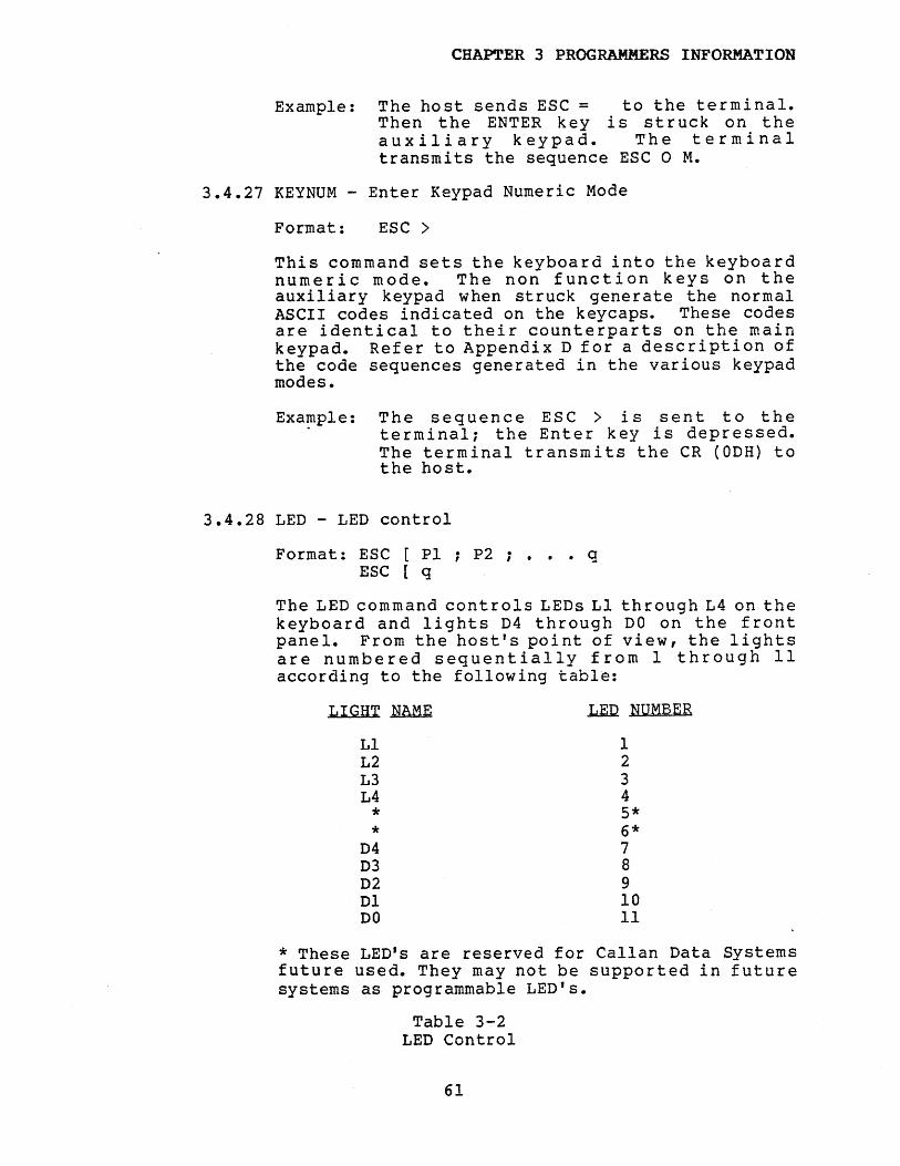
CHAP'l'ER 3 PROGRAMMERS INFORMATION
Example: The host sends ESC = to the terminal.Then the ENTER key is struck on theauxiliary keypad. The terminaltransmits the sequence ESC 0 M.
3.4.27 KEYNUM - Enter Keypad Numeric Mode
Format: ESC >
This command sets the keyboard into the keyboardnumeric mode. The non function keys on theauxiliary keypad when struck generate the normalASCII codes indicated on the keycaps. These codesare identical to their counterparts on the mainkeypad. Refer to Appendix D for a description ofthe code sequences generated in the various keypadmodes.
Exa~ple: The sequence ESC > is sent to theterminal; the Enter key is depressed.The terminal transmits the CR (ODH) tothe host.
3.4.28 LED - LED control
Format: ESC [ PI ; P2 ; • • • qESC [ q
The LED command controls LEDs Ll through L4 on thekeyboard and lights D4 through DO on the frontpanel. From the host's point of view, the lightsare numbered sequentially from 1 through 11according to the following table:
LIGHT~
LlL2L3L4**
D4D3D2DlDO
.L.EI! NUMBER
12345*6*7891011
* These LED's are reserved for Callan Data Systemsfuture used. They may not be supported in futuresystems as programmable LED's.
Table 3-2LED Control
61
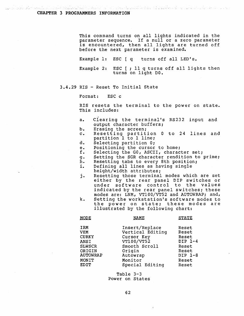
CHAPTER 3 PROGRAMMERS INFORMATION
This command turns on all lights indicated in theparameter sequence. If a null or a zero parameteris encountered, then all lights are turned offbefore the next parameter is examined.
Example 1: ESC [ q turns off all LED's.
Example 2: ESC [ ; 11 q tu rns off all 1 ight s thenturns on light DO.
3.4.29 RIS - Reset To Initial State
Format: ESC c
RIS resets the terminal to the power on state.This includes:
a. Clearing the terminal's RS232 input andoutput character buffers;
b. Erasing the screen;c. Resetting partition 0 to 24 lines and
partition I to 1 line;d. Selecting partition 0;e. Positioning the cursor to home;f. Selecting the GO, ASCII, character set;g. Setting the SGR character rendition to prime;h. Resetting tabs to every 8th position;i. Defining all lines as having single
height/width attributes;j. Resetting those terminal modes which are set
either by the rear panel DIP switches orunder software control to the valuesindicated by the rear panel switches; thesemodes are: LNM, VT100/VT52 and AUTOWRAPi and,
k. Setting the workstation's software modes tothe power on state; these modes areillustrated by the following chart:
STATE
IRMVEMCURKYANSISLWSCRORIGINAUTOWRAPMONITEDIT
Insert/ReplaceVertical EditingCursor KeyVT100/VT52Smooth ScrollOriginAutowrapMonitorSpecial Editing
Table 3-3Power on States
62
ResetResetResetDIP 1-4ResetResetDIP 1-8ResetReset

CHAPTER 3 PROGRAMMERS INFORMATION
3.4.30 SM - Set Mode
Format: ESC [ PI ; P2 ; h
The SM command and the RM command described in thenext section are designed to be used together toset and reset a number of terminal modes whichalter the terminal's behavior. The command setsswitches which are described in the followingsections. As indicated by the format, mUltipleswitches may be set with a single command. If aparameter is null or 0, it is ignored duringcommand processing.
3.4.31 RM - Reset Mode
Format: ESC [ PI ; P2 ; P3 ; • • • 1
The RM command and the SM command described in theprevious section are designed to be used togetherto set and reset a number of te rminal modes. Thi scommand resets the terminal modes indicated by theparameters PI, P2 ••• , etc.
As indicated by the format, multiple modes may beset using a single command. Any null or 0parameter encountered during command processing isignored. The description of the modes follows inthe next section.
3.4.32 Mode Description
Any or all of the modes may be simultaneously setor reset by using the Set and Reset Mode commands,respectively.
A mode is specified by a decimal ASCII string.Certain modes must be preceded by the questionmark (3FH). A number of the modes described inthe following sections are initialized duringpower up or by execution of the RIS commandaccording to settings of the rear panel DIPswitches. These modes are: LNM mode, ANSI modeand AUTOWRAP. The other modes described here arenot affected by the rear panel DIP switches. Inthe mode descriptions which follow, the specifyingparameter is enclosed in parenthesis following themode mnemoni c.
63

CHAPTER 3 PROGRAMMERS INFORMATION
IRM (4) - Insert/Replace Mode
In the reset (default) state, a received characterreplaces the character at the active cursorposition. In the set state, a received characteris inserted at the active position. Thus, in thisstate, the characters beginning at and to theright of the active position are shifted right 1character position. The rightmost character islost. For double width characters, the appropiatecharacter is inserted followed by a primerendi tion blank.
Example: The act i ve 1 i ne beg i ns with the thephrase: The line begins •••• Thecursor is at cursor columnposition, 5. The sequence ESC [ 4hac t i v e SP is sent tothe terminal. The active line nowappears as follows: The activeline begins •••••
VEM (7) - Vertical Editing Mode
The Vertical Editing Mode affects theinsert and delete line commands, IL andDL, respectively. The power up state ofVEM is reset. In this state, lines aredeleted from the active line down by theDL command and the active line down ispushed down by the IL command.
If VEM is set, lines are deleted fromthe active line up by the DL command andthe active line up is pushed up by theII command.
Example: ESC [ 4 ; 7 1VEM mode.
resets IRM and
LNM (20) - Linefeed/New line mode
When this mode is reset, the linefeedand carriage returns are processed as iseither when received from the hostcomputer or generated by the keyboard.If LNM mode is set, the terminal followskeyboard generated carriage returns withlinefeeds on transmission to the hostand generates a carriage after receivinga linefeed. This mode is initializedupon power up or by execution of the RIScommand according to the setting of rearpanel DIP switch 1-6.
64
CHAPTER 3 PROGRAMMERS INFORMATION
Example: The host sends ESC [ 20 h tothe terminal. The auxiliarykeypad is in numeric mode.When the ENTER key isdepressed, the carriagereturn/linefeed sequence isalways generated.
CURKY (?l) - Cursor Key Mode
When this mode is reset, the four cursorcontrol keys on the keyboard send theappropriate escape sequences which, ifechoed by the host computer, move thecursor according to the directionsindicated on the keycaps. The resetstate is the power up state. When thi smode is set, the cursor keys senddifferent sequences. Refer to appendixG for the exact codes sent.
Example: The sequence ES C [ ? 1 hissent to the terminal; the userstrikes the up arrow key. Theterminal responds with ESC 0A.
ANSI (?2) - VT100/VT52 Mode
In the reset state, the terminalinterprets command sequences accordingto the VT52 format described herein. Inthe set state, the terminal interpretscommands according to the VT100 format.This mode is initialized on power up orwhen the RIS command is executedaccording to the setting on the rearpanel DIP switch 1-4.
Example: Rear panel DIP switch 4 is inthe off position. Thesequence required to set afull 25 line partition andreturn to VT52 mode is asfollows: ESC < ESC [ P ESC (?2 1.
65

CHAP'.rER 3 PROGRAMMERS INFORMATION
SLWSCRL (14) - Slow Scroll Mode
If SLWSCRL is reset, the power up state,the terminal executes jump scroll asdescribed in the section on Slow ScrollConsiderations. If this state is set,then the terminal scrolls smoothly andslowly. The state of SLWSCRL is toggledby the scroll control key on thekeyboard. Thus, the user may change thestate of SLWSCRL which was set by thehost software by depressing that key.Another situation where the SLWSCRLstate is altered without a host commandis if the terminal is currently in asmooth scroll mode and a partition isselected having less than two lines,then SLWSCRL is reset.
Example: The sequence ESC [ 14 h issent to the terminal. Theterminal is in the smooth slowscroll mode.
ORIGIN (16) - Origin Mode
ORIGIN mode defines the origin used forthe absolute cursor positioning,reporting and the erasure commands.When this mode is reset, the defaultstate, the cursor moves to the partitionorigin which then is the origin for theCUP, HVP and CPR commands. When ORIGINmode is set, the cursor moves to thescroll region origin which then is theorigin for those commands. Also, ifORIGIN and EDIT modes are set, thenerasure, as defined by the ED command,is with respect to the scroll region.Whether or not ORIGIN mode is set orreset, scrolling is always confined tothe scroll region.
Example: The command sequence ESC [ 16h moves the cursor to theupper left corner of thescroll region.
66
CHAPTER 3 PROGRAMMERS INFORMATION
AUTOWRAP (17) - Autowrap Mode
AUTOWRAP mode determines the action ofthe cursor when the cursor is at thelast character position of a line. Thisis character position 80, physicalposition 80 for single width lines andcharacter position 40, physical position79 for double width lines. Suppose adisplayable character was previouslysent to this position. If Autowrap isreset and another displayable characterfollows then this character overlays thelast character. If Autowrap is set anda displayable character follows, thenthe terminal executes an automaticcar ria gere t u r nj 1 in e fee d be for eprocessing the second character. Thei nit i a 1 s tat e 0 f AUT 0 WRAPis setaccording to the sense of rear panel DIPswitch 1-8 when power is fir s tapp1 i e dor whenever the RIS command is executed.
Example: AUTOWRAP mode is set. Thecursor is currently at line 2column 79 when the followingsequence is sent to theterminal: 1 2 3. The 1 isdisplayed on line 2, column79; the 2 is displayed on line2, column 80; and the 3 isdisplayed on line 3, column 1.The cursor is currently atline 3, column 2.
MONIT (190) - Monitor Mode
Moni tor mode determines the terminal'sresponse to the 33 control characters(OOH to IFH and 7FH). When this mode isreset, the default state, receivedcontrol characters implement theircontrol function and are not displayed.When this mode is enabled, the controloperation is not implemented but anassociated graphic character isdisplayed. Appendix A contains thegraphics associated with controlcharacters assuming the standardchar acte r ROM is used. The g r aphi ccharacters used in the standardcharacter ROM are the ones stored in thefirst 32 locations of the ROM (andlocation 7F Hex) and are therefore thesame ones used for the GO, Special
67

CHAPTER 3 PROGRAMMERS INFORMATION
Graphics character set. It is noticedfrom Appendix A that the graphicsdisplayed are not always indicative ofthe control characters sent. Forexample, the graphic displayed forlinefeed is VT! If extensive debuggingis required, perhaps the user may burn amore appropriate PROM having morerepresentative graphics for the 32control characters. Refer to Section4.3 for the required procedure.
Obviously, MONITOR mode can not be resetby the host computer. The user mayreset MONIT mode by toggeling the scrollcontrol key on the keyboard.Alternatively, he may recycle power tothe terminal.
Example: The host sends the sequenceESC [ ?90 h to the terminal;the linefeed character (OAB)is followed. The terminaldisplays the VT graphic.
EDIT (?91) - Special Erasure Edit Mode
EDIT mode determines the bounds oferasure for the ED command. If eitherORIGIN or EDIT mode is reset, erasure isalways with respect to the partitionboundaries. But if both ORIGIN and EDITmodes are se.t, than erasure i sw i threpect to the scroll boundaries.
Example: The scroll region begins atrow 6 and ends at row 10,inclusive. The terminalreceives the followingsequence: ESC [ ?6 ; ?91 hESC [ 2 J. The entire scrollregion and only the scrollregion is erased.
3.4.33 SDHL - Set Double Height/Width Line
Format: ESC * 3ESC * 4
(Set top half)(Set bottom half)
The above sequences assign either top half orbottom half, respectively, the double height/widthattributes to the active line. The sequences aredesigned to be used in pairs on adjacent lines andthe same character output should be sent to both
68

CHAPTER 3 PROGRAMMERS INFORMATION
lines to form full double height characters. Ifthe line was single width/single height, allcharacters to the right of the center of thescreen are lost. The cursor remains over the samecharacter position unless it would be to the rightof the right margin, in which case it is moved tothe right margin. If the line attribute wasalready double height/width, the command isignored. The top half of a double height lineconsists of the character followed by a blank.The bottom half consists of the dash followed by ablank regardless of the character transmitted tothe terminal.
Example: The sequence ESC # 3 is sent to theterminal. The characters from physicalposition I through 40 are expandedthereby occupying position I through 80.The characters originally at physicalpositions 41 through 80 are shifted offthe screen and are lost.
3.4.34 SNHW - Set Normal Height/Width Line
Format: ESC # 5
This command assigns the normal height/widthattribute to a line. If the attribute previouslywas double width, ei ther double height/doublewidth or double width, then the current line iscompressed. All spaces between the characters areremoved. The line then consists of 40 characterson the screen, followed by 40 blanks. If theline's attribute was normal, no action occurs.
Example: The current line has the double widthattribute. The cursor is at characterposition 2, physical position 3. Thesequence ESC I 5 is transmitted to theterminal. The characters previously atphysical positions I, 3, 5, ••• etc.,are packed into positions 1,2,3, etc.Positions 41 through 80 are set toblanks. The cursor is moved to physicalposition, 2.
3.4.35 SDWL - Set Double Width Line
Format: ESC' # 6
This command assigns the attribute double width(only) to the active line. If the line previouslywas single height/single width, all characters tothe right of the screen are lost. The cursorremains over the same character position unless it
69

CHAPTER 3 PROGRAMMERS INFORMATION
would be to the right of the right margin, inwhich case, it is moved to the right margin. Ifthe line has the attribute double width already,the command is ignored.
3.4.36 SAD - Screen Alignment Display
Format: ESC # 8
This command fills the entire screen area withupper case "E"s. This pattern is useful forscreen alignment and adjustments. This command isequivalent to the host partitioning the screeninto partition 0 having 25 lines and partition Ihaving 0 lines, then transmitting 25 lines of"Ens. The cursor is then homed.
3.4.37 SCS - Select Character Set
Formats: ESC ( PIESC ) PI
The host processor may choose between fivecharacter sets. Three are stored in the primaryROM, supplied with the terminal, and twothe user may supply by programming an alternateROM. The GO or the Gl domain is activated by thehost processor sending the control codes SI and SO(Shift in and Shift out), respectively. In thepower up state, the GO domain is active and theASCII set is selected. The code sequencesrequired to select the various character sets ineach of the domains are described by the followingtable:
GO GlSEQUENCES SEQUENCES
SETCHOSEN
LOCATIONQF. CHARACTER ~
ESC ( A ESC ) A United KingdomESC ( B ESC ) B ASCIIESC ( 0 ESC ) 0 Special GraphicsESC ( I ESC ) 1 Alternate SetESC ( 2 ESC ) 2 Alternate
Special Graphics
Table 3-4Alternate Character Sets
70
Primary ROMPrimary ROMPrimary ROMAlt. ROMAlt. ROM
CHAPTER 3 PROGRAMMERS INFORMATION
Example: The sequence ESC (A ESC) 1 is sent tothe terminal. When the host sends theSI control character, the united Kingdomset is selected; when the host sends theSO control character, the Alternatecharacter ROM standard character set isselected.
3.4.38 SGR - Select Graphic Rendition
Formats: ESC PI i P2 ; P3 . . . mESC ; PI ; P2 . . . mESC PI . P2 . ; P3 . . . m, I
ESC m
The SGR command sets the rendition or auxiliaryattributes that are associated with the charactersas they are received and displayed. Theseattributes are described in the following table:
ATTRIBUTES
o or null145799
Primary RenditionBoldUnderlineSlow blinkReverse VideoOverstrike
The above attributes may be assigned individuallyor in any combination. If an undefined parameteris used in the command string, the command isignored. The attributes are accumulated fromcommand to command. That is, the attributesspecified by the command are logically anded tothe previous SGR rendition. However, if at anytime a null zero parameter is specified, theprimary rendition is restored.
The terminal uses the transparent attributephilosophy whereby the assignment of characterattributes do not .. consume character posi tions onthe screen. However, each line is restricted to15 rendition changes. If the active line alreadyhas 15 rendition changes and a character isreceived which would require an additionalrendition change, the character is laid into theline using the same graphic rendi tion as theoverlaid characters. In other words, the newgraphic rendition is not yet honored. This use ofthe new rendition resumes as soon as the conditionoccurs where the active line has less than 15rendition changes.
71
CHAPTER 3 PROGRAMMERS INFORMATION
Example: The sequence ESC [ I ; 0 ; 5 i 99 m issent to the teiminal. Henceforth allcharacters transmitted to the screenblink and are overstruck. Thecharacters do not have the attribute ofbold.
3.4.39 TBC - Tabulation Clear
Formats: ESC [ PI 9ESC [ g
TBC clears tab stops set by the HTC command. Twooptions are available: If PI is 0 or null, anyhorizontal tab stops at the current cursorcharacter position are removed. If PI is 3, allhorizontal tab stops are cleared. Other values ofPI are ignored. This command does not remove theautomatic tab stop at the last character positionof the line.
Example: The active line has normal height/widthattributes. Furthermore, a number oftab stops are currently set. The cursoris at column I when the sequence ESC [g TAB is received. The active positionis now column 80.
72
CHAPTER 3 PROGRAMMERS INFORMATION
3.5 VT52 CONTROL SEQUENCES
The following sections describe the controlsequences applicable to the terminal while it isin the VT52 mode. The host processor may use manyof the VT100 features such as select partitionboundaries, Set scroll region boundaries, selectcharacter set or SGR by using the VT52 command totransfer into the VT100 mode. Then after theappropriate VT100 commands have been executed, thehost uses the VT100 RM command with the ·?2 optionto switch the terminal back into the VT52 mode.
3.5.1 VANS - Enter VT100 Mode
Format: ESC <
This command switches the terminal into the VT100mode.
3.5.2 VENT - Enter Keypad Application Mode
Format: ESC =
This command sets the keyboard into the KeypadApplication mode. In this mode, the non functionkeys on the auxiliary keypad generate differentcode sequences than in the numeric mode. That is,these keys send three character code sequences tothe host when struck. The code sequences sent tothe host when the keypad is in VT52 KeypadApplication mode are different sequences when thekeypad is in VT100 Keypad Application mode.Refer to Appendix C for a description of thevarious keypad code sequences.
Example: The terminal is in VT52 KeypadApplication mode when the ENTER key isstruck on the auxiliary keypad. Theterminal transmits to the host thesequence ESC ? M.
3.5.3 VEXTA - Enter Keypad Numeric Mode
Format: ESC >
This command sets the keyboard into the KeyboardNumeric mode. The non function keys on theauxiliary keypad when struck generate the normalASCII codes indicated on the keycaps and which areidentical to their counterparts on the mainkeypad. Refer to Appendix C for a description ofthe code sequences generated in the various keypadmodes.
73
CHAPl'ER 3 PROGRAMMERS INFORMATION
Example: The sequence ESC > is sent to theterminal; The ENTER key is depressed.The terminal transmits the code ODa tothe host.
3.5.4 VUP - Cursor Up
Format: ESC A
This command moves the cursor up one lineposition. The cursor does not move past the topscroll or partition boundary. The restrictionsthat apply to the CUU command apply here also.
3.5.5 VDOWN - Cursor Down
Format: ESC B
This command moves the cursor down one lineposition. The cursor does not move past thebottom scroll or partition boundaries. Therestrictions that apply to the CUD command, applyhere also. '
3.5.6 VRIGHT - Cursor Right
Format: ESC C
This command moves the cursor right 1character position. The Restrictions that applyto the CUP command, apply here also.
3.5.7 VLEFT - Cursor Left
Format: ESC D
This command moves the cursor left 1 characterposition, if possible. If the cursor is alreadyat column 1, no action occurs. The attributes andrestrictions which apply to the CUF command, applyhere also.
3.5.8 VENTGR - Enter Graphic Character SetMode
Format: ESC F
This command activates the SpecialCharacter set. This is the same characterset activated by the VT100 command, ESC (o.
74
CHAPTER 3 PROGRAMMERS INFORMATION
Example: The sequence ESC F c displaysthe FF (Formfeed graphic) at theterminal.
3.5.9 VEXTGR - Exit Graphic Character SetMode
Format: ESC G
This command removes the terminal from theSpecial Graphics Character Set Mode.
3.5.10 VHOME - Home Cursor
Format: ESC H
This command returns the cursor to the homeposition. This command functions exactlylike the VT100 ESC [ H command sequence.
Example: The processor was previously executing aprogram in the VT100 mode. The scrollregion was different than the partition.Also, ORIGIN mode was set. The hostsends the terminal the followingsequence: ESC [ ? 2 e ESC H. TheWorkstation is now is VT52 mode andcursor homes to the upper left corner ofthe scro1~ region.
3.5.11 VREVLF - Reverse Linefeed
Format: ESC I
This command executes a cursor up movement.If the cursor is at the top line of theselected scroll region, a scroll downoccurs. This command functions identicallyto the RINDR command.
3.5.12 VEREOS - Erase to the End of Screen
Format: ESC J
This command erases the screen from the currentcursor position, inclusive, to the end of theActive Edit Boundary. This command functionsidentically to the ED command with PI set to 0 ornull.
75

CHAPTER 3 PROGRAMMERS INFORMATION
3.5.13 VEREOL - Erase to End of Line
Format: ESC K
This command erases the active line from thecurrent cursor position, inclusive, to the end ofthe line. This command functions identically tothe EL command wi,th PI set to 0 or null.
3.5.14 VDL - Delete Line
Format: ESC U
This command deletes the active line. Thecomments concerning VT100 VEM mode apply to thiscommand.
3.5.15 VIL - Insert Line
Format: ESC V
This command inserts a single prime rendition lineat the active line. The behavior of the editprocess as defined by the VT100 VEM mode, applyhere.
3.5.16 VCLRH - Clear Screen and Home Cursor
Format: ESC W
This command clears the Active Edit area,according to the VT100 mode flags and thenhomes the cursor.
Example: The terminal is placed in the VT100 modeto set both ORIGIN and EDIT modes. Ascroll region is defined within thecurrent partition. The followingsequence is sent to the terminal: ESC [?2 1 ESC W. The terminal is now in theVT52 mode, the scroll region is erasedand the cursor is moved to the upperleft corner of the scroll region.
3.5.17 VDIRC - Direct Cursor Address
Format: ESC Y line column
This command moves the cursor, within thepartition, to the absolute cursor positionspecified by the line and column. The first ASCIIcharacter after the Y represents the line numberand the second character after the Y representsthe column number. This command is independant ofORIGIN or EDIT modes, the move is always absolute
76
CHAPTER 3 PROGRAMMERS INFORMATION
with respect to the parti tion boundaries. Togenerate the ASCII character to represent acoordinate, add IF hexidecimal to the coordinatevalue. If a coordinate is specified which wouldmove the cursor off the selected partition, thenthat value is ignored and the current coordinateis retained.
Example: The command ESC Y ! ! positionsthe cursor to line 2, column 2 ofthe current partition.
3.5.18 VID - Identify
Format: ESC Z
This sequence instructs the terminal to respondwith the Identifier escape sequence. Thissequence is always ESC / Z.
77

CHAPTER 3 PROGRAMMERS INFORMATION
78
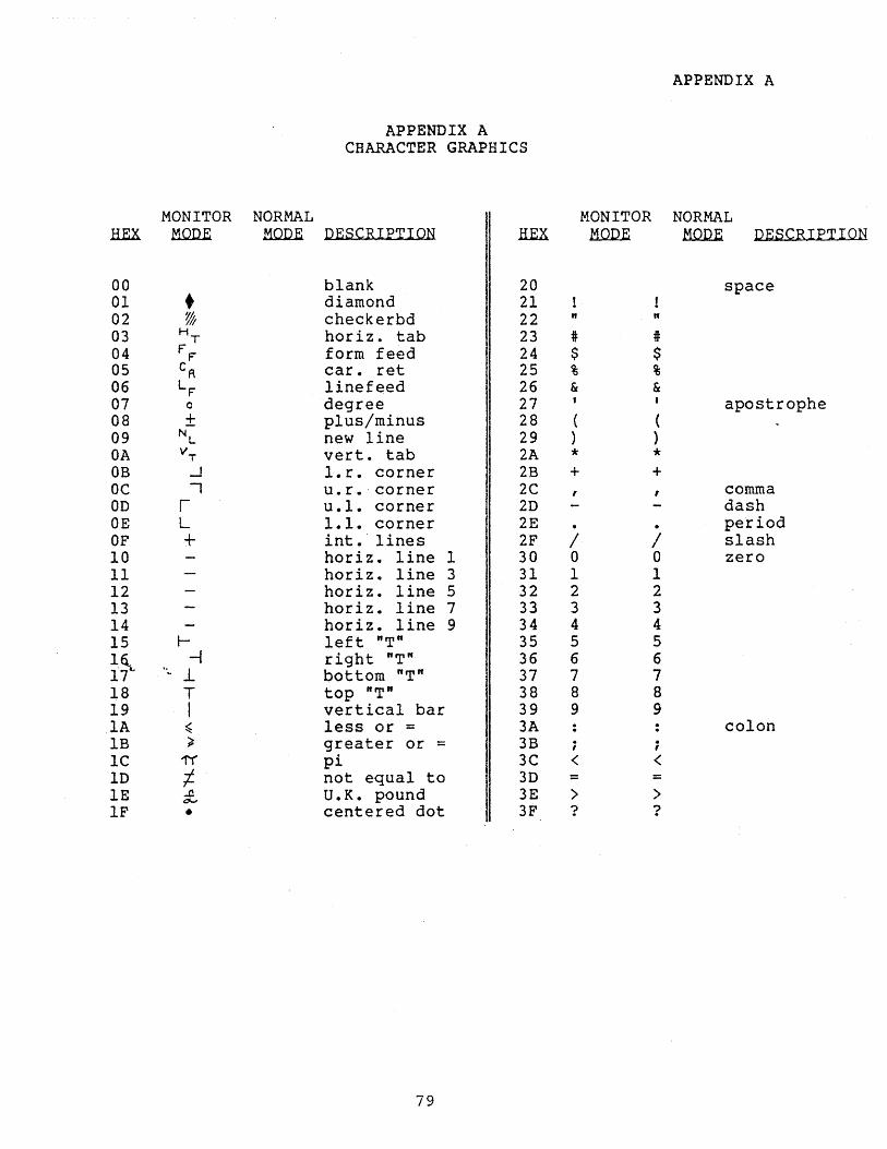
APPENDIX ACHARACTER GRAPHICS
APPENDIX A
MONITOR NORMAL MONITOR NORMALH.EX MQl2E MQl2E DESCRIPTION HEX MQl2E MQl2E DESCRIPTION
00 blank 20 space01 • diamond 2102 % checkerbd 22 " "03 H
T horiz. tab 23 # i04 FF form feed 24 $ $05 cR car. ret 25 % %06 LF linefeed 26 & &07 0 degree 27 I apostrophe08 ± plus/minus 28 ( (09 NL new line 29 ) }OA vT vert. tab 2A * *OB -.J l.r. corner 2B + +OC "I u.r. corner 2C commaOD r u.l. corner 2D dashOE L 1.1. corner 2E . . periodOF + int.' lines 2F / / slash10 horiz. line 1 30 0 0 zero11 horiz. line 3 31 1 112 horiz. line 5 32 2 213 horiz. line 7 33 3 314 horiz. line 9 34 4 415 l- left "T" 35 5 51~ -1 right "T" 36 6 617l, .. 1. bottom "T" 37 7 718 T top "T" 38 8 819 I vertical bar 39 9 9lA ~ less or = 3A colonIB ) greater or = 3B i ;IC 1'( pi 3C < <lD 1- not equal to 3D = =IE £, U.K. pound 3E > >IF • centered dot 3F ? ?
79

APPENDIX A
APPENDIX ACHARACTER GRAPHICS
(continued)
MONITOR NORMAL MONITOR NORMALHEX MODE MODE DESCRIPTION HEX MQIlli .MQllli PESCRIPTI
40 @ @ 60 ... single que41 A A 61 a a42 B B 62 b b43 C C 63 c c44 D D 64 d d45 E E 65 e e46 F F 66 f f47 G G 67 9 948 H H 68 h h49 I I 69 i i4A J J 6A j j4B K K 6B k k4C L L 6C 1 14D M M 6D rn rn4E N N 6E ,n n4F 0 0 6F 0 0
50 P P 70 P P51 Q Q 71 q q52 It R 72 r r53'- S S 73 s s54 T T 74 t t55 U U 75 u u56 V V 76 v v57 W W 77 w w58 X X 78 x x59 y y 79 Y YSA Z Z 7A z z5B [ [ 7B { {5C \ \ 7C I I5D ] ] 7D } }5E
,. ,.7E -
SF underscore 7F % delete ch
80

APPENDIX B
APPENDIX BKEYS NOT AFFECTED BY KEYBOARD MODES
CONTROL CONTROLKEY UNSHIFTED SHIFTED UNSHIFTED SHIFTED
CAPTION ASCII 1rnX ASCII HEX ASCII ~ ASCII .H.EX
ESC ESC IB ESC IB ESC IB ESC IB!1 1 31 21 1 31 21@2 2 32 @ 40 NULL 00 NULL 00#3 3 33 # 23 # 23 i 23$4 4 34 $ 24 4 34 $ 24%5 5 35 % 25 5 35 % 25,.,
6 6 36 5E 6 36 RS IE&7 7 37 & 26 7 37 & 26*8 8 38 * 2A 8 38 * 2A(9 9 39 ( 28 9 39 ( 28)a 0 30 } 29 0 30 } 29
2D 5F US IF US IF+= = 3D + 2B = 3D + 2B... '\ 60 60 NUL 00 NUL 00BACKSPACE BS 08 BS 08 BS 08 BS 08
TAB HT 09 HT 09 HT 09 HT 09
Q q 71 Q 51 DCl 11 DCl 11
W w 77 W 57 ETB 17 ETB 17
E e 65 E 45 ENQ 05 ENQ 45
R r 72 R 52 DC2 12 DC2 12
T t 74 T 54 DC4 14 DC4 14
Y Y 79 Y 59 EM 19 EM 19
U u 75 U 55 NAK 15 NAK 15
I i 69 I 49 HT 09 HT 09
81
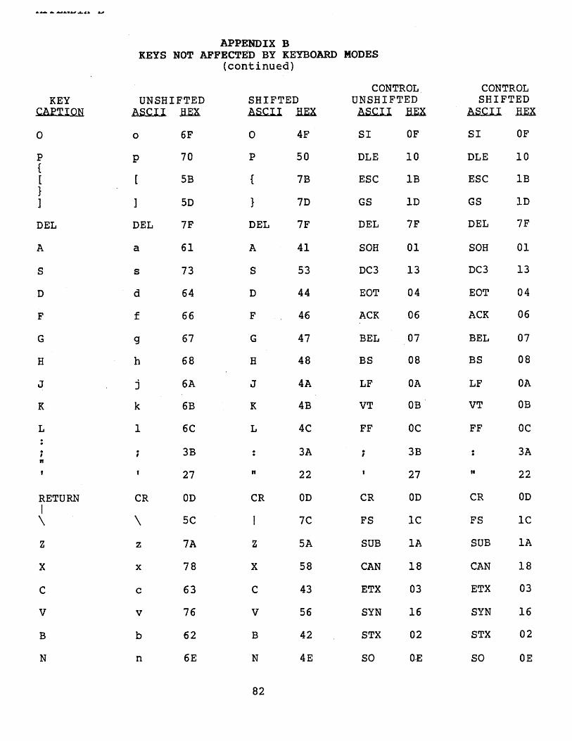
................, ..4& &J
APPENDIX BKEYS NOT AFFECTgn BY KEYBOARD MODES
(continued)
CONTROL CONTROLKEY UNSHIFTED SHIFTED UNSHIFTED SHIFTED
CAPTION ASCII .ImX. ASCII ~ ASCII .fin ASCII HEX
0 0 6F 0 4F SI OF SI OF
P P 70 P 50 DLE 10 DLE 10{[ 5B { 7B ESC IB ESC IB}] ] 5D } 7D GS ID GS ID
DEL DEL 7F DEL 7F DEL 7F DEL 7F
A a 61 A 41 SOH 01 SOH 01
S s 73 S 53 DC3 13 DC3 13
D d 64 D 44 EOT 04 EOT 04
F f 66 F 46 ACK 06 ACK 06
G 9 67 G 47 BEL 07 BEL 07
H h 68 H 48 BS 08 BS 08
J j 6A J 4A LF OA LF OA
K k 6B K 4B VT OB VT OB
L 1 6C L 4C FF OC FF OC
; ; 3B 3A . 3B . 3AI .n
27 n 22 27 " 22
RETURN CR OD CR OD CR OD CR ODI\ \ 5C 7C FS lC FS lC
Z z 7A Z 5A SUB lA SUB lA
X x 78 X 58 CAN 18 CAN 18
C c 63 C 43 ETX 03 ETX 03
V v 76 V 56 SYN 16 SYN 16
B b 62 B 42 STX 02 STX 02
N n 6E N 4E SO O-E SO OE
82
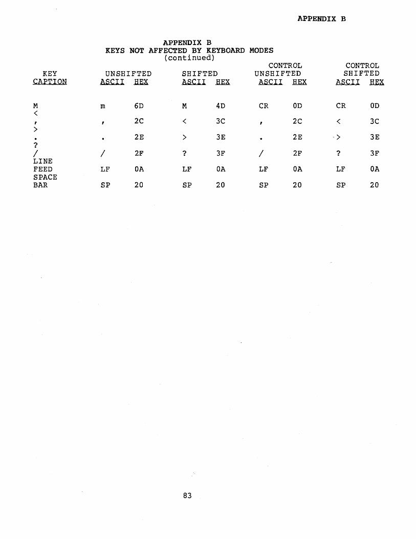
APPENDIX B
APPENDIX BKEYS NOT AFFECTED BY KEYBOARD MODES
(continued)CONTROL CONTROL
KEY UNSHIFTED SHIFTED UNSHIFTED SHIFTEDCAPTION ASCII HEX ASCII .HEX ASCII REX ASCII .HEX
M m 6D M 4D CR OD CR OD<, , 2C < 3C , 2C < 3C)
2E ) 3E 2E -) 3E?/ / 2F ? 3F / 2F ? 3FLINEFEED LF OA LF OA LF OA LF OASPACEBAR SP 20 SP 20 SP 20 SP 20
83
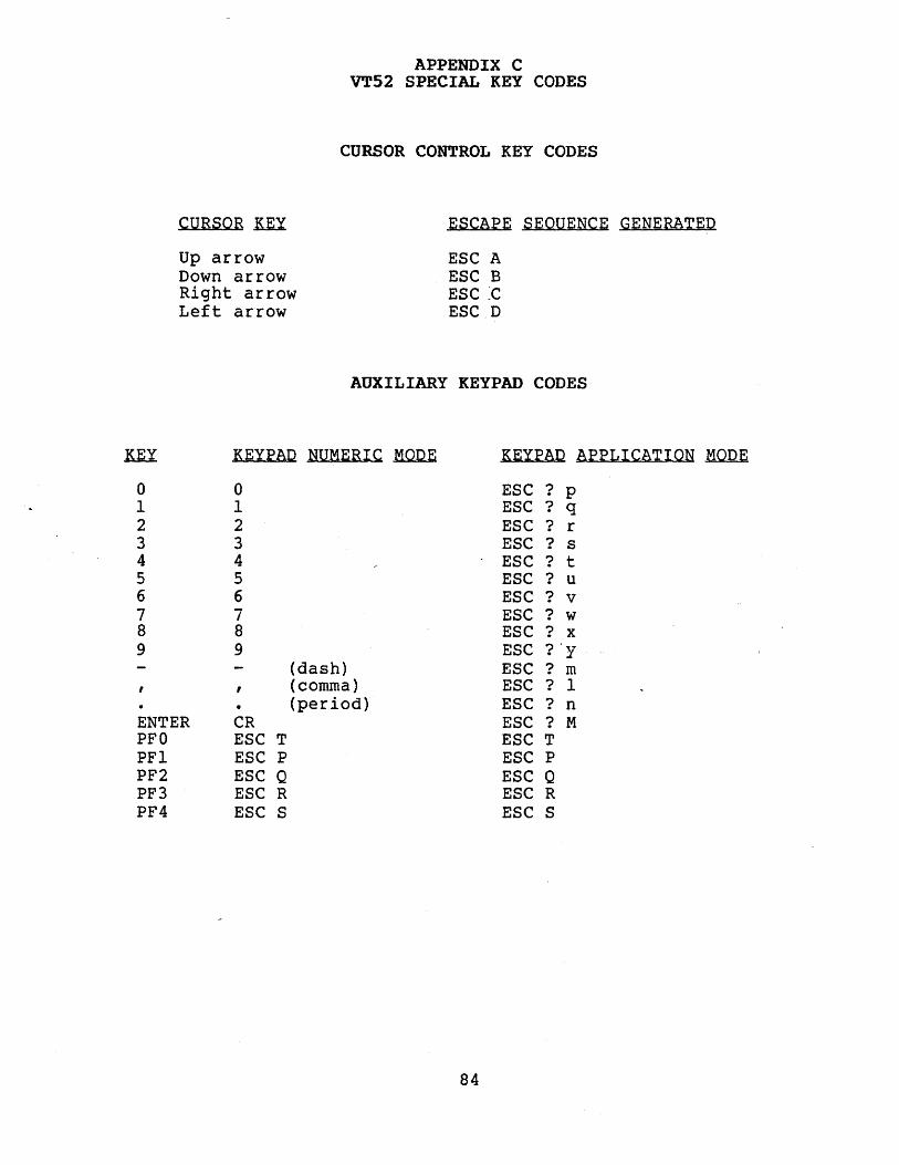
CURSOR .MX
Up arrowDown arrowRight arrowLeft arrow
APPENDIX CVT52 SPECIAL KEY CODES
CURSOR CONTROL KEY CODES
ESCAPE SEQUENCE GENERATED
ESC AESC BESC ~C
ESC D
AUXILIARY KEYPAD CODES
nx KEYPAD NUMERIC .M.QQ.E KEYPAD APPLICATION .M.QQ.E
a a ESC ? P1 1 ESC ? q2 2 ESC ? r3 3 ESC ? s4 4 ESC ? t5 5 ESC ? u6 6 ESC ? v7 7 ESC ? w8 8 ESC ? x9 9 ESC ?'y
(dash) ESC ? m, (comma) ESC ? 1• (period) ESC ? n
ENTER CR ESC ? MPFa ESC T ESC TPFI ESC P ESC PPF2 ESC Q ESC QPF3 ESC R ESC RPF4 ESC S ESC S
84
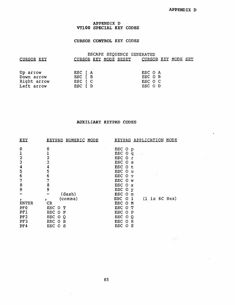
CURSOR .KEY
APPENDIX D
APPENDIX DVT100 SPECIAL KEY CODES
CURSOR CONTROL KEY CODES
ESCAPE SEQUENCE GENERATEDCURSOR ~~ RESET CURSOR ~~ SET
Up arrowDown arrowRight arrowLeft arrow
ESC [ AESC [ BESC [ CESC [ D
AUXILIARY KEYPAD CODES
ESC 0 AESC 0 BESC 0 CESC 0 D
KE.X: KEYPAD NUMERIC .MQD.E KEYPAD APPLICATION .MQD.E
0 0 ESC 0 P1 1 ESC 0 q2 2 ESC 0 r3 3 ESC 0 s4 4 ESC 0 t5 5 ESC 0 u6 6 ESC o v7 7 ESC o w8 8 ESC o x9 9 ESC o y
(dash) ESC o m, , (comma) ESC 0 1 (I is 6C Hex)ENTER CR ESC o MPFO ESC 0 T ESC o TPFI ESC 0 P ESC 0 PPF2 ESC 0 Q ESC o QPF3 ESC 0 R ESC 0 RPF4 ESC 0 S ESC 0 S
85
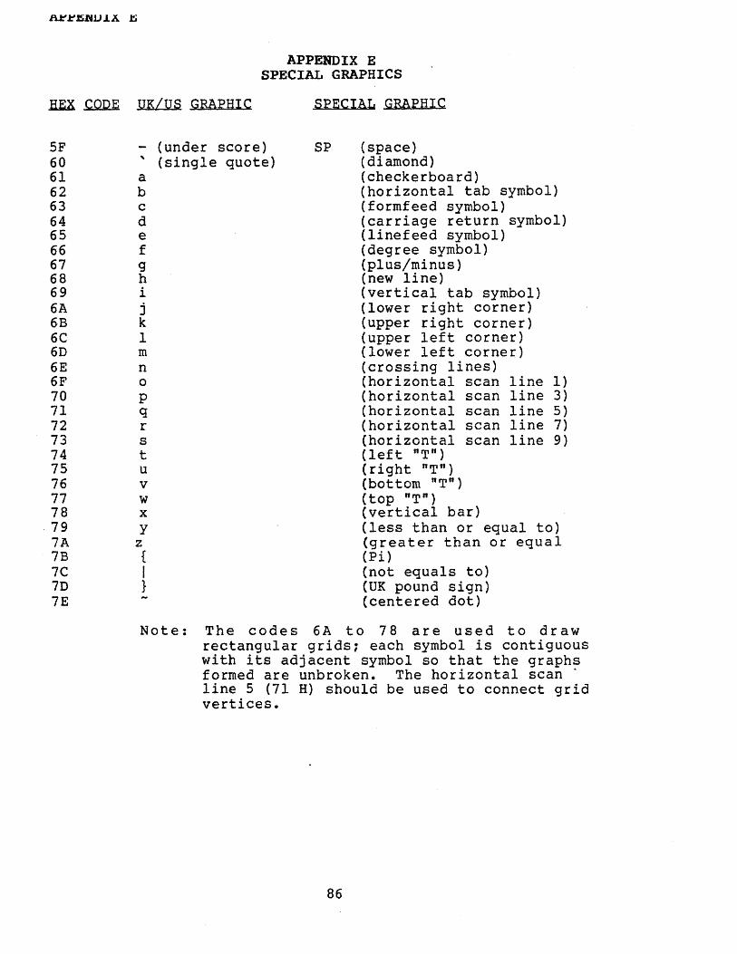
REA~ UK/US GRAPHIC
APPENDIX ESPECIAL GRAPHICS
SPECIAL GRAPHIC
SF606162636465666768696A6B6C6D6E6F707172737475767778797A7B7C7D7E
- (under score), (single quote)abcdefghijk1mnopqrstuvwxy
z{I}
SP (space)(diamond)(checkerboard)(horizontal tab symbol)(formfeed symbol)(carriage return symbol)(linefeed symbol)(degree symbol)(plus/minus)(new line)(vertical tab symbol)(lower right corner)(upper right corner)(upper left corner)(lower left corner)(crossing lines)(horizontal scan line 1)(horizontal scan line 3)(horizontal scan line 5)(horizontal scan line 7)(horizontal scan line 9)(left "T")(right "T")(bottom "T")(top "T")(vertical bar)(less than or equal to)(greater than or equal(Pi)(not equals to)(UK pound sign)(centered dot)
Note: The codes 6A to 78 are used to drawrectangular grids; each symbol is contiguouswith its adjacent symbol so that the graphsformed are unbroken. The horizontal scan .line 5 (71 H) should be used to connect gridvertices.
86
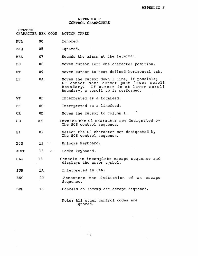
APPENDIX F
APPENDIX FCONTROL CHARACTERS
CONTROLCHARACTER HEX~ ACTION TAKEN
NUL
ENQ
BEL
BS
HT
LF
00
05
07
08
09
OA
Ignored.
Ignored.
Sounds the alarm at the terminal.
Moves cursor left one character position.
Moves cursor to next defined horizontal tab.
Moves the cursor down 1 line, if possible;LF cannot move cursor past lower scrollBoundary. If cursor is at lower scrollBoundary, a scroll up is performed.
VT DB
FF OC
CR 00
SO OE
SI OF
XON 11
XOFF 13
CAN 18
SUB lA
ESC lB
DEL 7F
Interpreted as a formfeed.
Interpreted as a linefeed.
Moves the cursor to column 1.
Invokes the Gl character set designated byThe SCS control sequence.
Select the GO character set designated byThe ses control sequence.
Unlocks key~oard.
Locks keyboard.
Cancels an incomplete escape sequence anddisplays the error symbol.
Interpreted as CAN.
Announces the ini tiation of an escapeSequence.
Cancels an incomplete escape sequence.
Note: All other control codes areIgnored.
87

nrrJ:l.nuJ.A U
APPENDIX GMODE OPTIONS
OPTIONS~~ MNEMONIC VALUE RESET
Insert/ IRMReplace
Vertical VEMEditing
New Line LNM
Cursor CURKYKey
VT100/ ANSIFVT52
Slow SLWSCRL·Scroll
Origin ORIGIN
Autowrap AUTOWRP
4 *Inserts characterat active position
7 *Edit movementAbove activeLine.
20 Follow receivedlinefeeds withCR; insert keyboard generatedcarriage returnswith a linefeed.
?l Cursor keys sendsequence denotedin the right column of AppendixD.
?2 Places terminalin the VT100mode.
?4 Places terminalin slow/smoothscroll mode.
?6 Origin is withrespect to thescroll region.
?7 Autowrap thecharacter tothe next linewhenever a character is sent thesecond time tothe last screenposition.
Replaces characterat active position.
Edit movementBelow activeLine.
Do not insertadditional charactersinto received linefeedsor keyboard generatedcarriage returns.
Cursor keys sendsequence denotedin the left column of AppendixD.
Places terminalin the VT52mode.
Places terminalin jump scrollmode.
Origin is withrespect to thepartition region.
Do not autowrap.
Monitor MONIT ?90 *Set monitor modeto display control characters.
88
Do-not set monitor mode.

APPENDIX G
APPENDIX GMODE OPTIONS
(continued)
OPTIONS~~ MNEMONIC VALUE RESET
SpecialErasureEdit
EDIT ?91 *When both ORIGINand this mode areset, erase withrespect to scrollboundaries.
Always erase withrespect to thepartition boundaries.
Note: The * indicates that the indicated mode is not includedin the DEC's VT100 command repertoire.
89

Primary Rendition
Bold
Underline
Slow blink
Reverse Video
Overstrike
APPENDIX HGRAPHIC RENDITIONS
PARAMETER VALUE IS~ COMMAND
o
1
4
5
7
99 Not available inthe DEC repertoire.
90
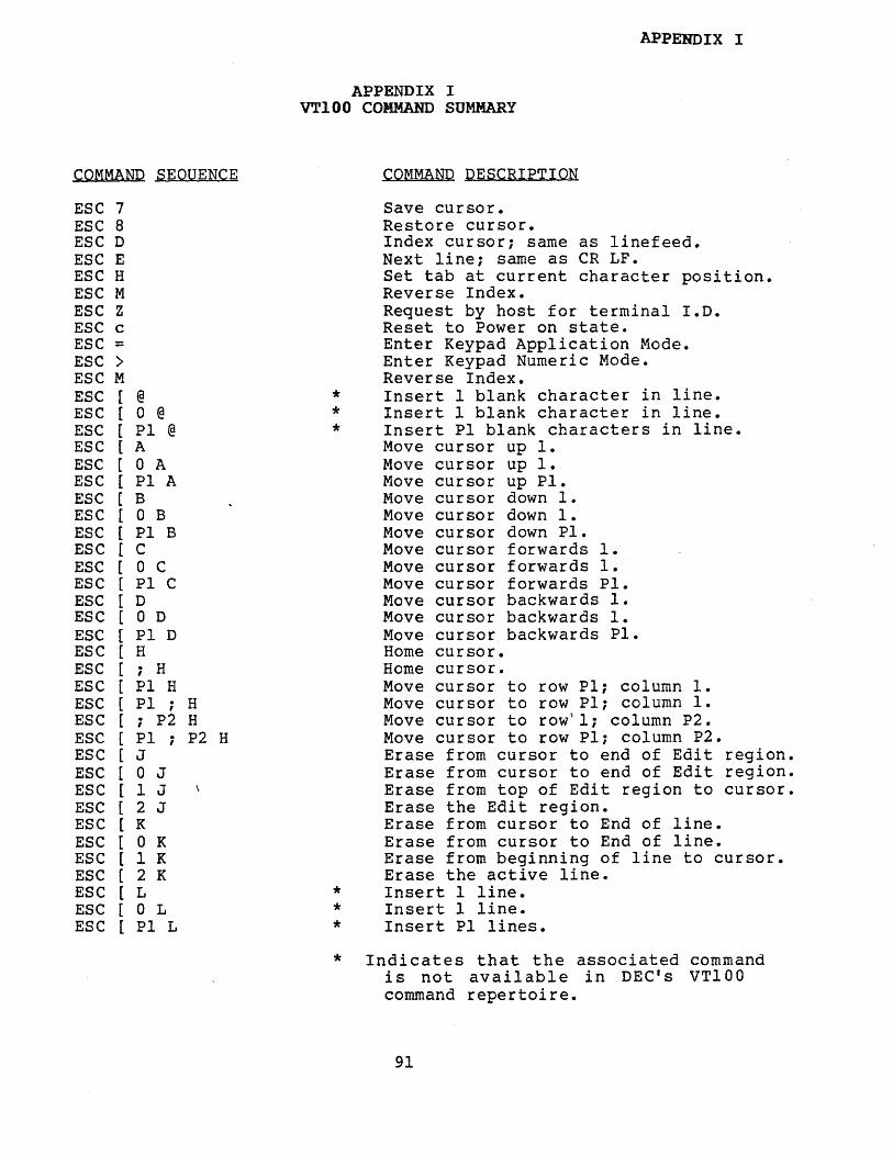
APPENDIX IVT100 COMMAND SUMMARY
APPENDIX I
COMMAND SEQUENCE COMMAND DESCRIPTION
ESC 7 Save cursor.ESC 8 Restore cursor.ESC D Index cursor; same as linefeed.ESC E Next line; same as CR LF.ESC H Set tab at current character position.ESC M Reverse Index.ESC Z Request by host for terminal I.D.ESC c Reset to Power on state.ESC = Enter Keypad Application Mode.ESC > Enter Keypad Numeric Mode.ESC M Reverse Index.ESC [ @ * Insert 1 blank character in line.ESC [ 0 @ * Insert 1 blank character in line.ESC [ PI @ * Insert PI blank characters in line.ESC [ A Move cursor up 1.ESC [ 0 A Move cursor up 1.ESC [ PI A Move cursor up Pl.ESC [ B ftllove cursor down 1.ESC [ 0 B Move cursor down 1.ESC [ PI B Move cursor down Pl.ESC [ C Move cursor forwards 1.ESC [ 0 e Move cursor forwards 1.ESC [ PI C Move cursor forwards Pl.ESC [ D Move cursor backwards 1.ESC [ 0 D Move cursor backwards 1.ESC [ PI D Move cursor backwards Pl.ESC [ H Home cursor.ESC [ i H Home cursor.ESC [ PI H Move cursor to row PI: column 1.ESC [ PI . H Move cursor to row PI; column 1.I
ESC [ ; P2 H Move cursor to row)l: column P2.ESC [ PI ; P2 H Move cursor to row PI; column P2.ESC [ J Erase from cursor to end of Edit region.ESC [ 0 J Erase from cursor to end of Edit region.ESC [ 1 J Erase from top of Edit region to cursor.ESC [ 2 J Erase the Edit region.ESC [ K Erase from cursor to End of line.ESC [ 0 K Erase from cursor to End of line.ESC [ 1 K Erase from beginning of line to cursor.ESC [ 2 K Erase the active line.ESC [ L * Insert 1 line.ESC [ 0 L * Insert 1 line.ESC [ PI L * Insert PI lines.
* Indicates that the associated commandis not available in DEC's VT100command repertoire.
91
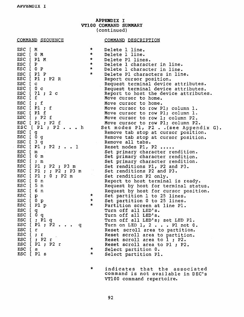
~.l-'~l'4DIX I
APPElIDIX IVT100 COMMAND SUMMARY
(continued)
COMMAND SEQUENCE
ESC [ M *ESC [ 0 M *ESC [ PI M *ESC [ P *ESC [ 0 P *ESC [ PI P *ESC [ PI ; P2 RESC [ cESC [ 0 cESC [ 11 ; 2 cESC [ fESC [ ; fESC [ PI ; fESC [ PI fESC [ ; P2 fESC [ PI ; P2 fESC [ PI ; P2 ••• hESC [ 9ESC [ 0 9ESC [ 3 9ESC [ PI ; P2 i • • 1ESC [ mESC [ 0 mESC [ ; mESC [ PI ; P2 ; P3 mESC [ PI ; ; P2 ; P3 mESC [ PI ; 0 ; P2 rnESC [ 0 nESC [ 5 nESC [ 6 nESC [ P *ESC [ 0 p *ESC [ PI P *ESC [ qESC [ 0 qESC [ i PI qESC [ PI ; P2 • qESC [ rESC [ ; rESC [ ; P2 rESC [ PI ; P2 rESC [ 5 *ESC [ PI s *
COMMAND DESCRIPTION
Delete 1 line.Delete 1 line.Delete PI lines.Delete 1 character in line.Delete 1 character in line.Delete PI characters in line.Report cursor position.Request terminal device attributes.Request terminal device attributes.Report to host the device attributes.Move cursor to home.Move cursor to home.Move cursor to row PI; column 1.Move cursor to row PI; column 1.Move cursor to row 1; column P2.Move cursor to row PI; column P2.
Set modes PI, P2 •• (see Appendix G).Remove tab stop at cursor position.Remove tab stop at cursor position.Remove all tabs.Reset modes PI, P2 •••••Set primary character rendition.Set primary character rendition.Set primary character rendition.Set renditions PI, P2 and P3.Set renditions P2 and P3.Set rendition P2 only.Report to host terminal is ready.Request by host for terminal status.Request by host for cursor position.Set partition I to 25 lines.Set partition 0 to 25 lines.Partition screen at line Pl.Turn off all LED'S.Turn off all LED's.Turn off all LED's; set LED Pl.Turn on LED I, 2 ••• PI not O.Reset scroll area to partition.Reset scroll area to partition.Reset scroll area to 1 ; P2.Reset scroll area to PI ; P2.Select partition O.Select partition Pl.
* indicates that the associatedcommand is not available in DEC'sVT100 command repertoire.
92

COMMAND SEQUENCE
ESC i 3ESC i 4ESC # 5ESC # 6ESC # 8ESC ( AESC ( BESC ( 0ESC ( 1ESC ( 2ESC ) AESC ) BESC ) 0ESC ) 1ESC ) 2
APPENDIX I
APPENDIX IVT100 COMMAND SUMMARY
(continued)
COMMAND DESCRIPTION
Set top half of double height/width line.Set bottom half of double height/width line.Set normal height/width line.Set double width line.Set screen to alignment pattarn.Set GO set UK character set.Set GO set ASCII character set.Set GO set special graphics set.Set GO set Alternate character set.Set GO set alternate special graphics set.Set GI set UK character set.Set GI set ASCII character set.Set Gl set special graphics set.Set GI set alternate character set.Set GI set alternate special graphics set.
93
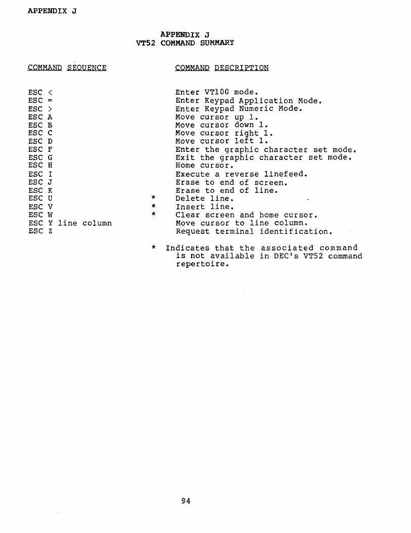
APPENDIX J
COMMAND SEOUENCE
APPENDIX JVT52 COMMAND SUMMARY
COMMAND PESCRIPTION
ESC <ESC =ESC >ESC AESC BESC CESC DESC FESC GESC HESC IESC JESC KESC UESC VESC WESC Y line columnESC Z
***
Enter VT100 mode.Enter Keypad Application Mode.Enter Keypad Numeric Mode.Move cursor up 1.Move cursor down 1.Move cursor right 1.Move cursor left 1.Enter the graphic character set mode.Exit the graphic character set mode.Home cursor.Execute a reverse linefeed.Erase to end of screen.Erase to end of line.Delete line.Insert line.Clear screen and home cursor.Move cursor to line column.Request terminal identification.
* Indicates that the associated commandis not available in DEC's VT52 commandrepertoire.
94

APPENDIX K
APPENDIX KREAR PANEL DIP SWITCH SETTINGS
SWl - UPPER SWITCH BANK
SWITCHNUMBER
1-8
1-71-61-51-41-31-21-1
SWITCH.HAME
Autowrap
XON/XOFFNew line modeMargin BellANSI/VT52 modeCursor BlinkCursor typeScreen mode
OFF POSITION(LEFT)
AutowrapEnabledDisabledEnabledEnabledVT52 modeSteady CursorDash CursorReverse Video
ON POSITION(RIGHT)
AutowrapDisabledEnabaledDisabledDisabledANSI modeBlinking CursorBlock CursorNormal Video
SW2 - LOWER SWITCH BANK
2-82-72-62-52-42-32-22-1
Local/OnlineData lengthParityparityBaud rate selectn
"n
Local/Test mode7 data bitsEven parityProcess parity
code
Online8 data bitsOdd parityIgnore parity
BAUD RATE SELECT CODE4 3 2 1 SW2
(N=ON; F=OFF)
N N N NN N N FN N N FN N F FN F N NN F N FN F F NN F F FF N N NF N N FF N F NF N F FF F N NF F N FF F F N
9600 BAUD7200480036002400200018001200
600300150134.5110
7550
95
(2 stop bits)(2 stop bits)(2 stop bits)

NO POSTAGENECESSARVIF lo4All.ED
IN THEUNITED STATES
IIIIIIIIIIIIII
• IIIIIIIIIII
BUSINESS REPLY MAILFirst Class Permit No. 130 ' 'vVestiake Village. CA
Postage will be paid by addressee
~ DATA SYSTEMS
2637 Townsgate RoadWestlake Village. CA 91361
---------------------------------------~FOld
Note: Staples can cau.. problems with automated mall sorting equipment.Please use presaure sensitive or other gummed tape to seal this form.
CD100-- USERS' GUIDE
READER COMMENT FORM
If you desire a reply, please includ,e your name and address.
This form is used to communicate your views about this publication. They will besent to the author's department for review and aC,tion.
Possible topics for discussion are: clarity, accuracy, completeness, organization,usefulness and legibility.
Callen Data Systems reserves the right to use or distribute any of the informationy.ou supply without incurring any obligation whatever.
i------------~---~-----------------------I FOld
IIIIIIIIIIIIIIIIIIIIIII:IIIIIIIII'

READER COMMENT FORM
CD100 - -USERS' GUIDE
...~"
oS~
<;z~
§...",
o,..~


COmDATA SYSTEMS2637 Townsgale RoadWestlake Village. CA 91361(805) 497·6837