Dragster - das4vxwadkuqo.cloudfront.net · NE MATTER, DRAGSTER, 11070 VERSION 2.0, 2016 NE MATTER,...
15
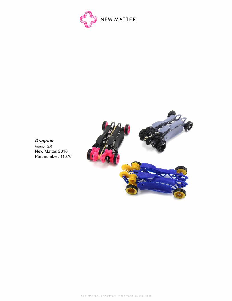
NEW MATTER, DRAGSTER, 11070 VERSION 2.0, 2016 Dragster Version 2.0 New Matter, 2016 Part number: 11070
Transcript of Dragster - das4vxwadkuqo.cloudfront.net · NE MATTER, DRAGSTER, 11070 VERSION 2.0, 2016 NE MATTER,...
N E W M A T T E R , D R A G S T E R , 1 1 0 7 0 V E R S I O N 2 . 0 , 2 0 1 6 N E W M A T T E R , D R A G S T E R , 1 1 0 7 0 V E R S I O N 2 . 0 , 2 0 1 6
DragsterVersion 2.0New Matter, 2016Part number: 11070
N E W M A T T E R , D R A G S T E R , 1 1 0 7 0 V E R S I O N 2 . 0 , 2 0 1 6
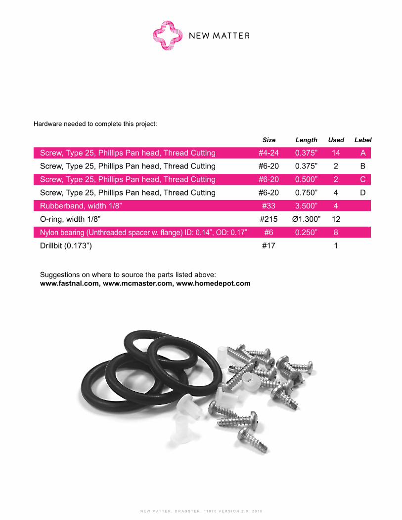
Hardware needed to complete this project:
Size Length Used Label
Screw, Type 25, Phillips Pan head, Thread Cutting #4-24 0.375” 14 A
Screw, Type 25, Phillips Pan head, Thread Cutting #6-20 0.375” 2 B
Screw, Type 25, Phillips Pan head, Thread Cutting #6-20 0.500” 2 C
Screw, Type 25, Phillips Pan head, Thread Cutting #6-20 0.750” 4 D
Rubberband, width 1/8” #33 3.500” 4
O-ring, width 1/8” #215 Ø1.300” 12
Nylon bearing (Unthreaded spacer w. flange) ID: 0.14”, OD: 0.17” #6 0.250” 8
Drillbit (0.173”) #17 1
Suggestions on where to source the parts listed above: www.fastnal.com, www.mcmaster.com, www.homedepot.com
N E W M A T T E R , D R A G S T E R , 1 1 0 7 0 V E R S I O N 2 . 0 , 2 0 1 6 N E W M A T T E R , D R A G S T E R , 1 1 0 7 0 V E R S I O N 2 . 0 , 2 0 1 6
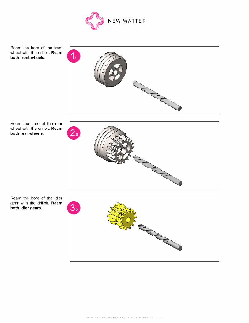
Ream the bore of the front wheel with the drillbit. Ream both front wheels.
Ream the bore of the rear wheel with the drillbit. Ream both rear wheels.
Ream the bore of the idler gear with the drillbit. Ream both idler gears.
1.0
2.0
3.0
N E W M A T T E R , D R A G S T E R , 1 1 0 7 0 V E R S I O N 2 . 0 , 2 0 1 6
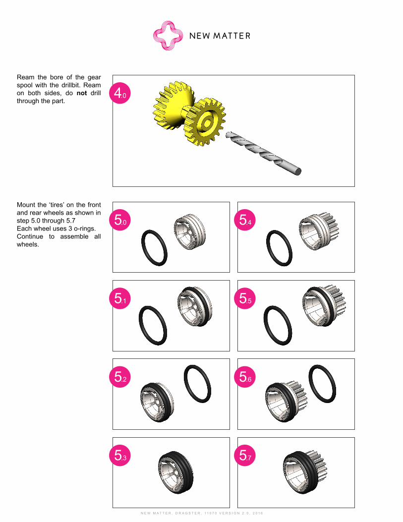
Ream the bore of the gear spool with the drillbit. Ream on both sides, do not drill through the part.
Mount the ‘tires’ on the front and rear wheels as shown in step 5.0 through 5.7Each wheel uses 3 o-rings.Continue to assemble all wheels.
4.0
5.0 5.4
5.1 5.5
5.2 5.6
5.3 5.7
N E W M A T T E R , D R A G S T E R , 1 1 0 7 0 V E R S I O N 2 . 0 , 2 0 1 6 N E W M A T T E R , D R A G S T E R , 1 1 0 7 0 V E R S I O N 2 . 0 , 2 0 1 6
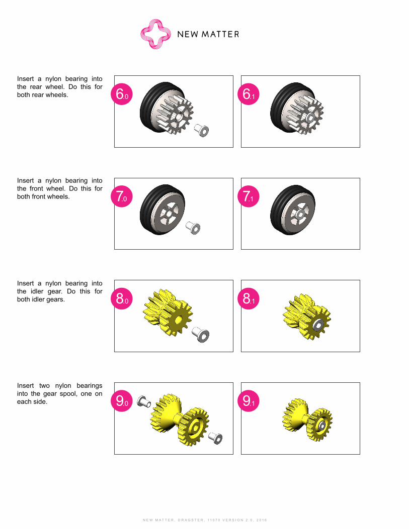
Insert a nylon bearing into the rear wheel. Do this for both rear wheels.
Insert a nylon bearing into the front wheel. Do this for both front wheels.
Insert a nylon bearing into the idler gear. Do this for both idler gears.
Insert two nylon bearings into the gear spool, one on each side.
6.0
7.0
8.0
9.0
6.1
7.1
8.1
9.1
N E W M A T T E R , D R A G S T E R , 1 1 0 7 0 V E R S I O N 2 . 0 , 2 0 1 6
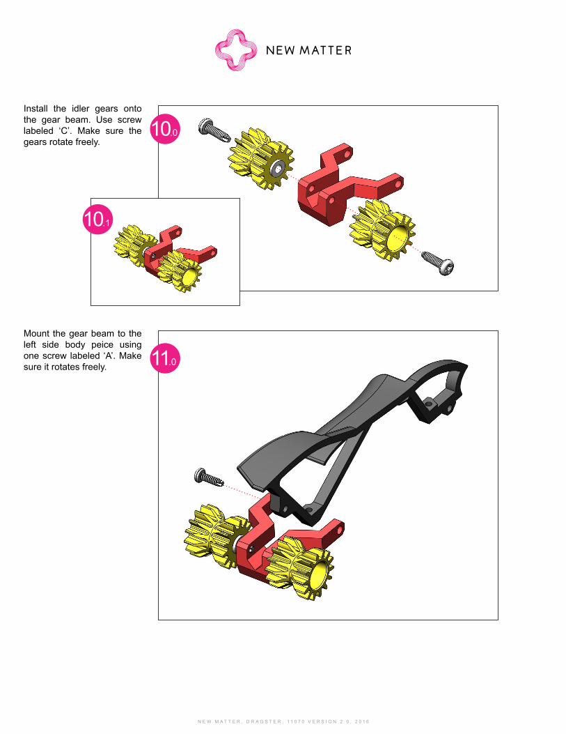
Install the idler gears onto the gear beam. Use screw labeled ‘C’. Make sure the gears rotate freely.
Mount the gear beam to the left side body peice using one screw labeled ‘A’. Make sure it rotates freely.
10.0
11.0
10.1
N E W M A T T E R , D R A G S T E R , 1 1 0 7 0 V E R S I O N 2 . 0 , 2 0 1 6 N E W M A T T E R , D R A G S T E R , 1 1 0 7 0 V E R S I O N 2 . 0 , 2 0 1 6
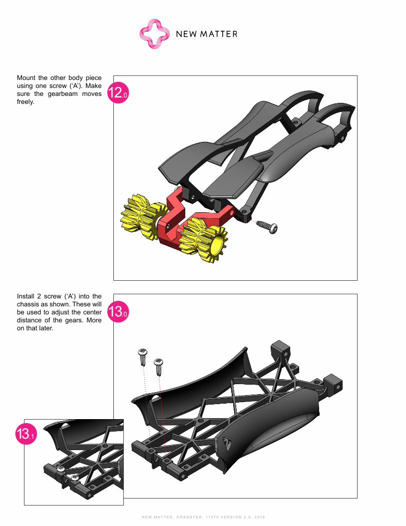
Mount the other body piece using one screw (‘A’). Make sure the gearbeam moves freely.
Install 2 screw (‘A’) into the chassis as shown. These will be used to adjust the center distance of the gears. More on that later.
12.0
13.0
13.1
N E W M A T T E R , D R A G S T E R , 1 1 0 7 0 V E R S I O N 2 . 0 , 2 0 1 6
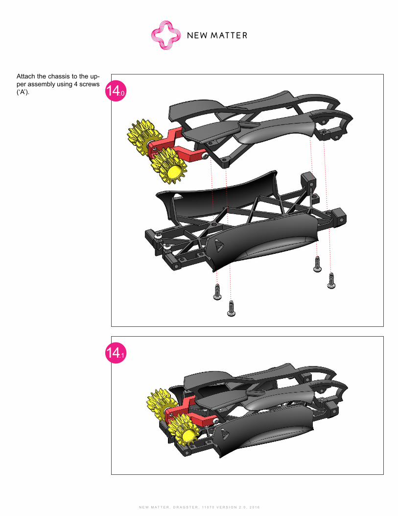
Attach the chassis to the up-per assembly using 4 screws (‘A’). 14.0
14.1
N E W M A T T E R , D R A G S T E R , 1 1 0 7 0 V E R S I O N 2 . 0 , 2 0 1 6 N E W M A T T E R , D R A G S T E R , 1 1 0 7 0 V E R S I O N 2 . 0 , 2 0 1 6
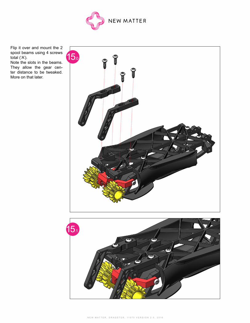
Flip it over and mount the 2 spool beams using 4 screws total (‘A’). Note the slots in the beams. They allow the gear cen-ter distance to be tweaked. More on that later.
15.0
15.1
N E W M A T T E R , D R A G S T E R , 1 1 0 7 0 V E R S I O N 2 . 0 , 2 0 1 6
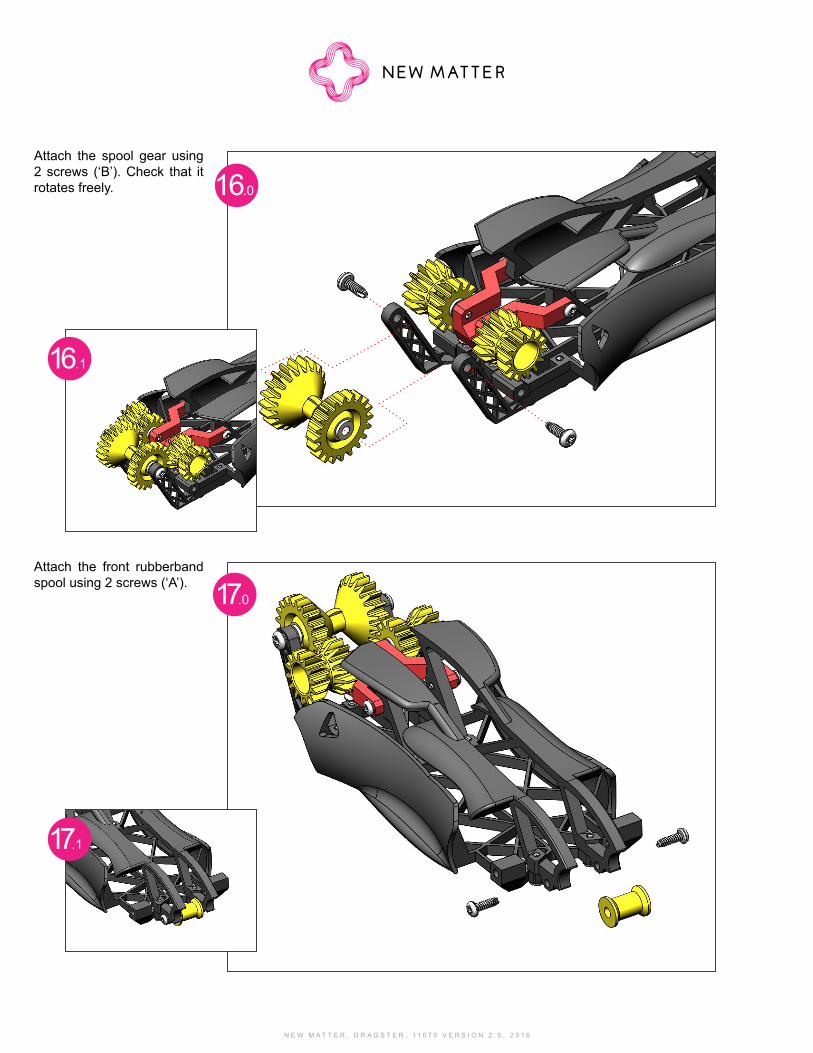
Attach the spool gear using 2 screws (‘B’). Check that it rotates freely. 16.0
Attach the front rubberband spool using 2 screws (‘A’). 17.0
16.1
17.1
N E W M A T T E R , D R A G S T E R , 1 1 0 7 0 V E R S I O N 2 . 0 , 2 0 1 6 N E W M A T T E R , D R A G S T E R , 1 1 0 7 0 V E R S I O N 2 . 0 , 2 0 1 6
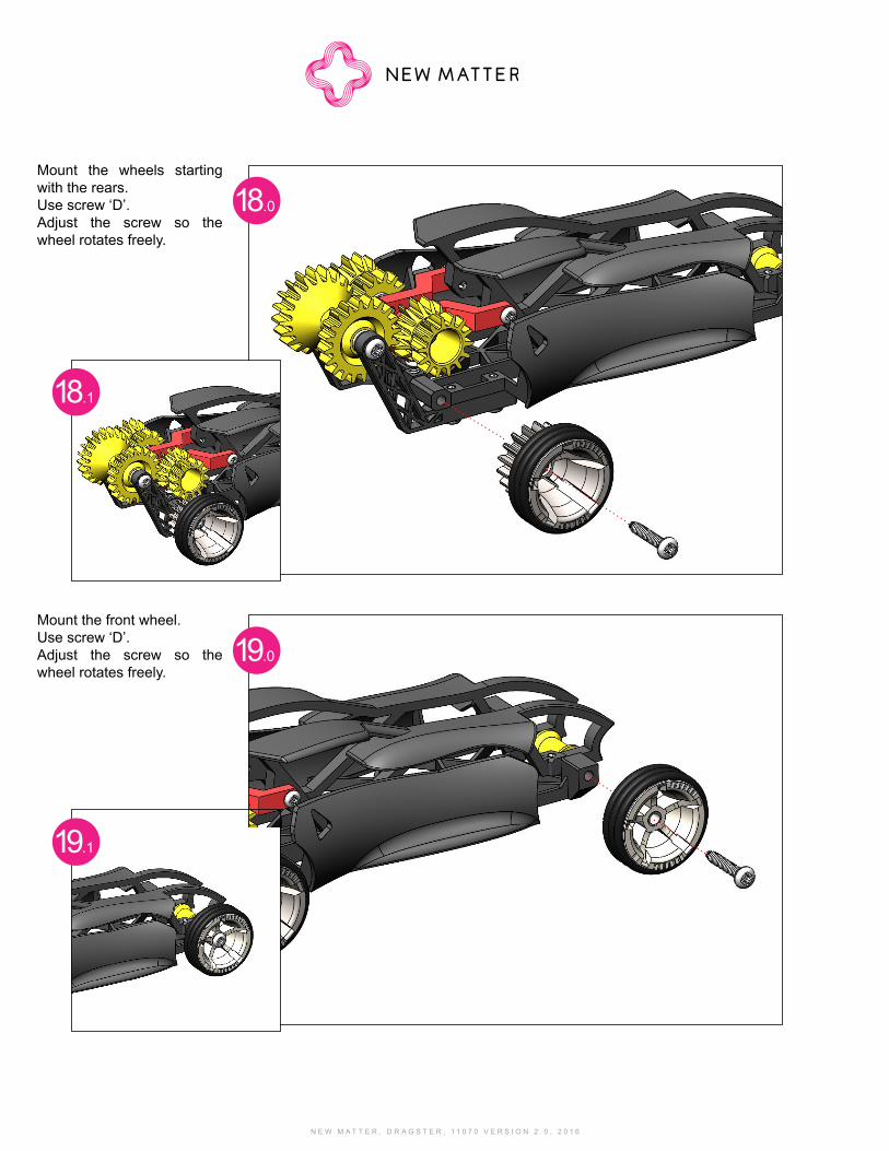
Mount the wheels starting with the rears.Use screw ‘D’. Adjust the screw so the wheel rotates freely.
Mount the front wheel.Use screw ‘D’. Adjust the screw so the wheel rotates freely.
18.0
19.0
18.1
19.1
N E W M A T T E R , D R A G S T E R , 1 1 0 7 0 V E R S I O N 2 . 0 , 2 0 1 6
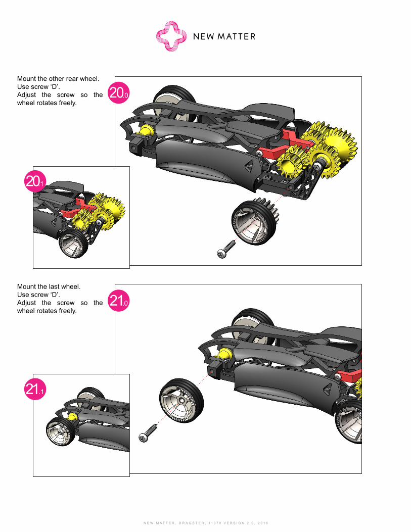
Mount the other rear wheel.Use screw ‘D’. Adjust the screw so the wheel rotates freely.
Mount the last wheel.Use screw ‘D’. Adjust the screw so the wheel rotates freely.
20.0
21.0
20.1
21.1
N E W M A T T E R , D R A G S T E R , 1 1 0 7 0 V E R S I O N 2 . 0 , 2 0 1 6 N E W M A T T E R , D R A G S T E R , 1 1 0 7 0 V E R S I O N 2 . 0 , 2 0 1 6
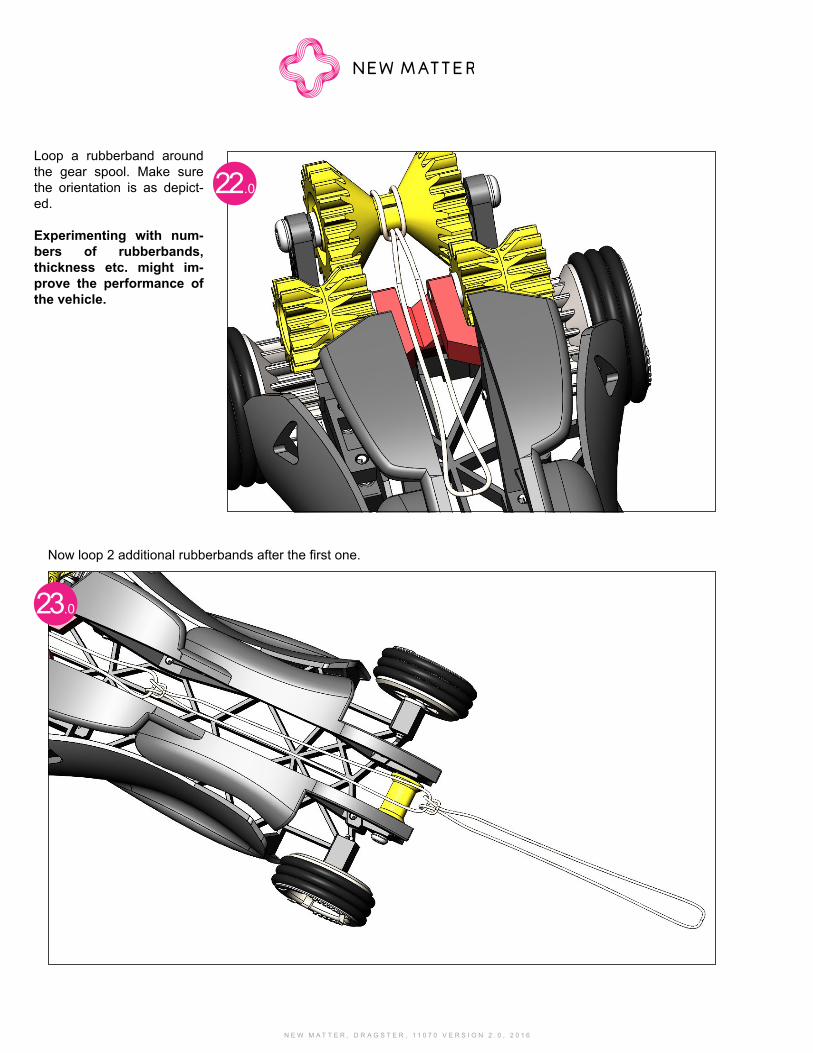
Loop a rubberband around the gear spool. Make sure the orientation is as depict-ed.
Experimenting with num-bers of rubberbands, thickness etc. might im-prove the performance of the vehicle.
Now loop 2 additional rubberbands after the first one.
22.0
23.0
N E W M A T T E R , D R A G S T E R , 1 1 0 7 0 V E R S I O N 2 . 0 , 2 0 1 6
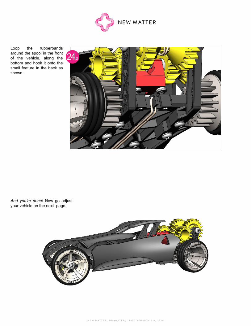
Loop the rubberbands around the spool in the front of the vehicle, along the bottom and hook it onto the small feature in the back as shown.
24.0
And you’re done! Now go adjust your vehicle on the next page.
N E W M A T T E R , D R A G S T E R , 1 1 0 7 0 V E R S I O N 2 . 0 , 2 0 1 6 N E W M A T T E R , D R A G S T E R , 1 1 0 7 0 V E R S I O N 2 . 0 , 2 0 1 6
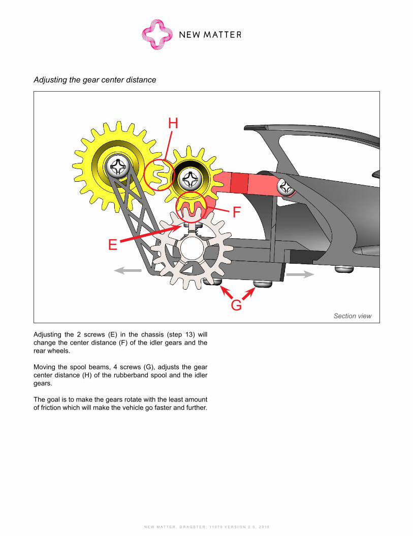
Adjusting the 2 screws (E) in the chassis (step 13) will change the center distance (F) of the idler gears and the rear wheels.
Moving the spool beams, 4 screws (G), adjusts the gear center distance (H) of the rubberband spool and the idler gears.
The goal is to make the gears rotate with the least amount of friction which will make the vehicle go faster and further.
Section view
Adjusting the gear center distance
E
H
F
G