DRAFT PROPOSAL FOR STORAGE CONNECTION …/media/files/Elia/users-group/WG Belgian...
14
DRAFT PROPOSAL FOR STORAGE CONNECTION REQUIREMENTS January 2018
Transcript of DRAFT PROPOSAL FOR STORAGE CONNECTION …/media/files/Elia/users-group/WG Belgian...
DRAFT PROPOSAL FOR STORAGE CONNECTION REQUIREMENTS
January 2018
Draft proposal for storage connection requirements – January 2018 Page 1 of 13
Contents
1 Introduction and background ...................................................... 2
2 Definitions and applicability ........................................................ 2
3 SPM categories types .................................................................. 3
4 SPM Type A.................................................................................. 4 4.1 Frequency stability & active power management .................................. 4
4.1.1 Frequency withstand capability ................................................ 4 4.1.2 Rate Of Change Of Frequency (ROCOF) withstand capability ....... 4 4.1.3 Limited Frequency Sensitive Mode (LFSM-O and LFSM-U) [Art. 13-2
(a) and Art. 15-2] ............................................................................. 4 4.1.4 Admissible maximum power reduction with falling frequency ...... 5 4.1.5 Logical interface to cease active power injection ........................ 5 4.1.6 Automatic connection ............................................................. 5 4.1.7 Rates of change of active power output .................................... 5
4.2 Information exchange ....................................................................... 6
5 SPM Type B .................................................................................. 7 5.1 Frequency stability and active power management ............................... 7
5.1.1 Remote control reduction of active power ................................. 7 5.1.1 Automatic reconnection .......................................................... 7
5.2 Information exchange ....................................................................... 7 5.2.1 Structural data ...................................................................... 7 5.2.2 Real-time measurements ........................................................ 8 5.2.3 Data to be received ............................................................... 8
5.3 Fault-ride through for symmetrical and asymmetrical faults ................... 8 5.4 Reactive capabilities - ....................................................................... 8 5.5 Fault Current & dynamic voltage support (optional) .............................. 9 5.6 Post-fault active power recovery (optional) .......................................... 9
6 SPM Type C ................................................................................ 10 6.1 Frequency stability& Active Power management .................................. 10
6.1.1 Active Power Controllability and Control Range ......................... 10 6.1.2 Limited frequency sensitive mode – under frequency (LFSM-U) .. 10 6.1.3 Frequency Sensitive Mode ..................................................... 10 6.1.4 Frequency restoration control ................................................. 10 6.1.5 Real-time monitoring of FSM .................................................. 11 6.1.1 Automatic disconnection for voltage outside ranges .................. 11
6.2 System restoration .......................................................................... 11 6.3 Reactive capabilities ......................................................................... 11 6.4 Voltage control ................................................................................ 12
7 SPM Type D ............................................................................... 12 7.1 Fault-ride through for symmetrical and asymmetrical faults .................. 12
8 References ................................................................................ 13
Draft proposal for storage connection requirements – January 2018 Page 2 of 13
1 Introduction and background
Electric storage systems are out of the scope of Connections Network Codes (CNCs) as referred in the Art 3-2 (d) in the RfG NC [1] and the Art 3-2 (b) in the DCC NC [2] with the
exception of pump-storage which is considered as a Power Generating Module (PGM).
Expected new storage capacities to be installed in Belgium would therefore require the development of adequate technical capabilities to close such gap with the aim to address system needs and to contribute to secure system operation. In this document we propose a set of minimum technical connection requirements for Storage Park Modules (SPM) as per the scope and the relevant terminologies and definitions used in the section 2 which cannot be considered as a part of the set of the general Requirements requested within the
CNCs. The proposed technical requirements are based on categories reflecting the significance and the expected capabilities of the storage system coherently with the ABCD limits defined for Power Generating Modules (PGM).
In general the possible technical capabilities of the SPM are similar to the ones of Power Park Modules (PPM) as they share similar technical aspects as modules connected to electricity networks through power electronics acting as inverter and rectifier for the case of SPM. Therefore, the proposed technical capabilities are aligned as much as possible with
the PPM’s exhaustive and non-exhaustive requirements defined in the RfG NC [1].
The main focus of this document is to specify the minimal technical requirements specifically applicable to storage systems taking into consideration specific intrinsic behavior of SPM, as well as the different operational modes as charging or discharging modes. Therefore, whenever no specific distinct provisions are required for SPM, the exhaustive and non-exhaustive requirements for PPM would be of application.
This document fixes the technical requirements that are subject to definition by the relevant TSO (Elia) and Elia as a Relevant System Operator. They are therefore applicable to the SPM connected to transmission network and whenever relevant to SPM connected to
DSO and/or CDSO networks in alignment with ENTSO-e guidance document for National Implementation of connection Network Codes [3].
2 Definitions and applicability
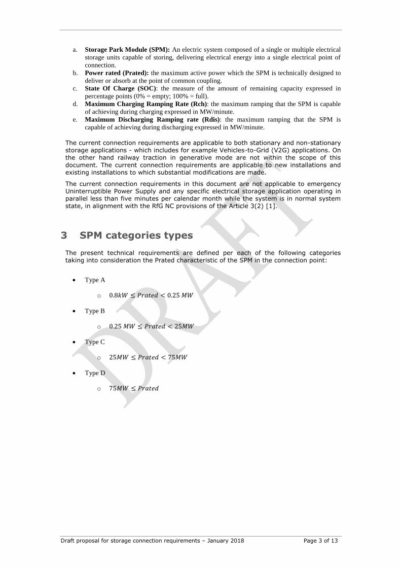
Figure 1 Example of Storage Park Module grid connection
Figure 1 illustrates possible grid connection of a SPM and the point of common coupling (also known as the connection point) to the transmission grid. This one could include
within the same facility other Power Generation Modules or demand units as auxiliary supply.
Below is a set of applicable definitions covering intrinsic capabilities of a SPM or relevant operational modes addressed within the current technical connection requirements:
Public Transmission
network
Gen=
~
POCC
=~
SPM
Central Control
Draft proposal for storage connection requirements – January 2018 Page 3 of 13
a. Storage Park Module (SPM): An electric system composed of a single or multiple electrical
storage units capable of storing, delivering electrical energy into a single electrical point of
connection.
b. Power rated (Prated): the maximum active power which the SPM is technically designed to
deliver or absorb at the point of common coupling.
c. State Of Charge (SOC): the measure of the amount of remaining capacity expressed in
percentage points (0% = empty; 100% = full).
d. Maximum Charging Ramping Rate (Rch): the maximum ramping that the SPM is capable
of achieving during charging expressed in MW/minute.
e. Maximum Discharging Ramping rate (Rdis): the maximum ramping that the SPM is
capable of achieving during discharging expressed in MW/minute.
The current connection requirements are applicable to both stationary and non-stationary storage applications - which includes for example Vehicles-to-Grid (V2G) applications. On
the other hand railway traction in generative mode are not within the scope of this
document. The current connection requirements are applicable to new installations and existing installations to which substantial modifications are made.
The current connection requirements in this document are not applicable to emergency Uninterruptible Power Supply and any specific electrical storage application operating in parallel less than five minutes per calendar month while the system is in normal system state, in alignment with the RfG NC provisions of the Article 3(2) [1].
3 SPM categories types
The present technical requirements are defined per each of the following categories taking into consideration the Prated characteristic of the SPM in the connection point:
Type A
o 0.8𝑘𝑊 ≤ 𝑃𝑟𝑎𝑡𝑒𝑑 < 0.25 𝑀𝑊
Type B
o 0.25 𝑀𝑊 ≤ 𝑃𝑟𝑎𝑡𝑒𝑑 < 25𝑀𝑊
Type C
o 25𝑀𝑊 ≤ 𝑃𝑟𝑎𝑡𝑒𝑑 < 75𝑀𝑊
Type D
o 75𝑀𝑊 ≤ 𝑃𝑟𝑎𝑡𝑒𝑑
Draft proposal for storage connection requirements – January 2018 Page 4 of 13
4 SPM Type A
4.1 Frequency stability & active power management
4.1.1 Frequency withstand capability
PGM type A exhaustive and non-exhaustive requirements on frequency withstand capability [see Art. 13-1 (a) RfG NC] are of application for the SPM type A.
4.1.2 Rate Of Change Of Frequency (ROCOF) withstand capability
PGM type A exhaustive and non-exhaustive requirements on Rate Of Change Of Frequency (ROCOF) withstand capability and Loss of Main Protection triggered by
rate-of-change-of-frequency-type [see Art 13.1(b) RfG NC] are of application for the SPM type A.
4.1.3 Limited Frequency Sensitive Mode (LFSM-O and LFSM-U)
[Art. 13-2 (a) and Art. 15-2]
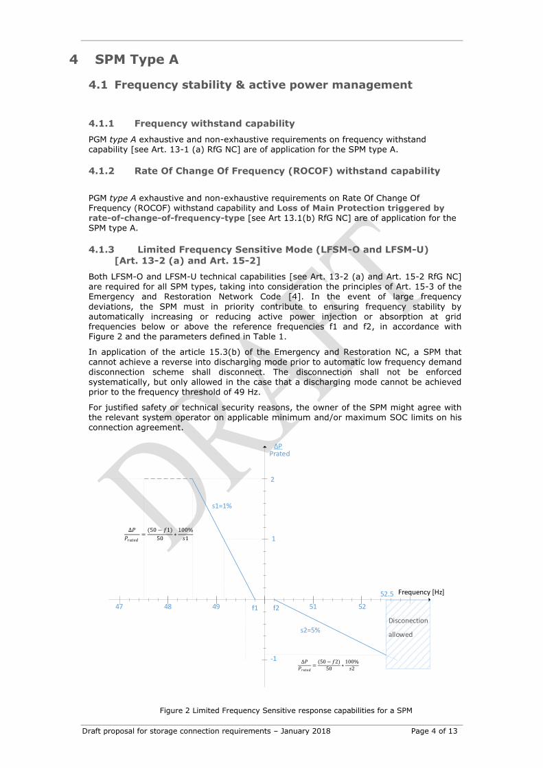
Both LFSM-O and LFSM-U technical capabilities [see Art. 13-2 (a) and Art. 15-2 RfG NC] are required for all SPM types, taking into consideration the principles of Art. 15-3 of the Emergency and Restoration Network Code [4]. In the event of large frequency
deviations, the SPM must in priority contribute to ensuring frequency stability by automatically increasing or reducing active power injection or absorption at grid frequencies below or above the reference frequencies f1 and f2, in accordance with Figure 2 and the parameters defined in Table 1.
In application of the article 15.3(b) of the Emergency and Restoration NC, a SPM that
cannot achieve a reverse into discharging mode prior to automatic low frequency demand
disconnection scheme shall disconnect. The disconnection shall not be enforced systematically, but only allowed in the case that a discharging mode cannot be achieved prior to the frequency threshold of 49 Hz.
For justified safety or technical security reasons, the owner of the SPM might agree with the relevant system operator on applicable minimum and/or maximum SOC limits on his connection agreement.
∆𝑃
𝑃𝑟𝑎𝑡𝑒𝑑=
(50 − 𝑓1)
50∗
100%
𝑠1
f2f1
Frequency [Hz]
51 52494847
1
-1
52.5
Disconection
allowed
PratedΔP
2
s1=1%
s2=5%
∆𝑃
𝑃𝑟𝑎𝑡𝑒𝑑=
(50 − 𝑓2)
50∗
100%
𝑠2
Figure 2 Limited Frequency Sensitive response capabilities for a SPM
Draft proposal for storage connection requirements – January 2018 Page 5 of 13
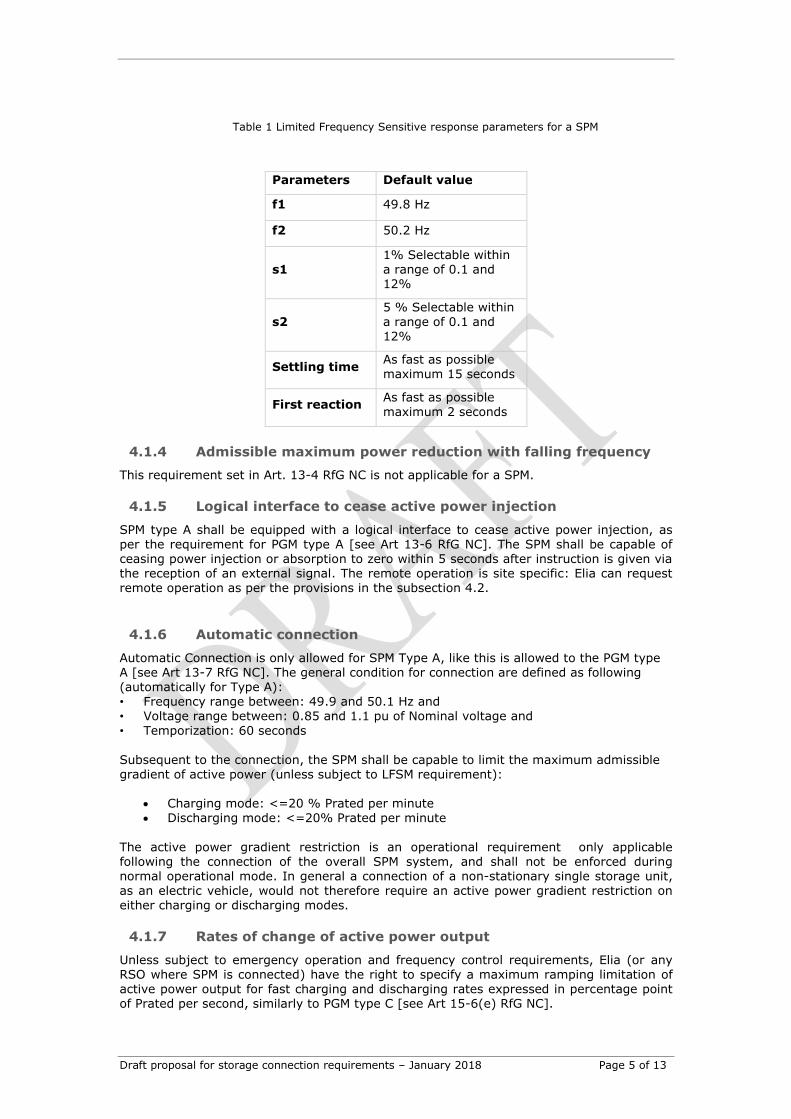
Table 1 Limited Frequency Sensitive response parameters for a SPM
Parameters Default value
f1 49.8 Hz
f2 50.2 Hz
s1 1% Selectable within a range of 0.1 and 12%
s2
5 % Selectable within
a range of 0.1 and 12%
Settling time As fast as possible maximum 15 seconds
First reaction As fast as possible maximum 2 seconds
4.1.4 Admissible maximum power reduction with falling frequency
This requirement set in Art. 13-4 RfG NC is not applicable for a SPM.
4.1.5 Logical interface to cease active power injection
SPM type A shall be equipped with a logical interface to cease active power injection, as per the requirement for PGM type A [see Art 13-6 RfG NC]. The SPM shall be capable of ceasing power injection or absorption to zero within 5 seconds after instruction is given via the reception of an external signal. The remote operation is site specific: Elia can request remote operation as per the provisions in the subsection 4.2.
4.1.6 Automatic connection
Automatic Connection is only allowed for SPM Type A, like this is allowed to the PGM type A [see Art 13-7 RfG NC]. The general condition for connection are defined as following (automatically for Type A): • Frequency range between: 49.9 and 50.1 Hz and • Voltage range between: 0.85 and 1.1 pu of Nominal voltage and
• Temporization: 60 seconds
Subsequent to the connection, the SPM shall be capable to limit the maximum admissible gradient of active power (unless subject to LFSM requirement):
Charging mode: <=20 % Prated per minute Discharging mode: <=20% Prated per minute
The active power gradient restriction is an operational requirement only applicable following the connection of the overall SPM system, and shall not be enforced during normal operational mode. In general a connection of a non-stationary single storage unit, as an electric vehicle, would not therefore require an active power gradient restriction on either charging or discharging modes.
4.1.7 Rates of change of active power output
Unless subject to emergency operation and frequency control requirements, Elia (or any RSO where SPM is connected) have the right to specify a maximum ramping limitation of active power output for fast charging and discharging rates expressed in percentage point of Prated per second, similarly to PGM type C [see Art 15-6(e) RfG NC].
Draft proposal for storage connection requirements – January 2018 Page 6 of 13
4.2 Information exchange
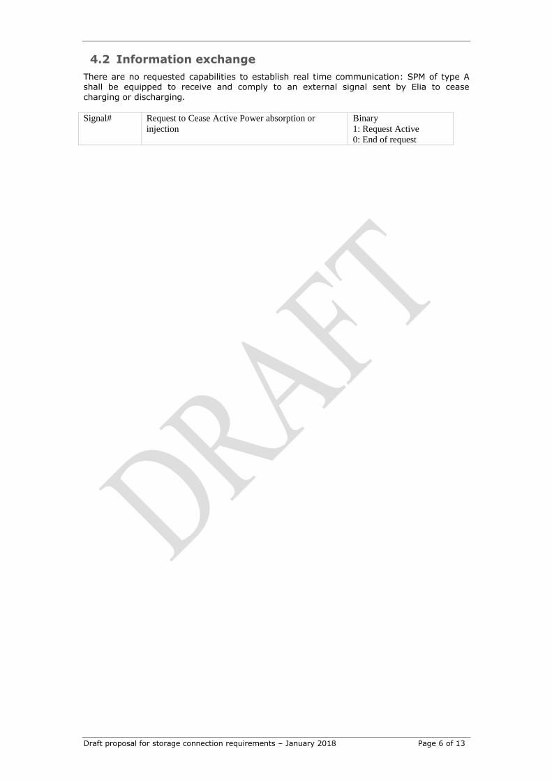
There are no requested capabilities to establish real time communication: SPM of type A shall be equipped to receive and comply to an external signal sent by Elia to cease charging or discharging.
Signal# Request to Cease Active Power absorption or
injection
Binary
1: Request Active
0: End of request
Draft proposal for storage connection requirements – January 2018 Page 7 of 13
5 SPM Type B
In addition to the specifications for SPM type A, the following is requested.
5.1 Frequency stability and active power management
5.1.1 Remote control reduction of active power
The SPM shall be capable, like the PGMs of type B [see Art 14 -2 RfG NC], of reducing its power
injection or absorption. The setpoint must be reached within a maximum duration of 1 minute and a
precision of 5% after instruction is given via the reception of an external signal.
Remote operation is site specific: Elia can request remote operation as per the provisions in subsection
5.2.3.
5.1.1 Automatic reconnection
For SPM units of Type B, C and D automatic reconnection is prohibited and subject to authorization in
their connection contracts, like the PGMs of Type B, C and D [see Art 14 -4 RfG NC].
The general condition for reconnection are defined as following:
• Frequency range between: 49.9 and 50.1 Hz and
• Voltage range between: 0.9 and 1.1 pu of Nominal voltage and
• Temporization: 60 seconds
A signal allowing the reconnection is foreseen in the sub-section 5.2.3. Subsequent to the reconnection
the SPM shall be capable to limit the admissible gradient of active power to the following (unless
subject to LFSM requirement):
Charging mode: 10 % Prated per minute
Discharging mode: 10% Prated per minute
5.2 Information exchange
Beside what is being requested for PGM in general in Art. 14-5 (d) RfG NC, the following is requested
for SPM:
5.2.1 Structural data
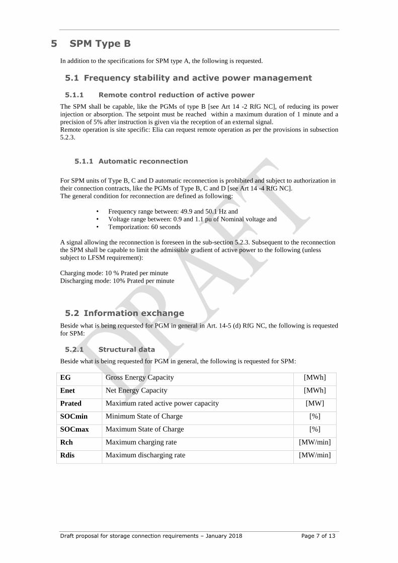
Beside what is being requested for PGM in general, the following is requested for SPM:
EG Gross Energy Capacity [MWh] Enet Net Energy Capacity [MWh] Prated Maximum rated active power capacity [MW] SOCmin Minimum State of Charge [%] SOCmax Maximum State of Charge [%] Rch Maximum charging rate [MW/min] Rdis Maximum discharging rate [MW/min]
Draft proposal for storage connection requirements – January 2018 Page 8 of 13
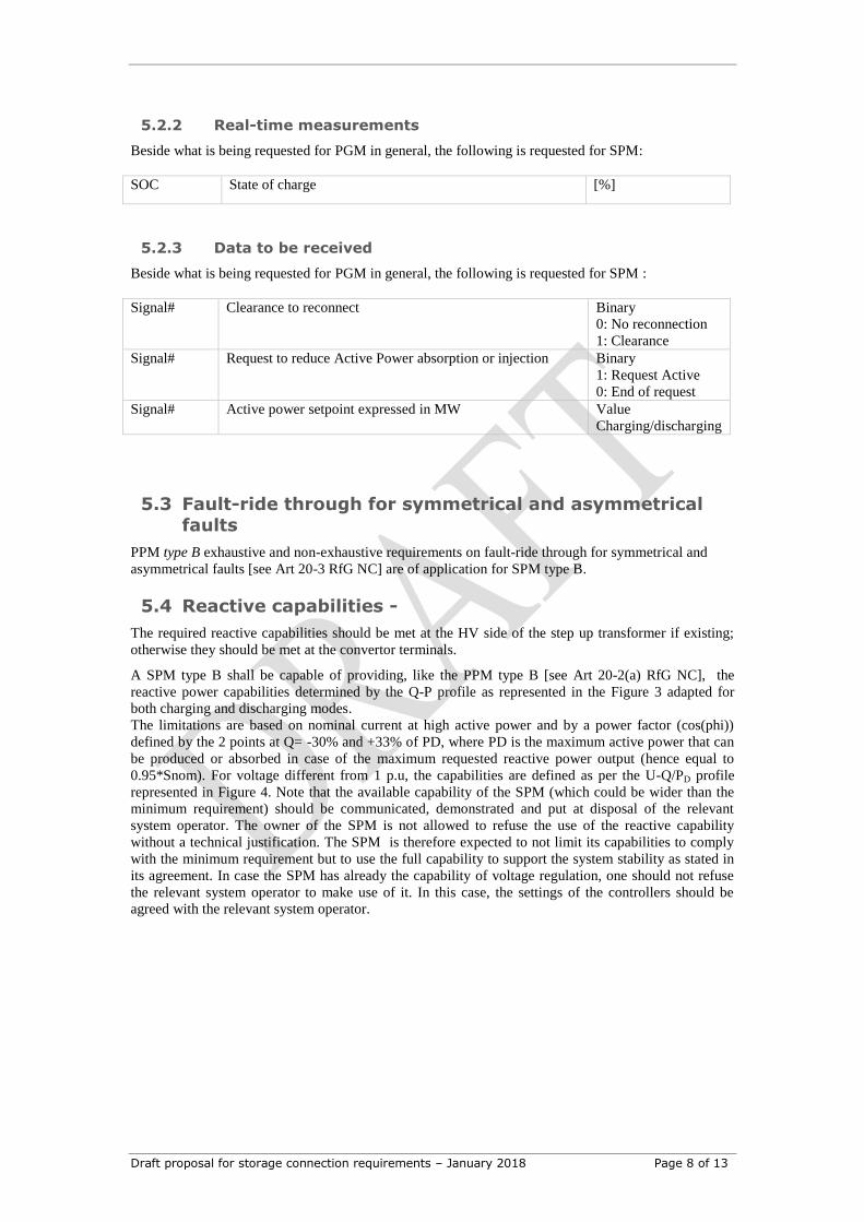
5.2.2 Real-time measurements
Beside what is being requested for PGM in general, the following is requested for SPM:
SOC State of charge [%]
5.2.3 Data to be received
Beside what is being requested for PGM in general, the following is requested for SPM :
Signal# Clearance to reconnect Binary
0: No reconnection
1: Clearance
Signal# Request to reduce Active Power absorption or injection Binary
1: Request Active
0: End of request
Signal# Active power setpoint expressed in MW
Value
Charging/discharging
5.3 Fault-ride through for symmetrical and asymmetrical faults
PPM type B exhaustive and non-exhaustive requirements on fault-ride through for symmetrical and
asymmetrical faults [see Art 20-3 RfG NC] are of application for SPM type B.
5.4 Reactive capabilities -
The required reactive capabilities should be met at the HV side of the step up transformer if existing;
otherwise they should be met at the convertor terminals.
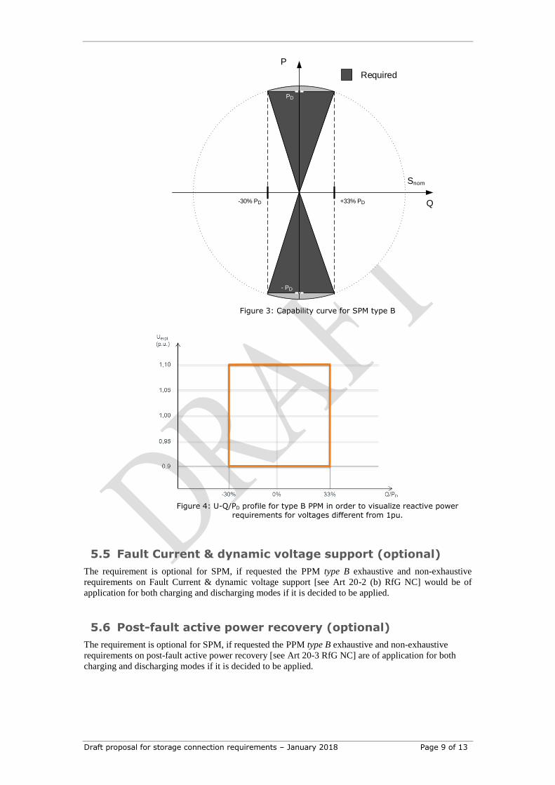
A SPM type B shall be capable of providing, like the PPM type B [see Art 20-2(a) RfG NC], the
reactive power capabilities determined by the Q-P profile as represented in the Figure 3 adapted for
both charging and discharging modes.
The limitations are based on nominal current at high active power and by a power factor (cos(phi))
defined by the 2 points at Q= -30% and +33% of PD, where PD is the maximum active power that can
be produced or absorbed in case of the maximum requested reactive power output (hence equal to
0.95*Snom). For voltage different from 1 p.u, the capabilities are defined as per the U-Q/PD profile
represented in Figure 4. Note that the available capability of the SPM (which could be wider than the
minimum requirement) should be communicated, demonstrated and put at disposal of the relevant
system operator. The owner of the SPM is not allowed to refuse the use of the reactive capability
without a technical justification. The SPM is therefore expected to not limit its capabilities to comply
with the minimum requirement but to use the full capability to support the system stability as stated in
its agreement. In case the SPM has already the capability of voltage regulation, one should not refuse
the relevant system operator to make use of it. In this case, the settings of the controllers should be
agreed with the relevant system operator.
Draft proposal for storage connection requirements – January 2018 Page 9 of 13
Q
P
PD
Snom
Required
- PD
+33% PD-30% PD
Figure 3: Capability curve for SPM type B
Figure 4: U-Q/PD profile for type B PPM in order to visualize reactive power
requirements for voltages different from 1pu.
5.5 Fault Current & dynamic voltage support (optional)
The requirement is optional for SPM, if requested the PPM type B exhaustive and non-exhaustive
requirements on Fault Current & dynamic voltage support [see Art 20-2 (b) RfG NC] would be of
application for both charging and discharging modes if it is decided to be applied.
5.6 Post-fault active power recovery (optional)
The requirement is optional for SPM, if requested the PPM type B exhaustive and non-exhaustive
requirements on post-fault active power recovery [see Art 20-3 RfG NC] are of application for both
charging and discharging modes if it is decided to be applied.
Draft proposal for storage connection requirements – January 2018 Page 10 of 13
6 SPM Type C
In addition to the specifications for SPM type B, the following is requested.
6.1 Frequency stability& Active Power management
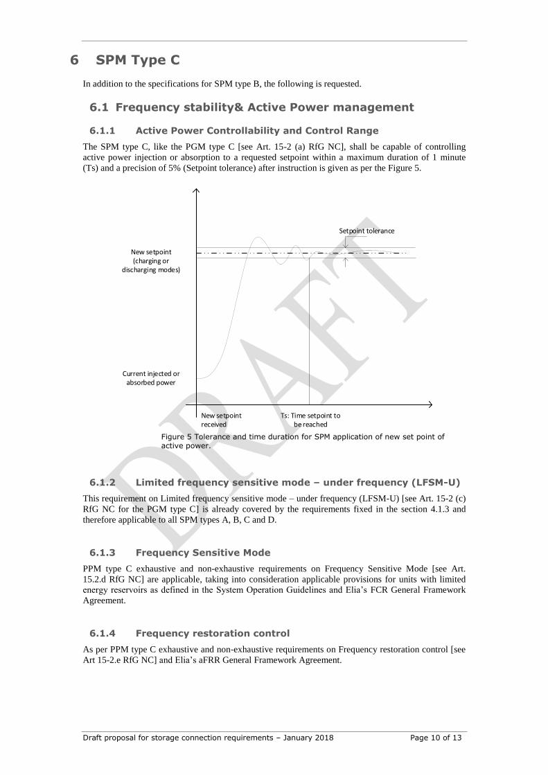
6.1.1 Active Power Controllability and Control Range
The SPM type C, like the PGM type C [see Art. 15-2 (a) RfG NC], shall be capable of controlling
active power injection or absorption to a requested setpoint within a maximum duration of 1 minute
(Ts) and a precision of 5% (Setpoint tolerance) after instruction is given as per the Figure 5.
Ts: Time setpoint to be reached
New setpoint(charging or
discharging modes)
Setpoint tolerance
New setpoint received
Current injected or absorbed power
Figure 5 Tolerance and time duration for SPM application of new set point of active power.
6.1.2 Limited frequency sensitive mode – under frequency (LFSM-U)
This requirement on Limited frequency sensitive mode – under frequency (LFSM-U) [see Art. 15-2 (c)
RfG NC for the PGM type C] is already covered by the requirements fixed in the section 4.1.3 and
therefore applicable to all SPM types A, B, C and D.
6.1.3 Frequency Sensitive Mode
PPM type C exhaustive and non-exhaustive requirements on Frequency Sensitive Mode [see Art.
15.2.d RfG NC] are applicable, taking into consideration applicable provisions for units with limited
energy reservoirs as defined in the System Operation Guidelines and Elia’s FCR General Framework
Agreement.
6.1.4 Frequency restoration control
As per PPM type C exhaustive and non-exhaustive requirements on Frequency restoration control [see
Art 15-2.e RfG NC] and Elia’s aFRR General Framework Agreement.
Draft proposal for storage connection requirements – January 2018 Page 11 of 13
6.1.5 Real-time monitoring of FSM
As per PPM type C exhaustive and non-exhaustive requirements on Real-time monitoring of FSM [see
Art 15-2.g RfG NC] and Elia’s General Framework Agreement.
6.1.1 Automatic disconnection for voltage outside ranges
As per PPM type C exhaustive and non-exhaustive requirements on Automatic disconnection for
voltage outside ranges [see Art 15-3 RfG NC].
6.2 System restoration
As per PPM type C exhaustive and non-exhaustive requirements on System restoration [see Art 15-5
RfG NC].
6.3 Reactive capabilities
This requirement should be met at the point of common coupling (POCC).
A type C SPM shall be capable of providing like the PPM Type C requirements [see Art 21-3(a-c) RfG
NC], the reactive power within the Q-P profile described in Figure 6 for both charging and discharging
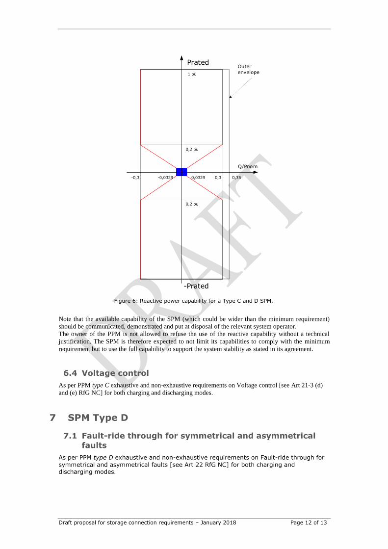
modes.. This profile has an obligated span of 0.6p.u. with regards to Q/Pnom, but can move within an
area of [-0.3p.u., +0.35p.u.] represented by the outer envelope when accepted by Elia (based on the
connection point, size and the characteristic of the SPM) as defined in the Figure 6.
Draft proposal for storage connection requirements – January 2018 Page 12 of 13
Figure 6: Reactive power capability for a Type C and D SPM.
Note that the available capability of the SPM (which could be wider than the minimum requirement)
should be communicated, demonstrated and put at disposal of the relevant system operator.
The owner of the PPM is not allowed to refuse the use of the reactive capability without a technical
justification. The SPM is therefore expected to not limit its capabilities to comply with the minimum
requirement but to use the full capability to support the system stability as stated in its agreement.
6.4 Voltage control
As per PPM type C exhaustive and non-exhaustive requirements on Voltage control [see Art 21-3 (d)
and (e) RfG NC] for both charging and discharging modes.
7 SPM Type D
7.1 Fault-ride through for symmetrical and asymmetrical
faults
As per PPM type D exhaustive and non-exhaustive requirements on Fault-ride through for
symmetrical and asymmetrical faults [see Art 22 RfG NC] for both charging and discharging modes.
1 pu
0,2 pu
0,2 pu
Q/Pnom
Prated
-Prated
Outer
envelope
0,3-0,3 -0,0329 0,0329 0,35
Draft proposal for storage connection requirements – January 2018 Page 13 of 13
8 References
[1] "‘Network Code Requirements for Generators’ or ‘NC RfG’: Commission Regulation (EU)
2016/631 of 14 April 2016 establishing a network code on requirements for grid connection of
generators,," http://eur-lex.europa.eu/legal-content/EN/TXT/?uri=OJ:JOL_2016_112_R_0001.
[2] "'Network Code on Demand Connection': Commission Regulation (EU) 2016/1388 of 17 August
2016 establishing a Network Code on Demand Connection".
[3] "Parameters of Non-exhaustive requirements: ENTSO-E Guidance document for national
implementation for network codes on grid connection".
[4] "'Network Code on Electricity Emergency and Restoration ': Commission Regulation (EU)
2017/2196 of 24 November 2017 establishing a network code on electricity emergency and
restoration," http://eur-lex.europa.eu/legal-
content/EN/TXT/PDF/?uri=CELEX:32017R2196&from=EN.