DRAFT PD686 - Precision Digital · 1. Loosen the four screws on the enclosure cover and remove the...
4
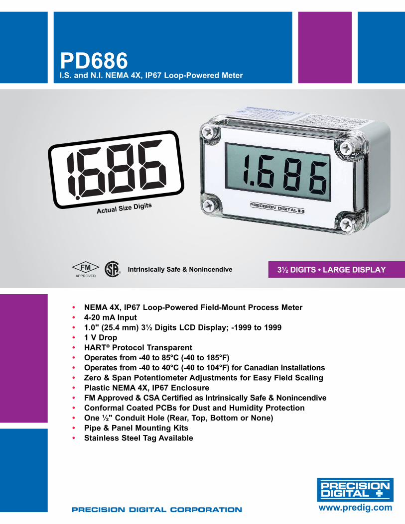
3½ Digits • LARgE DisPLAY PD686 i.s. and N.i. NEMA 4X, iP67 Loop-Powered Meter PRECISION DIGITAL CORPORATION www.predig.com D • NEMA 4X, iP67 Loop-Powered Field-Mount Process Meter • 4-20 mA input • 1.0" (25.4 mm) 3½ Digits LCD Display; -1999 to 1999 • 1 V Drop • HARt ® Protocol transparent • Operates from -40 to 85°C (-40 to 185°F) • Operates from -40 to 40°C (-40 to 104°F) for Canadian installations • Zero & span Potentiometer Adjustments for Easy Field scaling • Plastic NEMA 4X, iP67 Enclosure • FM Approved & CsA Certified as intrinsically safe & Nonincendive • Conformal Coated PCBs for Dust and Humidity Protection • One ½" Conduit Hole (Rear, top, Bottom or None) • Pipe & Panel Mounting Kits • stainless steel tag Available Actual size Digits intrinsically safe & Nonincendive
Transcript of DRAFT PD686 - Precision Digital · 1. Loosen the four screws on the enclosure cover and remove the...
3½ Digits • LARgE DisPLAY
PD686i.s. and N.i. NEMA 4X, iP67 Loop-Powered Meter
Precision Digital corPoration www.predig.com
DRAFT
• NEMA 4X, iP67 Loop-Powered Field-Mount Process Meter• 4-20 mA input• 1.0" (25.4 mm) 3½ Digits LCD Display; -1999 to 1999• 1 V Drop• HARt® Protocol transparent• Operates from -40 to 85°C (-40 to 185°F)• Operates from -40 to 40°C (-40 to 104°F) for Canadian installations• Zero & span Potentiometer Adjustments for Easy Field scaling• Plastic NEMA 4X, iP67 Enclosure• FM Approved & CsA Certified as intrinsically safe & Nonincendive• Conformal Coated PCBs for Dust and Humidity Protection• One ½" Conduit Hole (Rear, top, Bottom or None)• Pipe & Panel Mounting Kits• stainless steel tag Available
Actual size Digits
intrinsically safe & Nonincendive

PD686 i.s. and N.i. NEMA 4X, iP67 Loop-Powered Meter
www.predig.com2
OVERViEWThe PD686 is an FM Approved, CSA Certified intrinsically safe and nonincendive, NEMA 4X, IP67 loop-powered indicator that is easy to install and program. It can be seen from considerable distance and even in bright sunlight. The fact that this meter is loop-powered means that there is no need to run additional, costly power lines into a hazardous area. The meter gets all of the power it needs from the 4-20 mA loop and its 1 V drop results in a minimal burden on the loop. The meter features a wide -40 to +85°C operating temperature range and is available with a ½" conduit hole in a location of your choice for easy installation. Calibration is a quick two-step process involving the adjustment of only high and low, non-interacting potentiometers.
sPECiFiCAtiONsExcept where noted all specifications apply to operation at +25°C.
input: 4-20 mA @ 30 VDC maximumDisplay: 1.0" (25.4 mm) LCD, 3½ digits; -1999 to +1999Accuracy: ±0.1% FS ±1 countApprovals: FM Approved & CSA Certified as intrinsically safe with entity, for use in Class I, II and III, Division 1, Groups A, B, C, D, E, F, & G; T4; hazardous locations. Nonincendive for use in Class I, Division 2, Groups A, B, C and D. Suitable for use in Class II and III, Division 2, Groups F and GFM certificate number: 3016598. CSA certificate number: 1111348Additional FM Approvals: Intrinsically Safe, Class I, Zone 0, Group IICSee Control Drawing LIM686-2 (Dwg No 1155) for complete installation instructions
Entity Parameters: Vmax= 30 V, Imax = 175 mA, Ci = 0 µF, Li = 0 µH, Pi = 1.3 WDecimal Point: User selectableCalibration: Two-step; non-interacting zero and spanCalibration Range: 4 mA input: -1000 to +1000;20 mA input: between 20 and 2000 counts > 4 mA displayDisplay Update Rate: 2.5/secondMaximum input Current: 30 mAMaximum Voltage Drop: 1 V @ 20 mAOperating temperature: -40 to 85°Cfor Canadian installations -40 to 40°C. storage temperature: -40 to 85°CRelative Humidity: 0 to 90% non-condensing. Printed circuit boards are conformally coated.Enclosure: Impact-resistant glass filled polycarbonate body, color: gray; impact-resistant clear polycarbonate cover; NEMA 4X, IP67 Connections: Removable screw terminals accept 12 to 26 AWGConduit Hole: One ½" conduit hole provided, see Ordering Info.Weight: 12 oz (340 g) Warranty: 2 years parts & labor
COMPLiANCE iNFORMAtiONProduct Markings:
Max Loop Voltage: 30 V; Max Loop Current: 30 mAInstall per Control Drawing 1155; Enclosure: Type 4XEntity: Ui : 30 V; Ii : 175 mA; Ci : 0; Li : 0; Pi : 1.3 WINTRINSICALLY SAFE (SÉCURITÉ INTRINSÈQUE)CLASS I, DIV. 1, GROUPS A,B,C,D T4CLASS II, DIV. 1, GROUPS E,F,G; CLASS III, DIV. 1SUITABLE FOR CLASS I, DIV. 2, GROUPS A,B,C,DCLASS II, DIV. 2, GROUPS F,G; CLASS III, DIV. 2USA: IS CLASS I ZONE 0 AEx ia IIC T4Maximum ambient temperature: 185°F (85°C)Canada: Maximum ambient temperature: 40°C
special Conditions for safe Use: The product shall be installed in compliance with the enclosure, mounting, spacing and segregation requirements of the ultimate application including a tool removable cover.
Description: Intrinsically Safe for use in Class I, II and III, Division 1, Groups A, B, C, D, E, F and G and Class I, Zone 0 (approved for Zone 0 in U.S. only), Group IIC in accordance with Entity requirements and Control Drawing 1155; Nonincendive for use in Class I, Division 2, Groups A, B, C and D; Suitable for use in Class II and III, Division 2, Groups F and G Indoor and Outdoor, Type 4X Hazardous (Classified) Locations.
1. Read complete instructions prior to installation and operation of the meter.2. Installation and service should be performed only by trained service personnel.3. For Class II, Class III (Division 1 and 2) and NEMA/CSA type 4X installations, use
conduit hub which is listed/certified for the environment in which the indicator is installed.4. For Class II and III (Division 1 and 2) installations, field wiring must enter the enclosure
through a listed/certified dust-tight conduit seal.5. Control room equipment must not use or generate more than 250 VRMS or VDC.6. US installations must be in accordance with ANSI/ISA RP12.06.01 “Installation of
Intrinsically Safe Systems for Hazardous (Classified) Locations” and the National Electrical Code (ANSI/NFPA 70). Canadian installations must be in accordance with the Canadian Electrical Code, Part 1.
7. Hazardous location installation instructions for associated apparatus (barrier) must also be followed when installing this equipment.
8. For safe installation of a FM Approved/CSA Certified transmitter in series with PD686 loop indicator, the hazardous location installation instructions for the transmitter, PD686 loop indicator, and associated apparatus (barrier) must be compatible.
9. PD686 indicator does not add capacitance or inductance to loop under normal or fault conditions.
10. Substitution of components may impair hazardous location safety.
! safety information
Conduit installation instructions1. Remove the printed circuit board from the enclosure. 2. Connect appropriate size conduit fittings to the hole provided.
For enclosures without a pre-drilled hole, the installer must make a hole in accordance with the instructions for the particular conduit fitting being installed.
3. Connect conduit (with attached hubs) to the enclosure. Conduit hubs must be connected to the conduit prior to being connected to the enclosure. Use only conduit hubs that are designed to maintain NEMA 4X or IP67 ratings.
Note: Please read FM Approved & CSA Certified Loop-Powered Meter Intrinsic Safety Barrier Connections (LIM686-2, Dwg No 1155) – for more information pertaining to the conduit holes.
Mounting instructions1. Remove the enclosure cover from the base. 2. Insert mounting hardware into mounting holes in enclosure
base (see Figure 4). 3. Secure the enclosure base to the mounting surface using the
inserted hardware. 4. Re-attach the enclosure cover to the base.
sEtUPThe only tools needed for calibration are a calibrated current source and a small slotted / flathead screwdriver.Calibration ConnectionsTo access the input terminals it is necessary to remove the enclosure cover and the Display PCB. This is done by loosening the four screws on the enclosure cover and removing the cover. Completely loosen the left screw that holds the Display PCB to the enclosure and loosen the right screw about four turns so the Display PCB remains attached to the enclosure. Rotate the Display PCB 90° to gain access to the Input Signal PCB. Next, connect a calibrated current source per Figure 1.
PD686 i.s. and N.i. NEMA 4X, iP67 Loop-Powered Meter
www.predig.com3
Decimal Point selectionThe decimal point jumper array is located in the lower right corner of the Display PCB next to the display. It is labeled DP1, DP2, DP3. Place a jumper over both pins of DP1 for a display of 199.9, DP2 for 19.99, or DP3 for 1.999.
CalibrationLO and HI calibration controls are located to the left of the display (see Figure 1). Apply a signal equal to 4 mA and adjust the LO control to display the desired reading. Apply a signal between 16 and 20 mA and adjust the HI control to display the desired reading. Complete the calibration procedure by making any minor adjustments to the LO and HI controls.
installationInstallation of the meter involves removing the Display PCB from its enclosure and connecting a ½" conduit fitting to the hole provided. Refer to PD686 FM Approved & CSA Certified Loop-Powered Meter Intrinsic Safety Barrier Connections diagrams (LIM686-2, Dwg No 1155) for further details. Wall mounting holes are located in each corner of the enclosure (see Figure 4).
Loop ConnectionsDisconnect power to the loop and install the meter as illustrated in Figure 2 and the PD686 FM Approved & CSA Certified Loop-Powered Meter Intrinsic Safety Barrier Connections diagrams (LIM686-2, Dwg No 1155) supplied with the instrument. Replace the enclosure cover.
Removing Display PCB From the LoopThe Display PCB and Input Signal PCB are connected together with one black and one red wire. The wires are soldered to the Display PCB and connected to a screw terminal connector on the Input Signal PCB.to remove Display PCB:1. Loosen the four screws on the enclosure cover and remove the
cover from the enclosure base.2. Completely loosen the left-side screw holding the Display PCB
to the enclosure and loosen the right-side screw four turns so the Display PCB remains secure to the enclosure.
3. Rotate the Display PCB 90° to gain access to the Input Signal PCB. 4. Install Loop Jumper over both pins to bypass Display PCB and
allow the signal to flow through the Loop Jumper. The display turns off when jumper is installed.
5. Disconnect the black and red signal wires from the screw terminal connector.
6. Loosen completely the right-side screw and lift Display PCB from enclosure. Care should be taken to prevent static electricity from damaging the electronic circuitry.
7. Restore enclosure cover to the base to prevent contamination of components.
Restoring Display PCB to the Loop1. Remove enclosure cover as described above in step 1.2. Secure Display PCB to enclosure using right-side screw; do
not tighten screw to allow rotation of Display PCB while ac-cessing Input Signal PCB.
3. Connect red wire to S+ terminal and black wire to S- terminal, as shown in Figure 1.
4. Remove Loop Jumper to allow the signal to flow through Dis-play PCB (save push-on jumper by placing over one pin only).
5. Tighten screws holding Display PCB and install enclosure cover.
servicing Display PCB Outside the LoopTwo modes of input signal allow the user to remove the Display PCB for service without interrupting the loop as indicated above and operate the Display PCB at another location in a non-hazardous area. The loop remains connected to the Input Signal PCB while the Display PCB is absent for service. The user may operate the Display PCB at another location by connecting a signal to “S+” and “S-” wires on the Display PCB. Refer to Figure 3.
CONNECtiONs
Figure 1: Calibrator Connected to input signal PCB
Figure 2: Control Loop Connected to input signal PCB
Figure 3: Calibrator Connected to Display PCBThe display PCB may be removed from the enclosure for bench calibration. Loop Jumper must be installed on Input Signal PCB
to maintain loop, refer to procedures below.
LO CALIBRATION CONTROLHI CALIBRATION CONTROLBALANCE CONTROL(factory adjust only)
DISPLAY PCB COMPONENT SIDE(may be removed for bench calibration)
S-
S-
S-
S+
S+
S+
BLACK
RED
LOOP JUMPER
CALIBRATEDCURRENT SOURCE
INPUT SIGNAL PCB(mounted to base of enclosure)
+ -
DP1DP2DP3
INPUT SIGNAL PCB
LOOP JUMPER(remove when Display PCB is connected)
TRANSMITTER
HAZARDOUS AREA NON-HAZARDOUS AREA
POWERSUPPLY+ +-
-4-20mA
S+ S+S- S- Field wiring ismade to theInput Signal PCBwhich is mountedto the base ofthe enclosure.
S+ S-
DISPLAY PCB COMPONENT SIDE
CALIBRATEDCURRENT SOURCE
DP1DP2DP3
The Display PCB may be removed from the enclosure for bench calibration. Loop Jumper must be installed
on Input Signal PCB to maintain loop,refer to procedures below.

PD686 i.s. and N.i. NEMA 4X, iP67 Loop-Powered Meter
www.predig.com
LIM686_G 10/18
Precision Digital corPoration233 south street • Hopkinton MA 01748 UsA • tel (800) 343-1001 • Fax (508) 655-8990
DisclaimerThe information contained in this document is subject to change without notice. Precision Digital Corporation makes no representations or warranties with respect to the contents hereof, and specifically disclaims any implied warranties of merchantability or fitness for a particular purpose.
©2018 Precision Digital Corporation. All rights reserved.
AccessoriesModel Description
PDA6844 Panel Mount Kit (Does not provide NEMA 4X seal to panel)
PDA6845 2" Pipe Mounting Kit (zinc plated steel)
PDA6845-SS 2" Pipe Mounting Kit (stainless steel)
PDA-SSTAG Stainless Steel Tag
ORDERiNg iNFORMAtiONDiMENsiONs
A: 3.15" (80 mm) C: 2.36" (60 mm) E: 2.56" (65 mm) B: 5.51" (140 mm) D: 4.72" (120 mm) F: 0.79" (20 mm)
Your Local Distributor is:
MOUNtiNg Pipe Mounting KitThe PDA6845 is a pipe mounting kit with two mounting holes. It provides all of the necessary hardware to mount the PD686 to a 2" pipe. It is available in zinc plated and stainless steel materials.
Mounting Plate
U-bolt KitHex Nut
Meter not included.
Stainless Steel TagsLaser Etched ● Up To 46 Characters ● Lead Seal & Wire
BUY NOW Atwww.predig.com/pda-sstag
Panel Mounting KitThe PDA6844 is a panel mounting kit for the PD686. It provides all of the necessary hardware to mount the PD686 meter to an equipment panel. This panel mounting kit is not intended to provide waterproof protection to the panel.
Figure 4: Dimensions and Wall Mounting information
SIDE VIEW
Wall MountingHoles BeneathCover Screws
E
F
FRONT VIEW
D
A C
B
Figure 4Dimensions and Wall Mounting Information
PD686 i.s. & N.i. NEMA 4X, iP67 Loop-Powered Meter
Model Description Conduit Hole Location for
½" Fitting PD686 FM Approved & CSA Certified Intrinsically
Safe & Nonincendive, NEMA 4X, IP67 Loop-Powered Meter with Conduit Hole Location in Bottom of Enclosure
Bottom
PD686-X FM Approved & CSA Certified Intrinsically Safe & Nonincendive, NEMA 4X, IP67 Loop-Powered Meter with Conduit Hole Location in Rear of Enclosure
Rear
PD686-Y FM Approved & CSA Certified Intrinsically Safe & Nonincendive, NEMA 4X, IP67 Loop-Powered Meter with Conduit Hole Location in Top of Enclosure
Top
PD686-Z FM Approved & CSA Certified Intrinsically Safe & Nonincendive, NEMA 4X, IP67 Loop-Powered Meter with no Conduit Hole
None


![OptiPlex 3040 - Mini Tower Owner's Manual2. To remove the cover: a. Loosen the captive screws that secure the cover to the computer [1]. b. Slide the cover forward and lift it away](https://static.fdocuments.in/doc/165x107/603e726452949726a837b08a/optiplex-3040-mini-tower-owners-manual-2-to-remove-the-cover-a-loosen-the.jpg)