DRAFT MALAYSIAN 11M003R0 STANDARD - · PDF fileDRAFT MALAYSIAN 11M003R0 STANDARD ... 8 Fire...
74
DRAFT MALAYSIAN 11M003R0 STANDARD STAGE : PUBLIC COMMENT (40.20) DATE : 01/07/2014 – 31/08/2014 Fixed fire fighting systems - Fire pumps OFFICER/SUPPORT STAFF: (NA / ) ICS: 23.040.01 Descriptors: hose reels, foam inlets, design, installation © Copyright DEPARTMENT OF STANDARDS MALAYSIA For Public Comment
Transcript of DRAFT MALAYSIAN 11M003R0 STANDARD - · PDF fileDRAFT MALAYSIAN 11M003R0 STANDARD ... 8 Fire...
DRAFT
MALAYSIAN 11M003R0
STANDARD
STAGE : PUBLIC COMMENT (40.20) DATE : 01/07/2014 – 31/08/2014
Fixed fire fighting systems - Fire pumps OFFICER/SUPPORT STAFF: (NA / )
ICS: 23.040.01 Descriptors: hose reels, foam inlets, design, installation
© Copyright
DEPARTMENT OF STANDARDS MALAYSIA
For Pub
lic Com
ment

For Pub
lic Com
ment
11M003R0
© STANDARDS MALAYSIA 2014 - All rights reserved i
Contents
Page Committee representation ................................................................................................. ii Foreword ............................................................................................................................ iii Introduction ........................................................................................................................ iv 1 Scope .................................................................................................................... 1
2 Normative References ......................................................................................... 1 3 Definitions ............................................................................................................ 2 4 Water Supplies ..................................................................................................... 6 5 General Requirements for Fire Pumps ................................................................. 8 6 Specific Requirements for Fire Pumps ................................................................. 23 7 Requirements for Pressure Maintenance Pumps................................................. 31 8 Fire Hose Reel Pumpsets ..................................................................................... 36 9 Electric Drivers and Controllers ............................................................................ 39 10 Compression-Ignition Drivers and Controllers ...................................................... 45 11 Shop Testing and Certification ............................................................................. 59 12 Siting and Installation ........................................................................................... 63 13 Commissioning Tests .......................................................................................... 65 Annex A Wiring systems rating ......................................................................................... 71 Bibliography ....................................................................................................................... 73
For Pub
lic Com
ment
11M003R0
© STANDARDS MALAYSIA 2014 - All rights reserved ii
Committee representation The Fire Safety and Prevention Industry Standards Committee (ISC M) under whose authority this Malaysian Standard was developed, comprises representatives from the following organisations:
Association of Consulting Engineers Malaysia Construction Industry Development Board Malaysia Department of Chemistry, Malaysia Department of Standards Malaysia Forest Research Institute Malaysia Jabatan Bomba dan Penyelamat Malaysia Jabatan Kerja Raya Malaysia Kementerian Perdagangan Dalam Negeri, Koperasi Dan Kepenggunaan Malaysian Association of Standards Users Malaysian Fire Protection Association Master Builders Association Malaysia Persatuan Insuran Am Malaysia Pertubuhan Akitek Malaysia Real Estate and Housing Developers' Association Malaysia SIRIM Berhad (Secretariat) SIRIM QAS International Sdn Bhd Tenaga Nasional Berhad (Bahagian Pembahagian) The Institution of Engineers, Malaysia The Institution of Fire Engineers (UK) Malaysia Branch Universiti Kebangsaan Malaysia Universiti Putra Malaysia
The Technical Committee on Wet Fire Protection System which developed this Malaysian Standard consists of representatives from the following organisations:
Association of Consulting Engineers Malaysia Jabatan Bomba dan Penyelamat Malaysia Jabatan Kerja Raya Malaysia Kolling Engineering Sdn Bhd Malaysian Fire Protection Association Pertubuhan Akitek Malaysia SIRIM Berhad (Secretariat) SIRIM QAS International Sdn Bhd (Fire Protection Section) SIRIM QAS International Sdn Bhd (Product Certification and Inspection Department) Tenaga Nasional Berhad The Institution of Engineers, Malaysia The Institution of Fire Engineers (UK) Malaysia Branch Universiti Putra Malaysia
For Pub
lic Com
ment

11M003R0
© STANDARDS MALAYSIA 2014 - All rights reserved iii
Foreword This Malaysian Standard was developed by the Technical Committee on Wet Fire Protection System under the authority of the Industry Standards Committee on Fire Safety and Prevention. Compliance with a Malaysian Standard does not of itself confer immunity from legal obligations.
For Pub
lic Com
ment
11M003R0
© STANDARDS MALAYSIA 2014 - All rights reserved iv
Introduction This Malaysian Standard corresponds to AS 2941- Fixed Fire Protection Installation - Pumpset Systems and is intended to be used in conjunction with the following: a) MS 1489-1, Fire extinguishing installations and equipment - Part 1:Hose reels and foam
inlets
b) MS 1489-2, Fire extinguishing installations and equipment - Part 2: Wet and dry fire fighting mains
c) MS 1910, Fixed firefighting systems - Automatic sprinkler systems - Design, installation
and maintenance The purpose of this standard is to provide a reasonable degree of protection for life and property from fire through installation requirements for fire pumpsets based on sound engineering principles, test data and field experience.
Requirements are established for the selection, installation and operation of fire pumps, pump drivers and associated equipment. However, the standard does not consider the number, disposition or types of driver considered appropriate for a given fixed fire protection system. The term 'driver' is used in lieu of the term 'engine'.
For Pub
lic Com
ment
11M003R0
© STANDARDS MALAYSIA 2014 - All rights reserved 1
Fixed fire fighting systems - Fire pumps
1 Scope This Malaysia Standard specifies the minimum requirements for the design, manufacture, installation, testing and commissioning of fire pumpsets. This standard specifies requirements for totally independent pumpset systems, for use with fixed fire protection installations such as sprinkler, hydrant, water spray, deluge, pre-action foam and hose reel systems. It covers water supplies, pumps, drivers, fire pump controllers, and auxiliary equipment. Requirements for siting, installation, testing and commissioning including acceptance testing for electrical and compression-ignition drivers are also included.
2 Normative references The following referenced documents are indispensable for the application of this document. For dated references, only the edition cited applies. For undated references, the latest edition of the referenced document (including any amendments) applies. MS 1910, Fixed firefighting systems - Automatic sprinkler systems - Design, installation and maintenance MS ISO 68-1, ISO General purpose metric screw threads - Basic profile Part 1: Metric screw threads MS IEC 60034, Rotating electrical machines (all parts) MS IEC 60034-12, Rotating electrical machines - Part 12: Starting performance of single-speed three-phase cage induction motors MS IEC 60072-1, Dimensions and output series for rotating electrical machines - Part 1: Frame numbers 56 to 400 and flange numbers 55 to 1080 MS IEC 60072-2, Dimensions and output series for rotating electrical machines - PART 2: Frame numbers 355 to 1000 and flange numbers 1180 to 2360 MS IEC 60364, Electrical installations of buildings (all parts) MS IEC 60529, Degree of protection provided by enclosures (IP code) MS IEC 60947, Low-voltage switchgear and controlgear (all parts) MS IEC 60947-2, Low-voltage switchgear and controlgear - Part 2: Circuit-breakers MS IEC 60947-4-1, Low-voltage switchgear and controlgear - Part 4-1: Contactors and motor- starters - Electromechanical contactors and motor-starters MS IEC 60947-4-2, Low-voltage switchgear and controlgear - Part 4-2: Contactors and motor-starters - AC semiconductor motor controllers and starters ISO 281, Rolling bearings - Dynamic load ratings and rating life
For Pub
lic Com
ment
11M003R0
© STANDARDS MALAYSIA 2014 - All rights reserved 2
ISO 1940-1, Mechanical vibration - Balance quality requirements for rotors in a constant (rigid) state - Part 1: Specification and verification of balance tolerances ISO 2858, End-suction centrifugal pumps (rating 16 bar) - Designation, nominal duty point and dimensions ISO 9906:2012, Rotodynamic pumps - Hydraulic performance acceptance tests - Grades 1, 2 and 3 ISO 15550, Internal combustion engines - Determination and method for the measurement of engine power - General requirements IEC 60072-3, Dimensions and output series for rotating electrical machines - Part 3: Small built-in motors - Flange numbers BF10 to BF50 AS 3570, Automotive diesel fuel BS 1780, Specification for bourdon tube pressure and vacuum gauges BS EN 1092, Flanges and their joints - Circular flanges for pipes, valves, fittings and accessories (all parts) BS EN 1171, Specification for cast iron gate valves BS 5154, Specification for copper alloy globe, globe stop and check, check and gate valves DIN 24255, Standard centrifugal end suction EN 733, End-suction centrifugal pumps, rating with 10 bar with bearing bracket - Nominal duty point, main dimensions, designation system
3 Terms and definitions For the purpose of this standard, the following term and definitions apply. 3.1 circulation relief Prevention of overheating by providing a flow of water to waste when the pump is operating with no discharge. 3.2 controller An enclosed group of devices (including a power disconnect device by which the conductors of a circuit can be disconnected from the source of supply) that serves to govern, in some predetermined manner, the electric power delivered to the apparatus to which it is connected. 3.3 discharge head (assembly) Part of the vertical line shaft pump assembly that supports the driver, pump and column, aligns the driver and pump, and changes the vertical flow to a horizontal direction.
For Pub
lic Com
ment
11M003R0
© STANDARDS MALAYSIA 2014 - All rights reserved 3
3.4 driver An engine or motor used to drive a fire pump. 3.5 duty point Head (duty head) corresponding to the required flow (duty flow) for the particular application. 3.6 duty speed The speed at duty point (see Clause 3.5). 3.7 dynamic shaft deflection The distance by which the axial centre-line of the shaft deviates from the axial centre-line of the bearings under dynamic conditions. 3.8 efficiency The ratio of the energy delivered by the pump to the energy supplied to the pump shaft, that is, liquid power divided by applied power. 3.9 fixed guard Guard kept in place by means of fasteners (screws, nuts, etc.), making removal or opening impossible without using tools. 3.10 hollow shaft The hollow drive shaft fitted to electric motors or right-angle gear drives to accept the solid shaft of the pump. NOTE. The hollow shaft design facilitates impeller adjustment within the bowl assembly and the installation of a non-reverse ratchet in the motor or gear drive.
3.11 inertia base A supporting base, isolated from the main structure that increases the mass of the non-rotating parts to dampen any vibratory forces due to rotation. 3.12 line shaft A vertical shaft that transmits the power from a driver to a vertical turbine pump 3.13 listed Refers to a product listed for fire protection duty by an internationally recognized testing laboratory or approval body. 3.14 maximum allowable pump working pressure The maximum working pressure for which a pump casing is designed.
For Pub
lic Com
ment
11M003R0
© STANDARDS MALAYSIA 2014 - All rights reserved 4
3.15 net positive suction head (NPSH) The total inlet head plus the head corresponding to the atmospheric pressure minus the head corresponding to the vapour pressure. NOTE. `NPSH' and 'total inlet head' are referred to in the reference plane. The two references to NPSH are as follows: 1. Net positive suction head required (NPSHR) - A function of pump design, which is available from
the pump manufacturer. 2. Net positive suction head available (NPSHA) - A function of the system in which the pump operates
and which can be calculated for any installation.
3.16 nominal size (DN) A numerical designation of size that is common to all components in a piping system other than components designated by outside diameters or by thread size. NOTE. The nominal size is designated by DN followed by a number. The nominal size cannot be measured, and should not be used for the purposes of calculation. It should be noted that not all piping components are designated by nominal size, for example, steel tubes are designated and ordered by outside diameter and thickness. It is a convenient round number for reference purposes and is only loosely related to manufacturing dimensions.
3.17 non-reverse ratchet A mechanism installed to prevent reverse rotation of the pump-driver assembly. 3.18 oil-lubricated vertical turbine pump A turbine pump in which the vertical line shaft is enclosed and the shaft bearings are lubricated with oil. 3.19 pressure relief The prevention of over-pressurization of the system to which the pump is connected. 3.20 pump manufacturer An entity that designs, manufactures, tests and certifies a pump as compliant with this Standard. 3.21 pumpset An assembly comprising a pump, a driver, a coupling and ancillary components on a common mounting base together with an integral or separate fire pump controller 3.22 pumpset manufacturer An entity that designs, manufactures, tests and certifies a complete assembly of pump, driver and controller as compliant with this standard.
For Pub
lic Com
ment
11M003R0
© STANDARDS MALAYSIA 2014 - All rights reserved 5
3.23 recirculation The phenomenon of flow reversal at the suction or discharge tips of the impeller vanes, which occurs when the capacity of the pump has been reduced by throttling. 3.24 reference plane The horizontal plane through the centre of the circle described by the external point of the entrance edges of the impeller blades. NOTE. For double-inlet pumps, the plane is taken through the higher centre.
3.25 relevant authority Director General of the Fire and Rescue Department, or other public authority having power to issue regulations, orders or other instructions in respect of any subject covered by this standard. NOTE. Where compliance with this standard is not a requirement of a relevant authority but is a requirement of a body such as an insurance company or association, then that body, or its nominees, may perform the functions of the relevant authority for the purposes of this standard.
3.26 sealed valve-regulated lead-acid (VRLA) battery Valve regulated (sealed) lead acid batteries that allow a small amount of venting but where the electrolyte cannot be tested or topped up. 3.27 total discharge head The reading of a gauge at the discharge flange, converted to metres of liquid and corrected to the pump centre-line, plus the velocity head at the point of gauge attachment. 3.28 total head (of a pump) The algebraic difference between the total discharge head and the total suction head. 3.29 total suction head The reading of a gauge at the suction flange, converted to metres of liquid and corrected to the pump centre-line, plus the velocity head at the point of gauge attachment. 3.30 variable speed control A speed control system used to limit the total discharge head by reducing the pump driver speed from duty speed; that is, the speed at duty point at minimum inlet pressure.
For Pub
lic Com
ment
11M003R0
© STANDARDS MALAYSIA 2014 - All rights reserved 6
3.31 velocity head The kinetic energy per unit mass of the liquid in movement. It is expressed by
v2 2g
where
v = mean velocity of the liquid in the section considered, in metres per second; and
g = acceleration of free fall, in metres per second squared.
4 Water Supplies 4.1 General The suitability and dependability of the source of water shall be determined prior to the selection of pumping equipment. 4.2 Acceptable sources of supply Sources of supply shall comply with the requirements of the Authority Having Jurisdiction applicable to the system served by the pumpset. Bores are no longer considered acceptable primary water supplies for fixed fire protection installation pumpset systems and should not be used. 4.3 Quality of water If the water contains dissolved or suspended matter likely to cause accumulation, pump materials shall be selected with due regard to the quality of water. See Clause 6.1.2 for materials of construction. 4.4 Flooded suction Fire protection pumps shall be supplied with flooded suction for intake of water as far as possible. Priming tanks or vacuum systems shall be provided for automatic priming of pumps installed under suction lift conditions. 4.5 Suction Lift Suction lift is the condition when suction pressure is below atmosphere. The total lift is the algebraic sum of the gauge reading at the suction flange of the pump, referring to the pump centerline and the velocity head at the point of gauge attachment. 4.6 Suction size The size of the suction pipe for single or multiple pumps (arranged to operate simultaneously) shall be such that with all pumps operating at maximum flow, the net positive suction head available (NPSHA) at the pump inlet shall be at least 1.0 m in excess of net positive suction head required (NPSHR) under all supply conditions. The NPSHA shall be reduced by 0.1 m at the pump installation for each 100 m above sea level.
For Pub
lic Com
ment
11M003R0
© STANDARDS MALAYSIA 2014 - All rights reserved 7
NOTES: 1 For pipe sizes see Table 5.1. 2 High-flow, high-speed centrifugal pumps typically have high-end NPSHR requirements. When such
pumps are drawing maximum flow from water storage tanks at minimum effective water level, it is generally recommended that NPSHR be less than 7.0 m.
4.7 Devices on suction piping With the exception of an approved valve for isolation purposes, no device that will adversely affect the performance of the pump shall be installed in the suction piping. NOTE. Prohibited devices include check valves, butterfly valves, globe valves and flow switches.
Valves within 15 pipe diameters of the pump inlet shall not be of the butterfly valve type. Where the water supply is obtained from an open source such as a pond or wet pit, a compatible corrosion-resistant strainer shall be attached to the suction inlet and shall have a free area of not less than four times the area of the suction entry. Individual openings in the strainer shall be not greater than the pump impellor passage width, up to a maximum allowance of 8 mm by 8 mm. 4.8 Priming for Pump under suction lift Where positive suction is not possible and the pump has to take suction under lift, adequate, reliable priming shall be provided.
Two means of automatic priming should be provided for the pump at the suction side. The priming could be a combination of the following:
a) An elevated, manual filled tank of at least 2.0 m3 inside the pump room.
b) An elevated, automatic refilling tank of at least 0.5 m3 inside the pump room.
c) A connection of at least 32 mm to a domestic water supply.
d) A connection of at least 25 mm to an industrial water supply.
e) A connection of at least 32 mm to gravity feed water supply (domestic or industrial) system.
NOTE. This section will not apply to vertical shaft turbine pump or wet pit vertical shaft pump turbine pump.
Each pump shall be fitted with a separate automatic priming arrangement. The arrangement shall consist of a tank situated at a higher level than the pump and with a pipe connection sloping from the tank to the delivery side of the pump. A non-return valve shall be fitted to this connection. The tank, the pump and the suction pipework shall be kept constantly full of water even where there is leakage from the foot valve. Should the water level in the tank fall to 2/3 of the normal level, the pump shall start.
For Pub
lic Com
ment
11M003R0
© STANDARDS MALAYSIA 2014 - All rights reserved 8
The size of the priming tank shall be minimum 500 L and the priming pipe shall be minimum 50 mm in diameter.
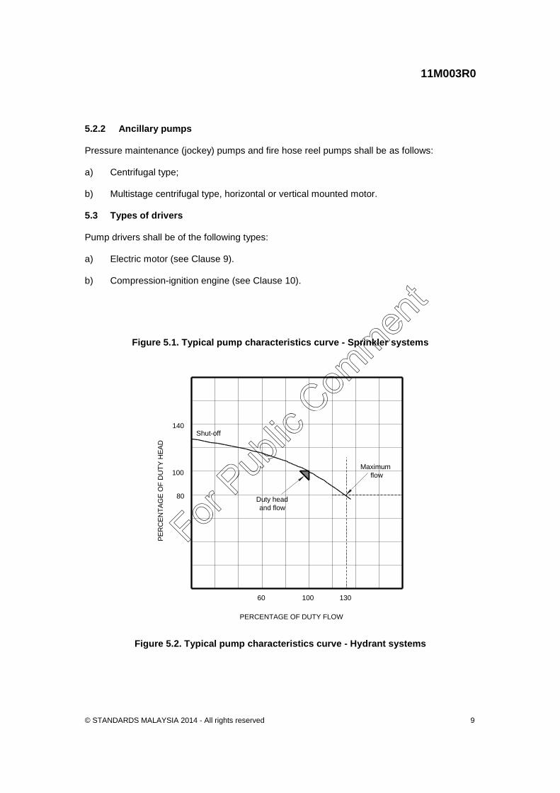
5 General requirements for fire pumpsets 5.1 Performance characteristics 5.1.1 General The performance characteristics of pumpsets for fixed fire protection systems shall be such that they provide the duty flow at the duty head and that the pressure falls progressively with an increase in rate of flow. Centrifugal pumps, other than those required for automatic fire sprinkler systems complying with MS 1910, shall be capable of providing a flow of 130 % of duty flow at not less than 80 % of duty head, NOTE. For typical pump characteristic curves, see Figure 5.1 and Figure 5.2.
The following requirements apply: a) For sprinkler systems, the duty head shall be the hydraulically most remote demand
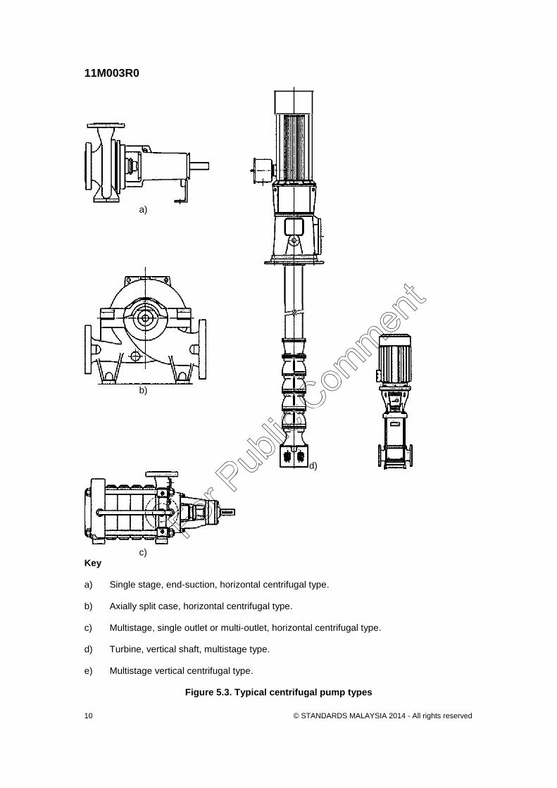
point + 50 kPa (see Figure 5.1). b) For hydrant systems, the duty head shall be the duty demand point (see Figure 5.2). A pump shall not exceed 140 % of its duty head at shut-off point or at any other point along its characteristic curve. Where two or more pumpsets operate in parallel, the pump performance characteristics shall be compatible. The net pump shut-off (churn) pressure plus the maximum static suction pressure, adjusted for elevation, shall not exceed the pressure for which the system components are rated. Pressure-relief valves shall not be used for this purpose. 5.2 Pump types 5.2.1 Fire protection pumps Fire protection pumps with the exception of positive displacement pumps used for water mist and foam injection systems, shall be centrifugal and selected from the following types: a) Single-stage, end-suction, horizontal or vertical shaft pump.
b) Axially split case, horizontal or vertical shaft pump.
c) Multistage, single outlet or multi-outlet, horizontal shaft pump.
d) Turbine, vertical shaft pump. NOTE. Typical pump types are illustrated in Figure 5.3.
For Pub
lic Com
ment
11M003R0
© STANDARDS MALAYSIA 2014 - All rights reserved 9
5.2.2 Ancillary pumps Pressure maintenance (jockey) pumps and fire hose reel pumps shall be as follows: a) Centrifugal type;
b) Multistage centrifugal type, horizontal or vertical mounted motor. 5.3 Types of drivers Pump drivers shall be of the following types: a) Electric motor (see Clause 9).
b) Compression-ignition engine (see Clause 10).
Figure 5.1. Typical pump characteristics curve - Sprinkler systems
60
80
100
140
100 130
PERCENTAGE OF DUTY FLOW
PE
RC
EN
TA
GE
OF
DU
TY
HE
AD
Shut-off
Maximum
flow
Duty head
and flow
Figure 5.2. Typical pump characteristics curve - Hydrant systems
For Pub
lic Com
ment
11M003R0
© STANDARDS MALAYSIA 2014 - All rights reserved 10
a)
b)
d) (e)
c)
Key a) Single stage, end-suction, horizontal centrifugal type.
b) Axially split case, horizontal centrifugal type.
c) Multistage, single outlet or multi-outlet, horizontal centrifugal type.
d) Turbine, vertical shaft, multistage type.
e) Multistage vertical centrifugal type.
Figure 5.3. Typical centrifugal pump types
For Pub
lic Com
ment
11M003R0
© STANDARDS MALAYSIA 2014 - All rights reserved 11
5.4 Pump/Driver Connection Each pump shall be flexibly coupled to a single driver. The coupling, or drive shaft with universal joints, shall be rated to the maximum driver output over the potential speed range and be such that either the pump or the driver can be removed separately without disturbing the other. Couplings shall be of a type that cannot disengage in service and continue to function in the event of failure of any flexible element. Chain drives, belt drives, clutch drives, elastomeric drives or fluid drives shall not be used except for positive displacement pumps. Dual-drive pumpsets shall not be used. Centrifugal pumps shall not be connected to the driver through a gearbox except where a right-angle drive is necessary. NOTES: 1 Couplings shall be fully enclosed by fixed guards that are tight fitting (to prevent access by hands
and/or fingers) and of sufficient strength to resist low velocity impacts from persons and high velocity impacts from broken parts.
2. A torsional vibration analysis may be required for high powered and/or low speed compression
ignition driver conducted on all applications to ensure the drive shaft system as described will not cause damage.
5.5 Baseplate Unless it is impracticable, the pump and driver shall be mounted on a common baseplate which shall be mounted on a concrete inertia base of minimum 150 mm high. Provision shall be made for drainage of gland leakage to avoid corrosion of the baseplate or its supporting structure. 5.6 Pipework 5.6.1 Pressure consideration 5.6.1.1 Pressure applied The minimum design pressure of the discharge pipe work and components within the pump installation shall be based on the maximum pump suction pressure plus the pump churn pressure. The minimum design pressure of the suction piping shall be 1000 kPa or as required by the installation design, whichever is higher. The suction pipe work, where appropriate, shall also be capable of resisting negative pressures, as for a tank feed installation. 5.6.1.2 Hydrostatic pressure test All new pump installations, components and piping downstream of the pump up to the connection to the ring main or single feed main shall be capable of withstanding, for a period of 2 h without loss of pressure, a hydrostatic test pressure of 1400 kPa or 400 kPa in excess of the maximum static working pressure, which is pump chum plus maximum suction pressure, whichever is greater.
For Pub
lic Com
ment
11M003R0
© STANDARDS MALAYSIA 2014 - All rights reserved 12
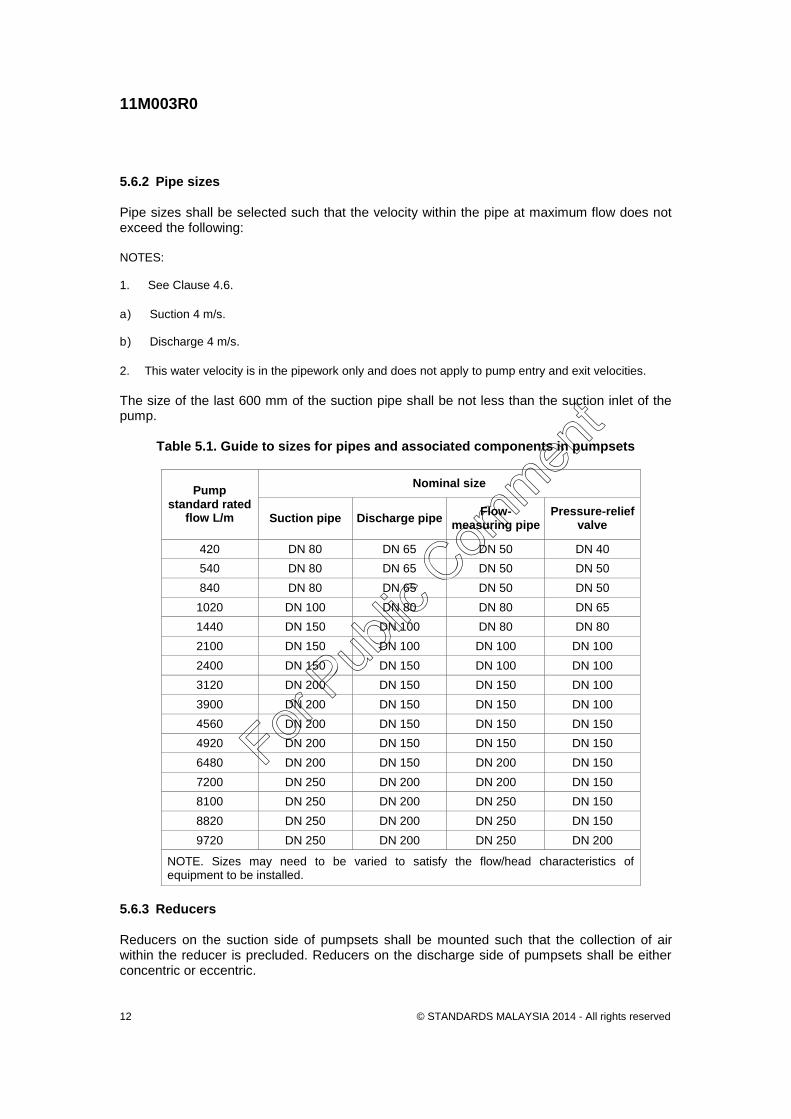
5.6.2 Pipe sizes Pipe sizes shall be selected such that the velocity within the pipe at maximum flow does not exceed the following: NOTES: 1. See Clause 4.6.
a) Suction 4 m/s.
b) Discharge 4 m/s.
2. This water velocity is in the pipework only and does not apply to pump entry and exit velocities.
The size of the last 600 mm of the suction pipe shall be not less than the suction inlet of the pump.
Table 5.1. Guide to sizes for pipes and associated components in pumpsets
Pump standard rated
flow L/m
Nominal size
Suction pipe Discharge pipe Flow-
measuring pipe Pressure-relief
valve
420 DN 80 DN 65 DN 50 DN 40
540 DN 80 DN 65 DN 50 DN 50
840 DN 80 DN 65 DN 50 DN 50
1020 DN 100 DN 80 DN 80 DN 65
1440 DN 150 DN 100 DN 80 DN 80
2100 DN 150 DN 100 DN 100 DN 100
2400 DN 150 DN 150 DN 100 DN 100
3120 DN 200 DN 150 DN 150 DN 100
3900 DN 200 DN 150 DN 150 DN 100
4560 DN 200 DN 150 DN 150 DN 150
4920 DN 200 DN 150 DN 150 DN 150
6480 DN 200 DN 150 DN 200 DN 150
7200 DN 250 DN 200 DN 200 DN 150
8100 DN 250 DN 200 DN 250 DN 150
8820 DN 250 DN 200 DN 250 DN 150
9720 DN 250 DN 200 DN 250 DN 200
NOTE. Sizes may need to be varied to satisfy the flow/head characteristics of equipment to be installed.
5.6.3 Reducers Reducers on the suction side of pumpsets shall be mounted such that the collection of air within the reducer is precluded. Reducers on the discharge side of pumpsets shall be either concentric or eccentric.
For Pub
lic Com
ment
11M003R0
© STANDARDS MALAYSIA 2014 - All rights reserved 13
5.6.4 Flanges With the exception of pipework flanges connecting to the pump flange, pipe flanges shall comply with BS EN 1092 5.6.5 Screwed joints The threads of screwed joints shall comply with MS ISO 68-1, or other approved national or international standards. 5.6.6 Grooved or shouldered joints Grooved or shouldered joints shall be of a type listed for fire protection duty. 5.6.7 Flexible connections Flexible connections on pump suction and discharge piping shall be of mechanical grooved coupling type and rubber bellows shall not be used. 5.6.8 Support of suction and discharge piping Suction and discharge piping shall be supported on either side of the pump flanges to remove pipe loads acting on the pump casing 5.7 Valves 5.7.1 Non-return valve A non-return valve shall be installed upstream of the isolating valve in each pump discharge assembly. 5.7.2 Pump isolating valves Pump-isolating valves shall be of the multi-turn type and shall comply with the requirements of BS EN 1171 or BS 5154. They shall be installed on the outlet side adjacent to the non-return valve and on the inlet side of each pump, except that butterfly valves shall not be installed on the inlet side. Valves within 15 pipe diameters of the pump inlet shall not be of the butterfly valve type. 5.7.3 Air release valves For horizontal split casing pumps, a valve shall be installed to automatically release air from the fire protection pumps which are likely to have air entrapped within the casing or column. 5.7.4 Circulation relief valve 5.7.4.1 General Each pumpset listed in Clause 5.2.1 shall be fitted with a circulation relief valve to provide sufficient flow to protect the pump from overheating and recirculation damage when operating with no or low discharge. Provision shall be made for discharge to waste.
For Pub
lic Com
ment
11M003R0
© STANDARDS MALAYSIA 2014 - All rights reserved 14
NOTES: 1. This Clause does not apply to compression-ignition engine-driven pumps where engine cooling
water is taken from the pump discharge, provided the flow through the heat exchanger satisfies the pump manufacturer's minimum flow specification.
2. When a pump is operating and discharging only through the circulation-relief valve, the temperature increase of the discharged water should not be greater than 15 °C above the pump inlet water temperature.
5.7.4.2 Sizing of circulation relief valve The circulation relief valve shall be as follows: a) hydraulically operated; b) direct-acting spring-loaded; or c) of the solenoid-controlled type. The size of the circulation-relief valve shall be 19 mm for a duty flow rate of up to 9500 L/min and 25 mm for a duty flow from 9501 L/min up to 19 000 L/min. For higher duty flow rates or high pressure pumps and vertical turbine pumps, the circulation-relief valve sizing shall be determined from the manufacturer's specified minimum flow requirements through the pump. 5.7.4.3 Pressure setting The pressure setting for the circulation relief valve shall be below the shut-off pressure at minimum expected suction pressure. 5.7.5 Pressure-relief valves 5.7.5.1 General Where required, pumpset shall be fitted with a modulating relief valve to prevent excess pressure on the system. The pressure-relief valve shall be sized to dump the flow the pumpset can produce at maximum system working pressure with the power available. The sizing of the pressure relief valve and its associated pipework shall be determined from the manufacturer's specified maximum flow rate. Where the pump is supplied from a town main, or other pressurized supply, this additional pressure shall be taken into account when determining the quantity of water to be passed by the pressure relief/flow control valve. 5.7.5.2 Valve type The pressure-relief valve shall be of the hydraulically operated, pilot-controlled type. Pressure-relief valves of the direct-acting spring-loaded type are not permitted. Backpressure shall not affect the set point of the valve. Each valve shall be actuated by line pressure through the pilot-control system. Each main valve shall open quickly to maintain a steady system pressure, then close gradually to control surges, and reseat drip tight within ±5 % of its pressure setting. External packing glands shall not be fitted.
For Pub
lic Com
ment
11M003R0
© STANDARDS MALAYSIA 2014 - All rights reserved 15
The construction of the valve shall be such that the internal components can be inspected without dismantling the pipework. NOTE. A typical pilot-control valve would take the form of a direct-acting, adjustable, spring-loaded diaphragm valve designed for modulating service to permit flow when the controlling pressure exceeds the spring setting.
5.7.5.3 Pressure setting The pressure-relief valve shall be set to prevent the maximum system working pressure being exceeded. 5.7.5.4 Location Where fitted, pressure-relief valves shall be installed on piping taken off between the pump discharge flange and any discharge non-return or isolating valve. Isolation valves shall not be fitted upstream or downstream of pressure-relief valves. 5.7.5.5 Discharge Where multiple pressure-relief valves are installed, they shall not be manifolded. Each pressure-relief valve shall have its own discharge to waste or water source, independent of flow-measuring discharge piping. Discharge from the pressure-relief valve shall not be returned to the pump suction pipe. If the discharge cannot be returned to the water source, it may be taken to waste. The return to the water source shall be sized so that the backpressure on the valve does not exceed the pressure setting determined in accordance with Clause 5.7.5.3. Where discharge from a pressure-relief valve is returned to a reservoir, it shall enter at a point remote from the pump suction at a horizontal distance of 5 m away and with the pipe extending 1 m below the normal water line. 5.8 Visibility of discharge A flow indicator shall be fitted, except where discharge from pressure-relief valves and circulation-relief valves is visible to the operator when at the pumpset. 5.9 Pressure Gauges 5.9.1 General Pressure gauges shall comply with BS 1780, and have a dial not less than 100 mm in diameter and be graduated in bars or kilopascals. 5.9.2 Discharge pressure gauge A pressure gauge shall be connected to the pump discharge together with a gauge cock. The gauge shall measure pressure to at least twice the rated pressure of the pump but not less than 1000 kPa.
For Pub
lic Com
ment
11M003R0
© STANDARDS MALAYSIA 2014 - All rights reserved 16
The discharge pressure gauge shall be as follows: a) located in a section of pipe complying with Clause 5.6.2;
b) located at least two diameters downstream of the discharge flange or end of
divergence; and
c) located at least one diameter upstream of any bends or divergences in the discharge piping.
5.9.3 Suction pressure gauge A compound pressure and vacuum gauge shall be connected to the pump suction together with a gauge cock. The suction pressure gauge shall as follows: a) be located in a section of pipe complying with Clause 5.6.2;
b) be located at least two diameters upstream of the pump flange inlet or divergence; and
c) have two diameters of straight pipe upstream following a sudden contraction, bend,
valve or other discontinuity of cross sectional area. If gauges are installed in the inlet and outlet flanges of the pump, then it shall be recognized that the algebraic sum of the two gauge readings adjusted to pump datum and after allowance for velocity head at the gauge point, may not be a true indication of the head generated by the pump due to turbulence. 5.10 Flow measuring devices 5.10.1 General Each pump type listed in Clause 5.2.1 shall incorporate means for measuring rate of flow. The flow control valve shall be located downstream of the flow-measuring device. NOTES: 1 Meters, manometers and similar instruments need not be permanently installed. 2 The flow control valve should be a globe valve.
For multiple pump installations, each pump shall have an independent flow measurement connection complete with isolating valve installed between the pump non-return valve and the pump discharge isolating valve and shall be arranged as shown in Figure 5.4. 5.10.2 Capacity The flow-measuring device and pipework shall be capable of measuring a flow of not less than 110 % of pump maximum flow. When more than one pump is required to satisfy the system demand, the flow-measuring device and pipework shall also be capable of measuring not less than 110 % of the maximum required combined flow. The inside diameter of the flow test piping shall be indicated on the pipe.
For Pub
lic Com
ment
11M003R0
© STANDARDS MALAYSIA 2014 - All rights reserved 17
5.10.3 Discharge The flow-measuring device shall not discharge into the pump suction. Where practicable, flow measurement water shall be returned to the storage tank(s). If returned to the storage tank(s), the discharge shall enter at a point remote from any pump suction. 5.11 Starting and control 5.11.1 Arrangement Fire pumpsets shall be arranged for automatic and manual starting. Except for overspeed shutdown for compression ignition drivers, stopping arrangements shall be manual only. 5.11.2 Automatic pump starting Pressure transducers may be utilized to supplement the required pressure switch(es). Refer to Appendix G for pressure switch arrangement. 5.11.3 Warning sign A warning sign, with the words `DANGER: THIS PUMP STARTS AUTOMATICALLY', shall be provided for fixing securely on each pumpset. 5.12 Electrical Requirements 5.12.1 General The electrical installation associated with fire pumpset systems shall comply with the MS IEC 60364 and MS IEC 60947 provisions intended to achieve a secure supply. When required to operate during emergency conditions, it shall not be capable of being inadvertently disconnected by the following: a) supply arrangements that maintain segregation and separation of control and
protection; and
b) wiring systems that maintain circuit integrity under-fire conditions (see Annex A). 5.12.2 Electronic component rating All semiconductors and discrete components shall be industrial grade rated and shall have an operating temperature range of 0 °C to 55 °C. 5.12.3 Alternative power supply Where an electric fire pumpset is supplied by a dedicated compression ignition generator, a separate continuous power source shall be provided for the controller.
For Pub
lic Com
ment
11M003R0
© STANDARDS MALAYSIA 2014 - All rights reserved 18
5.13 Marking 5.13.1 Method of marking Durable, corrosion-resistant identification plates shall be securely affixed in positions where they can be readily seen. Lettering on the identification plates shall be engraved or embossed 5.13.2 Pumpset An identification plate shall be affixed to the pumpset baseplate. It shall include, as a minimum, the following information: a) manufacturer's name and address;
b) duty flow;
c) duty speed;
d) duty pressure;
e) pumpset serial number;
f) maximum power required; and
g) maximum test flow.
5.13.3 Pump The identification plate shall be affixed to the pump casing. It shall include, as a minimum, the following minimum information: a) manufacturer's name and address;
b) pump serial number;
c) model or type designation;
d) number of stages; and
e) impeller diameter.
5.13.4 Driver Drivers shall be marked as follows: a) Compression-ignition engine
The identification plate shall be affixed to the engine block. It shall include, as a minimum, the following minimum information:
i) manufacturer's name;
For Pub
lic Com
ment
11M003R0
© STANDARDS MALAYSIA 2014 - All rights reserved 19
ii) model number;
iii) serial number; and
iv) rated power output and speed in accordance with ISO 3046-1.
b) Electric motor
The identification plate on an electric motor shall comply with MS IEC 60034.
5.13.5 Controller An identification plate shall be affixed to the fire pump controller cabinet. It shall include as a minimum the following: a) manufacturer's name and address;
b) identification number; and
c) electrical rating in volts, kilowatts, amperes, frequency and phases, as appropriate.
5.13.6 Battery An identification plate shall be affixed to the battery enclosure or cover. It shall include the following information as applicable: a) voltage;
b) cold cranking amperage (CCA) (compression ignition engine)
c) rated capacity in A/hr at the 20 hr rate;
d) boost absorption charge voltage;
e) float charge voltage; and
f) a warning to check the charger output before changing batteries and that the
installation of batteries not matching the information detailed on the identification plate may lead to failure of the battery(ies) including rupture or explosion of the battery(ies) casing. These failures are due to internal pressure accumulation or explosion from ignition of excessive hydrogen generation as a result of overcharging.
5.14 Pumpset Painting The pump, driver, controller and baseplate (unless galvanized) shall be painted signal red. 5.15 Pumpset Manuals Each pumpset shall be supplied with a set of manuals incorporating performance curves and relevant data, together with operating and maintenance requirements for the particular driver, pump, and controller.
For Pub
lic Com
ment
11M003R0
© STANDARDS MALAYSIA 2014 - All rights reserved 20
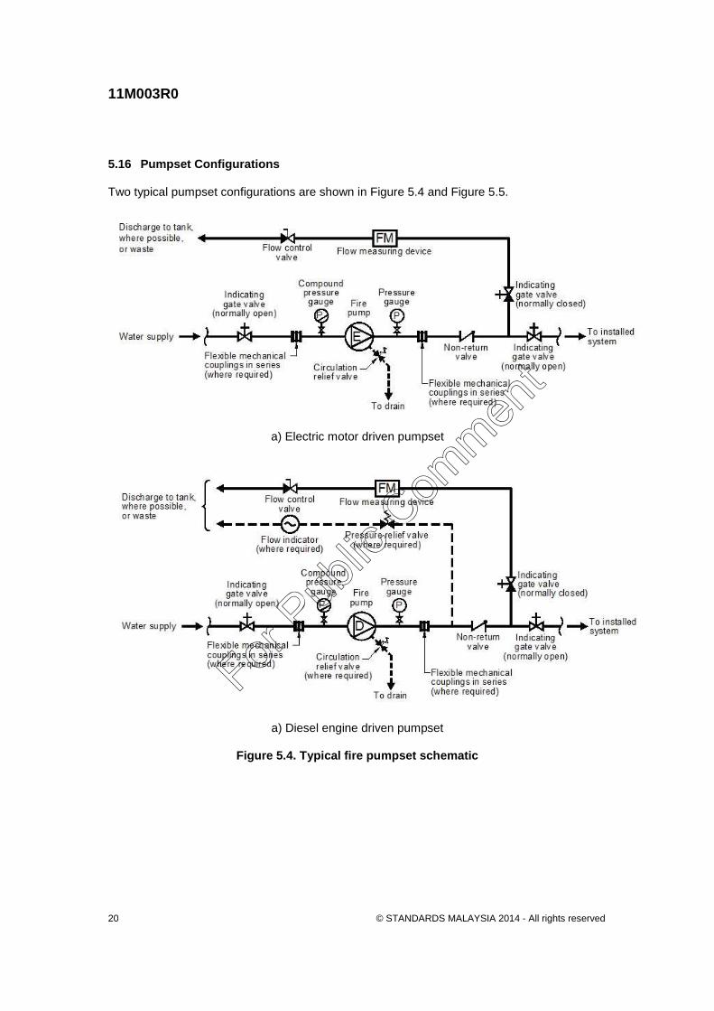
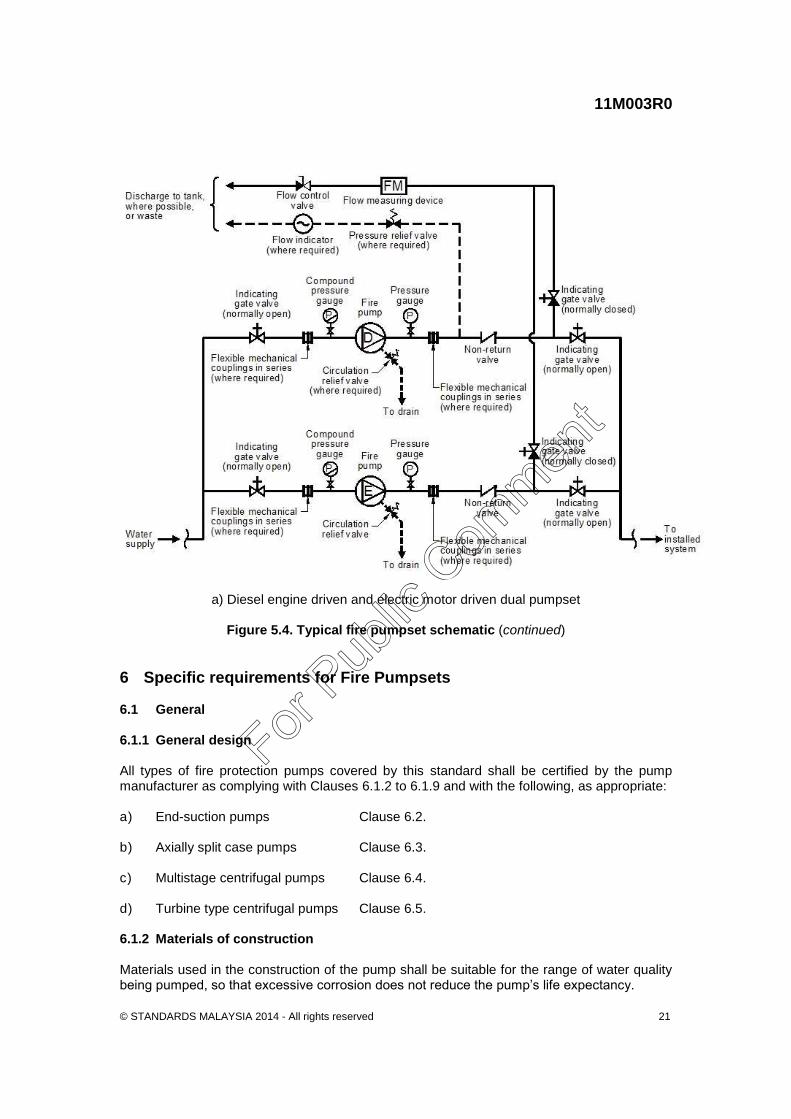
5.16 Pumpset Configurations Two typical pumpset configurations are shown in Figure 5.4 and Figure 5.5.
a) Electric motor driven pumpset
a) Diesel engine driven pumpset
Figure 5.4. Typical fire pumpset schematic
For Pub
lic Com
ment
11M003R0
© STANDARDS MALAYSIA 2014 - All rights reserved 21
a) Diesel engine driven and electric motor driven dual pumpset
Figure 5.4. Typical fire pumpset schematic (continued)
6 Specific requirements for Fire Pumpsets 6.1 General 6.1.1 General design All types of fire protection pumps covered by this standard shall be certified by the pump manufacturer as complying with Clauses 6.1.2 to 6.1.9 and with the following, as appropriate: a) End-suction pumps Clause 6.2.
b) Axially split case pumps Clause 6.3.
c) Multistage centrifugal pumps Clause 6.4.
d) Turbine type centrifugal pumps Clause 6.5. 6.1.2 Materials of construction Materials used in the construction of the pump shall be suitable for the range of water quality being pumped, so that excessive corrosion does not reduce the pump’s life expectancy.
For Pub
lic Com
ment
11M003R0
© STANDARDS MALAYSIA 2014 - All rights reserved 22
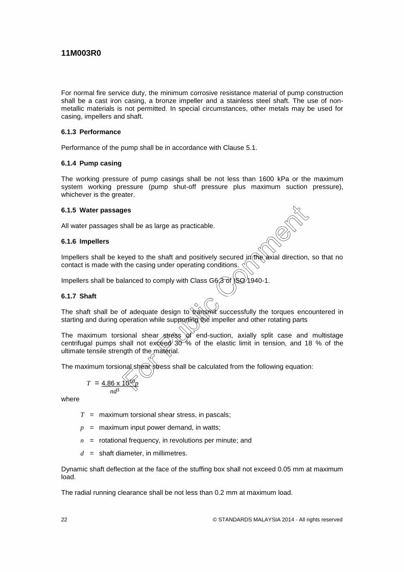
For normal fire service duty, the minimum corrosive resistance material of pump construction shall be a cast iron casing, a bronze impeller and a stainless steel shaft. The use of non-metallic materials is not permitted. In special circumstances, other metals may be used for casing, impellers and shaft. 6.1.3 Performance Performance of the pump shall be in accordance with Clause 5.1. 6.1.4 Pump casing The working pressure of pump casings shall be not less than 1600 kPa or the maximum system working pressure (pump shut-off pressure plus maximum suction pressure), whichever is the greater. 6.1.5 Water passages All water passages shall be as large as practicable. 6.1.6 Impellers Impellers shall be keyed to the shaft and positively secured in the axial direction, so that no contact is made with the casing under operating conditions. Impellers shall be balanced to comply with Class G6.3 of ISO 1940-1. 6.1.7 Shaft The shaft shall be of adequate design to transmit successfully the torques encountered in starting and during operation while supporting the impeller and other rotating parts The maximum torsional shear stress of end-suction, axially split case and multistage centrifugal pumps shall not exceed 30 % of the elastic limit in tension, and 18 % of the ultimate tensile strength of the material. The maximum torsional shear stress shall be calculated from the following equation:
T = 4.86 x 10¹⁰p nd3
where
T = maximum torsional shear stress, in pascals;
p = maximum input power demand, in watts;
n = rotational frequency, in revolutions per minute; and
d = shaft diameter, in millimetres.
Dynamic shaft deflection at the face of the stuffing box shall not exceed 0.05 mm at maximum load. The radial running clearance shall be not less than 0.2 mm at maximum load.
For Pub
lic Com
ment
11M003R0
© STANDARDS MALAYSIA 2014 - All rights reserved 23
6.1.8 Bearings Suitable anti-friction bearings shall be provided to ensure smooth low friction rotation. To provide adequate durability, anti-friction bearings shall as follows: a) have a minimum calculated life rating at shut-valve and at any other maximum load
condition of not less than 5000 h (L10) (see Note);
b) be arranged to float axially on one end;
c) be lubricated with grease or oil as appropriate;
d) where oil lubricated, be provided with a constant level oiler;
e) be provided with dust caps or other suitable means of preventing foreign matter from entering; and
f) where sealed-for-life bearings are used, be provided with separate dust caps. NOTE. L10 is a reference to bearing life as described in ISO 281.
Circlips in direct contact with the bearing shall not be used for transmitting the thrust from the shaft to the inner race of the thrust bearing. NOTE. Locknuts and lock washers are preferred.
6.1.9 Shaft seal The shaft seal shall be adequately safeguarded against air leakage into the pump when the suction pressure is below atmospheric, and prevent excessive water leakage out of the pump when suction pressure is above atmospheric. Packed glands or mechanical seals may be used. Shaft sleeves, where fitted, shall be threaded to the shaft or driven by either an independent key or an extension of the impeller key. NOTE. Seals should be selected for fire pump duty; that is, with proper attention to compatibility of mating surfaces, use of relatively clean water and intermittent pump operation.
6.1.10 Direction of rotation indication A direction arrow, indicating the direction of pump rotation, shall be clearly and permanently fixed onto the pump casing. 6.1.11 Vent, pressure gauge and drain Venting of all areas of the casing and seal chamber shall be provided. Pressure gauge tapping shall be provided in the suction and discharge nozzles. Provision for drainage at the lowest points of the casing shall be provided.
For Pub
lic Com
ment
11M003R0
© STANDARDS MALAYSIA 2014 - All rights reserved 24
6.1.12 Wear rings Where wear rings are fitted, they shall be renewable and securely locked to prevent rotation.
NOTE. An interference press fit is an acceptable means of securing a wear ring.
6.2 End suction pumps 6.2.1 General design End suction pumps shall be designed in accordance with an internationally recognized dimensional standard such as DIN 24255 and shall comply with the technical requirements of ISO 2858. Pumps meeting the dimensions of EN 733 may also be permitted, provided all other technical requirements comply with this standard. The basic design pressure of the pump shall be a gauge pressure of not less than 1600 kPa at 20 °C when made of cast iron, ductile iron, carbon steel or stainless steel. 6.2.2 Casing The design of the pump casing shall permit examination and removal of impellers and other internal parts without disturbing either suction or discharge piping. An opening shall be provided to permit all parts of the pump casing to be drained. The opening shall be threaded to receive a corrosion-resistant pipe plug. 6.2.3 Impeller The impeller shall be secured with an impeller nut threaded so as to tighten with rotation. 6.2.4 Coupling Back pull-out type pumps shall include a spacer shaft coupling. The spacer shall be sized to enable removal of the rotating assembly without disturbing either the driver or the pump casing 6.3 Axially split case pumps (horizontal or vertical shaft) 6.3.1 Casing The design of the pump casing shall permit examination and removal of impellers and other internal parts without disturbing either suction or discharge piping. An opening shall be provided to permit all parts of the pump casing to be drained. The opening shall be threaded to receive a corrosion-resistant pipe plug. A threaded hole shall be provided in the upper half casing to permit release of entrapped air. Renewable casing wear rings shall be fitted. These shall be prevented from rotating by being positively located in the bottom half of the casing. 6.3.2 Impeller The impeller shall be positively located on the shaft using shaft nuts, which shall incorporate a locking device preferably of the set-screw type.
For Pub
lic Com
ment
11M003R0
© STANDARDS MALAYSIA 2014 - All rights reserved 25
6.3.3 Shaft The shaft shall be protected against wear and erosion by renewable shaft sleeves. 6.4 Multistage centrifugal pumps 6.4.1 Performance In addition to the performance requirements of Clause 5.1, the duty flow for multi-outlet pumps shall occur separately for each outlet. 6.4.2 Casing Individual parts of the pump casing shall be accurately machined to join one to the other as required, and to maintain accurate alignment for the rotating parts. Casing may be assembled by the use of pre-stressed tie bolts. A threaded hole shall be provided in each individual casing section to permit the release of entrapped air. 6.4.3 Impellers Impellers shall be positively located on the shaft using shaft nuts which shall incorporate a locking device, preferably of the set-screw type. 6.4.4 Shaft The shaft shall be protected against wear and erosion by renewable shaft sleeves, except where mechanical seals are fitted. 6.5 Turbine type centrifugal pumps (Vertical shaft) 6.5.1 Discharge head assembly Either surface or underground discharge heads are acceptable. A direction arrow, indicating the direction of pump rotation, shall be clearly and permanently fixed into the pump discharge head assembly. 6.5.2 Bowl assembly Individual parts of the bowl assembly shall be machined to ensure that all components can be aligned. Individual bowl assemblies may be coupled together as follows: a) by tie bolts;
b) by individual bolting of each bowl to the next; and
c) by threading the bowls and screwing them together. NOTE. The method outlined in Item c) above should not be used on bowls above 200 mm nominal diameter.
For Pub
lic Com
ment
11M003R0
© STANDARDS MALAYSIA 2014 - All rights reserved 26
For oil-lubricated pumps and shafts, the discharge case shall have a seal to minimize the leakage of water into the oil tube, and shall have bypass ports of sufficient area to permit satisfactory oil leakage from the dead loss system. 6.5.3 Impellers Impellers shall be securely fastened to the impeller shaft. No impeller shall contact the bowl assembly under operating conditions. Impellers shall be of the, enclosed or semi-open type. Impellers of a diameter less than 250 mm shall be statically balanced. The pump shall be manufactured with a suitable means to adjust the vertical setting of the impeller in relation to the bowl. 6.5.4 Column pipes Column pipes shall be of adequate size and strength to withstand the forces and stresses imposed during all pump operating conditions. To facilitate maintenance and repair and where site conditions permit, column piping shall be supplied in interchangeable lengths and coordinated with line shaft bearing spacing. Column pipe connections shall be either threaded or flanged, and shall provide accurate alignment and adequate water tightness. NOTE. The maximum column diameter for threaded connections is considered to be 200 mm. For diameter greater than 200 mm, flanged joints should be used in preference to other types of joints. The size of the column should be such that the hydraulic friction loss will not exceed 5 % of the total discharge head.
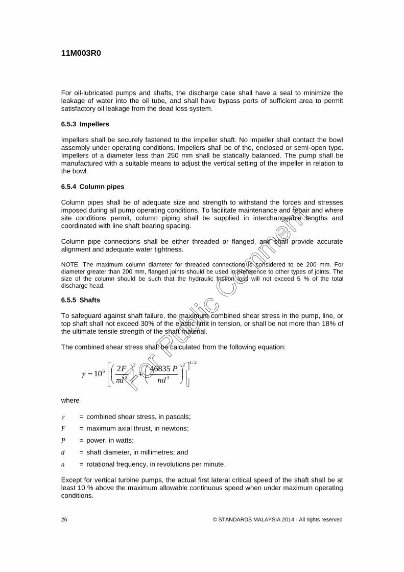
6.5.5 Shafts To safeguard against shaft failure, the maximum combined shear stress in the pump, line, or top shaft shall not exceed 30% of the elastic limit in tension, or shall be not more than 18% of the ultimate tensile strength of the shaft material. The combined shear stress shall be calculated from the following equation:
2/12
3
2
2
6 46835210
nd
P
d
F
where
= combined shear stress, in pascals;
F = maximum axial thrust, in newtons;
P = power, in watts;
d = shaft diameter, in millimetres; and
n = rotational frequency, in revolutions per minute. Except for vertical turbine pumps, the actual first lateral critical speed of the shaft shall be at least 10 % above the maximum allowable continuous speed when under maximum operating conditions.
For Pub
lic Com
ment
11M003R0
© STANDARDS MALAYSIA 2014 - All rights reserved 27
Line shafts shall be supplied in uniform lengths. NOTE. Line shafts should be made of a corrosion-resistant material.
6.5.6 Line-shaft coupling Line shafts shall be connected by threaded or keyed couplings which shall be of material similar to that of the line shaft, but selected to prevent galling. Couplings shall be designed to withstand not less than 150 % of the acceptable combined shear stress as calculated in accordance with Clause 6.5.5 (see Note 1). Threaded couplings shall have parallel threads (see Note 2). NOTES: 1 The additional strength is needed to compensate for the additional load the connecting line shafts
exert on the coupling because of its standard straight pipe thread. 2 Threaded couplings tend to tighten during pump operation. 3 Keyed couplings are recommended for line shafts above 50 mm diameter. Threaded couplings are
not recommended for line shafts exceeding 50 mm in diameter because of the difficulty in unscrewing the coupling for maintenance.
6.5.7 Line-shaft bearings Line-shaft bearings shall be as follows: a) of the open water-lubricated or enclosed oil-lubricated type;
b) protected from damage due to dry running during starting; and
c) be fitted with an automatic dead loss lubrication system, if oil-lubricated. 6.5.8 Line-shaft enclosing tube Enclosed line-shaft oil-lubricated pumps shall be furnished with a shaft enclosing tube of heavy pipe (Schedule 80 or heavier) in sections. The shaft enclosing tube shall be capable of being tensioned to minimize misalignment of bearings. It shall be adequately supported within the column. 6.5.9 Oil lubrication system The oil lubrication system shall be automatic and shall be capable of operating for a minimum of 6 h. The oil lubrication system shall consist of the following: a) reservoir of 8 L minimum capacity;
b) solenoid valve (to switch oil supply on when pump is started); and
c) interconnecting tubing and fittings of 6 mm minimum ID.
For Pub
lic Com
ment
11M003R0
© STANDARDS MALAYSIA 2014 - All rights reserved 28
6.5.10 Automatic air-release valve An automatic air-release valve, of not less than 32 mm diameter, shall be provided at the highest point in the discharge line between the fire pump and the discharge non-return valve. This valve shall vent air from the column and discharge head upon starting the pump, and admit air to the column to prevent formation of a vacuum when the pump is stopped. 6.6 Drivers for vertical turbine pumps 6.6.1 Permissible types Vertical turbine pumps may be driven by one of the following: a) vertically mounted electric motor; and b) horizontally mounted electric motor or compression-ignition engine through a right-
angle gearbox.
All motors shall be directly coupled to their respective pumping units. 6.6.2 Provision for axial thrust A thrust bearing of sufficient capacity to accommodate all hydraulic and mechanical thrusts shall be incorporated in the electric driver, angle gear driver, or motor stool assembly. Pumps applying an upward thrust to the line shaft during continuous operation are not acceptable. 6.6.3 Provision for non-reversing ratchet A non-reversing ratchet shall be incorporated in the electric driver, angle gear drive, or the motor stool assembly. 6.6.4 Right-angle gear drives Right-angle gear drives shall be rated at a useable power equal to or greater than the maximum pump power requirement. Gearbox power loss shall be included when calculating power requirement of the driver. 6.7 Positive displacement pumps for fire protection applications 6.7.1 General The positive displacement pump type and model shall be suitable for the intended application. The selected pump shall be appropriate for the viscosity of the liquid being pumped, the flow rate and the pressure requirements of the system. Positive displacement pumps are typically used for injection of additives or foam concentrate and for water mist systems. 6.7.2 Materials of construction Materials used in the construction of the pump shall be suitable for the liquids being pumped (water or foam concentrate), so as to be resistant to the corrosion potential under operational conditions.
For Pub
lic Com
ment
11M003R0
© STANDARDS MALAYSIA 2014 - All rights reserved 29
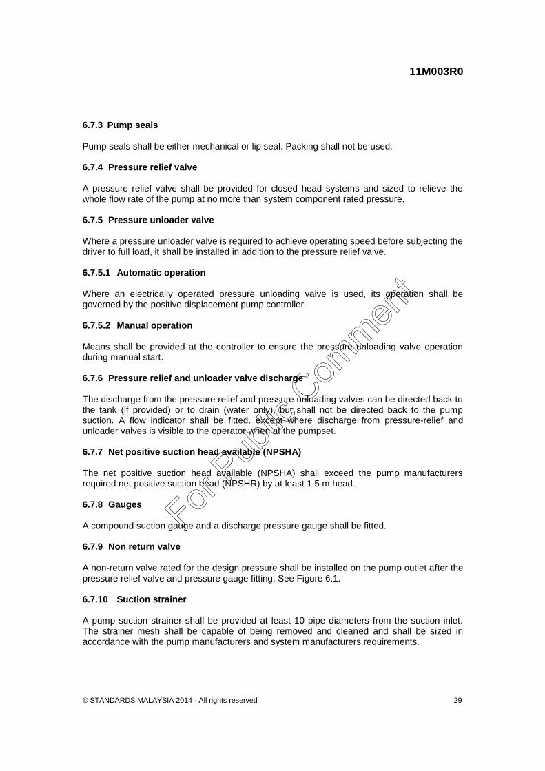
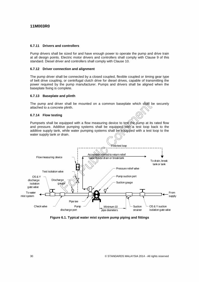
6.7.3 Pump seals Pump seals shall be either mechanical or lip seal. Packing shall not be used. 6.7.4 Pressure relief valve A pressure relief valve shall be provided for closed head systems and sized to relieve the whole flow rate of the pump at no more than system component rated pressure. 6.7.5 Pressure unloader valve Where a pressure unloader valve is required to achieve operating speed before subjecting the driver to full load, it shall be installed in addition to the pressure relief valve. 6.7.5.1 Automatic operation Where an electrically operated pressure unloading valve is used, its operation shall be governed by the positive displacement pump controller. 6.7.5.2 Manual operation Means shall be provided at the controller to ensure the pressure unloading valve operation during manual start. 6.7.6 Pressure relief and unloader valve discharge The discharge from the pressure relief and pressure unloading valves can be directed back to the tank (if provided) or to drain (water only), but shall not be directed back to the pump suction. A flow indicator shall be fitted, except where discharge from pressure-relief and unloader valves is visible to the operator when at the pumpset. 6.7.7 Net positive suction head available (NPSHA) The net positive suction head available (NPSHA) shall exceed the pump manufacturers required net positive suction head (NPSHR) by at least 1.5 m head. 6.7.8 Gauges A compound suction gauge and a discharge pressure gauge shall be fitted. 6.7.9 Non return valve A non-return valve rated for the design pressure shall be installed on the pump outlet after the pressure relief valve and pressure gauge fitting. See Figure 6.1. 6.7.10 Suction strainer A pump suction strainer shall be provided at least 10 pipe diameters from the suction inlet. The strainer mesh shall be capable of being removed and cleaned and shall be sized in accordance with the pump manufacturers and system manufacturers requirements.
For Pub
lic Com
ment
11M003R0
© STANDARDS MALAYSIA 2014 - All rights reserved 30
6.7.11 Drivers and controllers Pump drivers shall be sized for and have enough power to operate the pump and drive train at all design points. Electric motor drivers and controllers shall comply with Clause 9 of this standard. Diesel driver and controllers shall comply with Clause 10. 6.7.12 Driver connection and alignment The pump driver shall be connected by a closed coupled, flexible coupled or timing gear type of belt drive coupling, or centrifugal clutch drive for diesel drives, capable of transmitting the power required by the pump manufacturer. Pumps and drivers shall be aligned when the baseplate fixing is complete. 6.7.13 Baseplate and plinth The pump and driver shall be mounted on a common baseplate which shall be securely attached to a concrete plinth. 6.7.14 Flow testing Pumpsets shall be equipped with a flow measuring device to test the pump at its rated flow and pressure. Additive pumping systems shall be equipped with a test loop back to the additive supply tank, while water pumping systems shall be equipped with a test loop to the water supply tank or drain.
Minimum 10
pipe diameters
Suction
strainer
OS & Y suction
isolation gate valve
From
supply
Check valve
To water
mist system
Pump
discharge port
Pipe tee
Discharge
gauge
OS & Y
discharge
isolation
gate valve
Test isolation valve
Flow measuring device
Suction gauge
Pump suction port
Pressure relief valve
Acceptable method to return relief
valve flow to drain or break tank
Flow test loop
To drain, break
tank or tank
Figure 6.1. Typical water mist system pump piping and fittings
For Pub
lic Com
ment
11M003R0
© STANDARDS MALAYSIA 2014 - All rights reserved 31
7 Requirements for Pressure Maintenance Pumps 7.1 General Jockey pumps are used when it is desirable to maintain a uniform or relatively high pressure on fire protection system water mains. Uniform mains pressure is required if pressure-responsive devices are used for initiating automatic starting of pumps. Relatively high pressures may be required to permit effective fire protection system operation, pending automatic pump start. 7.2 General requirements for jockey pumps The following general requirements apply to jockey pumps: a) The rated capacities of jockey pumps shall be not less than any normal leakage rate.
The discharge pressure shall be sufficient to maintain the desired fire protection system standing pressure.
b) Jockey pumps shall be sized to make up the allowable leakage within 10min at a rate of
flow not exceeding 10 L/min. c) Jockey pumps shall be fitted with an automatic device to prevent cycling effects due to
minor system leakage. The pump shall be capable of starting at least 10 times in an hour.
d) A non-return valve shall be installed in the discharge pipe. e) Lockable isolating valves shall be installed in such places as are needed to make the
pump non-return valve and other miscellaneous fittings accessible for repair. f) If a jockey pump has a shut-off pressure exceeding the working pressure rating of the
fire protection equipment, a suitable relief valve shall be installed on the pump discharge to prevent damage to the fire protection system or the pump.
g) The jockey pump shall have its own enclosed controller that includes the following:
i) an isolating switch capable of being locked in the ‘on’ position;
ii) automatic/manual (spring return to automatic) selector switch;
iii) power ‘on’ light indicator;
iv) start contactor with thermal overload;
v) pump run and pump overload indicating lights;
vi) control circuit breaker; and
vii) a start counter (non-resettable).
h) The jockey pump controller shall be directly connected to a power supply that is independent of the fire pump circuit.
For Pub
lic Com
ment
11M003R0
© STANDARDS MALAYSIA 2014 - All rights reserved 32
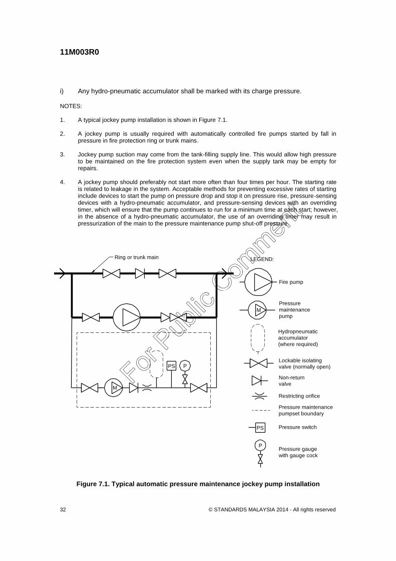
i) Any hydro-pneumatic accumulator shall be marked with its charge pressure. NOTES: 1. A typical jockey pump installation is shown in Figure 7.1. 2. A jockey pump is usually required with automatically controlled fire pumps started by fall in
pressure in fire protection ring or trunk mains. 3. Jockey pump suction may come from the tank-filling supply line. This would allow high pressure
to be maintained on the fire protection system even when the supply tank may be empty for repairs.
4. A jockey pump should preferably not start more often than four times per hour. The starting rate
is related to leakage in the system. Acceptable methods for preventing excessive rates of starting include devices to start the pump on pressure drop and stop it on pressure rise, pressure-sensing devices with a hydro-pneumatic accumulator, and pressure-sensing devices with an overriding timer, which will ensure that the pump continues to run for a minimum time at each start; however, in the absence of a hydro-pneumatic accumulator, the use of an overriding timer may result in pressurization of the main to the pressure maintenance pump shut-off pressure.
Ring or trunk main
Pressure switch
Pressure gauge
with gauge cock
LEGEND:
Pressure
maintenance
pump
Non-return
valve
Lockable isolating
valve (normally open)
Fire pump
Restricting orifice
Hydropneumatic
accumulator
(where required)
M
M
Pressure maintenance
pumpset boundary
PS P
P
PS
Figure 7.1. Typical automatic pressure maintenance jockey pump installation
For Pub
lic Com
ment
11M003R0
© STANDARDS MALAYSIA 2014 - All rights reserved 33
8 Hose Reel Pumpsets 8.1 General This clause specifies the requirements for fire hose reel pumpsets. Fire hose reel pumpsets shall comprise the following: a) a common base;
b) pump and driver;
c) valves;
d) unions;
e) piping and fittings;
f) wiring;
g) pressure gauge;
h) pressure switch; and
i) controller 8.2 Electric motor driven fire hose reel pumpsets The controller shall include the following: a) an isolating switch;
b) automatic/manual selector switch;
c) power ‘on’ light indicator;
d) start contactor with thermal overload;
e) pump run and pump fail indicating lights; and
f) control circuit breaker. 8.3 Compression ignition driven fire hose reel pumpsets Where compression-ignition drivers are used for the hose reel pumpset the pumpsets shall incorporate the following: a) Emergency manual starting and stopping facilities in addition to automatic start and
manual stop. b) Single AGM battery. c) Fuel filter/sludge and sediment trap.
For Pub
lic Com
ment
11M003R0
© STANDARDS MALAYSIA 2014 - All rights reserved 34
d) Fuel tank with a minimum 4 h fuel capacity. e) Controller incorporating the following:
i) main isolating switch;
ii) battery charger; and
iii) lights for power supply to pump controller present, pump running, pump fail and
battery charger fail; and
8.4 Type The fire hose reel pump and motor shall be close-coupled and pumps shall be centrifugal single stage or multistage pumps. 8.5 Operation Fire hose reel pumpsets shall be automatically started and stopped. They shall comply with the performance requirements of MS 1489-1. Fire hose reel pumpsets shall be so arranged as to prevent excessive cycling effects due to single hose reel operation. The pump driver shall be capable of starting at least 10 start/stops in an hour. 8.6 Electrical Wiring Wiring shall comply with the requirements of Clause 5.12. 8.7 Valves The following valves shall be provided as follows: a) non-return valve;
b) inlet isolating valve (locked in the open position);
c) outlet isolating valve (locked in the open position); and
d) Test outlet valve (locked in the closed position, discharge visible). The above valves shall be not less than DN 25. 8.8 Unions Unions shall be provided downstream of the inlet valve and upstream of the outlet valve to permit servicing of the pumpset. 8.9 Maximum Allowable Working Pressure The maximum allowable working pressure of a hose reel pumpset shall be based on the component having the lowest pressure rating, and shall exceed the sum of the maximum supply and pump shut-off pressures.
For Pub
lic Com
ment
11M003R0
© STANDARDS MALAYSIA 2014 - All rights reserved 35
8.10 Marking The identification plate shall be affixed to the pumpset baseplate. It shall bear the following minimum information: a) manufacturer’s name and address;
b) duty flow and pressure; and
c) Maximum allowable working pressure. Where compression-ignition drivers are used, the controller shall be labelled with the engine duty speed, normal oil pressure and normal engine temperature.
9 Electric drivers and controllers 9.1 Electric drivers 9.1.1 General All electric drivers shall be as follows: a) certified by the motor manufacturer or his agent as complying with the relevant
requirements of Clause 9.1.3; b) of the caged rotor induction type complying with the relevant parts of MS IEC 60034;
and c) have a degree of protection not inferior to IP54 in accordance with MS IEC 60529.
9.1.2 Types of wiring Wiring shall comply with Clause 5.12 with regards to the following: a) dedicated circuit from main switchboard for each electric driver and controller; and b) wiring system to provide WS5X classification or be installed in an enclosure or location
that provides equivalent protection, e.g. underground wiring.
NOTE. It is strongly recommended that all external wiring be installed underground.
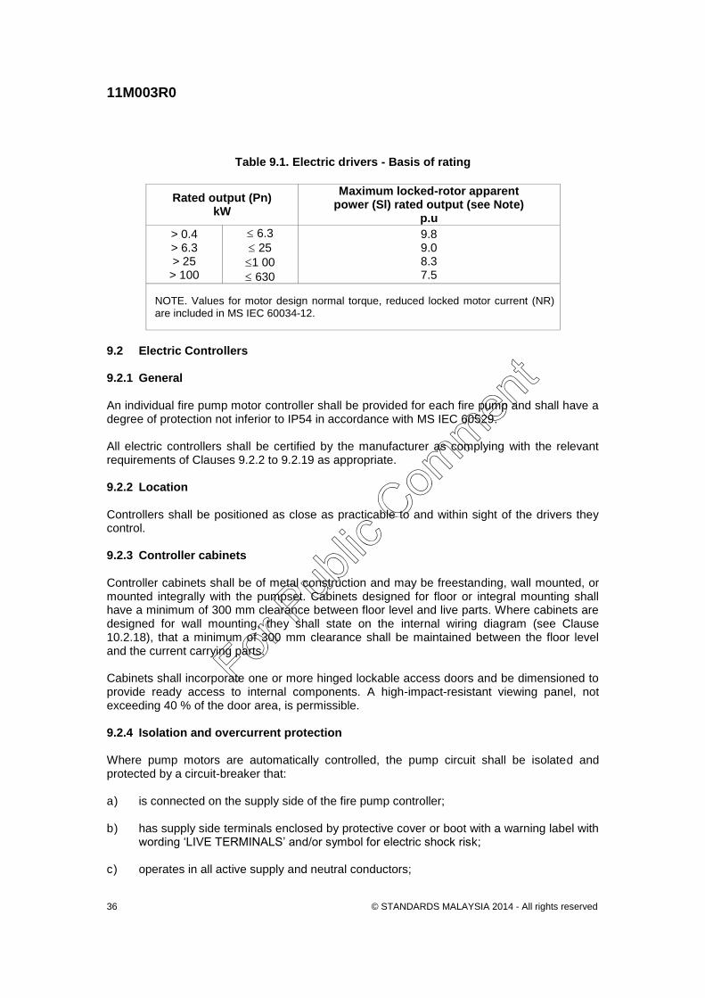
9.1.3 Basis of rating Electric motors shall be of S1 duty rating for maximum continuous rating (MCR) and of voltage rating to suit the supply voltage. The power rating of the motor shall be not less than 115 % of the power required to achieve all flows from shut-off to the maximum flow point. Motors used at altitudes above 1000 m shall have reduced temperature rises as specified in MS IEC 60072-1, MS IEC 60072-2 and IEC 60072-3. When measured at rated voltage, the locked-rotor apparent power of the motor (S1) in kilovolt amperes, expressed as per unit (p.u.) value of the rated output (Pn) in kilowatts, shall not exceed the appropriate value set out in Table 9.1.
For Pub
lic Com
ment
11M003R0
© STANDARDS MALAYSIA 2014 - All rights reserved 36
Table 9.1. Electric drivers - Basis of rating
Rated output (Pn) kW
Maximum locked-rotor apparent power (Sl) rated output (see Note)
p.u
> 0.4 > 6.3 > 25 > 100
6.3
25
1 00
630
9.8 9.0 8.3 7.5
NOTE. Values for motor design normal torque, reduced locked motor current (NR) are included in MS IEC 60034-12.
9.2 Electric Controllers 9.2.1 General An individual fire pump motor controller shall be provided for each fire pump and shall have a degree of protection not inferior to IP54 in accordance with MS IEC 60529. All electric controllers shall be certified by the manufacturer as complying with the relevant requirements of Clauses 9.2.2 to 9.2.19 as appropriate. 9.2.2 Location Controllers shall be positioned as close as practicable to and within sight of the drivers they control. 9.2.3 Controller cabinets Controller cabinets shall be of metal construction and may be freestanding, wall mounted, or mounted integrally with the pumpset. Cabinets designed for floor or integral mounting shall have a minimum of 300 mm clearance between floor level and live parts. Where cabinets are designed for wall mounting, they shall state on the internal wiring diagram (see Clause 10.2.18), that a minimum of 300 mm clearance shall be maintained between the floor level and the current carrying parts. Cabinets shall incorporate one or more hinged lockable access doors and be dimensioned to provide ready access to internal components. A high-impact-resistant viewing panel, not exceeding 40 % of the door area, is permissible. 9.2.4 Isolation and overcurrent protection Where pump motors are automatically controlled, the pump circuit shall be isolated and protected by a circuit-breaker that: a) is connected on the supply side of the fire pump controller;
b) has supply side terminals enclosed by protective cover or boot with a warning label with
wording ‘LIVE TERMINALS’ and/or symbol for electric shock risk;
c) operates in all active supply and neutral conductors;
For Pub
lic Com
ment
11M003R0
© STANDARDS MALAYSIA 2014 - All rights reserved 37
d) provides the overcurrent protection characteristics for fire pumps; and
e) is capable of being locked in the ‘on’ position (power supply on).
NOTE. High efficiency motors may require 7 to 8 times the full load current (FLC) holding capacity for the circuit breaker.
9.2.5 Motor starter The motor starter shall comply with the appropriate requirements of MS IEC 60947-2, MS IEC 60947-4-1, or MS IEC 60947-4-2, as applicable. The thermal overload relay shall not be connected to trip the starter. NOTE. The thermal overload relay may be omitted from the motor starter or it may be used to provide a visual or aural indication that the motor has exceeded its thermal rating.
The transition through the starting steps shall be automatic (that is, independent of an operator). The motor shall attain full speed within 15 s of receipt of start signal. The starters shall be rated for intermittent duty Class 0.1. NOTE. This does not preclude the use of soft start and frequency inverter type motor starters.
9.2.6 Variable speed control Where a variable speed pressure-limiting control is fitted on an electric driver the variable speed control shall be capable of limiting pump discharge pressure to 110 % of duty head (pressure) by reducing pump speed. In the event of failure of the variable speed control, the driver shall continue to operate at duty speed. Where a variable speed pressure limiting control is fitted on an electric driver, a pressure-relief valve shall also be installed on the pump discharge. 9.2.7 Equipment segregation 9.2.7.1 Low and extra-low voltage components Low and extra-low voltage components, associated wiring and terminal strips shall be segregated within the fire pump controller in accordance with the following provisions: a) low and extra-low voltage equipment shall be placed in a separate compartment or
enclosure; or b) common compartment or enclosure of low and extra-low voltage equipment provided
that: i) low voltage wiring systems provide double insulation or extra-low voltage wiring
systems are insulated to low voltage; and
ii) terminations of the low voltage and extra-low voltage wiring systems are effectively separated.
For Pub
lic Com
ment
11M003R0
© STANDARDS MALAYSIA 2014 - All rights reserved 38
NOTES : 1. ‘Extra-low voltage’ is defined as not exceeding 50V a.c. or 120V ripple free d.c.
2. ‘Low voltage’ is defined as exceeding extra-low voltage but not exceeding 1000V a.c. or 1500V d.c.
9.2.7.2 Mixed voltage components Mixed voltage (e.g. 240 V a.c./24 V d.c.) components shall be located in the compartment provided for the higher voltage, and shall be labelled accordingly. 9.2.8 Control devices The alarm power supply battery shall not be used or interfere with automatic or manual pump start and running. In addition to the isolating switch, the fire pump controller shall have externally operable manual stop and start switches. The operation of the manual stop switch shall automatically return the fire pump controller to the automatic start position. The operation of the manual start switch shall override any automatic start facilities. Touch screens shall not be used for primary operation - start, stop and reset.
9.2.9 Indicator lights Indicator lights shall be of the filament, neon, LCD, Plasma or (LED) types. If filament lights are used, they shall be either twin metal filament type or two individual lights, and the voltage applied shall not exceed 80 % of the rated voltage of the lights. All lights shall be accessible for replacement. LCD, plasma or other displays may be used instead of indicator lights. Where used, LCD, Plasma or other displays shall be of robust design and large screen to show all required information on the screen at once. They shall also be protected from direct sunlight. Where an LCD or plasma or other displays are utilized, the following requirements apply: a) LED backlighting shall be used in the case of LCD; b) the device shall have a specified operating temperature range that includes the entire
expected range of temperatures that the device will experience in service and as a minimum will include 0 to 55 °C; and
c) the specified operational life shall exceed 50,000 hours of continuous usage.
The following indicators shall be provided, and shall be permanently displayed and colour-coded as specified: i) Power On (Power supply to pump present (all phases) green.
ii) Power Fail (Phase failure or phase rotation incorrect red.
iii) Pump running (alarm condition) red.
For Pub
lic Com
ment
11M003R0
© STANDARDS MALAYSIA 2014 - All rights reserved 39
iv) Battery charger supply failure red.
v) Variable speed control malfunction, if applicable red.
vi) Aural alarm silenced red. 9.2.10 Remote alarm contacts The controller shall incorporate volt-free contacts for ‘power supply to pump present (all phases)’, ‘pump running’ and ‘pump common fault alarm’. The ‘pump common fault alarm’ may denote phase failure, phase rotation incorrect, battery charger supply failure, variable speed control malfunction or aural alarm silenced (see Clause 9.2.9). 9.2.11 Aural alarms An aural alarm, integral with the fire pump controller, shall be provided and protected against an overcurrent of 150 %. If a remote aural alarm is provided, the integral alarm may be omitted. Controller should be equipped to operate circuits for remote indication for the following conditions: a) the power or a phase is loss and reversed phase;
b) the motor is running; and
c) the controlled main switch have been turned to the off of manual position The aural alarm shall operate simultaneously with the lights indicating power supply failure, phase failure, and pump running (alarm condition) indications.
NOTE. The aural alarm should reset after power restoration.
The sound level output shall exceed normal background levels by not less than 10 dBA, but shall be not less than 65 dBA and not more than 105 dBA.
NOTE. A suitable location for the aural alarm may be at a manned plant gatehouse or control centre.
9.2.12 Alarm power supply The power supply for the indicator lights and alarms shall be taken from a monitor battery complying with Clause 9.2.16. 9.2.13 Test facility A test facility shall be provided for the testing of indicator lights and audible alarms. 9.2.14 Ammeter An ammeter shall be provided on the face of the fire pump controller cabinet to indicate selectively the phase currents of the motor.
For Pub
lic Com
ment
11M003R0
© STANDARDS MALAYSIA 2014 - All rights reserved 40
9.2.15 Conductor terminations Conductor terminations shall be achieved in the following ways: a) control conductors shall utilize numbered tunnel type terminal blocks incorporating
studs or screws for both internal and outgoing conductors; b) conductors shall be correspondingly numbered and provided with compatible terminals.
The shanks of the terminals shall be insulated; c) conductors shall be of sufficient length to allow a fresh termination to be made should
the original break off; d) conductors rated under 100 A shall be terminated using screwed clamp type terminals
or swaged termination that are bolted; e) conductors rated at 100 A or greater shall be terminated with swaged terminations that
are bolted; and f) conductors shall be grouped together and laced neatly. 9.2.16 Monitor battery The battery shall be installed on a frame with the battery base at least 150 mm above the floor, and the terminals shall be protected by a non-conductive material either by battery cover or terminal boots. Where the battery is housed in a separate enclosure, the enclosure shall be ventilated. The battery shall not be installed within the fire pump controller and shall comply with the following: a) service life shall be rated at not less than 2 years; b) the battery capacity shall be sufficient to maintain the monitoring and alarm functions of
the electric controller for 72 h; and c) sealed batteries (VRLA) shall be of the Absorbed Glass Matt (AGM) type.
NOTE. Either vented ‘stationary’ or sealed ‘VRLA’ batteries can be provided.
The battery shall be identified by a plate, attached to or adjacent to the battery enclosure or cover, in accordance with the requirements of Clause 5.13.6. 9.2.17 Battery chargers A battery charger shall be provided to service the monitor battery. The battery charger together with the associated ammeter and voltmeter, shall be incorporated into the fire pump controller cabinet. The accuracy tolerance of both the ammeter and voltmeter shall be 5 % across the whole range. The battery charger shall be capable of three stage battery charging consisting of boost, absorption and float stages.
For Pub
lic Com
ment
11M003R0
© STANDARDS MALAYSIA 2014 - All rights reserved 41
9.2.18 Wiring diagrams A complete set of wiring diagrams, including that for the driver, shall be provided and permanently attached to the inside of the enclosure and protected by a transparent durable cover. The diagrams shall be numbered to coincide with fire pump controller terminals. 9.2.19 Marking Each driver control device and each switch and circuit-breaker shall be marked to indicate plainly the name of the manufacturer, model number, and applicable electrical rating. All fire pump controller cabinets shall be marked ‘ELECTRIC FIRE PUMP CONTROLLER’ and show the name of the manufacturer, and the manufacturer’s model designation. All indicating lights, switches, and meters shall be provided with designating, permanently secured/fixed labels. 9.2.20 Pre-delivery testing Controllers shall be completely assembled, wired, bench-tested and certified by the manufacturer before dispatch.
10 Compression ignition drivers and controllers 10.1 Driver type The driver shall be certified by the manufacturer as complying with Clauses 10.1 and 10.2 and the relevant parts of Clause 10.3. The driver shall as follows: a) be of the liquid-cooled or air-cooled compression-ignition type; b) capable of being started without the use of wicks, cartridges, heater plugs or other
starting devices; c) have a degree of protection not inferior to IP23 in accordance with MS IEC 60529; and d) be fitted with thermostatically controlled jacket or block heating equipment to keep the
temperature 45 to 49°C.
Fuel lines on the engine shall comply with the requirements of Item 10.3.3.3(d) and (e). The driver may be electronically controlled. NOTES: 1 Particular care should be taken to ensure that sufficient cooling airflow is available. 2 Jacket or block heating uses a 240 V power source. A warning sign should be provided advising of
its presence.
For Pub
lic Com
ment
11M003R0
© STANDARDS MALAYSIA 2014 - All rights reserved 42
10.2 Driver performance 10.2.1 Fuel The driver shall be designed to operate on fuels complying with the requirements of AS 3570 for Class No.2D. NOTE. Bio-diesel and other alternative fuels are not recommended for diesel engines used for fire protection because of the unknown storage life issues.
10.2.2 Engine power The engine power shall be the ‘Fuel Stop Power’ as defined in ISO 15550 (see Note). The engine power at the governed speed shall be not less than 115 % of the power required to achieve all flows from shut-off to maximum flow point. The engine power for the specific site shall be determined by adjusting for elevation by deducting 3 % from the engine power for every 300m above 90m ASL (above sea level), and ambient temperature by deducting 1 % from the engine power for every 5.6 above 25 °C. NOTE. ‘Fuel Stop Power’ is defined in ISO 15550 as ‘power which an engine is capable of delivering during a stated period corresponding to its application, and stated speed and under stated ambient conditions, with the fuel limited so that this power cannot be exceeded’.
10.2.3 Service life Compression-ignition fire pump drivers are expected to perform reliably under normal application conditions for a minimum of 2000 h between overhauls or 5 years, whichever comes first. 10.2.4 Starting capability The driver shall be capable of starting from cold and accelerating to full speed within 15 s of the cranking cycle being initiated under all extremes of site conditions. NOTE. For ambient temperature, see Clause 12.2.
10.3 Driver systems 10.3.1 Lubrication system Drivers shall be equipped with a suitable pressure-type lubrication system. The system shall comprise a direct engine-driven pump, a filter and distribution system. Drivers shall have adequate capacity to maintain lubricant temperatures within the range recommended by the lubricant manufacturer. The lubrication filter medium shall be readily replaceable or the filter shall be of the type allowing ready cleaning. Accessible means shall be provided for checking, draining, and replenishing the lubricant supply.
For Pub
lic Com
ment
11M003R0
© STANDARDS MALAYSIA 2014 - All rights reserved 43
10.3.2 Cooling system 10.3.2.1 General The manufacturer shall state the desirable operating temperature range for the driver. The primary cooling system shall automatically maintain the driver within the desirable operating temperature range. Vee-belt drives forming part of the cooling system shall incorporate multiple belts so that if half the belts break, the remaining belts shall be capable of performing the drive functions. A single automatically tensioned multiple-rib belt with no less than 4 ribs, may be used in lieu of multiple vee-belts. 10.3.2.2 Liquid cooling systems Liquid cooling systems shall have a closed primary loop. The heat from the primary loop may be dissipated either directly to the atmosphere or to a secondary open, raw water cooling circuit. Liquid cooling systems shall be provided with an opening in the primary loop for replenishing the coolant or checking the liquid level. An expansion reservoir shall also be provided to minimize loss of coolant due to thermal expansion and contraction. Flexible hoses in accordance with the engine manufacturer’s minimum specifications shall be of the reinforced type and shall be securely clamped to ribbed or beaded tails. NOTE. Barbed hose tails should not be used.
Where the primary coolant heat is dissipated directly to the atmosphere, an engine-driven fan shall be provided for positive movement of air through the heat exchanger (radiator). Sufficient natural ventilation to comply with the engine manufacturer’s requirements shall be provided. The system shall be designed to maintain normal engine operating temperature, with an inlet air temperature of 50 °C. NOTE. For ventilation, see Clause 12.5.
Where a raw water secondary coolant is used, the flow and pressure of the raw water shall be such that the maximum operating temperature of the engine will not be exceeded at full load governed speed. The raw water outlet pipe from the heat exchanger shall be at least one pipe size larger than the inlet. The main heat exchanger raw water cooling line shall include a strainer, pressure reducing (regulating) valve, automatic actuating valve and indicating isolating valves. The bypass heat exchanger raw water cooling water line shall have a strainer, pressure reducing valve and indicating isolating valves. A pressure gauge shall be provided prior to the heat exchanger inlet piping connection. The outlet pipe from the heat exchanger shall be arranged so that the discharge is visible. NOTE. Where the automatic actuating valve is dependent on differential pressure to operate, care should be taken to ensure the pump differential pressure is substantially greater than that required to operate the valve, otherwise a solenoid valve should be used.
Throttling valves or fixed orifices shall not be used in place of pressure reducing valves. Raw water secondary cooling piping shall be corrosion protected steel. A flexible hose shall be provided at the inlet to the heat exchanger and any rigid outlet piping. The flexible hose shall be fire resistant, have a reinforcing inner braid, and a cover resistant to oil, mildew and abrasion. It shall be capable of withstanding a pressure of not less than 1000 kPa and a temperature range of -40 °C and +150 °C.
For Pub
lic Com
ment
11M003R0
© STANDARDS MALAYSIA 2014 - All rights reserved 44
NOTE. Hose meeting these requirements when tested in accordance with ISO 15540 and listed by organizations such as ABS (American Bureau of Shipping) and Det Norske Veritas, are acceptable.
Each indicating isolating valve in the heat exchanger cooling system shall be locked in its normal operating position. The cooling water solenoid, where fitted, shall: a) be normally closed;
b) be energized to open on engine start; and
c) mechanically latched in the open position.
NOTE. Flow and pressure requirements for secondary coolants are usually specified by the engine manufacturer.
10.3.2.3 Air-cooling systems Air-cooling systems shall provide an engine-driven fan and a connection to discharge coolant exhaust air outside the pump room. Sufficient natural ventilation to comply with the engine manufacturer’s requirements shall be provided. The system shall be designed to maintain normal engine operating temperature, with an inlet air temperature of 50 °C (see Clause 12.5). 10.3.2.4 Supplementary cooling systems Supplementary cooling devices, such as lubricant and inlet air coolers, may be used, provided they share raw water or coolant air supplies with the primary engine-cooling systems specified in Clause 10.3.2.3. 10.3.2 Fuel system 10.3.3.1 Electronic fuel management system Where the driver incorporates electronic fuel management, a single electronic control module (ECM) may be used to control the fuel injection process. A common supervisory signal shall be communicated to the controller in the event of any failure or fault logged by the ECM. 10.3.3.2 Electronic control module (ECM) power supply Power to the ECM shall be taken from both batteries with diodes to prevent back current from battery to battery. 10.3.3.3 Fuel supply and return line arrangement The following requirements apply to the entire fuel system: a) The fuel system shall include a fuel filter in accordance with the engine manufacturer’s
specification, with readily replaceable filtering medium. b) A sludge and sediment trap shall be provided in the fuel system ahead of the fuel filter.
For Pub
lic Com
ment
11M003R0
© STANDARDS MALAYSIA 2014 - All rights reserved 45
c) The size of fuel supply lines shall be in accordance with the engine manufacturer’s recommendations.
d) Fuel lines shall be metallic and protected against impact damage. A flexible hose shall
be provided between the engine and any stationary member. The flexible hose shall be fire resistant, have a synthetic rubber inner tube resistant to fuel oil, reinforcing inner braid, and a cover resistant to fuel oil, lubricating oils, mildew and abrasion. The flexible shall be suitable for a temperature range of -10 °C and +60 °C. Where fuel lines are installed in trafficable areas, they shall be mechanically protected.
NOTE. Hose meeting these requirements when tested in accordance with ISO 15540 and listed by organizations such as ABS (American Bureau of Shipping) and Det Norske Veritas, are acceptable.
e) Fuel piping shall not be galvanised, steel or copper.
f) A fuel isolation valve shall be installed on the outlet from the tank and shall be locked in
the open position.
g) Fuel coolers approved to engine manufacturer specification shall be added on the return line of all electronic engines. The fuel cooler shall be sized to maintain the fuel inlet temperature requirements
NOTE. Where required, fuel coolers should be installed on the return lines to non electronic engines to ensure fuel temperatures do not exceed manufacturer’s specifications.
10.3.3.4 Fuel tank The fuel tank shall be fitted with an indicator showing the level of the fuel in the tank. If there is more than one compression-engine-driven pumpset, there shall be a separate fuel tank and fuel feed pipe for each engine. The capacity of the fuel tank shall be sufficient to allow the engine to run on full load for a minimum of 6 h. The tank shall be fitted with a ‘low level’ fuel alarm set at 2/3 tank capacity. NOTE. Distillate fuels are subject to contamination by water, chemical and bacterial sources. To minimize the problems caused by these means of corruption, facilities should be provided to check and ensure the integrity of all fuel for the fire pumpset driver.
10.3.3.5 Fuel tank location The fuel tank shall be located so as to provide gravity feed to the engine fuel pump and to prevent spillage of fuel over or around the driver. Wherever practicable, the fuel tank shall be located adjacent to the driver. The fuel tank shall be mounted independent of the driver baseplates or be fitted with appropriate vibration-resistant mountings. 10.3.3.6 Protection against fire and explosion The fuel tank and fuel pipes shall not be installed in the vicinity of high temperature surfaces, exhaust system or the air intake to the engine. The tank filling arrangement shall ensure that, when overfilled, fuel does not spill over or flow onto hot parts or rotating plant. Provision shall be made to contain the spread of any small leak or spill.
For Pub
lic Com
ment
11M003R0
© STANDARDS MALAYSIA 2014 - All rights reserved 46
10.3.4 Air induction system The air intake or induction system shall have a degree of protection not Inferior to IP23 in accordance with MS IEC 60529. It shall be equipped with a suitable filter to prevent dust and debris from entering the driver. The filter shall be designed for easy replacement or cleaning of the filtering medium. The air intake to the driver may be equipped with a connection to duct intake air from outside the pump room in accordance with the manufacturer’s recommendations. 10.3.5 Exhaust system The exhaust system shall be gastight throughout the operating range of exhaust temperatures and pressures. Vertical exhaust stacks shall be provided with a means for rain exclusion. The exhaust system shall be designed to discharge exhaust gases outside the pump room, and shall be fitted with a flexible connection to prevent transmission of vibration from the driver to the exhaust system. Exhaust fittings shall be self-supported and flexible coupled as to not impart thermal or mechanical loads on the engine. The system shall be suitably guarded, lagged, shielded or cooled to prevent fire hazards and injury to operators. The engine supplier shall provide installed guarding for the exhaust manifold and turbocharger. The exhaust piping shall be fitted with a suitable silencer, and the total backpressure shall not exceed the engine maker’s recommendation. If the exhaust pipe rises above the driver, means shall be provided at the low point of the exhaust pipe to preclude the ingress of condensate into the engine. This preventative means shall be downstream of the turbocharger (if fitted). The exhaust silencer shall be such that the sound pressure level is suitable for the environment. 10.3.6 Starting and stopping systems 10.3.6.1 General Starting systems shall be battery powered. The system shall incorporate two power sources, one for automatic starting and one for manual starting. 10.3.6.2 Battery-powered starting systems The starting system shall operate from either of two batteries with automatic and manual start operation provided from the start battery, and a manual start operation from the control battery. Each automatic and manual starting system shall have the capacity to provide a minimum 3 min (10 s intermittent cranking with 20 s rest) cycle at full rate cranking speed at 4.4 °C ambient temperature. The engine supplier shall provide the minimum required cold cranking amps (CCA) of batteries for the engine to meet the 3 min start cycle at 4.4 °C ambient temperature.
For Pub
lic Com
ment
11M003R0
© STANDARDS MALAYSIA 2014 - All rights reserved 47
The electric starter motor shall incorporate an axial displacement pinion that engages the engine flywheel ring by means of solenoid action. The axial displacement pinion shall not include retaining catches or inertial features. The pinion shall rotate at reduced speed while engaging with the flywheel ring. When the engine fires, the starter motor pinion shall be withdrawn from the flywheel ring automatically. Withdrawal of the pinion shall be initiated by an electromechanical speed-sensing device and not by the use of pressure switches (for example, on engine, lubricating-system or water pump outlet). Where centrifugal speed switches or voltage generators are used for speed sensing, they shall have a direct coupling to, or be gear-driven by, the engine. Flexible drives shall not be used. Repeat engagement facilities shall be provided to allow for the pinion’s failure to engage with the engine flywheel ring. If the pinion fails to engage, the mechanism shall continue to attempt engagement for a total of 6 start cycles. A switch shall be provided in the starter motor solenoid control circuit to prevent the starter from being energized during maintenance. When this switch is operated, an automatic warning shall be given aurally and visually at a suitable location (for example, in the gatehouse or at the installation control valves). The alarm device may be the same as that required by Clause 9.2.10. The primary and secondary manual spring or positive electrical latching start solenoids independent of the controller circuit, shall be mounted adjacent to each other near the engine but not within the controller enclosure. 10.3.6.3 Start and control batteries The batteries shall be installed in a separate ventilated enclosure or on brackets with the battery base at least 150 mm above the floor and fitted with a non-conductive cover. Batteries shall not be installed in the fire pump controller or below the fuel tank. Batteries shall not be installed on the compression-ignition pumpset baseplate unless vibration-resistant battery mountings are installed. The batteries shall comply with the following: a) service life shall be rated at not less than 2 years; b) shall be of the Absorbed Glass Matt (AGM) type; c) the size shall be such that each battery is capable of complying with the cranking
requirements of Clause 9.3.6.2, and shall be sufficient to maintain the monitoring and alarm functions of the electric controller for 72 h; and
d) the batteries shall be identified by a plate, attached to the battery enclosure or cover, in
accordance with the requirements of Clause 5.13.6.
NOTES :
1. Either vented stationary or sealed (VRLA) batteries can be provided.
2. Starter batteries should be arranged as close as possible to the starter motor to minimize voltage
drop. Battery leads should be adequately supported.
For Pub
lic Com
ment
11M003R0
© STANDARDS MALAYSIA 2014 - All rights reserved 48
10.3.6.4 Engine alternator The engine shall have an alternator to recharge the starting battery(ies) (see Clause 10.4.15). The output of the installed alternator shall be regulated to ensure the amperage and voltage output does not exceed the battery specification. 10.3.6.5 Engine manual shutdown systems Manual shutdown shall be accomplished by means of a hold-on pushbutton manual stop switch on the controller. The shutdown facility shall be arranged to return automatically to the starting position after the pushbutton is released. Automatic shutdown mechanisms shall not be permitted other than for overspeed shutdown. 10.3.6.6 Overspeed shutdown device Engines shall be provided with an overspeed shutdown device. This device shall be arranged to shut down the engine at a speed approximately 20 % above the engine duty speed. A light shall be provided to indicate an overspeed condition at the controller. The engine shall not be capable of being restarted until the overspeed shutdown device is manually reset to normal operating condition. A test switch shall be provided to simulate engine overspeed. The test switch shall automatically revert to its normal condition after operation so as not to shut down the engine during normal operation. 10.3.7 Instrumentation The following minimum panel-mounted instrumentation shall be provided as a minimum and shall be operable whenever the engine is running: a) A tachometer (preferably of the electronic type) marked or labelled at the normal engine
running speed.
NOTE. Flexible drives are not acceptable.
b) An hour meter to indicate the total time of operation. c) An oil pressure gauge to indicate engine lubricant pressure and marked or labelled to
designate normal operating condition. d) Engine temperature gauge, marked or labelled at the normal engine-operating
temperature. Liquid-cooled engines shall be provided with a temperature gauge to monitor the primary coolant temperature. Air-cooled engines shall be equipped with a temperature gauge to monitor either the lubricant temperature or the external surface temperature of the engine nearest the point of combustion.
e) An ammeter to indicate the charging rate of the engine-mounted generator/alternator.
The instrument panel shall be securely mounted in a vibration-free location that does not subject operating personnel to unreasonable hazard from hot surfaces or moving parts of the engine, pump, or power transmission equipment.
For Pub
lic Com
ment
11M003R0
© STANDARDS MALAYSIA 2014 - All rights reserved 49
All devices wired to a fire pump controller shall be directly connected or connected through a junction box with numbered terminal strip or a plug and socket. All wiring shall be harnessed or suitably enclosed and protected from mechanical, thermal, or engine fluid damage. The junction box shall be rigidly attached to the engine or baseplate. Terminals and junction box shall be arranged to facilitate external wiring to the engine fire pump controller. 10.3.8 Governor The engine shall be provided with a governor set and secured to maintain the nominated pump speed under full load. The governor shall maintain the engine speed to not more than 10 % above the nominated speed when operating between maximum load condition and pump shut-off. 10.3.9 Variable speed control Where a variable speed pressure-limiting control is fitted on a compression-ignition driver shall be protected from transient voltage spikes and shall be capable of limiting pump discharge pressure to 110 % of duty head (pressure) by reducing pump speed. In the event of failure of the variable speed control, the driver shall continue to operate at duty speed. A variable speed pressure-limiting control shall not replace the required speed governor (see Clause 10.3.8) and shall be inoperative when the governor field adjustment is set and secured. Where a variable speed pressure-limiting control is fitted on a compression-ignition driver, a pressure-relief valve shall also be installed on the pump discharge. 10.3.10 Guards All rotating parts of the compression ignition driver and its ancillary equipment including belt drives and fans shall be fully enclosed by fixed guards that are tight fitting (to prevent access by hand or fingers) and of sufficient strength to resist low velocity impacts from persons and high velocity impacts from broken parts. 10.3.11 Marking For a battery-powered starting system, the manual start switches shall be legibly and indelibly marked with the words ‘MANUAL START: START BATTERY’ and ‘MANUAL START: CONTROL BATTERY’, as appropriate. 10.4 Compression-ignition driver controllers 10.4.1 General An individual fire pump controller shall be provided for each fire pump, and shall have a degree of protection not inferior to IP54 in accordance with MS IEC 60529. The controller shall be certified by the manufacturer as complying with Clauses 10.4.1 to 10.4.22. Controllers shall be compatible with compression-ignition engine-driven fire pumps. Controllers shall be assembled, wired and tested by the manufacturer prior to installation.
For Pub
lic Com
ment
11M003R0
© STANDARDS MALAYSIA 2014 - All rights reserved 50
110.4.2 Location Controllers shall be positioned as close as practicable to and within sight of the drivers they control. 10.4.3 Controller cabinets Controller cabinets may be freestanding, wall mounted, or mounted integrally with the pumpsets. Controllers designed for floor or integral mounting shall have a minimum of 300 mm clearance between floor level and current-carrying parts. Where controllers are designed for wall mounting, the internal wiring diagram (see Clause 10.4.20) shall include a statement that a minimum of 300 mm clearance shall be maintained between the floor level and the live parts. Cabinets shall incorporate one or more hinged lockable access doors sized to provide ready access to internal components. A high-impact-resistant viewing panel not exceeding 40 % of the door area is permissible. 10.4.4 Isolating switch The isolating switch shall be capable of being operated externally to the live section of the controller cabinet, be interlocked with the outer doors so that circuits within the controller are isolated up to the incoming supply and be capable of being locked in the ‘on’ position (power supply on). The isolating switch shall be provided with a protective cover, boot, or warning label on the ‘live’ side of the switch, which shall be labelled ‘LIVE’. The international graphic symbol for live electrical equipment may be used on the warning label. 10.4.5 Low and extra-low voltage equipment Low and extra-low voltage components, associated wiring and terminal strips shall be segregated within the fire pump controller as follows: a) low and extra-low voltage equipment shall be placed in a separate compartment or
enclosure; or b) common compartment or enclosure of low and extra-low voltage equipment provided
that : i. low voltage wiring systems provide double insulation or extra-low voltage wiring
systems are insulated to low voltage; and
ii. terminations of the low voltage and extra-low voltage wiring systems are effectively separated.
10.4.6 Control functions The fire pump controller shall incorporate all circuits and components associated with the following: a) automatic starting (cyclic cranking);
b) manual starting;
For Pub
lic Com
ment
11M003R0
© STANDARDS MALAYSIA 2014 - All rights reserved 51
c) speed sensing;
d) alarm and status indication;
e) automatic resetting to stand-by start position on shutdown;
f) control-circuit isolation;
g) battery low voltage indication (aural and visual);and
h) Indicator lights and aural alarm test facility. Touch screens shall not be used for primary operation - start, stop and reset. 10.4.7 Indicator lights Indicator lights shall be of the filament, neon, LCD, plasma or LED types. Where filament lights are used, they shall be either twin metal filament type or two individual lights. The voltage applied shall not exceed 80 % of the rated voltage of the lights. All lights shall be accessible for replacement. LCD, plasma or other displays may be used instead of indicator lights. LCD, plasma or other displays shall be of robust design and large screen to show all required information on the screen at once. They shall be protected from direct sunlight and operated in accordance with the manufacturer’s specified temperatures. Where an LCD or plasma or other displays are utilized, the following requirements apply: a) LED backlighting shall be used for LCD displays; b) the device shall have a specified operating temperature range that includes the entire
expected range of temperatures that the device will experience in service and as a minimum will include 0 to 55 °C; and
c) the specified operational life shall exceed 50,000 hours of continuous usage. The following indicators shall be provided, permanently displayed and colour-coded as specified: a) Power On (Power supply to fire pump controller present) green.
b) Power Fail (Loss of incoming power supply) red.
c) Failure of engine to start automatically red.
d) Pump running red.
e) Battery charger failure red.
f) Battery low voltage red.
g) Fuel low level red.
For Pub
lic Com
ment
11M003R0
© STANDARDS MALAYSIA 2014 - All rights reserved 52
h) Variable speed control malfunction, (where applicable) red.
i) ECM failure or fault (where applicable) red.
j) Aural alarm silence red.
k) Overspeed shutdown (see Clause 10.3.6.9) red.
l) High engine temperature red.
m) Low oil pressure red.
n) Jacket heater failure red. 10.4.8 Remote alarm contacts The controller shall incorporate volt-free contacts for ‘power supply to fire pump controller present’, ‘pump common fault alarm’, ‘pump running’ and ‘jacket heater failure’ (where applicable) (see Clause 10.4.7). 10.4.9 Aural alarm An aural alarm integral with the fire pump controller shall be provided and protected against an overcurrent of 150 %. If a remote aural alarm is provided, the integral alarm may be omitted. Controller should be equipped to operate circuits for remote indication for the following conditions: a) the engine is running;
b) the controlled main switch have been turned to the off of manual position; and
c) there is trouble on the controller or engine. A suitable location for the aural alarm may be at a manned plant gatehouse or control centre. The aural alarm shall operate simultaneously with the lights or indicators for: a) power supply failure (aural alarm should reset on power restoration);
b) failure to start;
c) pump running;
d) battery low voltage;
e) automatic start isolated; and
f) fuel low level (alarm condition) indications. The sound level output shall exceed normal background levels by not less than 10 dBA, but shall be not less than 65 dBA and not more than 105 dBA.
For Pub
lic Com
ment
11M003R0
© STANDARDS MALAYSIA 2014 - All rights reserved 53
10.4.10 Alarm power supply The power supply for the indicator lights and alarms shall be taken from a battery having a capacity sufficient to energize the alarm and indicator system for a minimum period of 72 h. 10.4.11 Conductor terminations Numbered tunnel type terminal blocks incorporating studs or screws shall be provided for internal and outgoing conductors. Conductors shall be correspondingly numbered and provided with compatible terminals. The shanks of the conductors shall be insulated. Conductors shall be of sufficient length to allow a fresh termination to be made should the original break off. Where conductors are not required to be terminated, they shall have enough length to reach the furthermost point on the terminal block. Conductors shall be grouped together and laced neatly wherever possible. 10.4.12 Wiring Wiring shall comply with the following in accordance with Clause 5.12:
a) source of supply for each compression-ignition driver controller to be:
i) dedicated circuit from main switchboard; or
ii) dedicated circuit from supply side of a distribution board not more than one
removed from the main switchboard.
b) wiring system is not required to provide WS5X classification but shall be installed in an enclosure or location that provides protection against mechanical damage; and
c) marking at main switchboard and distribution board to identify that a fire-pump is supplied and the circuit is not to be switched off.
10.4.13 Controller to driver interconnecting wiring Where the fire pump controller forms an integral part of the fire pump assembly, the wiring shall be connected from the fire pump controller terminal strip either directly to the driver ancillaries or to a separate engine-mounted terminal strip enclosed in a junction box. If the fire pump controller is independent of the fire pump assembly, the interconnecting wiring shall be by means of a flexible cable protected against mechanical damage and with self-indexing, lockable pin plug and socket connections. NOTE. The pin plug and socket cable are intended to facilitate shop testing and installation. For the purpose of this standard, a maximum cable length of 4m is recommended.
For Pub
lic Com
ment
11M003R0
© STANDARDS MALAYSIA 2014 - All rights reserved 54
10.4.14 Battery chargers Two independent battery chargers each with an individual transformer ammeter and voltmeter, shall be incorporated into the fire pump controller cabinet, one to service each battery. The accuracy tolerance of both the ammeter and voltmeter shall be + 5 % across the whole range. The battery charger shall be capable of three stage battery charging consisting of boost, absorption and float stages. Constant potential battery chargers shall be provided to service the start and control batteries. 10.4.15 Alternator isolation Automatic means shall be provided to isolate the alternator when the mains-powered battery charger is in operation; that is, when the engine is stopped. 10.4.16 Locked switches All external switches that are required to keep the fire pump controller in the ‘automatic’ position shall be locked in the ‘on’ position. 10.4.17 Instructions Complete instructions covering the operation of the fire pump controller shall be provided and conspicuously mounted on the fire pump controller. 10.4.18 Access for inspection and testing The clearance around the panel shall be 1 m at the front and 0.6 m on both side of the controller. The workspace for operational personnel shall be arranged so as to minimize distraction by peripheral activities. Where fire pump controllers require rear access for inspection or servicing, a clear space of not less than 600 mm shall be provided at the rear of the fire pump controller. 10.4.19 Predelivery testing Controllers shall be completely assembled, wired, bench-tested and certified by the manufacturer before dispatch. 10.4.20 Wiring diagram A wiring diagram shall be provided and shall be permanently attached to the inside of the enclosure. The wiring diagram shall be suitably protected. 10.4.21 Marking Each operating component of the fire pump controller shall be marked to plainly indicate an identifying number referenced to the wiring diagram. The markings shall be located so as to be visible after installation. All starting equipment shall be clearly marked with the words ‘FIRE PUMP CONTROLLER’, the manufacturer’s name, the model and serial numbers, and the electrical rating.
For Pub
lic Com
ment
11M003R0
© STANDARDS MALAYSIA 2014 - All rights reserved 55
10.4.22 Test facility A test facility shall be provided for the testing of indicator lights and audible alarms. 10.5 Electrical connections on engine Where push-on or quick-connect fittings are used for wire termination, they shall be fixed in an approved manner. Their current rating shall not be exceeded. If insulation is necessary means of insulation shall not be achieved by the use of insulating tape. Where vibration or mechanical damage is likely to be encountered, accidental disconnection of this type of fitting shall be prevented by suitable means. All wiring on the engine and between the engine and batteries shall be run in automotive flexible cable. NOTE. The use of any plug and socket arrangement for the connection of wiring between the fire pump controller and engine components is not precluded by the above, but satisfactory means of securing the plug in position has to be provided.
10.6 Spare parts A list of spare parts for the maintenance of both the engine and the pump shall be drawn up and the spare parts shall be kept on site. The items listed and the numbers held shall be influenced by the supply time from the nearest reliable source. If spare parts are deemed necessary due to availability constraints, correct storage measures shall be in place. Parts shall be stored in such a manner to ensure the integrity of the parts remain intact and with no contamination or degradation.
11 Shop testing and conformance 11.1 General The tests set out in this clause shall be conducted at the pumpset manufacturer's works. They are intended to ensure that all pumpsets supplied and installed as part of fire protection systems comply with the requirements of this standard. A certificate incorporating the pump serial number shall be supplied by the manufacturer certifying that the type tests have been conducted. 11.2 Hydrostatic Tests 11.2.1 Pump casing Each pump casing shall be hydrostatically tested to 1.5 times its maximum allowable working pressure or 2400 kPa, whichever is the greater, for not less than 5 min. The casing shall not rupture, crack, leak or show signs of permanent deformation. 11.2.2 Ancillary equipment All ancillary equipment, associated with the pump and subject to the maximum head generated by the pump, shall be pressure tested in accordance with Clause 11.2.1.
For Pub
lic Com
ment
11M003R0
© STANDARDS MALAYSIA 2014 - All rights reserved 56
11.3 Performance Tests 11.3.1 General Except for pressure maintenance, and fire hose reel pumpsets, each pumpset comprising pump, driver, and control equipment shall be tested as a working assembly by the pumpset manufacturer as specified in this Clause (11.3). 11.3.2 Pump 11.3.2.1 General
Pump tests shall be in accordance with ISO 9906:2012 Grade 1U. Negative tolerances shall not be permitted for the duty flow rate and duty head. The pump shall be operated at various flow rates to verify the specified performance requirements. At each flow, the total discharge head, total suction head, and shaft speed shall be measured. For electrically driven pumps, the actual power absorbed shall be measured. The performance curves in catalogues represent the mean (not the minimal) performance of a series of pumps of the same type. For pumps produced in series, where the manufacturer’s catalogue makes reference to this test, the curves published in the catalogue shall be such that the results produced by any pump corresponding to the curve for any chosen operation point shall be within the tolerance as specified in Table 11.1.
Table 11.1. Values of tolerance factor
Quantity Grade 2 Pumps produced in
series
Flow rate Total head
Pump efficiency
8 %
5 % -5 %
9 %
7 % -7 %
Power input - 9 %
11.3.2.2 Head measurements Head measurements shall include those at zero flow, rated flow, 130 % rated flow, and two intermediate points within the range -±10 % duty flow. The pump shall demonstrate its ability to achieve 80 % of its rated head when operating at 130 % of its duty flow. 11.3.3 Electric driver sets In addition to the time taken to carry out tests at the points nominated in Clause 11.3.2, electric drivers shall be run for a period of not less than 15 min with the pump operating at its rated flow and head. 11.3.4 Compression-ignition driver sets In addition to the time taken to carry out tests at the points nominated in Clause 11.3.2, each compression-ignition driver set shall be run for not less than 1.5 h with the pump operating at
For Pub
lic Com
ment
11M003R0
© STANDARDS MALAYSIA 2014 - All rights reserved 57
130 % of duty flow. Flow, head and all readings required by Clause 11.3.6.3 shall be taken every 15 min for the duration of the 1.5 hours and confirmed in writing, as specified in Clause 11.4. 11.3.5 Controller All functions of the fire pump controller shall be tested by the panel manufacturer to ensure compliance with this standard and recorded. A separate certificate shall be provided by the panel manufacturer. 11.3.6 Mechanical checks 11.3.6.1 General During the hydraulic performance test of the fire pumpset, the checks listed in Clause 11.3.6.2 and Clause 11.3.6.3 shall be carried out, and where indicated, details of readings shall be confirmed in writing, as specified in Clause 11.4. All such readings shall be within the limits prescribed by the manufacturer. 11.3.6.2 Electric motor driven pumpset The following shall be checked: a ) temperature readings of the bearings on the pump and electric driver; and
b ) undue vibration in the pump, driver or both. Any vibration in this category shall be
investigated and rectified. All readings are to be taken periodically during, and at the completion of the test run. No fewer than four sets of readings shall be taken. All readings shall be confirmed in writing, as specified in Clause 11.4. 11.3.6.3 Compression-ignition pumpset The following shall be checked: a) engine primary coolant temperature;
b) engine lubricating oil pressure;
c) engine speed by means of the engine mounted tachometer;
d) engine speed by means of a universally recognized method of measuring the speed of
rotating machinery;
e) undue vibration in the pump, driver or both. Any vibration in this category shall be investigated and rectified;
f) raw water cooling flowrate through the heat exchanger, where fitted; and
g) raw water inlet and outlet temperatures.
For Pub
lic Com
ment
11M003R0
© STANDARDS MALAYSIA 2014 - All rights reserved 58
All readings are to be taken periodically during, and at the completion of the test run. All readings shall be confirmed in writing, as specified in Clause 11.4. Any variations between the two speed measuring methods listed in items c) and d) shall be confirmed in writing (see Clause 11.4). 11.4 Conformance The manufacturer shall confirm in writing that the tests have been conducted and that each pumpset is in accordance with this standard. The manufacturer shall include the pumpset serial number in writing. NOTE. Confirmation in writing means that test results and other information required by this standard are recorded on a certificate.
The manufacturer shall supply a pump characteristic curve calculated from the data obtained during the test. The manufacturer shall also supply a schedule of all readings taken during the test including those readings taken on the compression-ignition engine. All performance tests shall be conducted on a test rig complying with the requirements of Grade 1U tests of standard ISO 9906-2012, or test rig instrumentation shall be regularly calibrated by an accredited laboratory. NOTE. To assure the quality of all pump and driver assemblies, manufacture should be carried out in compliance with the requirements of a recognised quality assurance program
12 Siting and installation 12.1 General Pumpsets shall be protected, as far as is practicable, from interruption to service through damage resulting from explosion, fire, flood, vehicular damage, earthquake, windstorm, sand, dust, corrosion, freezing, vandalism, and other adverse conditions. 12,2 Temperature Where ambient temperatures may affect the starting of the pump or the operation of the pumpset, provision shall be made to compensate for such ambient temperatures to avoid any impairment of the operation of the pumpset. 12.3 Location A pumpset shall be located as close as is practicable to the source of water supply and in a position that is protected against falling debris, vehicular and mechanical damage. The pumpset shall be remote from any fire risk, and shall not be installed in potentially hazardous, flammable, or explosive atmospheres unless specially constructed for operation in such atmospheres and approved by the relevant authority.
For Pub
lic Com
ment
11M003R0
© STANDARDS MALAYSIA 2014 - All rights reserved 59
For ongoing inspection and testing, a clearance of not less than 1.0 m shall be provided around the perimeter of a complete pump assembly and for multiple pumpset installations, 600mm between each of the installed pumps. If a fire pumpset is supplied in a pre-packaged enclosure, access door(s) on both sides of the enclosure equivalent to the length of the pumpset will satisfy this requirement. The pumpset shall be readily accessible to fire brigade personnel and for routine maintenance. NOTE. Where pumpset is located in the open, it should be protected against the sun and adverse weather conditions.
12.4 Lighting Adequate lighting shall be provided in the vicinity of the pumpset. 12.5 Ventilation Adequate ventilation shall be provided for the cooling of engines and motors in accordance with manufacturer's recommendations. 12.6 Drainage Provision shall be made for drainage of water from the pump room. The floor shall be graded to the drainage system. 12.7 Plinths Pumpset baseplates shall be mounted on concrete plinths with a height not less than 150 mm above the floor. For fixing purposes the concrete plinth shall extend 150 mm past the edge of the baseplate on all four sides. Current-carrying parts of motors and fire pump controllers shall be not less than 300mm from the floor. 12.8 Protection of the overall system against damage due to movement or pressure Fire protection pumpsets and related piping shall be arranged and supported to withstand without damage the effects of shock pressure resulting from start-up or shut down operations. 12.9 Identification of pipework The exterior of exposed pipework shall be painted signal red for identification.
13 Commissioning tests 13.1 General This clause sets out the general conditions and procedures for conducting commissioning tests for fixed fire protection pumpsets together with associated controllers and ancillary equipment. Commissioning tests are intended to verify that installed pumpsets comply with specified performance requirements.
For Pub
lic Com
ment
11M003R0
© STANDARDS MALAYSIA 2014 - All rights reserved 60
Each fixed fire protection pumpset, including its associated controller and ancillary equipment, shall be tested in accordance with this Clause 13 of this standard, and a test certificate shall be issued by the installation contractor. Where a pumpset fails to comply, the fault shall be rectified and the sequence of tests shall recommence from the beginning. NOTE. Commissioning tests at site will not exactly duplicate the performance achieved during the tests at the manufacturer’s works (see Clause 11.3.1). Site tests will establish a correlation between performance achieved under factory test conditions and that achieved under site conditions.
To ensure maximum accuracy of pressure readings taken during these tests, the location of the pressure gauges shall be as specified in Clauses 5.9.2 and 5.9.3. 13.2 Electric motor pumpsets 13.2.1 Purpose The purpose of this test is to ensure that the electric pumpset and associated controller and ancillary equipment comply with specified performance requirements. 13.2.2 Preparation Electric pumpsets shall be prepared as follows: a ) Check the coupling alignment to ensure that the unit is aligned within the
manufacturer’s specified tolerance. b ) Check the direction of rotation.
c ) Ensure that the delivery from the pump under test is the only supply to the measuring
device and that all flow from the pump passes through the device. d ) Ensure that the pump is primed and that lines are clear, valves correctly set, open,
closed or adjusted to required pressure, and that water is available. e ) Isolate all other water supplies to the fire protection systems, such as automatic
pressure maintenance pump and compression ignition-engine-driven pumps. NOTE. The measurement of flow rate may be carried out using devices designed and installed in accordance with ISO 5167-1.
13.2.3 Testing record During the commissioning tests for electric pumpsets, procedures shall be adopted to record the following: a ) For automatic starting pumpsets, the pressure in the system at which the pump starts
automatically.
b ) Pump shut-off pressure on delivery gauge.
c ) Motor current at shut-off pressure.
For Pub
lic Com
ment
11M003R0
© STANDARDS MALAYSIA 2014 - All rights reserved 61
d ) Delivery pressure at maximum flow. e ) Pressure on discharge gauge and motor current at three other flow rates between shut-
off and maximum flow, one of which should be at the duty flow rate. While carrying out Steps a) to e) the following apply:
a) periodically check temperature of the bearings and stuffing box leakage and note
any abnormality;
b) check that all alarms and indications, both visual and aural, have been activated;
and
c) check that alarms and indicator, both visual and aural, revert to normal stand -by
status when pump is stopped. 13.2.4 Reporting of results The following shall be reported as follows: a ) Information identifying the equipment. b ) The data recorded in accordance with Clause 13.2.3. c ) Whether the electric pumpset, together with its associated control gear and ancillary
equipment, functioned correctly. d ) Whether the pumpset satisfies the intended performance conditions (e.g. flow rate and
head). e ) Whether there is operational abnormality. 13.3 Compression-ignition engine pumpsets 13.3.1 Purpose The purpose of this test is to ensure that the compression-ignition engine pumpset and associated controller and ancillary equipment comply with specified performance requirements. 13.3.2 Preparation Compression-ignition engine pumpsets shall be prepared as follows: a ) For water-cooled engines, check the cooling system. For air-cooled engines, check that
the ducting is unobstructed. b ) Check engine fuel supply. c ) Check the coupling alignment to ensure that the unit is aligned within the
manufacturer’s specified tolerance. d ) Check the direction of rotation.
For Pub
lic Com
ment
11M003R0
© STANDARDS MALAYSIA 2014 - All rights reserved 62
e ) Ensure that the delivery from the pump under test is the only supply to the measuring
device and that all flow from the pump passes through the device. f ) Ensure that the pump is primed and that lines are clear, valves correctly set (open,
closed, or adjusted to required pressure), and that water is available. g ) Isolate all other water supplies to the fire protection systems, such as automatic
pressure maintenance pump and any other compression ignition-engine-driven pumps in the system.
NOTE. The measurement of flow rate may be carried out using devices designed and installed in accordance with ISO 5167-1.
h ) Check that the engine lubricating oil is at the correct level. i ) Check the battery electrolyte level and the battery leads and connections. j ) Record installation date of batteries both on the battery and in the test log. k ) Check that the exhaust system is intact. l ) Isolate power supplies to:
i) electric pump; or
ii) battery charger on compression ignition-engine-driven pumps.
m ) Check that aural and visual alarms on all alarm panels have been activated showing ‘electric supply failed’.
13.3.3 Procedure The procedure shall be as follows: a ) For automatic starting pumpsets, record the pressure in the system at which the pump
starts automatically. b ) Record engine oil pressure immediately after start-up. Record air temperature at the
pumpset. c ) Check coolant flow; correct if not adequate. d ) If engine is radiator-cooled, check that the fan is rotating and all fan belts are intact. e ) Check engine speed on the tachometer with the pump discharge valve closed. This
speed shall be not greater than 110 % of nominated speed. f ) Record pump shut-off pressure. g ) Isolate the flow meter, partially open the test valve and flush to remove any debris or
foreign matter, open any meter-isolating valves, open the test valve, and record pump delivery gauge pressure when approximately full load flow is indicated on the flow meter.
For Pub
lic Com
ment
11M003R0
© STANDARDS MALAYSIA 2014 - All rights reserved 63
h ) Run the pump for 30 min at maximum flow and record the following:
i) Suction and delivery pressures.
ii) Engine running temperature (which shall be within the engine manufacturer’s recommended limits).
iii) Engine oil pressure, which shall be within the engine manufacturer’s limits.
iv) Air temperature at pumpset.
v) Discharge pressure at three other flow rates between shut-off and maximum
flow (one of which shall be at the duty flow rate).
vi) Check that the requirements of Clause 10.3.6.2 are complied with by holding the engine shutdown mechanism closed and simulating an automatic start signal until the engine has attempted to start for five automatic starting cycles. On the sixth starting cycle, return the engine shutdown mechanism to its normal starting position and check if the engine starts immediately.
NOTE. For the purpose of this procedure, the 4.4 °C ambient requirement of Clause 10.3.6.2 is not applicable.
During the above operations the following apply:
i) periodically check temperature of the bearings and stuffing box leakage and note any abnormality;
ii) check that all alarms and indications, both visual and aural, have been
activated; and
iii) check that alarms and indicators, both visual and aural, revert to normal stand-by status when pump is stopped.
NOTES : 1. The system is now ready for a further automatic start sequence so that the repeat start or
continuous cranking facility and associated alarms can be tested. 2. If the pump room temperature rises more than 10 °C above ambient temperature, this could
indicate inadequate ventilation and possible reduction of engine power.
i ) If pump failed to start alarms that are fitted on pump fire pump controller and at remote
station, check that these alarms operate both aurally and visually. j ) Shutdown and restore starting mechanism to stand-by status. k ) Restore power supply to the electric pumps and check correct status of indicators. 13.3.4 Reporting of results The following shall be reported as follows: a) Information identifying the equipment.
For Pub
lic Com
ment
11M003R0
© STANDARDS MALAYSIA 2014 - All rights reserved 64
b) The data recorded in accordance with Clause 13.3.3. c) Whether the compression-ignition engine-driven pumpset together with its associated
control gear and ancillary equipment functioned correctly. d) Whether the pumpset satisfies the intended performance conditions (e.g. flow rate and
head). e) Whether there is operational abnormality. 13.4 Automatic pressure maintenance (jockey) pumpsets 13.4.1 Purpose The purpose of this test is to ensure that the automatic pressure maintenance jockey pump will operate before either the electric motor pumpset or the compression-ignition engine-driven pumpset is activated, to keep a stable pressure in the installation. The test is also necessary to ensure that, even though the cut-in pressure is above system-operating pressure, pressure oscillations do not cause a main pumpset to start to operate when the pressure maintenance jockey pump stops. 13.4.2 Procedure Compare and record the cut-in pressures with the operating pressures of both pumpsets to ensure that an adequate pressure differential is available. 13.4.3 Reporting of results The following shall be reported as follows: a ) Information identifying the equipment. b ) The data recorded in accordance with Clause 13.4.2. c ) Whether an adequate pressure differential is available. d ) Whether the automatic pressure maintenance pump together with its associated control
gear and ancillary equipment functioned correctly. e ) Whether there is operational abnormality.
For Pub
lic Com
ment
11M003R0
© STANDARDS MALAYSIA 2014 - All rights reserved 65
ANNEX A (normative)
Wiring systems rating
A.1 Protection against exposure to fire All field wiring systems associated with the operation of fire protection pumpset systems shall have a protection against exposure to fire rating of not less than 120 min, this rating is represented as WS5X.
A.2 Protection against mechanical damage Protection against mechanical damage shall be provided as listed below. The areas indicated should not be considered as a rigid list to be adhered to with no deviations, rather they should be considered as a guide to the types of areas and causes of damage to be encountered. A.2.1 WS5X - Areas where physical damage is considered to be unlikely.
Examples of these areas are as follows:
a) masonry riser shafts with strictly limited access;
b) non-trafficable ceiling void areas;
c) inaccessible underfloor areas;
d) underground installation; and
e) internal domestic and office situations where cabling is mounted on walls at heights above 1.5 m.
A.2.2 WS51 - Areas where physical damage by light impact is considered possible.
Examples of these areas are as follows:
a) internal domestic or office situations where cable is mounted on walls at heights below 1.5 m; and
b) trafficable ceiling void areas where access to building services for maintenance purposes is required.
A.2.3 WS52 - Areas where physical damage by impact from a manually-propelled vehicle is possible.
Examples of these areas are as follows:
a) passageways and storerooms in domestic, office and commercial locations
where hand trucks and barrows may be used, and cables are mounted at a height of less than 1.5 m;
For Pub
lic Com
ment
11M003R0
© STANDARDS MALAYSIA 2014 - All rights reserved 66
b) plant rooms where only minor equipment is installed; and
c) workshops where repair and maintenance, on small equipment and furniture or the like, is carried out, and cables are mounted at a height of less than 2.0 m.
A.2.4 WS53 - Areas where physical damage by impact from light vehicles is possible.
Examples of these areas are as follows: a) car parks and driveways where cars and other light vehicles are present and
cables are mounted at a height of less than 2.0 m;
b) display areas of items such as white goods, furniture and cars where cabling is mounted at a height of less than 2.0 m; and
c) storage areas where manually operated devices such as pallet trucks may be operated and cables are mounted at a height of less than 2.5 m.
A.2.5 WS54 - Areas where physical impact from vehicles with rigid frames or rigid objects,
the weight of which does not exceed 2.0 t, is possible.
Examples of these areas are as follows:
a) small delivery docks where the cabling is mounted below a height of 3.0 m;
b) warehouses with pallet storage up to 3.0 m and use of forklift trucks; and
c) heavy vehicle workshops.
NOTE. Where t is equal to ton.
A.2.6 WS55 - Areas where physical damage from impact by laden vehicles or objects the
laden weight of which exceeds 2.0 t is possible.
Examples of these areas are as follows: a ) loading and delivery docks;
b ) fabrication and maintenance areas for medium to heavy engineering; and
c ) large high pile storage warehouses with forklift trucks.
Where any WS cabling traverses areas of various protection requirement, and it is neither viable nor practicable to change the degree of protection at the transition points, the installed cabling shall comply with the highest requirement of protection.
A.3 Protection against hosing with water Where the wiring system is required to maintain its integrity, after exposure to fire and subsequently hosed with water, it shall have the suffix W appended to its rating, i.e. WS5XW
For Pub
lic Com
ment
11M003R0
© STANDARDS MALAYSIA 2014 - All rights reserved 67
Bibliography [1] MS 1489-2, Fire extinguishing installations and equipment - Part 2: Wet and dry fire
fighting mains [2] ISO 15540, Ships and marine technology - Fire resistance of hose assemblies - Test
methods [2] ISO 5167-1, Measurement of fluid flow by means of pressure differential devices
inserted in circular cross-section conduits running full - Part 1: General principles and requirements
[3] EN 3069, End-suction centrifugal pumps. Dimensions of cavities for mechanical seals
and for soft packing [4] EN 12162, Liquid pumps. Safety requirements. Procedures for hydrostatic testing. [5] EN 12723, Liquid pumps. General terms for pumps and installations. Definitions,
quantities, letter symbols and units.
For Pub
lic Com
ment
© STANDARDS MALAYSIA 2013 - All rights reserved`
Acknowledgements
Members of Technical Committee on Smoke Management Name Organisation Ir Wong See Foong (Chairman) The Institution of Engineers, Malaysia Ms Wan Rosmawarni Wan Sulaiman (Secretary)
SIRIM Berhad
Ir Chong Pen Kwong Association of Consulting Engineers Malaysia Tuan Sulaiman Tan Abdullah/ Tuan Farhan Sufyan Borhan
Jabatan Bomba dan Penyelamat Malaysia
Ir Mustaffa Tek Jabatan Kerja Raya Malaysia Mr William Kong Mei Fatt / Mr Than Kok Ang
Kolling Engineering Sdn Bhd
Mr Micheal Toh/ Ir Leong Siew Meng
Malaysian Fire Protection Association
Mr Chee Soo Teng Pertubuhan Akitek Malaysia Ms Rohaya Ibrahim/ Mr Kamarulzaman Mat Zain
SIRIM QAS International Sdn Bhd (Fire Protection Section)
Mr Mohd. Shaharin Ahmad Latif SIRIM QAS International Sdn Bhd (Product Certification and Inspection Department)
Mr Sufian Kamarudin Tenaga Nasional Berhad Ir Thin Choon Chai The Institution of Engineers, Malaysia Ir Lee Kong Fan The Institution of Fire Engineers (UK)
Malaysian Branch Assoc Prof Ir Dr Nor Mariah Adam Universiti Putra Malaysia
For Pub
lic Com
ment