DRAFT GEOTECHNICAL INVESTIGATION FOR … · City of San Luis Obispo along the Cabrillo Highway in...
116
FUGRO WEST, INC. DRAFT GEOTECHNICAL INVESTIGATION FOR DEPARTMENT OF CORRECTIONS AND REHABILITATION MENTAL HEALTH CRISIS BEDS CALIFORNIA MEN’S COLONY SAN LUIS OBISPO, CALIFORNIA Prepared for: Nacht & Lewis Architects August 2009 Fugro Project No. 1766.005
Transcript of DRAFT GEOTECHNICAL INVESTIGATION FOR … · City of San Luis Obispo along the Cabrillo Highway in...

FUGRO WEST, INC.
DRAFT GEOTECHNICAL INVESTIGATION FOR DEPARTMENT OF CORRECTIONS
AND REHABILITATION MENTAL HEALTH CRISIS BEDS CALIFORNIA MEN’S COLONY
SAN LUIS OBISPO, CALIFORNIA
Prepared for: Nacht & Lewis Architects
August 2009 Fugro Project No. 1766.005

FUGRO WEST, INC.
A member of the Fugro group of companies with offices throughout the world.
1009 Enterprise Way, Suite 350Roseville, California 95678
Tel: (916) 773-2600Fax: (916) 782-4846
August 10, 2009 Project No. 1766.005 Mr. Salah Ahmed Nacht & Lewis Architects 600 Q Street, Suite 100 Sacramento, CA 95814 Subject: Draft Geotechnical Investigation Report for the Mental Health Crisis Beds,
California Men’s Colony Project, San Luis Obispo, California. Dear Mr. Ahmed:
Enclosed is our Geotechnical Investigation Report for the above proposed development at the California Men’s Colony (CMC), which is located approximately 3 miles northwest of the City of San Luis Obispo along the Cabrillo Highway in San Luis Obispo County, California. The work was performed in accordance with our proposal, dated August 29, 2008.
Our geotechnical investigation was performed to evaluate the subsurface conditions at
the subject site, as well as provide recommendations for design and construction. Provided our recommendations are followed, it is our opinion that the conditions at the project site are suitable for conventional foundation and pavement construction using standard equipment and techniques. There is a potential for the need of heavy-duty equipment when excavating in areas of shallow Franciscan Formation located in the topographic high areas in the southeastern region of the project site.
Geotechnical investigations using a limited number of exploratory borings rely on an
assumption of uniformity of soil between probes. Often during construction we find this not to be the case; therefore, in presenting this report we do so with the understanding that we will be allowed to continue on this project by providing inspection and testing services during construction.
Sincerely, FUGRO WEST INC. Original signed Original signed Matt O’Banion Michael Hughes, P.E. Staff Geologist Branch Manager
1766.005 Draft GIR_Rev2

Draft Geotechnical Investigation Report for California Men’s Colony, MHCB Project
San Luis Obispo, California / August, 2009 (Project No. 1766.005)
CONTENTS
1.0 INTRODUCTION............................................................................................................... 1
1.1 Location and Description of Project....................................................................... 1
1.2 Purpose and Scope............................................................................................... 1
1.3 Previous Studies ................................................................................................... 2
2.0 GEOLOGIC SETTING....................................................................................................... 3
2.1 Regional Geology.................................................................................................. 3
2.2 Local Geology ....................................................................................................... 4
2.3 Regional Seismicity ............................................................................................... 4 2.3.1 Historical Seismicity................................................................................... 5
3.0 SITE CONDITIONS........................................................................................................... 5
3.1 Terrain ................................................................................................................... 5
3.2 Field Exploration and Subsurface Soil Conditions ................................................ 5 3.2.1 Artificial Fill ................................................................................................ 6 3.2.2 Alluvium..................................................................................................... 6 3.2.3 Franciscan Formation................................................................................ 7
3.3 Groundwater.......................................................................................................... 7
3.4 Laboratory Test Results ........................................................................................ 8
4.0 CONCLUSIONS................................................................................................................ 8
4.1 Levels of Shaking and Seismic Design ................................................................. 8 4.1.1 Deterministic Analysis ............................................................................... 8 4.1.2 Probabilistic Analysis................................................................................. 9 4.1.3 Seismic Design Parameters ...................................................................... 9
4.2 Liquefaction and Dynamic Densification ............................................................. 10
4.3 Corrosion Evaluation ........................................................................................... 11
4.4 Expansion Potential............................................................................................. 12
4.5 Soil Shrinkage/Swell Potential............................................................................. 12
5.0 RECOMMENDATION ..................................................................................................... 12
5.1 General................................................................................................................ 12
5.2 Site Preparation and Grading.............................................................................. 13 5.2.1 On-Site Soil and Imported Fill.................................................................. 13 5.2.2 Soil Stabilization ...................................................................................... 14
i

Draft Geotechnical Investigation Report for California Men’s Colony, MHCB Project
San Luis Obispo, California / August, 2009 (Project No. 1766.005)
5.3 Foundations......................................................................................................... 15 5.3.1 Guard Towers.......................................................................................... 16 5.3.2 Lighting Poles.......................................................................................... 17 5.3.3 Interior Slabs-on-Grade........................................................................... 17 5.3.4 Exterior Slabs-On-Grade ......................................................................... 18
5.4 Lateral Resistance............................................................................................... 18
5.5 Pavement ............................................................................................................ 20
5.6 Drainage.............................................................................................................. 22
5.7 Utility Trenches.................................................................................................... 22
5.8 General Erosion Control ...................................................................................... 23
6.0 ADDITIONAL GEOTECHNICAL SERVICES .................................................................. 23
7.0 LIMITATIONS.................................................................................................................. 24
8.0 REFERENCES................................................................................................................ 25
PLATES
Vicinity Map .....................................................................................................................Plate 1
Geologic Map .....................................................................................................................Plate 2
Regional Fault Location Map ...............................................................................................Plate 3
CMC Layout Plan.................................................................................................................Plate 4
MHCB Boring Location Map ..............................................................................................Plate 5a
Parking Area / Armory Boring Location Map......................................................................Plate 5b
Lateral Earth Pressures .......................................................................................................Plate 6
APPENDICES
APPENDIX A - FIELD EXPLORATION
Logs of Borings .............................................................................Plates A-1 through A-19
Boring Legend...................................................................................Plates A-20 and A-21
APPENDIX B – LABORATORY TESTING
Summary of Laboratory Results........................................................................... Plate B-1
Atterberg Limits .................................................................................................... Plate B-2
Grain Size Distribution ....................................................................Plates B-3 through B-6
ii

Draft Geotechnical Investigation Report for California Men’s Colony, MHCB Project
San Luis Obispo, California / August, 2009 (Project No. 1766.005)
iii
Unconfined Compression......................................................................Plates B-7 and B-8
Compaction .......................................................................................................... Plate B-9
APPENDIX C – PREVIOUS FIELD EXPLORATION
APPENDIX D – PREVIOUS LABORATORY TESTING
APPENDIX E – ReMi / SEISMIC REFRACTION SURVEYS
Shear Wave Velocity Composite Plot .................................................................. Plate E-1
ReMi / Refraction Surveys ..............................................................Plates E-2 through E-7
APPENDIX F – SOIL SHRINKAGE POTENTIAL

Draft Geotechnical Investigation Report for California Men’s Colony, MHCB Project
San Luis Obispo, California / August, 2009 (Project No. 1766.005)
1
1.0 INTRODUCTION
1.1 LOCATION AND DESCRIPTION OF PROJECT
This geotechnical report presents the results of the design level geotechnical
investigation conducted by Fugro West, Inc. (Fugro) for the California Men’s Colony (CMC) 50-
Mental Health Crisis Beds (MHCB) project, located at the southwest corner of the existing CMC
facility. The project site is located approximately 3 miles northwest of the City of San Luis
Obispo along the Cabrillo Highway in San Luis Obispo County, California, as shown on the
Vicinity Map- Plate 1.
We understand the proposed improvements will consist of an approximately 45,000
square feet of lightly loaded, stand alone single-story structure (MHCB) and a separate Armory
building. Infrastructure improvements will include addition of new parking areas, four guard
towers and the expansion of the electric fence system.
Anticipated details of building construction include exterior walls of bearing concrete
masonry with concrete spread footings at columns and continuous footings at exterior and
interior bearing walls with a concrete slab floor. Interior walls are typically of masonry
construction and the roof system is normally single-ply roofing over metal deck supported by
steel beams.
1.2 PURPOSE AND SCOPE
The purpose of the geotechnical investigation was to provide the project team with the
necessary geotechnical design parameters for construction of the proposed MHCB structure,
guard towers, parking areas, electrical fence and Armory building. The scope of our services
performed included the following tasks.
1. Reviewed previous relevant studies completed in the project vicinity and published
documents pertaining to site geology and soil conditions,
2. Notified Underground Service Alert (USA) and private utility locators to identify the
location of underground utilities prior to the field investigation,
3. Completed drilling and soil sampling at the site by drilling nineteen (19) exploratory
borings to depths of approximately 5 to 30 feet below ground surface (bgs). The borings
were sampled at regular intervals and used to define the soil and groundwater conditions
and to obtain soil samples for laboratory testing. A technical specialist from Fugro
logged all borings. The boring logs are presented in Appendix A,
4. Performed seven (7) refraction microtremor (ReMi) surveys and four (4) seismic
refraction surveys to provide data regarding the undulating bedrock profile beneath the

Draft Geotechnical Investigation Report for California Men’s Colony, MHCB Project
San Luis Obispo, California / August, 2009 (Project No. 1766.005)
2
proposed MHCB facility. The average shear wave velocity gathered from the ReMi data
was used to determine the California Building Code (CBC) site class for the proposed
project site,
5. Completed two (2) in-situ resistivity surveys in the area of the proposed MHCB facility to
provide information to determine corrosion potential of the on site soils,
6. Performed laboratory tests on selected bulk and undisturbed soil samples to determine
basic soil properties. Testing consisted of moisture/density determination, Atterberg
limits, sieve analysis, corrosivity, expansion index, unconfined compressive strength,
compaction and an R-value testing, the lab testing results are presented in Appendix B,
and,
7. Prepared this geotechnical investigation report presenting the following:
a) Summaries of soil descriptions, consistency, engineering properties, and
discussions of groundwater conditions,
b) Recommended values for foundation design: allowable bearing capacities,
predicted total and differential settlements and lateral earth pressures,
c) Recommended seismic design parameters based on 2007 CBC criteria,
d) Recommendations for interior slab-on-grade and exterior flatwork,
e) Recommendations for general site grading, earthwork, and trench backfill, and
f) Considerations for special features such as resistance design for pole
foundations, drilled piers and soil shrinkage/swell potential for earthwork
operations.
Our professional services were performed, our findings obtained, and our
recommendations prepared in accordance with generally accepted geotechnical engineering
principles and practices in the Northern California area. This warranty is in lieu of all other
warranties, either expressed or implied.
1.3 PREVIOUS STUDIES
Previous geotechnical studies have been undertaken at the CMC site. In particular, a
geotechnical report was prepared in 2005 by Fugro entitled Geotechnical Report, California
Men’s Colony Water System Upgrade, San Luis Obispo, California (Fugro, 2005). The report
includes investigation results for two extensive sites, one west of State Route 1 (SR1) and one
east of SR1. The western site includes the CMC Wastewater Treatment Plant and California
Army National Guard’s Camp San Luis Obispo and the eastern site includes the CMC facility.

Draft Geotechnical Investigation Report for California Men’s Colony, MHCB Project
San Luis Obispo, California / August, 2009 (Project No. 1766.005)
3
The current project location borders the eastern extent of the site east of SR1. The field
investigation included the advancement of thirty-seven (37) exploratory borings in addition to the
review of thirty-four (34) additional borings completed as part of a Fugro investigation in 2000.
A review of the information indicated that the current project area is located in close proximity to
Borings B-1, B-3 and DH-26, which were advanced to depths of between 15 and 24 feet bgs.
Laboratory testing included in-place moisture content, dry-unit weight, corrosivity and
compressive strength testing.
A report was prepared in 1998 by Ninyo & Moore entitled Geotechnical Report California
Men’s Colony (East) San Luis Obispo, California (Ninyo, 1998). The report provides
recommendations for the design and construction of proposed fence improvements surrounding
the eastern CMC facility. The field investigation included the advancement of six (6) exploratory
borings. A review of the information indicated that the current project area is located in close
proximity to Borings B-1, B-2 and B-5 advanced to depths of between 7 and 11.5 feet bgs.
Laboratory testing included in-place moisture content, dry unit weight, corrosivity and Atterberg
Limit testing.
A review of soil conditions identified by these previous investigations indicated similar
soil conditions to those encountered as part of the current investigation, with varying
thicknesses of artificial fill and alluvial soils consisting of clayey sands and clays, with varying
amounts of gravel, overlying Franciscan Formation bedrock.
Relevant field exploration logs and laboratory test results can be found in Appendix C
and D, respectively.
2.0 GEOLOGIC SETTING
2.1 REGIONAL GEOLOGY
The project site is located within the Coast Ranges Geomorphic Province of California.
This province is a north-northwest-trending mountain belt extending from approximately Santa
Maria toward the north into Humboldt County, with a small portion extending to the California-
Oregon border (Hinds, 1952). The Coast Ranges are composed of Mesozoic-age to recent
sedimentary, volcanic, metamorphic, and granitic rocks.
The project area is located within the Santa Lucia Range of the southern Coast Ranges.
The Santa Lucia Range is composed of Mesozoic-age to recent sedimentary, volcanic,
metamorphic, and igneous rocks. Folds and faults within the Santa Lucia Range are generally
oriented northwesterly, which diverges slightly from the north-northwest structure of the Coast
Ranges (Norris and Webb, 1990).

Draft Geotechnical Investigation Report for California Men’s Colony, MHCB Project
San Luis Obispo, California / August, 2009 (Project No. 1766.005)
4
2.2 LOCAL GEOLOGY
Published geologic literature indicates the majority of the project site is underlain by
Quaternary (less than 1.6 million years old) alluvial materials associated with the formation of
the Chorro Creek valley and its tributaries, underlain by bedrock of the Franciscan Formation
(KJf) (Hall, Ernst, Prior, and Wiese, 1975). The hillsides and upland areas surrounding the site
comprise Franciscan Formation with little to no overlying alluvium. Refer to Plate 2 for a
Regional Geologic Map.
2.3 REGIONAL SEISMICITY
The computer program EQFAULT v3.0 (Blake, 2000) was used to search a 100-mile
radius around the project site to locate seismic sources that will have the highest potential for
ground shaking at the project location. A total of forty (40) potentially active faults/fault zones
were identified, of these, six are located within 30-miles of the project site and are summarized
in Table 1. The seismic sources expected to have the greatest impact due to their proximity are
the Los Osos and San Luis Range fault zones located approximately 3.5 and 4.5 miles away,
respectively. The Los Osos fault zone trends northwest/southeast and is approximately 30
miles in length. The eastern part of the Los Osos fault zone is often referred to as part of the
Edna fault zone and the western end is thought to extend offshore, where it intersects with the
Hosgri fault zone. According to the Southern California Earthquake Data Center, the Los Osos
fault zone was last active in Late Quaternary times except for a 5km segment near San Luis
Obispo, which was active in more recent Holocene times. A Regional Fault Location Map is
presented as Plate 3.
Table 1. Potential Seismic Sources Within a 30-mile Radius of the Project Site
Seismic Source Approximate Distance
(miles) Maximum Earthquake
Magnitude
Los Osos 3.5 7.0
San Luis Range (S. Margin) 4.5 7.2
Rinconada 8.7 7.5
Hosgri 14.7 7.5
Casmalia (Orcutt frontal Fault) 27.1 6.5
San Juan 29.0 7.1

Draft Geotechnical Investigation Report for California Men’s Colony, MHCB Project
San Luis Obispo, California / August, 2009 (Project No. 1766.005)
5
2.3.1 Historical Seismicity
We performed a computerized search of historical earthquakes and estimated ground
accelerations that could have impacted the CMC facility using the computer program
EQSEARCH (Blake, 2000). The program searches the California Geological Survey (CGS)
earthquake catalog and estimates the ground accelerations based on attenuation relationships
and onsite material characteristics. A review of the output indicates that the project site may
have experienced ground accelerations of up to approximately 0.290g (where g is equal to
earth’s gravity) during a historic magnitude 5.9 event on 12/07/1906 approximately 1.6-miles
away.
3.0 SITE CONDITIONS
3.1 TERRAIN
The general topography of the site is relatively flat in the Chorro Creek alluvial valley
surrounded by rolling to relatively steep bedrock hills in the upland areas. The majority of the
proposed improvements including, the MHCB facility, parking areas, electrical fence, Armory
and two of the four guard towers are located within an area of flat to gently sloping ground. The
remaining two guard towers are to be located within the area of higher ground in the
southeastern portion of the site.
3.2 FIELD EXPLORATION AND SUBSURFACE SOIL CONDITIONS
Our fieldwork was conducted between June 22nd and 25th, 2009, and comprised
nineteen (19) geotechnical borings (referenced B-1 through B-19) advanced to depths of
between 5 and 30 feet bgs, two (2) in-situ resistivity surveys and seven (7) ReMi seismic
surveys, four of which doubled as seismic refraction surveys. A CMC Layout Plan and
Boring/Survey Location Maps are provided as Plate 4 and Plates 5a-b, respectively. The boring
logs are presented in Appendix A and the results of the ReMi/seismic refraction surveys are
presented in Appendix E.
The subsurface materials encountered throughout the project site consisted of varying
thicknesses of artificial fill and alluvium overlying bedrock of the Franciscan Formation.
Typically, the thickness of the overlying soil increased in a northwesterly direction from
approximately 6 to 26 feet. In the area of high ground to the southeast, subsurface materials
consisted of decomposed to intensely weathered Franciscan Formation transitioning to
competent Franciscan bedrock at a depth of 4 to 10 feet bgs.
General descriptions of the different types of materials encountered during the
investigation are presented below. If the soil conditions at a specific location are desired, the

Draft Geotechnical Investigation Report for California Men’s Colony, MHCB Project
San Luis Obispo, California / August, 2009 (Project No. 1766.005)
6
reader is advised to consult the logs of borings in Appendix A. On the boring logs, the soil type,
color, moisture, consistency, and Unified Soil Classification (USC system) symbols are
indicated.
3.2.1 Artificial Fill
Artificial fill materials were encountered at many of the boring locations explored. The fill
materials ranged in thickness from approximately 3 to 12 feet and typically consisted of loose to
very dense clayey sand and soft to very stiff clays with varying amounts of gravel. Asphalt
concrete paving material was encountered at several locations as noted on the boring logs.
Field N-values recorded in the artificial fill materials throughout the project site ranged
from 4 to 47 blows per foot (bpf) with an average of 19 bpf. Laboratory test results indicate
that the dry density and moisture content ranged from 102 to 128 pounds per cubic foot (pcf)
and 7 to 24%, respectively. Maximum dry density and optimum moisture content of the artificial
fill materials ranged from 127 to 130 pcf and 10 or 11%, respectively.
The measured fines content for selected samples ranged from 12 to 79% with an
average of 35%. The results of Atterberg limits testing had Liquid Limits ranging from 33 to 54
and Plasticity Indexes ranging from 18 to 40, indicating that the fine grained material is
predominantly medium to high plasticity clay.
Undrained shear strengths of artificial fill materials estimated from field pocket
penetrometer field data ranged from 2.0 to 8.5 ksf.
3.2.2 Alluvium
The alluvial sediments encountered in our borings ranged in thickness from
approximately 0 to 26 feet and typically consisted of stiff to hard clays with varying amounts of
sand/gravel and occasional medium dense to very dense clayey sands and gravel.
Field N-values recorded in the alluvial sediments throughout the project site ranged from
9 to 40 bpf with an average of 19 bpf. An unconfined compression test resulted in a strength of
approximately 5,100 psf. Laboratory test results indicate that the dry density and moisture
content ranged from 100 to 139 pcf and 6 to 24%, respectively. Compaction testing indicated a
maximum dry density of 122 pcf and optimum moisture content of 13.5%.
The measured fines content for selected samples ranged from 11 to 33% with an
average of 22%. The results of Atterberg limits testing had Liquid Limits ranging from 39 to 43
and Plasticity Indexes ranging from 25 to 32, indicating that the fine grained material is
predominantly medium to high plasticity clay.

Draft Geotechnical Investigation Report for California Men’s Colony, MHCB Project
San Luis Obispo, California / August, 2009 (Project No. 1766.005)
7
Undrained shear strengths of alluvial soils estimated from field pocket penetrometer field
data ranged from approximately 2.5 to over 9 ksf.
3.2.3 Franciscan Formation
Franciscan Formation bedrock was encountered in 17 of the 19 exploratory borings. As
indicated on the boring logs, Franciscan Formation materials was encountered within
approximately 0.5 feet of the surface in the topographic high area in the southeastern portion of
the project site and as deep as 26 feet in the northeastern portion of the site. Depth to bedrock
within the proposed parking area and Armory site were found to be approximately 5 and 10 feet
bgs, respectively. The bedrock materials encountered consisted of intensely to moderately
weathered, very intensely to intensely fractured claystone and decomposed to intensely
weathered claystone in the form of clays and gravel. Practical refusal to drilling was
encountered at 2 locations at depths of 10 and 20 feet bgs.
Field N-values recorded within the Franciscan Formation bedrock encountered
throughout the site ranged from 29 to greater than 100 bpf, with a majority being greater than
100 bpf. Samples of Franciscan Formation materials tested in the laboratory had dry densities
and moisture content ranging from 115 to 133 pcf and 9.0 to 15.5%, respectively. Unconfined
compression testing on decomposed to intensely weathered material resulted in strengths
ranging from 7,500 to 12,700 psf.
The locations of our exploratory borings were determined by the topographic survey
provided by Nacht & Lewis Architects. The accuracy of the information can only be implied to
the degree that these methods warrant.
3.3 GROUNDWATER
Groundwater was encountered within the project site at various locations explored for
this study as summarized in Table 2. The groundwater depths reported do not necessarily
indicate seasonal perched or static groundwater levels, which may vary. The hydrostatic
groundwater level can fluctuate with variations in precipitation, irrigation, groundwater
withdrawal or injection, and other factors. Temporary perched groundwater conditions could
also occur at the site during or closely following the rainy season.

Draft Geotechnical Investigation Report for California Men’s Colony, MHCB Project
San Luis Obispo, California / August, 2009 (Project No. 1766.005)
8
Table 2. Summary of Groundwater Depths
Boring Number Depth to Groundwater
(Feet) Date Recorded
B-1 16 6/23/2009
B-2 15 6/22/2009
B-3 14.5 6/22/2009
B-5 14 6/23/2009
B-6 13 6/23/2009
B-11 24 6/22/2009
3.4 LABORATORY TEST RESULTS
Selected samples obtained during fieldwork were tested to determine the physical and
chemical properties of the soils. Testing consisted of moisture/density determination, Atterberg
limits, sieve analysis, corrosivity testing, expansion index, unconfined compressive strength,
compaction and R-value testing. The testing results and procedures used are discussed in
Appendix B.
4.0 CONCLUSIONS
4.1 LEVELS OF SHAKING AND SEISMIC DESIGN
Based on our research, the Los Osos and San Luis Range fault zones are expected to
have the greatest impact on the project site due to its proximity (approximately 3.5 and 4.5
miles, respectively). The site does not lie within or adjacent to an Alquist-Priolo Earthquake
Fault Zone (Hart and Brayant, 1997) and no known Late Quaternary faults pass near the site or
trend directly toward the site. The potential for ground rupture is considered to be low, unless
some unknown faults were to rupture.
4.1.1 Deterministic Analysis
A deterministic analysis was performed using the computer program EQFAULT v3.0
(Blake, 2000) that provided information on known faults within a 100-mile radius from the site,
which are thought to have the highest potential for ground shaking at the project location. This
program computes fault distance using the new CGS fault database (CGS, 2002). The site is
located at approximately latitude 35.3233º north, longitude –120.6938º west. In our analysis we
used the attenuation equations of Boore et al (1997) and assumed an average shear-wave
velocity of 550 meters per second (1800 feet per second) in the upper 30 meters (100 feet)

Draft Geotechnical Investigation Report for California Men’s Colony, MHCB Project
San Luis Obispo, California / August, 2009 (Project No. 1766.005)
9
based on Vs30 (Vs100) values calculated from the ReMi data. A shear-wave velocity of 550
meters per second corresponds to a Type “C” CBC Site Class designation.
The peak ground acceleration (PGA) for the maximum event (moment magnitude of 7.2)
on the San Luis Range (S. Margin) Fault is estimated at approximately 0.424g.
4.1.2 Probabilistic Analysis
We performed a probabilistic analysis utilizing the computer program FRISKSP v.4.0,
(Blake, 2000). The program was set to a search radius of 100-km (63-miles). The program
database includes faults and fault segments, background sources, maximum moment
magnitudes and fault slip rates. The selected database represents the seismotectonic model
produced by California Geological Survey (CGS, 2002). The equations used for estimating
ground motion were by Boore, et al (1997) with 5 percent damping. We also assumed an
average shear-wave velocity of 550 meters per second in the upper 100 feet of the site as input
to the attenuation equations.
Probabilistic methods were used to estimate the seismic ground-motion hazard at the
project site. A peak ground acceleration (PGA) of 0.230g was determined for a design basis
earthquake (DBE) event with a 10 percent chance of exceedence in 50 years, which
corresponds to a recurrence frequency of 475 years. A PGA of 0.300g was determined for an
upper-bound event (UBE) with a 10 percent chance of exceedence in 100 years, which
corresponds to a recurrence frequency of 949 years. The corresponding upper-bound
earthquake is estimated to include a mean magnitude of 7.2, located at a mean distance of
approximately 4.5-miles from the site. The controlling seismic source is background seismicity
assumed to occur anywhere in the region between known active faults.
4.1.3 Seismic Design Parameters
The proposed structures should be designed to resist the lateral forces generated by
earthquake shaking in accordance with local design practice. This section presents seismic
design criteria for use with the 2007 California Building Code (CBC).
The site seismic design criteria were determined based on the site latitude and longitude
using the public domain computer software, NSHMP_HazardApp.jar, developed by the United
States Geological Survey. Based on the subsurface conditions encountered at the site and the
“Site Class Definitions” per the 2006 IBC/2007 CBC, we judged that Site Class C (very dense
soil/soft rock) should be assumed for design. The following design parameters should be used
for design in accordance with the 2007 CBC.

Draft Geotechnical Investigation Report for California Men’s Colony, MHCB Project
San Luis Obispo, California / August, 2009 (Project No. 1766.005)
10
Table 3 - 2007 CBC Seismic Design Parameters
California Building Code, 2007Section 1613
Seismic Parameter Value
--- Latitude 35.32327
--- Longitude -120.69383
Section 1613.5.2 Site Class Definition Site Class C
Section 1613.5.1 and Figure 1613.5(3)
Mapped Acceleration Response Parameter (Ss)
Site Class B
1.275
Section 1613.5.1 and Figure 1613.5(4)
Mapped Acceleration Response Parameter (S1)
Site Class B
0.479
Section 1613.5.2 and Table 1613.5.2
Soil Profile Type (SC), Dense soil/Soft
rock
Section 1613.5.3 and Table 1613.5.3(1)
Site Coefficient (Fa) 1.00
Section 1613.5.3 and Table 1613.5.3(2)
Site Coefficient (Fv) 1.321
Section 1613.5.3 Adjusted Acceleration
Response Parameter for Site Class C (SMs)
1.275
Section 1613.5.3 Adjusted Acceleration
Response Parameter for Site Class C (SM1)
0.633
Section 1613.5.4 Design Spectral
Response Acceleration Parameter (SDS)
0.850
Section 1613.5.4 Design Spectral
Response Acceleration Parameter (SD1)
0.422
Note: SS – Short Period (0.2 second), S1 – Long Period (1.0 second)
4.2 LIQUEFACTION AND DYNAMIC DENSIFICATION
Settlement can occur as a result of seismic ground shaking due to liquefaction or
densification of the subsurface soils. In both liquefaction and densification, ground shaking
causes predominantly granular soils to become more compact, therefore, occupying less
volume and resulting in settlement. Soils most susceptible to liquefaction and densification are
loose to medium dense, clean, poorly graded, fine-grained sands, but some silty clayey soils of
low plasticity are also known to be susceptible to liquefaction. Liquefaction can occur where
soils are saturated (submerged) and is accompanied by a temporary loss of strength (i.e., the

Draft Geotechnical Investigation Report for California Men’s Colony, MHCB Project
San Luis Obispo, California / August, 2009 (Project No. 1766.005)
11
soil “liquefies"). Densification can occur where the soils are unsaturated. In general,
liquefaction hazards are most severe in the upper 50 feet of the surface, except where slope
faces or deep foundations are present (CDMG, 1998).
Based on the presence of shallow bedrock and the cohesive nature of the subsurface
soils, it is our opinion that the potential for liquefaction at the site is very low.
4.3 CORROSION EVALUATION
Corrosivity testing for minimum resistivity, pH, chlorides, and sulfates was performed on
seven (7) soil samples taken at depths of approximately 2.5 to 7.0 feet bgs. Resistivity and pH
were estimated according to California DOT Tests 643, the sulfate content (SO4) was
determined using California DOT Test 417, and the chloride content (Cl) was estimated using
the California DOT Test 422. The chemical tests were performed by Cerco Analytical of
Concord, California and are summarized in Table B-1 in Appendix B.
In addition, two (2) in situ resistivity surveys were conducted within the MHCB site. For
each of the two arrays, a Nilsson Model 400 4-pin Resistivity Meter was used to run tests at 2, 4
and 6-foot pin spacing.
The results of the corrosivity testing and in-situ resistivity survey showed the soil within
the MHCB site to have a pH ranging from about 7.4 to 8.3 and a resistivity of between 680 and
1,700 ohms-cm. Soil from the parking area and Armory sites had a pH of approximately 8.2 and
a resistivity of 1,900 and 1,400 ohms-cm, respectively. Chloride and sulfate levels were found
to be low to non-detectable for all three sites.
Corrosivity test results presented by the previous studies discussed in Section 1.3,
indicate a pH ranging from about 7.4 to 7.7 and a resistivity of between 725 and 2,000 ohms-cm
(Fugro, 2005/Ninyo, 1998)
Caltrans currently defines a corrosive environment as an area where the soil and/or
water contains more than 500 part per million (ppm) of chlorides, more than 2000 ppm of
sulfates, has a minimum resistivity of 1000 ohm-cm or has a pH less than 5.5. As such, the site
could be classed as being corrosive based on resistivity.
For specific long-term corrosion control design, a registered professional corrosion
engineer should review the test results and soil types, and evaluate the need for implementing
corrosion design measures for buried concrete and underground ferrous objects.

Draft Geotechnical Investigation Report for California Men’s Colony, MHCB Project
San Luis Obispo, California / August, 2009 (Project No. 1766.005)
12
4.4 EXPANSION POTENTIAL
Our investigation indicates the presence of moderately to highly expansive clay
throughout the project site. These expansive clays should be dealt with during grading and
recommendations are given in Section 5.2, Site Preparation and Grading.
4.5 SOIL SHRINKAGE/SWELL POTENTIAL
In-place soil densities were obtained from soil samples retrieved from the exploratory
borings. These densities were compared to available compaction test results in order to
evaluate approximate soil shrinkage/swell potential after excavation and compaction. We
expect most of the areas that are to receive structural fill will require a minimum of 90 to 95
percent (ASTM D1557) relative compaction. The actual average compaction, however, is
typically greater than the specified minimum, and our experience indicates 2 to 3 percent over
the required minimum. Therefore, selected samples have been evaluated against a relative
compaction of 92 percent. Excluding anomalous values, the results indicate a calculated
shrinkage factor ranging from –14 (bulking) to 5 percent (shrinkage). An average of -4 percent
(bulking) was calculated for shallow soils in the uppermost 7 feet. The results are included in
Appendix F, for reference.
5.0 RECOMMENDATION
5.1 GENERAL
Provided the recommendations presented in this report are followed, it is our opinion that
the soils located within the relatively flat areas to be occupied by the proposed MHCB facility,
parking area and Armory will generally be excavatable with conventional grading equipment.
Excavation for improvements located within the southeastern topographic high area may require
heavy-duty excavation equipment due to the presence of intensely to moderately weathered
Franciscan Formation bedrock at approximately 5 feet bgs. Practical refusal to drilling was
encountered at around 10 feet bgs in Boring B-12.
If site grading commences in the early spring or after a period of heavy rainfall, it is
possible that the surface soil (predominantly in existing turf areas) may become saturated due
to perching above underlying clays and shallow Franciscan bedrock trapping water near the
surface. This may create loading, hauling, and fill placement difficulties. Often, a period of at
least a month after the last heavy rain of the season is necessary to allow the surface soil to dry
sufficiently so that heavy grading equipment can operate effectively. Due to the presence of
expansive soils there is a potential that following the removal of existing pavements, the
exposed subgrade materials may be above their optimum moisture content, and may be
unstable.

Draft Geotechnical Investigation Report for California Men’s Colony, MHCB Project
San Luis Obispo, California / August, 2009 (Project No. 1766.005)
13
5.2 SITE PREPARATION AND GRADING
Prior to commencement of general grading operations, all areas to be graded should be
cleared of surface debris, soil stockpiles and organics, etc. All areas with vegetation should be
stripped to a depth of 3 to 6 inches to adequately remove all roots and organics. Material
resulting from stripping operations should not be used as structural fill. Stripping can be used
as fill in landscape areas or non-structural/non-pavement areas, or it can be removed from the
site.
Where placement of fill will be required and following grading preparation, the areas to
receive fill should be scarified to a depth of 12 inches, moisture-conditioned to slightly above the
optimum moisture content and re-compacted to a minimum of 90 percent relative compaction as
determined by ASTM D 1557. Debris (including tree stumps/roots), if any, that are exposed
during scarification should be removed from the site.
After scarification and recompaction, fill may be placed. Fills must be placed in
horizontal lifts not exceeding 8 inches in loose lift thickness, with each lift compacted to a
minimum of 90 percent relative compaction at slightly above the optimum moisture content.
Fills that are greater than 10 feet thick should be entirely compacted to 95 percent relative
compaction.
Where finished soil subgrade elevations are at existing grade, less than 2 feet below
finished grade or in cut areas, the subgrade should lime treated to a depth of 12 inches to
address the potential of expansive soils and compacted to not less than 90 percent relative
compaction (ASTM D1557). The top 12 inches of soil subgrades beneath structural pavement,
whether in areas of cut or fill, should be compacted to 95 percent relative compaction.
All cut/fill slopes within fill/alluvial soils should be graded no steeper than 3:1 horizontal-
to-vertical (h:v). Track-walking is not an acceptable method of slope compaction. Fill slopes
should be overbuilt and cut back to finished grade. Fill placed on slopes with a gradient steeper
than 6:1 h:v must be provided with a base key cut into firm soil. The base key should extend
below the existing ground surface a minimum of 2 feet into firm soil and should be a minimum of
10 feet wide. As fill is placed on the slope, benching should be provided at intervals frequent
enough to remove the surface soil. Cut/fill slopes within intensely to moderately weathered
Franciscan Formation materials may be graded up to 2:1 horizontal-to-vertical (h:v).
5.2.1 On-Site Soil and Imported Fill
Fill materials are expected to consist of site soils excavated during grading and from
below grade structure areas. Based on the moderately to highly expansive nature of the site
soils, as indicated by our laboratory test results, treatment will be needed to render site soils

Draft Geotechnical Investigation Report for California Men’s Colony, MHCB Project
San Luis Obispo, California / August, 2009 (Project No. 1766.005)
14
suitable for use as non-expansive fill material. Existing fill and native soil will also need to be
free of concentrations of organic matter and debris, and screened to remove rock fragments
greater than 4 inches in any dimension.
Treatment could comprise of lime treatment or the soils can be combined with a
sufficient proportion of granular material to reduce the expansive nature of the soil. Materials
resulting from the removal of the existing structural pavement to the parking lot could be used
as a source of granular material for mixing with on site soils provided it was crushed/ground to
an appropriate grading.
From a QA/QC perspective, lime treatment is the preferred option for treating on site
soils, as the mixing of granular material to render on site soil non-expansive would require
intense site supervision to ensure a quality product.
Imported soil, if required for use as engineered fill, should be reviewed and approved for
use by the project geotechnical engineer prior to transporting to the site. In general, imported
soil should be granular (less than 50 percent passing the No. 200 sieve), have a Plasticity Index
(P.I.) less than 15 and be screened so that the maximum particle size does not exceed 4 inches
and contains no more than 15% larger than 2.5 inches.
5.2.2 Soil Stabilization
If unsuitable material (such as expansive and/or soft/loose/yielding soil) is encountered
during subgrade preparation, such as in Boring B-1 to 6.5 feet bgs, it should be stabilized prior
to placement of fill or aggregate base (AB). Yielding soil conditions can typically be stabilized
using one of the methods listed below; however, soil conditions and mitigation methods should
be reviewed and approved by the project geotechnical engineer when encountered.
Option 1) Deep scarify and allow to air dry to near optimum moisture content and
recompact in accordance with the project specifications for fill placement.
Option 2) Remove wet soils to a firm base and allow the wet soil to dry to near optimum
moisture content and/or replace with drier soil.
Option 3) Lime or cement treat to reduce the moisture content. For dry-back, typical
lime and/or cement quantities of 2% to 4% are commonly used. Mixing and
pulverization using disc harrows or rotary mixers may be required to achieve
a treated material with even distribution of lime and/or cement (no streaks or
pockets of lime/cement).
In pavement areas, travel on treated subgrade should be minimized for a
period of 24 - 48 hours to avoid initiating pumping conditions. A test section

Draft Geotechnical Investigation Report for California Men’s Colony, MHCB Project
San Luis Obispo, California / August, 2009 (Project No. 1766.005)
15
should be proof rolled with heavy rubber-tired equipment to determine if the
subgrade will be stable enough for construction to proceed. If severe
subgrade yielding (yielding which may create pumping conditions during base
and asphalt placement) is observed, work should be stopped and
determination of the appropriate procedures for continuing work should be
made by the project geotechnical engineer.
Option 4) In pavement or slab areas, yielding soils can be removed to a firm base or 2
feet below subgrade elevation, whichever is less. The bottom of the
overexcavated area should be observed by the project engineer. If the
bottom of the overexcavated area is soft or wet, a layer of stabilization fabric
(such as Mirafi 500X or equivalent) should be placed and the over excavation
backfilled with a coarse crushed rock (3 inch minus) or Class 2 aggregate
baserock compacted in accordance with the project specifications for fill
placement. If the bottom of the excavation is firm and relatively unyielding, it
may be backfilled with native soil (lime treated native soil in building pad and
pavement areas) or approved imported soil placed and compacted in
accordance with the project specifications for fill placement. If loose/soft soils
indicative of those encountered in the upper 6.5 feet of Boring B-1 are
identified within heavy slab areas or footing excavations, the footing should
be deepened to extend through loose/soft soil or the soils should be
reworked and recompacted.
5.3 FOUNDATIONS
Provided our grading recommendations are followed, it is our opinion that the proposed
MHCB facility and Armory to be constructed within the northwestern portion of the project site
can be supported on shallow strip or spread footings founded on engineered fill and/or native
undisturbed soil/ highly weathered rock.
All strip, interior and exterior footings should be embedded a minimum of 24 inches
below the lowest adjacent finish grade to account for the expansive nature of the existing fill and
alluvial soils encountered during our investigation. Footings should be a minimum of 12 inches
wide and sized not to exceed an allowable bearing capacity of 3,000 pounds per square foot
(psf) for dead plus live loads. In areas of shallow weathered Franciscan Formation, footings
should be founded a minimum of 12 inches below the lowest adjacent finish grade and a higher
allowable bearing capacity of 6,000 psf can be assumed. The allowable bearing capacities
were calculated assuming a Factor of Safety of 3 and may be increased by 33 percent for
transient loading such as from wind or a seismic event.

Draft Geotechnical Investigation Report for California Men’s Colony, MHCB Project
San Luis Obispo, California / August, 2009 (Project No. 1766.005)
16
To avoid differential settlements, foundations should not span across existing
fill/alluvium and the more competent Franciscan Formation material. If footings need to span
across these materials, then it is recommended that the project geotechnical engineer review
the site condition to determine whether the foundation materials need to be over-excavated and
replaced with a uniform layer of compacted engineered fill or the foundation needs to be
deepened to be founded on a uniform material.
Footing excavations should be cleared of loose soil and construction debris prior to the
placement of concrete. The project geotechnical engineer should be allowed to observe footing
excavations prior to placement of concrete or reinforcement.
Reinforcement of the footings should be determined by the design structural engineer.
As a minimum, perimeter footings should be reinforced with two No. 5 bars, one near the top
and one near the bottom of the footing. A minimum of 3 inches of concrete coverage should be
maintained around all of the reinforcing bars. However, corrosive soil environments may require
additional cover or concrete protection.
If foundations are designed in accordance with the recommendations above, we
estimate total settlement for building foundations to be on the order of 1/4 to 1/2 inch.
Differential settlements should be less than 1/4 inch over a distance of approximately 30 to 50
feet.
5.3.1 Guard Towers
In order to resist uplift loads, we recommend that the guard towers to be constructed
within the existing parking lot (flat area) be supported by drilled piers. The piers should be a
minimum of 12 inches in diameter and embedded a minimum of 5 feet into the prepared
subgrade. The ultimate load capacity of piers should be based on a skin friction of 750 psf and
a factor of safety of 2.5 should be applied to calculate allowable load capacity. The upper 2 feet
of the pile should be ignored when calculating the uplift resistance of the pile. The calculated
allowable uplift load for a 12 inch diameter pier embedded a minimum of 5 feet into the prepared
subgrade is around 2.8 kips. The allowable uplift resistance can be estimated at 80% of the
vertical capacity of the pier.
For guard towers located in the area of higher ground on the southeast side of the
project site where shallow Franciscan Formation was identified, a mass footing designed
assuming an allowable bearing capacity of 6,000 psf may be suitable to provide the necessary
uplift resistance.

Draft Geotechnical Investigation Report for California Men’s Colony, MHCB Project
San Luis Obispo, California / August, 2009 (Project No. 1766.005)
17
5.3.2 Lighting Poles
Foundations for light poles and other pole-supported structures may be designed using
the formula in the California Building Code. Where light poles will not be adversely affected by
½ an inch of lateral motion at the ground surface due to short-term lateral loading, an allowable
lateral soil-bearing pressure of 250 psf per foot of depth is applicable. For an acceptable lateral
motion of about ¼-inch at the ground surface due to short-term lateral loading, allowable lateral
soil-bearing pressure of 125 psf per foot of depth is applicable. These pressures are valid
provided fill is placed as recommended.
5.3.3 Interior Slabs-on-Grade
Conventional concrete slab-on-grade floors are suitable for the proposed Armory and
MHCB prepared as recommended herein. Interior concrete slabs-on-grade should be a
minimum of 4 inches thick in areas subjected to floor loads of less than 250 psf and a minimum
of 5 inches thick where floor loads are equal to or greater than 250 psf.
The slab should be underlain by the prepared subgrade, i.e. lime treated, in addition to 4
inches of washed, compacted, crushed rock overlain by a 12-mil vapor barrier. The vapor
barrier should be overlain by a minimum of 2 inches of clean sand. The sand should be
compacted before concrete is placed. Wetting the sand the day before will serve to compact
the sand; however, the sand should be free of "drainable" water at the time concrete is placed.
In slab areas that will not be sensitive to moisture migration through the slab, an alternative to
the vapor barrier would be to underlay the slab with 6 inches of washed, compacted, crushed
rock. Crushed rock used beneath floor slabs should be graded so that 100 percent passes the
0.75 inch sieve and less than 5 percent passes the No. 4 sieve. Crushed rock should be
compacted with a minimum of 3 passes with a vibratory type compactor.
If additional moisture protection is desired, a higher quality vapor barrier conforming to
the requirements of ASTM E 1745 Class A, with a water vapor transmission rate less than or
equal to 0.006 gr/ft²/hr (i.e., 0.012 perms) per ASTM E 96 (e.g., 15-mil thick Stego Wrap Class
A) may be used in place of the retarder. During construction, all penetrations (e.g., pipes and
conduits), overlap seams, and punctures should be completely sealed using a waterproof tape
or mastic applied in accordance with the vapor retarder manufacturer’s specifications. The
vapor retarder or barrier should extend to the perimeter cutoff beam. The vapor retarder or
barrier should be placed directly under the slab foundation, or at the structural engineer’s
option, the retarder or barrier may be covered with 2 inches of sand. If used, sand should be
lightly moistened just prior to placing the concrete.
The required slab thickness and reinforcement should be determined by the design
engineer. Reinforcement should consist of a minimum of No. 4 bars on 18 inch centers going

Draft Geotechnical Investigation Report for California Men’s Colony, MHCB Project
San Luis Obispo, California / August, 2009 (Project No. 1766.005)
18
both ways. Hooking and pulling of reinforcement during concrete placement is not
recommended.
Some floor coverings are sensitive to moisture that can be transmitted through the slab.
Where these floor coverings are used, the slab should be tested for moisture transmission
and/or waterproofed as recommended by the flooring manufacturer.
Foundation dimensions, minimum slab thickness, and reinforcing details recommended
herein are based upon geotechnical and construction considerations and are not offered in lieu
of foundation design by an engineer.
5.3.4 Exterior Slabs-On-Grade
Exterior flatwork, such as sidewalks, may be placed directly on the prepared subgrade,
i.e. lime treated, without the use of rock underlayment.
The subgrade should be free of any debris, uniformly compacted and thoroughly wetted
before the concrete is placed. Reinforcement, as determined by the structural engineer, may be
needed in areas subjected to unusually heavy loads.
5.4 LATERAL RESISTANCE
Lateral earth pressures will be used in the design of retaining walls, buried structures,
pipelines, and for determining passive resistance at footings. Active and at-rest pressures
should be calculated based on the equivalent fluid weights provided below and on the pressure
diagrams shown in Plate 6, which include both static and earthquake induced pressures. For
non-yielding walls, residual lateral earth pressures due to compaction equipment should be
included, as indicated on Plate 6. Typical values of lateral pressure due to compaction
equipment are 250 psf for plate compactors, 400 psf for light vibratory compactors (such as a
Dynapac CA12PD), and 1000 psf for heavy vibratory compactors (such as a Dynapac
CA25PD). Lateral pressures due to compaction equipment can be maintained below 400 psf by
using compaction equipment with line loads (static plus dynamic) less than 350 pounds per inch
within 6 feet of the wall being backfilled; heavier equipment can be used without restriction at
distances greater than 6 feet from the wall. Backfill within 0.5 feet of the wall should be
compacted using vibratory plate compactors. If necessary during construction, other
compaction equipment load/distance combinations can be evaluated for use behind the wall.
For shallow foundations (i.e. structural slabs or spread footing), lateral load resistance
can be developed by bottom friction under the floor slab and footing, as well as side friction
between the below-grade walls and surrounding soil. Under long-term static loading, an
ultimate bottom friction coefficient of 0.35 and 0.45 is recommended for foundations supported

Draft Geotechnical Investigation Report for California Men’s Colony, MHCB Project
San Luis Obispo, California / August, 2009 (Project No. 1766.005)
19
on native soils and on compacted Class 2 Aggregate Base directly over native soils,
respectively. For side friction, an ultimate frictional resistance equal to 0.45 times the at-rest
horizontal pressure (excluding the earthquake pressure) on the below-grade walls is
recommended, assuming that import fills used for backfill materials consist of silty, sandy gravel.
In addition to side and bottom resistances, below-grade structures will also develop
lateral load resistances through passive soil pressures acting against the below-grade walls and
foundations. Distribution of the equivalent fluid passive resistance should be taken from the
adjacent ground surface level. The total passive resistance acting on the uppermost foot should
be ignored unless it is confined by slab or pavement, and the passive resistance of the soil
should be limited to 3,500 psf. The equivalent fluid weights provided in the table below may be
used for design of the proposed structures with horizontal backfill. The drained condition
assumes that the backfill behind the wall is adequately drained to avoid saturation and
introduction of hydrostatic pressure.
Positive drainage for walls should consist of material equivalent to Caltrans-specified
Pervious Backfill Material (Section 19-3.065) or a vertical layer of permeable material, such as
coarse sand or pea gravel at least 6-inches thick, positioned between the wall and the backfill.
If pea gravel is used, a non-woven filter fabric should be placed between it and the backfill to
prevent the pea gravel from becoming clogged. Pervious backfill material should be placed in
accordance with Caltrans, Standard Plan B0-3, and Standard Specifications 19-3.065 and 51-
1.15.
A synthetic drainage fabric, such as Enkadrain or equivalent, may be substituted for the
gravel or sand layer, if desired. Care must be taken during installation to assure that the filter
part of the material faces the backfill. Collected water may be removed either by installing weep
holes along the bottom of the wall or by installing a perforated drainage pipe along the bottom of
the permeable material continuously sloped towards suitable drainage facilities.
Table 4. Equivalent Fluid Weights
Condition Drained Backfill
(pcf) Undrained Backfill
(pcf)
Active Condition
40
80
At-Rest Condition
65
95
Passive Condition
350
250

Draft Geotechnical Investigation Report for California Men’s Colony, MHCB Project
San Luis Obispo, California / August, 2009 (Project No. 1766.005)
20
In the design of retaining structures, if any surface loads are closer to the edge of the
retaining wall than half of the height, then the design wall pressure should be increased by
0.30q over the whole area of the retaining wall. In this expression, q is the surface surcharge
load in psf.
The aforementioned values are ultimate values, considering various amounts of wall
and/or footing deflection. It is the responsibility of the structural engineer to choose appropriate
safety factors when converting ultimate resistance values to allowable. 5.5 PAVEMENT
Three R-Value tests were performed on fill/alluvial soils for the design of the pavement
structural sections, resulting in a selected design R-Value of less than 5. If pavement is to be
placed on lime treated subgrade, a design R-Value of 25 may be assumed.
A traffic index (TI) of 4.5 was selected as appropriate for automobile parking areas and a
TI of 5.5 for fire truck access. The TI is a measure of wheel load, frequency, and intensity. We
have recommended structural sections for the range of TI values listed above. Use of the
proper TI values should be confirmed by the project designers. If imported soils are used to
raise site grades, confirming R-value tests should be performed on imported soils planned for
pavement surfaces and, if required, the pavement section should be revised based on the new
R-value.
Table 5. Recommended Pavement Section (Design R-value < 5)
TI Asphalt Concrete
(Inches) Class 2 Aggregate
Base (Inches)
4.5
2.5
9
5.5
3
12

Draft Geotechnical Investigation Report for California Men’s Colony, MHCB Project
San Luis Obispo, California / August, 2009 (Project No. 1766.005)
21
Table 6. Recommended Pavement Section on Lime Treated Subgrade (Design R-value = 25)
TI Asphalt Concrete
(Inches) Class 2 Aggregate
Base (Inches)
4.5
2.5
5.5
5.5
3
8
No concrete curbs and gutters will be provided where concrete sidewalks are adjacent to
paved areas. Concrete sidewalks will be sloped for drainage away from the building.
Pavement areas should be sloped at a gradient of 2 percent or greater to allow for
positive surface drainage. Both positive surface slope and uniform compaction are necessary
for proper pavement performance.
These pavement sections are based on the assumption that the top 12 inches of native
prepared subgrade soil or fill and aggregate base is uniformly compacted to 95 percent or
higher relative compaction. Adequate surface slope, subgrade crown, and uniform compaction
contribute to long-term pavement performance.
It is important that the drainage of pavement areas be designed so that water is not
allowed under the paved areas. If water is trapped under paving the water can saturate the
base course and soil subgrade, which could result in premature pavement failures. Screened
slots or weep holes should be placed in drop inlets in pavement areas to allow free drainage of
the adjoining base course materials. Curbs, gutters, dikes, and drop-inlets should be provided
as needed to control pavement runoff and reduce the potential for undermining of the edge of
pavement.
Cutoff curbs should be installed where pavement abuts landscape areas. These cutoff
curbs should extend to a minimum depth of 4 inches below pavement subgrade to reduce the
amount of water that can seep beneath the pavement. Where cutoff walls are undesirable,
subgrade drains can be constructed to remove excess water from landscape areas or an
impermeable barrier, such as 20 mil HDPE, could be placed at the back of curb to a depth of
approximately 1-foot below subgrade.

Draft Geotechnical Investigation Report for California Men’s Colony, MHCB Project
San Luis Obispo, California / August, 2009 (Project No. 1766.005)
22
5.6 DRAINAGE
Proper drainage is important in the development of the project. Final grading adjacent to
structures should be sloped at a minimum of 2 percent so that the surface water drains away
from the buildings. Final backfill placed adjacent to building foundations should be free of
construction debris, properly compacted, and sloped so that storm or irrigation water is not
allowed to pond or rest next to the footings. Landscape grading should be designed so that
surface water is directed to properly designed drainage facilities. Roof drainage should be
designed so that water is directed toward appropriate storm drainage inlets and is not allowed to
fall onto soil directly adjacent to footings.
5.7 UTILITY TRENCHES
Where utility trenches enter building pads, the trenches should be backfilled with an
impermeable plug at the exterior wall foundation. The plugs can be formed of compacted
clayey soil, compacted bentonite, or cement bentonite/sand-cement slurry. The plugs should be
at least 2 feet thick and extend from 1-foot below the ground surface to at least 2 feet beyond
the base of the adjacent footing.
Dewatering is not anticipated to be necessary for installation of utility lines less than 5
feet deep. This assumes that construction takes place in the drier months of the year when the
surface soil is not saturated and there is no surface water on the site.
Utility trenches should be backfilled with approved import. Import material for trench
backfill should be approved by the project geotechnical professional at least 48 hours prior to
transporting to the site.
Trench backfill should be compacted by mechanical methods to a minimum of 90
percent relative compaction beneath structure foundations, 95 percent beneath structural
pavement areas and 85 percent in landscape areas. Jetting is not an acceptable means of
compaction. We recommend maximum lift thicknesses of 1-foot in structural areas and 2 feet in
landscape areas. The project geotechnical professional should be allowed to observe the
backfill and compaction procedures.
Utility trenches should be excavated according to accepted engineering practice,
following the Occupational Safety and Health Administration (OSHA) standards by a contractor
experienced in such work. The responsibility for the safety of open trenches should be borne by
the contractor. Traffic and vibration adjacent to trench walls should be minimized.

Draft Geotechnical Investigation Report for California Men’s Colony, MHCB Project
San Luis Obispo, California / August, 2009 (Project No. 1766.005)
23
5.8 GENERAL EROSION CONTROL
The erosion potential of the soil on or near the surface of the subject site is considered
to be low to moderate. Erosion control measures should be implemented during and after
construction to minimize soil erosion. This can be accomplished during construction using the
following methods:
Site grading should be scheduled to avoid periods of heavy rains whenever
possible.
Temporary slopes should be maintained at the flattest possible gradient.
During the rainy season, exposed soil on sloping ground should be covered as
soon as possible. Covers could consist of grass and/or mulch (straw, wood
chips, manmade fibers, etc.).
Water flow over areas disturbed by grading should be minimized. This can be
accomplished by placing temporary earth berms at the top of sloped areas.
Dust should be controlled by sprinkling areas of exposed soil.
If appropriate, debris basins should be constructed to trap debris and silt prior to
entering drainage channels. Hay bales can be used as silt traps along drainage
channels and at drop inlets.
Following construction, exposed soil should be vegetated (planted with grasses or
shrubs) or covered with a mulch or erosion control fabric to minimize soil erosion. Concentrated
flows should be directed away from slopes and be piped or channeled into suitable drainage
facilities.
6.0 ADDITIONAL GEOTECHNICAL SERVICES
Fugro should review geotechnical aspects of the plans and specifications to check for
conformance with the intent of our recommendations. The analyses, designs, opinions, and
recommendations submitted in this report are based in part upon the data obtained from the
subsurface explorations conducted for the CMC MHCB Project, and upon the conditions
existing when services were conducted. Variations of subsurface conditions from those
analyzed or characterized in the report are possible, as may become evident during
construction. In that event, it may be advisable to revisit certain analyses or assumptions.
We recommend that Fugro be retained to provide geotechnical services during site
grading and foundation installation to observe compliance with the design concepts,
specifications and recommendations presented in this report. Our presence will allow us to
modify design if unanticipated subsurface conditions are encountered. During construction, our
field engineer should observe and/or test the following:

Draft Geotechnical Investigation Report for California Men’s Colony, MHCB Project
San Luis Obispo, California / August, 2009 (Project No. 1766.005)
24
Soil conditions exposed by site grading, to confirm that they are consistent with
those encountered during the field exploration;
Foundation installation operations; and
Fill placement and compaction, including subgrade preparation, and backfill of
utilities.
7.0 LIMITATIONS
The analyses, conclusions, and recommendations contained in our report are based on
site conditions as they existed at the time of our investigations, and further assume that probes
such as exploratory borings are representative of the subsurface conditions throughout the site;
i.e., the subsurface conditions everywhere are not significantly different from those disclosed by
the probes.
Unanticipated subsurface conditions are commonly encountered and cannot be fully
determined by exploratory borings. Such unexpected conditions frequently require that
additional expenditures be made to attain a properly constructed project.
If during construction different subsurface conditions from those encountered during our
exploration or different from those assumed in design are observed or appear to be present, or
where variations from our design recommendations are made, we must be advised promptly so
that we can review these conditions and modify the applicable recommendations if necessary.
We cannot be held responsible for differing site conditions, changes in design, or modified
geotechnical recommendations not brought to our attention.
This geotechnical investigation did not include an investigation regarding the existence,
location, or type of possible hazardous materials. If an investigation is necessary, we should be
advised. In addition, if any hazardous materials are encountered during construction of the
project, the proper regulatory officials should be notified immediately.
Other standards or documents referenced in any given standard cited in this report, or
otherwise relied upon by the authors of this report, are only mentioned in the given standard;
they are not incorporated into it or "included by reference" as that latter term is used relative to
contracts or other matters of law. We can neither vouch for the accuracy of information supplied
by others, nor accept consequences for unconsulted use of segregated portions of this report.

Draft Geotechnical Investigation Report for California Men’s Colony, MHCB Project
San Luis Obispo, California / August, 2009 (Project No. 1766.005)
25
8.0 REFERENCES
Blake, T.F., 2000, EQFAULT, A Computer Program for the Deterministic Prediction of Peak
Horizontal Acceleration from Digitized California Faults, Version 3.0.
Blake, T.F., 2000, EQSEARCH, A Computer Program for the Estimation of Peak Accelerations
from California Historical Earthquake Catalogs.
Blake, T.F., 2000, FRISKSP, A Computer Program for the Probabilistic Estimation of Peak
Acceleration, Version 4.00.
Boore, D.M., Joyner, W.B., and Fumal, T.E., 1997, Equations for Estimating Horizontal
Response Spectra and Peak Acceleration from Western North American Earthquakes: A
Summary of Recent Work, Seism. Res. Let., V.68, No.1, p.128-153.
California Building Code (CBC), 2007, California Code of Regulations, Title 24, Part 2,
Volume 2, by the California Building Standards Commission.
California Division of Mines and Geology (CDMG), 1998, Guidelines for Evaluating and
Mitigating Seismic Hazards in California; Special Publication 117.
California Geological Survey (CGS), 2002, Appendix A – 2002 California Fault Parameters
(updated Appendix A of DMG Open-File Report 96-08, Probabilistic Seismic Hazard
Assessment for the State of California, 1996).
Fugro West, Inc., 2005, Geotechnical Report, California Men’s Colony Water System Upgrade,
San Luis Obispo, California.
Hall, C.A., and Prior, S.W., (1975), Geological Map of the Cayucos-San Luis Obispo Region,
San Luis Obispo County, California, United States Geological Survey, Map MF-686.
Hart, E.W. and Bryant, W.A., 1997, Fault-Rupture Hazard Zones in California: California
Department of Conservation, Division of Mines and Geology, Special Publication 42.
Hinds N.E.A. (1952), “Evaluation of the California Landscape, California,” Division of Mines and
Geology Bulletin 158, 240 pp.
Ninyo & Moore Geotechnical and Environmental Sciences Consultants, 2005,
Geotechnical Report California Men’s Colony (East) San Luis Obispo, California

Draft Geotechnical Investigation Report for California Men’s Colony, MHCB Project
San Luis Obispo, California / August, 2009 (Project No. 1766.005)
26
Norris, R.M. and Web, R.B. (1990), Geology of California, 2nd Edition, published by John Wiley
& Sons, Inc., pp. 359-411.
Occupational Safety and Health Administration, Department of Labor, October 1989,
Federal Register Part II- 29 CFR 1926 Occupational Safety and Health Standards-Excavations;
Final Rule.

PLATES


APPENDIX A
FIELD EXPLORATION

Draft Geotechnical Investigation Report for California Men’s Colony, MHCB Project
San Luis Obispo, California / August, 2009 (Project No. 1766.005)
- A1 -
FIELD EXPLORATION
Field investigation work was conducted in June 2009. Fieldwork consisted of drilling and
sampling nineteen (19) exploratory borings to depths of 5 to 30 feet bgs, two (2) in-situ
resistivity surveys and seven (7) ReMi seismic surveys, four of which doubled as refraction
surveys. The data obtained from the borings are presented as logs on Plates A-1 through A-19.
A legend to the boring log terms and symbols is presented as Plate A-20. Work was performed
in general accordance with appropriate ASTM field exploration and sampling standards.
The borings were drilled by S/G Drilling with a truck-mounted CME 75 drill rig using a 8”
hollow stem auger (HSA). The borings were completed by backfilling with cuttings and
placement of a surficial cold patch.
Representative soil samples were obtained from the borings using a Modified California
split-barrel drive sampler (outside diameter of 3.0 inches, inside diameter of 2.5 inches) and a
Standard Penetration Test (SPT) split-barrel drive sampler (outside diameter of 2.0 inches,
inside diameter of 1.375 inches). Both sampler types are indicated in the "Sample Type"
column of the boring logs as designated in Plate A-20. Bulk samples were taken from the
cuttings and collected in plastic bags as the drilling progressed. All samples were transmitted to
our laboratory for evaluation and appropriate testing.
The samplers were driven a depth of 18 inches by dropping a 140-pound hammer
through a 30 inch free fall using an automatic hammer system. The resistance blow counts
were recorded for each 6 inches of penetration. The resistance blow counts for the initial 6
inches of penetration were considered as seating blows and only the resistance blow counts for
the last 12 inches of penetration were used for the field blow count. If the test was curtailed due
to hard driving, defined as 50 blows for less than 6 inches penetration, the number of blows to
achieve actual penetration were recorded, e.g. 50 blows for 4 inches. Penetration resistance
values presented on the boring logs are direct values measured in the field. Due to the greater
efficiency of the automatic hammer system, the resistance blow counts recorded for the last 12
inches of penetration for a SPT sampler need to be multiplied by a factor of about 1.3 to
approximate SPT N-values. When driving a Modified California split-barrel sampler using an
auto hammer, the resistance blows for the last 12 inches of penetration are considered
approximately equal to SPT N-values.
The locations of the exploratory borings were determined using the topographic survey
provided by Nacht & Lewis Architects. The accuracy of the boring locations and elevations can
only be implied to the degree that these methods warrant.


APPENDIX B
LABORATORY TESTING

Draft Geotechnical Investigation Report for California Men’s Colony, MHCB Project
San Luis Obispo, California / August, 2009 (Project No. 1766.005)
LABORATORY TESTING
Samples obtained from the field exploration were contained in brass tubes, and bulk
sample bags. These samples were delivered to the laboratory for testing. The tests performed
on selected samples are described in the following paragraphs. A summary of the main test
results is presented on Plate B-1.
Moisture-Density
The dry unit weight and field moisture content are determined for selected undisturbed
samples, in accordance with ASTM D-2216 and ASTM D-2937. The results are shown on the
boring logs, as well as on Plate B-1.
Laboratory Soil Classification
The field classification is verified in the laboratory by visual examination and by ASTM
methods in accordance with the Unified Soil Classification System. The classification tests
utilized during this investigation were Atterberg Limits (ASTM D4318) and sieve analysis (ASTM
C136). The Atterberg Limits and sieve analysis test results are presented in Plates B-2 through
B-6.
Corrosivity Tests
Selected samples were tested for redox, pH, resistivity, sulfate, and chlorides. The tests
were performed using ASTM Methods D1498, D4972, G57 and D4327 respectively. Test
results are shown in Table B-1.
Unconfined Compressive Strength
The unconfined compressive strength (ASTM D2166) provides an approximation of the
compressive strength of a cohesive soil in terms of total stresses. The soil sample is placed in
a compression device and the load is increased and recorded until the load values decrease
with increasing strain or until 15 percent strain is reached. The unconfined compressive
strength results are presented in Plates B-7 and B-8.
Maximum Density-Optimum Moisture Content
Representative soil samples were tested in the laboratory to determine the maximum dry
density and optimum moisture content using ASTM D1557 compaction test method. This
procedure uses 25 blows of a 10-pound hammer falling a height of 18 inches on each of five
layers in a 1/30 cubic foot cylinder. Test results are shown on Plate B-9.
- B1 -

Draft Geotechnical Investigation Report for California Men’s Colony, MHCB Project
San Luis Obispo, California / August, 2009 (Project No. 1766.005)
Expansion Index
Remolded, representative samples were tested for their Expansion Index in accordance
with ASTM D4829. During the Expansion Index test, the sample is compacted into a metal ring
so that the degree of saturation is between 40 and 60 percent. The sample is loaded with a
surcharge of 144 psf and saturated for a period of 24 hours, at which time the deformation is
recorded. The test results are shown in Table B-2.
R-Value
Three R-Value tests were performed on selected bulk samples to determine the R-Value
for pavement design. The test was run in accordance with Caltrans Test 301. The test results
are shown below in Table B-3.
Table B-1 – Summary of Chemical Tests Results
Boring No. Depth
(feet)
Resistivity
(ohm-cm) pH
Chloride
(ppm) Sulfate (ppm)
B-1 4.0 850 8.0 N.D. 110
B-5 2.5 680 7.8 N.D. 1100
B-10 4.0 1600 8.3 N.D. N.D.
B-11 7.0 780 7.4 16 48
B-13 2.5 1000 8.3 49 86
B-16 2.5 1900 8.2 N.D. 27
B-19 4.0 1400 8.2 N.D. 120
Note: (ppm) parts per million
Table B-2 – Summary of Expansion Index Test Results
Boring No. Depth (feet) R-Value
B-2 4 35
B-3 14 108
B-4 4 105
B-7 7 102
- B2 -

Draft Geotechnical Investigation Report for California Men’s Colony, MHCB Project
San Luis Obispo, California / August, 2009 (Project No. 1766.005)
- B3 -
Table B-3 – Summary of R-Value Test Results
Boring No. Depth (feet) R-Value
B-2 3-5 4
B-17 5-8 7
B-18 2-5 19


APPENDIX C
PREVIOUS FIELD EXPLORATION


APPENDIX D
PREVIOUS LABORATORY TESTING


APPENDIX E
REMI / SEISMIC REFRACTION SURVEYS

Draft Geotechnical Investigation Report for California Men’s Colony, MHCB Project
San Luis Obispo, California / August, 2009 (Project No. 1766.005)
REMI / SEISMIC REFRACTION SURVEYS
Introduction, Scope, and Objectives
This appendix outlines the results of conventional-seismic-refraction and Refraction
Microtremor (ReMi) surveys that were performed on the site. The objectives of those seismic
surveys were to collect geophysical data to help understand the subsurface soil-rock interface
geometry and to estimate generalized site response characteristics. The refraction survey work
was, in general, intended to identify the thickness of the surficial overburden soil and depths to
the top of the bedrock layer.
The locations of the seismic survey lines are shown on Plate 5a. The lines were laid out
in an orthogonal pattern, so that they followed the pattern of soil borings drilled at the site. Four
conventional P-wave seismic refraction surveys were performed (Lines 1, 2, 3, and 5) and
seven 1-D and 2-D ReMi surface-wave surveys were performed (Lines 1 through 7).
The conventional refraction-survey work was performed in general accordance with the
requirements of ASTM Standard D5777-00 (Reapproved 2006). The ReMi surface-wave survey
work was performed in general accordance with the procedures described by Louie (2001).
Seismic refraction survey Methodology
The conventional seismic-refraction survey technique is widely used as a non-
destructive site characterization method. The method is commonly used for estimating the
depth to bedrock and/or the water table, mapping faults, estimating formation thicknesses, and
measuring compressional wave (P-wave) velocities.
The seismic refraction technique measures arrival-times of compression (P) body-waves
produced by a near-surface energy source. Those waves travel from the source through the
earth to a linear array of detectors (called a seismic spread) placed on the ground surface. The
source positions for our surveys were in-line within the seismic spread (i.e., between selected
geophone locations). Depending on the subsurface conditions, the seismic body-waves travel
directly to the seismic detectors (direct arrivals) or along critical and non-critical refraction paths
at acoustic boundary interfaces (refracted arrivals). The refractor interfaces represent
boundaries between earth layers that exhibit distinct P-wave propagation velocity contrasts.
In practice, the desired depth of investigation and velocity contrasts determine the
optimum survey parameters such as seismic refraction line length, number of detectors
(geophones) on a line, and geophone spacing. For the shallow refraction surveys performed at
this site, we used spreads of 24 geophones placed on the asphaltic concrete parking lot surface
- E1 -

Draft Geotechnical Investigation Report for California Men’s Colony, MHCB Project
San Luis Obispo, California / August, 2009 (Project No. 1766.005)
and connected to a seismograph using a signal transmission cable. Down-going seismic
energy was generated by striking an aluminum plate placed on the pavement with a 20-pound
sledgehammer. At depth, along velocity boundary interfaces, P-waves are critically refracted
back to the surface as plane-wave head-waves. The geophones detect those critically refracted head-waves as vertical particle motion
(P-waves) on the surface. The seismic refraction data are converted to electrical signals and
transmitted through a seismic refraction cable (which is connected to all geophones along the
seismic spread) and then recorded in the seismograph. Seismograph trigger timing is
controlled by a trigger switch, which is mounted on the hammer energy source, so that zero time
is known and the refraction arrival times for each multi-channel seismic record can be
measured.
In processing the refraction data, a time-distance relationship of the first arrivals is used
to determine the depth and thickness of the layers, and the velocities. The data recorded on the
seismograph system are processed and interpreted using computer software.
Refraction Microtremor (Remi) Methodology
To supplement our conventional seismic-refraction survey results, an estimate of the
propagation velocity (also called phase velocity) of the surface waves was performed to develop
generalized one-dimensional and two-dimensional shear-wave velocity profiles through the site.
The surface-wave velocity analyses were performed using the non-destructive, passive
technique referred to as ReMi (Refraction Microtremor) (Louie, 2001; Stephenson et al., 2005;
Jaume et al., 2005).
The ReMi technique uses surface waves generated by noise (e.g., traffic, equipment,
wind, hammer impacts, etc.) to estimate subsurface soil velocity characteristics. The basis of
surface wave methods is the dispersive characteristic of Rayleigh waves when propagating in a
layered medium. The Rayleigh-wave phase (propagation) velocity primarily depends on the
material properties to a depth of about one wavelength. Different phase velocities result as
longer-period waves sample deeper soil layers. The variation of phase velocity with frequency
(i.e., wavelength) is called dispersion.
For our ReMi analyses, seven arrays of 24 10-Hz geophones were arranged in linear
spreads on the asphaltic-concrete parking lot pavement. Two of the lines used a 15-foot
horizontal spacing between the geophones (Lines 4 and 5) and five (Lines 1, 2, 3, 6, and 7)
used a 10-foot horizontal spacing. The spreads were oriented approximately east-west and
north-south in an orthogonal pattern aligned with the boring locations.
Seven, 30-second-long ReMi seismic records (each with a 2 millisecond sampling
interval) were gathered along each of the seven spreads. For those records, a pickup truck was
- E2 -

Draft Geotechnical Investigation Report for California Men’s Colony, MHCB Project
San Luis Obispo, California / August, 2009 (Project No. 1766.005)
driven along each line to provide the necessary seismic energy source. The vibrations from the
truck were supplemented by hammer blows struck on the pavement at various positions along
each line. The recorded data were processed and interpreted using computer software.
Field Operation
The field operation was carried out on June 28, 2009. Seismic data were collected
along the 7 lines shown on Plate 5a. Summary details of the seismic survey lines are shown in
Table 1.
Table 1
Line No.
Type of Survey
Geophone Spacing, ft
Shots Per Spread
Line Length, ft
1 Refractio
n 10
5 230
1 ReMi 10 - 230
2 Refractio
n 10
5 230
2 ReMi 10 - 230
3 Refractio
n 10
5 230
3 ReMi 10 - 230
4 ReMi 15 - 345
5 Refractio
n 15
7 345
5 ReMi 15 - 345
6 ReMi 10 - 230
7 ReMi 10 - 230
Coordinates of the seismic line end points were measured using a GPS system
consisting of a Trimble Pro-XR utilizing post-processed kinematic carrier-phase data.
Geophone elevations were estimated from the project's topographic base map.
A 20-pound sledgehammer striking an aluminum plate was used as the seismic energy
source for the conventional refraction lines. The seismograph consisted of a 24-channel
DAKLINK II seismograph manufactured by Seismic Source, Inc. Data display in the field was
performed using a laptop personal computer. For all of the surveys, we used 24 10-Hz vertical-
component geophones and the cables used had Mueller clip takeouts.
- E3 -

Draft Geotechnical Investigation Report for California Men’s Colony, MHCB Project
San Luis Obispo, California / August, 2009 (Project No. 1766.005)
Each of the 7 seismic lines consisted of a 24-channel spread with a geophone spacing
of either 10 or 15 feet. The shortest spread was 230 feet long (23x10-feet) and the longest
spread was 345 feet long (23x15-feet). For each conventional refraction spread, 3 interior shot
points were used; one at the center of the spread and one on either side of that about half way
between the center of the spread and the first and last geophones. Two off-end shots were
used for each conventional refraction spread; positioned about 5 or 7.5 feet (1/2 of the
geophone spacing) beyond the first and last geophones (except for Line 3, where the presence
of a fence required that we move one of the off-end shots). Because refraction Line 5 used
a15-foot spacing, we added two additional interior shot points on that spread. On all
conventional seismic refraction lines, compressional-wave (P-wave) data were collected from
repeated and stacked hammer impacts.
ReMi Data Analysis
The raw ReMi data were downloaded to a personal computer for evaluation. The ReMi
data were processed using the ReMiVspect and ReMiDisper computer programs developed by
Optim, Inc. In those programs, a slowness-frequency (p-f) wave-field transform is used to
separate Rayleigh surface wave energy from that of other waves (slowness is the inverse of
phase velocity). The wave-field transform is conducted for a range of velocity vectors through
the geophone array, all of which are summed using the slant-stack technique. The dispersion
curves picked to model each of the seven spreads are along the lower envelope of the summed
Rayleigh wave energy in p-f space. After picking the Rayleigh-wave dispersion curves, an
interactive modeler is used to model subsurface soil profiles that provided a good fit to the
dispersion curves.
On the basis of our one-dimensional ReMi velocity surveys of the area, it appears that
the shear wave velocity of the soil materials along each of those ReMi lines generally increases
with depth. The overburden zone has an average shear wave velocity of about 360 to 920 feet
per second (ft/sec). Below that overburden zone, the average shear wave velocity of the
bedrock ranges from about 5000 to 6000 ft/sec. These average shear wave velocities were
used to calculate the Vs100 value using methods and equations from the 2007 CBC, Section
1613A.5.5, Site classification for seismic design. A composite plot that shows the one
dimensional shear wave velocity models from each of the seven ReMi lines is shown on Plate
E-1.
To develop generalized two-dimensional shear-wave velocity-profiles from the surface-
wave data, we also processed the ReMi data from each line in a series of overlapping segments
that were subsequently combined together. For that processing, each segment, which
consisted of the records from eight consecutive geophones (e.g., 1 through 8), was processed
to produce a one-dimensional profile applied at the center of that segment. That process was
repeated with the next segment of eight records (e.g., 2 through 9) and its one-dimensional
- E4 -

Draft Geotechnical Investigation Report for California Men’s Colony, MHCB Project
San Luis Obispo, California / August, 2009 (Project No. 1766.005)
result was applied at the center of that segment. When all 17 of the 8-geophone-segments
were processed, their individual one-dimensional results were combined to produce a
generalized two-dimensional shear-wave velocity-profile of the entire line. The resulting plots
from that two-dimensional processing are shown on Plates E-2 through E-5.
Refraction Data Analysis
The raw conventional seismic-refraction data were downloaded to a personal computer
for evaluation. The first arrivals (first-break picks) were selected using the computer program
Picker from Optim, Inc. After first arrivals were chosen, the computer program IXRefraX, from
Interprex, Inc., was used to perform General Reciprocal Method (GRM) analyses of the data.
The results of the conventional refraction-surveys are presented as interpreted velocity-
depth sections on Plates E-6 and E-7. Those interpreted sections (two-layer models) are the
output from IXRefraX. Each of the velocity sections depicts the interpreted, irregular,
subsurface boundary between the overburden materials and the underlying bedrock. The plots
also show the positions of nearby exploratory borings, projected into the section lines. The
depth to bedrock as encountered in each boring is indicated by an “X”. The approximate
seismic-wave propagation velocities calculated by IXRefraX for the overburden and bedrock
materials are labeled on the profiles. For display purposes, the colored bedrock section is
extended to the base of each section line, but the posted bedrock velocities are actually from
refractions that travel along the overburden-bedrock interface and do not represent velocities at
depth within the bedrock.
On the basis of the spot velocities noted on the conventional seismic-refraction profiles
performed for this study, the approximate P-wave velocity estimated for the overburden
materials at the site ranged from about 2200 to 3300 ft/s. The approximate P-wave velocity
estimated for the bedrock materials varied from about 7000 to 13,000 ft/s. The time-distance
curves indicate that both horizontal and vertical variations in velocity occur in both the
overburden and bedrock materials. The high P-wave velocities noted in the seismic refraction
data indicate that areas of hard to very-hard bedrock, which may be difficult to excavate with
conventional equipment, are likely to be encountered at the site.
Consistency of Data
The seismic velocity sections generated from our conventional seismic-refraction data
and our ReMi data typically compare well with the results of the nearby drill holes. In most
cases, the elevation differences between the boring data and the refraction data are minor, on
the order of several feet. The bedrock elevations at the intersections between the various
refraction lines also correlate well with each other, generally within several feet.
- E5 -

Draft Geotechnical Investigation Report for California Men’s Colony, MHCB Project
San Luis Obispo, California / August, 2009 (Project No. 1766.005)
The inter-line differences between the refraction results, and the differences between the
refraction data and the boring data may be due to several factors. One factor is the velocity
used to model the overburden materials. The computer program used to analyze the refraction
results, estimates average vertical velocities for the materials at various locations along the line.
Because the seismic-wave propagation velocity typically changes vertically, the deviation of the
average from the actual velocities probably has an influence on the observed depth differences.
In addition, the modeling process assumes that the refractions are returned from a position
located vertically below and within the vertical plane through the geophone spread. In reality,
the first-arrival head-waves can be refracted from features that are outside of that vertical plane,
which also can result in differences.
Perhaps the most significant factor affecting data consistency is the inhomogeneous
nature of the bedrock materials at this site. The Franciscan Formation commonly has zones of
lower-velocity weathered- to extremely-weathered-rock near the surface with localized higher-
velocity hard to very hard zones of unweathered rock at randomly dispersed locations. The
seismic waves respond to differences in wave propagation velocity between overburden and
bedrock materials, which may not correlate with the actual overburden/bedrock interface logged
on the borings.
Limitations
The objective of this geophysical survey was to estimate the geometry and velocities of
the near-surface geologic units using conventional seismic refraction methods and passive
surface-wave techniques within the resolution of the equipment. The results of our survey are
based on our interpretation of recorded geophysical data and should not be construed as
absolute fact. The conventional seismic refraction method may not detect thin, intermediate
velocity layers (blind zones) or lower velocity layers beneath higher velocity layers (hidden
zones). The unrecognized presence of either of those zones can result in incorrect velocity
sections. Also, because seismic waves travel in all directions (not just vertically), the cross-
section depths may not always be vertical depths (i.e., there may be out-of-plane effects). The
ease of excavation may decrease as the harder layer is approached and may not occur
suddenly at a specific interface. The positions of the layers indicated on the velocity sections
may be only generalized and the transitions from softer to harder units may be gradational.
We have performed the services specified in this project in a manner consistent with the
level of care and skill ordinarily exercised by members of the engineering profession currently
practicing under similar conditions. We do not warrant nor guarantee that acquisition,
compilation, and analysis of acquired geophysical data will yield desirable or anticipated results,
such as properly ascertaining the local geology. Fugro will not be held responsible for any
damages to the owners or contractors as a result of geologic hazards that may be present and
were not identified by our geophysical surveys.
- E6 -

Draft Geotechnical Investigation Report for California Men’s Colony, MHCB Project
San Luis Obispo, California / August, 2009 (Project No. 1766.005)
- E7 -
References
ASTM D5777-00 (Reapproved 2006), Standard Guide for Using the Seismic Refraction Method
for Subsurface Investigation.
Jaume, S.C., Levine, N., Brown, C.H., and Cooper, S.L. (2005), "Shallow Shear Wave Velocity
Structure of the Charleston Historical District, South Carolina: Comparison of Surficial
Methods and Borehole Results," USGS Grant 05HQGR0072.
Louie, J.N. (2001), "Faster, Better: Shear-Wave Velocity to 100 Meters Depth from Refraction
Microtremor Arrays," Bulletin of the Seismological Society of America, Vol. 91, No. 2, pp.
347-364.
Massarsch, K.R. and Broms, B.B. (1991), "Damage Criteria for Small Amplitude Ground
Vibrations," Proceedings: Second International Conference on Recent advances in
Geotechnical Earthquake Engineering and Soil Dynamics, March 11-15, St. Louis,
Missouri, Paper No. 11.5, pp. 1451-1459
Massarsch, K.R. (1993), "Man-Made Vibrations and Solutions," Proceedings: Third
International Conference on Case Histories in Geotechnical Engineering, St. Louis,
Missouri, June 1-4, SOA 9, pp. 1393-1405.
Stephenson, W.J., Louie, J.N., Pullammanappallil, S., Williams, R.A., and Odum, J.K. (2005),
"Blind Shear-Wave Velocity Comparison of ReMi and MASW Results with Boreholes to
200 m in Santa Clara Valley: Implications for Earthquake Ground-Motion Assessment,"
Bulletin of the Seismological Society of America, Vol. 95, No. 6, pp. 2506-2516.
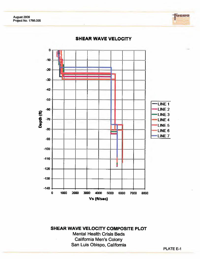


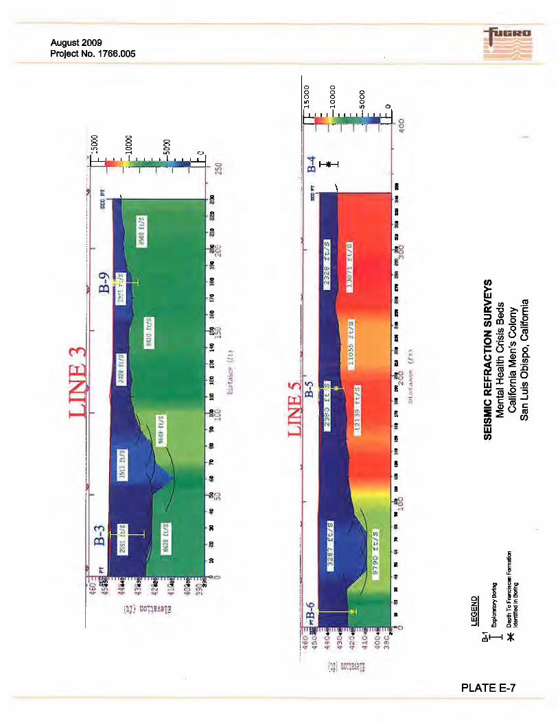

APPENDIX F
SOIL SHRINKAGE POTENTIAL

Draft Geotechnical Investigation Report for California Men’s Colony, MHCB Project
San Luis Obispo, California / August, 2009 (Project No. 1766.005)
- F1 -
ESTIMATED SOIL SHRINKAGE POTENTIAL
Boring No. Test
Depth (ft)
In-Place Dry
Density (pcf)
Maximum
Dry
Density*
(pcf)
Percentage
Shrinkage
at 92%
Comp.
In-Place
Moisture (%)
Optimum
Moisture*
(%)
B-2 4 128.4 130 -7 9.7 9.5
B-6 2.5 113.9 130 5 13.8 9.5
B-7 4 139.0 122.5 -19* 7.6 13.5
B-10 2.5 119.8 124.5 -4 13.6 12
B-10 7 123.9 122.5 -9 9.1 13.5
B-13 4 133.0 124.5 -14* 3.6 12
B-14 2.5 114.6 124.5 0 15.5 12
B-16 4 95.7 127 22* 15.4 11
B-19 2.5 121.0 127 -3 12.1 11
Note: * Values assumed anomalous