Draft ETSI EN 300 113-1 V1.6 - ETSI - Welcome to the … 3 Draft ETSI EN 300 113-1 V1.6.1 (2006-08)...
87
Draft ETSI EN 300 113-1 V1.6.1 (2006-08) European Standard (Telecommunications series) Electromagnetic compatibility and Radio spectrum Matters (ERM); Land mobile service; Radio equipment intended for the transmission of data (and/or speech) using constant or non-constant envelope modulation and having an antenna connector; Part 1: Technical characteristics and methods of measurement
Transcript of Draft ETSI EN 300 113-1 V1.6 - ETSI - Welcome to the … 3 Draft ETSI EN 300 113-1 V1.6.1 (2006-08)...

Draft ETSI EN 300 113-1 V1.6.1 (2006-08)
European Standard (Telecommunications series)
Electromagnetic compatibilityand Radio spectrum Matters (ERM);
Land mobile service;Radio equipment intended for the transmission
of data (and/or speech) using constant or non-constant envelopemodulation and having an antenna connector;
Part 1: Technical characteristics andmethods of measurement

ETSI
Draft ETSI EN 300 113-1 V1.6.1 (2006-08) 2
Reference REN/ERM-TGDMR-062-1
Keywords antenna, data, mobile, radio, speech, PMR
ETSI
650 Route des Lucioles F-06921 Sophia Antipolis Cedex - FRANCE
Tel.: +33 4 92 94 42 00 Fax: +33 4 93 65 47 16
Siret N° 348 623 562 00017 - NAF 742 C
Association à but non lucratif enregistrée à la Sous-Préfecture de Grasse (06) N° 7803/88
Important notice
Individual copies of the present document can be downloaded from: http://www.etsi.org
The present document may be made available in more than one electronic version or in print. In any case of existing or perceived difference in contents between such versions, the reference version is the Portable Document Format (PDF).
In case of dispute, the reference shall be the printing on ETSI printers of the PDF version kept on a specific network drive within ETSI Secretariat.
Users of the present document should be aware that the document may be subject to revision or change of status. Information on the current status of this and other ETSI documents is available at
http://portal.etsi.org/tb/status/status.asp
If you find errors in the present document, please send your comment to one of the following services: http://portal.etsi.org/chaircor/ETSI_support.asp
Copyright Notification
No part may be reproduced except as authorized by written permission. The copyright and the foregoing restriction extend to reproduction in all media.
© European Telecommunications Standards Institute 2006.
All rights reserved.
DECTTM, PLUGTESTSTM and UMTSTM are Trade Marks of ETSI registered for the benefit of its Members. TIPHONTM and the TIPHON logo are Trade Marks currently being registered by ETSI for the benefit of its Members. 3GPPTM is a Trade Mark of ETSI registered for the benefit of its Members and of the 3GPP Organizational Partners.
ETSI
Draft ETSI EN 300 113-1 V1.6.1 (2006-08) 3
Contents
Intellectual Property Rights ................................................................................................................................7
Foreword.............................................................................................................................................................7
1 Scope ........................................................................................................................................................8
2 References ................................................................................................................................................8
3 Definitions, symbols and abbreviations ...................................................................................................9 3.1 Definitions..........................................................................................................................................................9 3.2 Symbols............................................................................................................................................................10 3.3 Abbreviations ...................................................................................................................................................10
4 General ...................................................................................................................................................11 4.1 Presentation of equipment for testing purposes................................................................................................11 4.1.1 Choice of model for testing ........................................................................................................................11 4.1.1.1 Auxiliary test equipment .......................................................................................................................11 4.1.1.2 Declarations by the provider .................................................................................................................11 4.2 Mechanical and electrical design......................................................................................................................11 4.2.1 General........................................................................................................................................................11 4.2.2 Controls ......................................................................................................................................................11 4.2.3 Transmitter shut-off facility........................................................................................................................12 4.3 Marking ............................................................................................................................................................12 4.4 Testing using bit streams or messages..............................................................................................................12 4.5 Measuring continuous mode equipment...........................................................................................................12 4.6 Measuring discontinuous mode equipment ......................................................................................................12 4.7 Combined full bandwidth analogue speech/full bandwidth digital equipment.................................................12 4.8 Constant and non-constant envelope modulation .............................................................................................13
5 Test conditions, power sources and ambient temperatures ....................................................................13 5.1 Normal and extreme test conditions .................................................................................................................13 5.2 Test power source.............................................................................................................................................14 5.3 Normal test conditions......................................................................................................................................14 5.3.1 Normal temperature and humidity ..............................................................................................................14 5.3.2 Normal test power source ...........................................................................................................................14 5.3.2.1 Mains voltage ........................................................................................................................................14 5.3.2.2 Regulated lead-acid battery power sources used on vehicles................................................................14 5.3.2.3 Other power sources..............................................................................................................................14 5.4 Extreme test conditions ....................................................................................................................................15 5.4.1 Extreme temperatures .................................................................................................................................15 5.4.2 Extreme test source voltages.......................................................................................................................15 5.4.2.1 Mains voltage ........................................................................................................................................15 5.4.2.2 Regulated lead-acid battery power sources used on vehicles................................................................15 5.4.2.3 Power sources using other types of batteries.........................................................................................15 5.4.2.4 Other power sources..............................................................................................................................15 5.5 Procedure for tests at extreme temperatures.....................................................................................................16 5.5.1 Procedure for equipment designed for continuous transmission.................................................................16 5.5.2 Procedure for equipment designed for intermittent transmission ...............................................................16 5.5.3 Testing of equipment that does not have an external 50 Ω RF connector (integral antenna
equipment) ..................................................................................................................................................16
6 General conditions..................................................................................................................................17 6.1 Arrangements for test signals applied to the receiver input..............................................................................17 6.2 Receiver mute or squelch facility .....................................................................................................................17 6.3 Normal test signals (wanted and unwanted signals).........................................................................................17 6.3.1 Equipment measured as constant envelope angle modulation equipment ..................................................17 6.3.2 Equipment measured as non-constant envelope modulation equipment.....................................................18 6.4 Encoder for receiver measurements .................................................................................................................18 6.5 Transceiver data interface.................................................................................................................................19 6.6 Impedance ........................................................................................................................................................19

ETSI
Draft ETSI EN 300 113-1 V1.6.1 (2006-08) 4
6.7 Artificial antenna..............................................................................................................................................19 6.8 Tests of equipment with a duplex filter ............................................................................................................19 6.9 Facilities for access ..........................................................................................................................................19 6.9.1 Analogue access..........................................................................................................................................19 6.9.2 Test points for bit stream measurements.....................................................................................................20 6.9.3 Coupling arrangements ...............................................................................................................................20 6.9.3.1 Arrangements for measurements with continuous bit streams..............................................................20 6.9.3.2 Arrangements for measurements with messages...................................................................................20 6.10 Test site and general arrangements for measurements involving the use of radiated fields .............................20 6.11 Modes of operation of the transmitter ..............................................................................................................21
7 Technical characteristics of the transmitter............................................................................................21 7.1 Frequency error ................................................................................................................................................21 7.1.1 Definition....................................................................................................................................................21 7.1.2 Method of measurement .............................................................................................................................21 7.1.3 Limits..........................................................................................................................................................22 7.2 Carrier power (conducted)................................................................................................................................22 7.2.1 Definitions ..................................................................................................................................................22 7.2.1.1 Equipment measured as constant envelope angle modulation equipment.............................................22 7.2.1.2 Equipment measured as non-constant envelope modulation equipment ...............................................22 7.2.2 Method of measurement .............................................................................................................................23 7.2.2.1 Equipment measured as constant envelope angle modulation equipment.............................................23 7.2.2.2 Equipment measured as non-constant envelope modulation equipment ...............................................23 7.2.3 Limits..........................................................................................................................................................23 7.3 Maximum Effective radiated power (field strength) ........................................................................................23 7.3.1 Definition....................................................................................................................................................24 7.3.1.1 Equipment measured as constant envelope angle modulation equipment.............................................24 7.3.1.2 Equipment measured as non-constant envelope modulation equipment ...............................................24 7.3.2 Methods of measurement............................................................................................................................24 7.3.2.1 Equipment measured as constant envelope angle modulation equipment.............................................25 7.3.2.2 Equipment measured as non-constant envelope modulation equipment ...............................................26 7.3.3 Limits..........................................................................................................................................................27 7.4 Adjacent channel power ...................................................................................................................................28 7.4.1 Definition....................................................................................................................................................28 7.4.2 Method of measurement .............................................................................................................................28 7.4.3 Limits..........................................................................................................................................................29 7.5 Spurious emissions ...........................................................................................................................................29 7.5.1 Definition....................................................................................................................................................29 7.5.2 Method of measuring the power level ........................................................................................................30 7.5.2.1 Equipment measured as constant envelope angle modulation equipment.............................................30 7.5.2.2 Equipment measured as non-constant envelope modulation equipment ...............................................31 7.5.3 Method of measuring the effective radiated power.....................................................................................31 7.5.3.1 Equipment measured as constant envelope angle modulation equipment.............................................32 7.5.3.2 Equipment measured as non-constant envelope modulation equipment ...............................................32 7.5.4 Limits..........................................................................................................................................................34 7.6 Intermodulation attenuation..............................................................................................................................34 7.6.1 Definition....................................................................................................................................................34 7.6.2 Method of measurement .............................................................................................................................35 7.6.3 Limits..........................................................................................................................................................36 7.7 Transmitter attack time.....................................................................................................................................36 7.7.1 Definition....................................................................................................................................................36 7.7.2 Method of measurement .............................................................................................................................36 7.7.3 Limit ...........................................................................................................................................................37 7.8 Transmitter release time ...................................................................................................................................37 7.8.1 Definition....................................................................................................................................................37 7.8.2 Method of measurement .............................................................................................................................37 7.8.3 Limits..........................................................................................................................................................38 7.9 Transient behaviour of the transmitter..............................................................................................................38 7.9.1 Definitions ..................................................................................................................................................38 7.9.2 Timings, frequencies and powers ...............................................................................................................40 7.9.3 Methods of measurement............................................................................................................................43 7.9.3.1 Time domain measurements of power and frequency...........................................................................43

ETSI
Draft ETSI EN 300 113-1 V1.6.1 (2006-08) 5
7.9.3.2 Test arrangement and characteristics of the FM modulation meter ......................................................44 7.9.3.3 Adjacent channel transient power measurements..................................................................................44 7.9.3.3.1 Definition.........................................................................................................................................44 7.9.3.3.2 Measurement method for constant envelope angle modulation equipment.....................................44 7.9.3.3.3 Measurement method for non-constant envelope modulation equipment .......................................45 7.9.3.4 Characteristics of the adjacent channel transient power measuring device...........................................47 7.9.4 Limits..........................................................................................................................................................47 7.9.4.1 Time domain analysis of power and frequency.....................................................................................47 7.9.4.2 Adjacent channel transient power .........................................................................................................48 7.9.4.2.1 Equipment measured as constant envelope angle modulation equipment .......................................48 7.9.4.2.2 Equipment measured as non-constant envelope modulation equipment .........................................48
8 Methods of measurement for receiver parameters .................................................................................49 8.1 Maximum usable sensitivity (digital, conducted).............................................................................................49 8.1.1 Definition....................................................................................................................................................49 8.1.2 Method of measurement .............................................................................................................................49 8.1.2.1 Method of measurement with continuous bit streams ...........................................................................49 8.1.2.2 Method of measurement with messages................................................................................................50 8.1.3 Limits..........................................................................................................................................................50 8.2 Average usable sensitivity (digital, field strength) ...........................................................................................50 8.2.1 Definition....................................................................................................................................................50 8.2.2 Method of measurement .............................................................................................................................51 8.2.3 Limits..........................................................................................................................................................51 8.3 Level of the wanted signal for the degradation measurements (data or messages) ..........................................51 8.4 Error behaviour at high input levels .................................................................................................................51 8.4.1 Definition....................................................................................................................................................51 8.4.2 Method of measurement .............................................................................................................................51 8.4.2.1 Method of measurement with continuous bit streams ...........................................................................51 8.4.2.2 Method of measurement with messages................................................................................................52 8.4.3 Limits..........................................................................................................................................................52 8.5 Co-channel rejection.........................................................................................................................................52 8.5.1 Definition....................................................................................................................................................52 8.5.2 Method of measurement .............................................................................................................................53 8.5.2.1 Method of measurement with continuous bit streams ...........................................................................53 8.5.2.2 Method of measurement with messages................................................................................................54 8.5.3 Limits..........................................................................................................................................................55 8.6 Adjacent channel selectivity.............................................................................................................................55 8.6.1 Definition....................................................................................................................................................55 8.6.2 Method of measurement .............................................................................................................................55 8.6.2.1 Method of measurement with continuous bit streams ...........................................................................55 8.6.2.2 Method of measurement with messages................................................................................................56 8.6.3 Limits..........................................................................................................................................................57 8.7 Spurious response rejection..............................................................................................................................58 8.7.1 Definition....................................................................................................................................................58 8.7.2 Introduction to the method of measurement ...............................................................................................58 8.7.3 Method of search over the "limited frequency range" ................................................................................59 8.7.4 Method of measurement with continuous bit streams.................................................................................59 8.7.5 Method of measurement with messages .....................................................................................................60 8.7.6 Limits..........................................................................................................................................................61 8.8 Intermodulation response rejection ..................................................................................................................61 8.8.1 Definition....................................................................................................................................................61 8.8.2 Method of measurement .............................................................................................................................62 8.8.2.1 Method of measurement with continuous bit streams ...........................................................................62 8.8.2.2 Method of measurement with messages................................................................................................63 8.8.3 Limits..........................................................................................................................................................64 8.9 Blocking or desensitization ..............................................................................................................................64 8.9.1 Definition....................................................................................................................................................64 8.9.2 Method of measurement .............................................................................................................................64 8.9.2.1 Method of measurement with continuous bit streams ...........................................................................64 8.9.2.2 Method of measurement with messages................................................................................................65 8.9.3 Limits..........................................................................................................................................................67 8.10 Spurious radiations ...........................................................................................................................................67

ETSI
Draft ETSI EN 300 113-1 V1.6.1 (2006-08) 6
8.10.1 Definition....................................................................................................................................................67 8.10.2 Method of measuring the power level ........................................................................................................67 8.10.3 Method of measuring the effective radiated power.....................................................................................68 8.10.4 Limits..........................................................................................................................................................69
9 Duplex operation ....................................................................................................................................70 9.1 Receiver desensitization (with simultaneous transmission and reception).......................................................70 9.1.1 Definition....................................................................................................................................................70 9.1.2 Desensitization measured with continuous bit streams...............................................................................70 9.1.2.1 Method of measurement when the equipment has a duplex filter .........................................................70 9.1.2.2 Method of measurement when the equipment has to operate with two antennas..................................71 9.1.3 Desensitization measured with messages ...................................................................................................72 9.1.3.1 Method of measurement when the equipment has a duplex filter .........................................................72 9.1.3.2 Method of measurement when the equipment has to operate with two antennas..................................73 9.1.4 Limits..........................................................................................................................................................73 9.2 Receiver spurious response rejection (with simultaneous transmission and reception) ...................................74 9.2.1 Definition....................................................................................................................................................74 9.2.2 Method of measurement .............................................................................................................................74 9.2.3 Limits..........................................................................................................................................................74
10 Measurement uncertainty .......................................................................................................................75
Annex A (normative): Radiated measurement..................................................................................76
A.1 Test sites and general arrangements for measurements involving the use of radiated fields .................76 A.1.1 Anechoic chamber ............................................................................................................................................76 A.1.2 Anechoic chamber with a conductive ground plane.........................................................................................77 A.1.3 Open Area Test Site (OATS) ...........................................................................................................................78 A.1.4 Test antenna......................................................................................................................................................79 A.1.5 Substitution antenna .........................................................................................................................................80 A.1.6 Measuring antenna ...........................................................................................................................................80
A.2 Guidance on the use of radiation test sites .............................................................................................80 A.2.1 Verification of the test site ...............................................................................................................................80 A.2.2 Preparation of the EUT.....................................................................................................................................80 A.2.3 Power supplies to the EUT...............................................................................................................................80 A.2.4 Volume control setting for analogue speech tests ............................................................................................81 A.2.5 Range length.....................................................................................................................................................81 A.2.6 Site preparation ................................................................................................................................................82
A.3 Coupling of signals.................................................................................................................................82 A.3.1 General .............................................................................................................................................................82 A.3.2 Data Signals......................................................................................................................................................82 A.3.3 Speech and analogue signals ............................................................................................................................82 A.3.3.1 Acoustic coupler description.......................................................................................................................83 A.3.3.2 Calibration ..................................................................................................................................................83
Annex B (normative): Specification for some particular measurement arrangements.................84
B.1 Power measuring receiver specification.................................................................................................84 B.1.1 IF filter .............................................................................................................................................................84 B.1.2 Attenuation indicator ........................................................................................................................................85 B.1.3 RMS value indicator.........................................................................................................................................85 B.1.4 Oscillator and amplifier....................................................................................................................................85
B.2 Spectrum analyser specification.............................................................................................................86
B.3 Integrating and power summing device .................................................................................................86
History ..............................................................................................................................................................87
ETSI
Draft ETSI EN 300 113-1 V1.6.1 (2006-08) 7
Intellectual Property Rights IPRs essential or potentially essential to the present document may have been declared to ETSI. The information pertaining to these essential IPRs, if any, is publicly available for ETSI members and non-members, and can be found in ETSI SR 000 314: "Intellectual Property Rights (IPRs); Essential, or potentially Essential, IPRs notified to ETSI in respect of ETSI standards", which is available from the ETSI Secretariat. Latest updates are available on the ETSI Web server (http://webapp.etsi.org/IPR/home.asp).
Pursuant to the ETSI IPR Policy, no investigation, including IPR searches, has been carried out by ETSI. No guarantee can be given as to the existence of other IPRs not referenced in ETSI SR 000 314 (or the updates on the ETSI Web server) which are, or may be, or may become, essential to the present document.
Foreword This European Standard (Telecommunications series) has been produced by ETSI Technical Committee Electromagnetic compatibility and Radio spectrum Matters (ERM), and is now submitted for the Public Enquiry phase of the ETSI standards Two-step Approval Procedure.
The present document is part 1 of a multi-part deliverable covering the Electromagnetic compatibility and Radio spectrum Matters (ERM); Land mobile service; Radio equipment intended for the transmission of data (and/or speech) using constant or non-constant envelope modulation and having an antenna connector;
Part 1: "Technical characteristics and methods of measurement";
Part 2: "Harmonized EN covering essential requirements under article 3.2 of the R&TTE Directive".
Proposed national transposition dates
Date of latest announcement of this EN (doa): 3 months after ETSI publication
Date of latest publication of new National Standard or endorsement of this EN (dop/e):
6 months after doa
Date of withdrawal of any conflicting National Standard (dow): 6 months after doa

ETSI
Draft ETSI EN 300 113-1 V1.6.1 (2006-08) 8
1 Scope The present document covers the technical requirements for radio transmitters and receivers used in stations in the Private Mobile Radio (PMR) service.
It applies to use in the land mobile service, operating on radio frequencies between 30 MHz and 1 GHz, with channel separations of 12,5 kHz, 20 kHz and 25 kHz, intended for speech and/or data.
It applies to equipment for continuous and/or discontinuous transmission of data and/or digital speech.
The equipment comprises a transmitter and associated encoder and modulator and/or a receiver and associated demodulator and decoder. The types of equipment covered by the present document are as follows:
• base station (equipment fitted with an antenna socket, intended for use in a fixed location);
• mobile station (equipment fitted with an antenna socket, normally used in a vehicle or as a transportable);
• and those hand portable stations:
a) fitted with an antenna socket; or
b) without an external antenna socket (integral antenna equipment), but fitted with a permanent internal or a temporary internal 50 Ω Radio Frequency (RF) connector which allows access to the transmitter output and the receiver input.
Hand portable equipment without an external or internal RF connector and without the possibility of having a temporary internal 50 Ω RF connector is not covered by the present document.
2 References The following documents contain provisions which, through reference in this text, constitute provisions of the present document.
• References are either specific (identified by date of publication and/or edition number or version number) or non-specific.
• For a specific reference, subsequent revisions do not apply.
• For a non-specific reference, the latest version applies.
Referenced documents which are not found to be publicly available in the expected location might be found at http://docbox.etsi.org/Reference.
[1] ETSI EN 300 086-1 (V1.2.1 - 2001-03): "Electromagnetic compatibility and Radio spectrum Matters (ERM); Land Mobile Service; Radio equipment with an internal or external RF connector intended primarily for analogue speech; Part 1: Technical characteristics and methods of measurement".
[2] ETSI EN 300 390-1 (V1.2.1 - 2000-09): "Electromagnetic compatibility and Radio spectrum Matters (ERM); Land Mobile Service; Radio equipment intended for the transmission of data (and speech) and using an integral antenna; Part 1: Technical characteristics and test conditions".
[3] ETSI TR 100 028 (V1.4.1 - 2001-12) (all parts): "Electromagnetic compatibility and Radio spectrum Matters (ERM); Uncertainties in the measurement of mobile radio equipment characteristics".
[4] ETSI TR 102 273 (V1.2.1 - 2001-12) (all parts): "Electromagnetic compatibility and Radio spectrum Matters (ERM); Improvement of radiated methods of measurement (using test sites) and evaluation of the corresponding measurement uncertainties".
ETSI
Draft ETSI EN 300 113-1 V1.6.1 (2006-08) 9
[5] ITU-T Recommendation O.153: "Basic parameters for the measurement of error performance at bit rates below the primary rate".
[6] ANSI C63.5 (2004): "American National Standard for Electromagnetic Compatibility-Radiated Emission Measurements in Electromagnetic Interference (EMI) Control-Calibration of Antennas (9 kHz to 40 GHz)".
[7] IEC 60489-3 (1988): "Methods of measurement for radio equipment used in the mobiles services. Part 3: Receivers for A3E or F3E emissions".
[8] CEPT/ERC/REC 74-01E: "Unwanted emissions in the spurious domain". (Siófok 1998, Nice 1999, Sesimbra 2002 Hradec Kralove 2005).
[9] Directive 1999/5/EC of the European Parliament and of the Council of 9 March 1999 on radio equipment and telecommunications terminal equipment and the mutual recognition of their conformity (R&TTE Directive).
[10] ETSI EN 300 793 (V1.1.1 - 1998-02): "Electromagnetic compatibility and Radio spectrum Matters (ERM); Land mobile service; Presentation of equipment for type testing".
3 Definitions, symbols and abbreviations
3.1 Definitions For the purposes of the present document, the following terms and definitions apply:
angle modulation: either phase modulation or frequency modulation
base station: equipment fitted with an antenna socket, for use with an external antenna, and intended for use in a fixed location
bit: binary digit
block: the smallest quantity of information that is sent over the radio channel
NOTE: A constant number of useful bits are always sent together with the corresponding redundancy bits.
burst or transmission (physical): one or several packets transmitted between power on and power off of a particular transmitter
conducted measurements: measurements which are made using direct 50 Ω connection to the equipment under test
hand portable station: equipment either fitted with an antenna socket or integral antenna, or both, normally used on a stand-alone basis, to be carried on a person or held in the hand
integral antenna: antenna designed as a fixed part of the equipment, without the use of an external connector and as such which can not be disconnected from the equipment by the user
NOTE: An integral antenna may be fitted internally or externally. In case the antenna is external, the use of a non-detachable cable or waveguide is allowed.
Listen Before Transmit mode (LBT): monitoring mode in which the RF channel is checked for activity before transmitting
NOTE: Examples for LBT are transceivers or systems implementing squelch, CTCSS (Continuous Tone Control Squelch System), RSSI (Receiver Signal Strength Indicator), algorithms evaluating the status of the channel.
message: user data to be transferred in one or more packets in a session
mobile station: mobile equipment fitted with an antenna socket, for use with an external antenna, normally used in a vehicle or as a transportable station

ETSI
Draft ETSI EN 300 113-1 V1.6.1 (2006-08) 10
packet: one block or a contiguous stream of blocks sent by one (logical) transmitter to one particular receiver or one particular group of receivers
Peak Envelope Power (PEP): mean power delivered to the artificial antenna during a radio frequency cycle at the highest crest of the modulation envelope
radiated measurements: measurements which involve the absolute measurement of a radiated field
session: set of inter-related exchange of packets occupying one or several windows or part thereof (if applicable)
NOTE: It corresponds to a complete interactive procedure for interchanging data between users, comprising initiation, data transmission and termination procedures. The session can be short (e.g. 2 packets), or long (e.g. one full page of text).
window: set of inter-related transmissions which may be limited in time by an appropriate access protocol and corresponding occupation rules
3.2 Symbols For the purposes of the present document, the following symbols apply:
D-M0, D-M1... names of signals defined in clause 6.3
The symbols used in the clauses relating to transients and timings can be found in clause 7.9.
3.3 Abbreviations For the purposes of the present document, the following abbreviations apply:
CSP Channel SeParation CBW Channel BandWidth CW Continuous Wave dBc deciBels relative to the carrier power emf electromotive force EUT Equipment Under Test FSK Frequency Shift Keying GMSK Gaussian Minimum Shift Keying IF Intermediate Frequency OATS Open Area Test Site PEP Peak Envelope Power PLL Phase Locked Loop PMR Private Mobile Radio RF Radio Frequency rms root mean square SINAD SIgnal , Noise And Distortion sr switching range Tx Transmitter VSWR Voltage Standing Wave Ratio

ETSI
Draft ETSI EN 300 113-1 V1.6.1 (2006-08) 11
4 General
4.1 Presentation of equipment for testing purposes Each equipment submitted for testing shall fulfil the requirements of the present document on all frequencies over which it is intended to operate.
The provider shall declare the frequency ranges, the range of operating conditions and power requirements as applicable, to establish the appropriate test conditions.
Additionally, technical documentation and operating manuals, sufficient to make the test, shall be supplied.
Guidance on the presentation of equipment is also given in EN 300 793 [10].
4.1.1 Choice of model for testing
The provider shall provide one or more samples of the equipment, as appropriate for testing.
Stand-alone equipment shall be offered by the provider complete with any ancillary equipment needed for testing.
If an equipment has several optional features, considered not to affect the RF parameters then the tests need only to be performed on the equipment configured with the combination of features considered to be the most complex, as proposed by the provider and agreed by the test laboratory.
Where practicable, equipment offered for testing shall provide a 50 Ω connector for conducted RF power level measurements.
In the case of integral antenna equipment, if the equipment does not have a internal permanent 50 Ω connector then it is permissible to supply a second sample of the equipment with a temporary antenna connector fitted to facilitate testing.
The performance of the equipment submitted for testing shall be representative of the performance of the corresponding production model.
4.1.1.1 Auxiliary test equipment
All necessary test signal sources, setting up instructions and other product information shall accompany the equipment when it is submitted for testing.
4.1.1.2 Declarations by the provider
The provider shall declare the necessary information of the equipment with respect to all technical requirements set by the present document.
4.2 Mechanical and electrical design
4.2.1 General
The equipment shall be designed, constructed and manufactured in accordance with good engineering practice, and with the aim of minimizing harmful interference to other equipment and services.
4.2.2 Controls
Those controls, which if maladjusted, might increase the interfering potentialities of the equipment shall not be accessible for adjustment by the user.

ETSI
Draft ETSI EN 300 113-1 V1.6.1 (2006-08) 12
4.2.3 Transmitter shut-off facility
When a timer for an automatic shut-off facility is operative, at the moment of the time-out the transmitter shall automatically be switched off (the re-activation of the transmitter shall reset the timer).
A shut-off facility shall be inoperative for the duration of the measurements unless it has to remain operative to protect the equipment. If the shut-off facility is left operative the status of the equipment shall be indicated.
4.3 Marking The equipment shall be marked in a visible place. This marking shall be legible, tamperproof and durable.
The marking shall be in accordance with EC Directives and/or CEPT decisions or recommendations as appropriate.
4.4 Testing using bit streams or messages The manufacturer may elect to have the equipment tested using bit streams or messages. It should be noted that the methods of measurement using messages are usually more time consuming.
4.5 Measuring continuous mode equipment In the case of measurements performed on equipment designed to operate only in continuous mode, requirements such as "equipment shall be set in continuous mode" shall be interpreted as "equipment shall be used in its normal transmission mode (in this case, the continuous mode)".
4.6 Measuring discontinuous mode equipment When it is specified that the transmission shall be continuous for the duration of the measurement(s), the transmitter under test shall be set to operate in continuous mode. If this is not possible, the measurements shall be carried out in a period shorter than the duration of the transmitted burst. It may be necessary to extend the duration of the burst.
When measurements are made in discontinuous mode, the reported values can be average values. This averaging shall be made using a set of measurements, each of these measurements being made during a burst or a part of it.
4.7 Combined full bandwidth analogue speech/full bandwidth digital equipment
Equipment may be designed to fulfil the requirements of one or more standards.
In the case of combined full bandwidth analogue speech/full bandwidth digital equipment, if the analogue part of the equipment has already been measured according to EN 300 086-1 [1], only some additional tests have to be performed.
• 7.4 Adjacent channel power.
• 7.5 Spurious emissions.
• 7.7 Transmitter attack time.
• 7.8 Transmitter release time.
• 7.9 Transient behaviour of the transmitter.
• 8.1 Maximum usable sensitivity (data or messages, conducted).
• 8.2 Average usable sensitivity (data or messages, field strength) in the case of equipment having an integral antenna.

ETSI
Draft ETSI EN 300 113-1 V1.6.1 (2006-08) 13
• 8.4 Error behaviour at high input levels.
• 8.5 Co-channel rejection.
• 8.6 Adjacent channel selectivity.
More precisely, the measurement of the spurious emissions should be performed when equipment, previously measured to EN 300 086-1 [1], is being measured to the present document with an add-on data unit. If the equipment has been originally combined for analogue and digital operation, the measurement of the spurious emissions need not to be performed again if the data port(s) (and the data circuits/modules) were active while making this measurement for the test to EN 300 086-1 [1].
In the case where equipment has already been measured according to the present document and is to be measured again with an add-on data unit using another type of modulation without affecting any other characteristic of the equipment, only some additional tests should be performed:
• 7.4 Adjacent channel power.
• 7.5 Spurious emissions.
• 8.1 Maximum usable sensitivity (data or messages, conducted).
• 8.2 Average usable sensitivity (data or messages, field strength) in the case of equipment having an integral antenna.
• 8.4 Error behaviour at high input levels.
• 8.5 Co-channel rejection.
• 8.6 Adjacent channel selectivity.
The above mentioned tests shall be performed on one piece of equipment tuned to a frequency in the centre of the band.
In the case where data is transmitted simultaneously together with analogue speech, the speech part of the equipment is tested according to EN 300 086-1 [1] and it shall also be checked that the data does not cause the adjacent channel power and spurious emissions to fall outside the appropriate limits.
4.8 Constant and non-constant envelope modulation Constant envelope angle modulation systems can be measured following the measurement procedure either for constant envelope angle modulation equipment or for non-constant envelope modulation equipment.
Non-constant envelope modulation systems shall always be measured following the measurement procedure for non-constant envelope modulation equipment.
In both cases, the type of measurement procedure used shall be reported in the test report.
5 Test conditions, power sources and ambient temperatures
5.1 Normal and extreme test conditions Testing shall be made under normal test conditions, and also, where stated, under extreme test conditions.
The test conditions and procedures shall be as specified in clauses 5.2 to 5.5.
ETSI
Draft ETSI EN 300 113-1 V1.6.1 (2006-08) 14
5.2 Test power source During testing the power source of the equipment shall be replaced by a test power source capable of producing normal and extreme test voltages as specified in clauses 5.3.2 and 5.4.2. The internal impedance of the test power source shall be low enough for its effect on the test results to be negligible. For the purpose of tests, the voltage of the power source shall be measured at the input terminals of the equipment.
For battery operated equipment the battery shall be removed and the test power source shall be applied as close to the battery terminals as practicable.
During tests of DC powered equipment the power source voltages shall be maintained within a tolerance of < ±1 % relative to the voltage at the beginning of each test. The value of this tolerance is critical for power measurements, using a smaller tolerance will provide better measurement uncertainty values.
5.3 Normal test conditions
5.3.1 Normal temperature and humidity
The normal temperature and humidity conditions for tests shall be any convenient combination of temperature and humidity within the following ranges:
temperature: +15°C to +35°C;
relative humidity: 20 % to 75 %.
When it is impracticable to carry out the tests under these conditions, a note to this effect, stating the ambient temperature and relative humidity during the tests, shall be added to the test report.
5.3.2 Normal test power source
5.3.2.1 Mains voltage
The normal test voltage for equipment to be connected to the mains shall be the nominal mains voltage. For the purpose of the present document, the nominal voltage shall be the declared voltage or any of the declared voltages for which the equipment was designed.
The frequency of the test power source corresponding to the ac mains shall be between 49 Hz and 51 Hz.
5.3.2.2 Regulated lead-acid battery power sources used on vehicles
When the radio equipment is intended for operation from the usual types of regulated lead-acid battery power source used on vehicles the normal test voltage shall be 1,1 times the nominal voltage of the battery (for nominal voltages of 6 V and 12 V, these are 6,6 V and 13,2 V respectively).
5.3.2.3 Other power sources
For operation from other power sources or types of battery (primary or secondary), the normal test voltage shall be that declared by the equipment manufacturer.
ETSI
Draft ETSI EN 300 113-1 V1.6.1 (2006-08) 15
5.4 Extreme test conditions
5.4.1 Extreme temperatures
For tests at extreme temperatures, measurements shall be made in accordance with the procedures specified in clause 5.5, at the upper and lower temperatures of one of the following two ranges:
• -20°C to +55°C; All mobile and handportable equipment. Base stations for outdoor/uncontrolled climate conditions.
• 0°C to +40°C; Base stations for indoor/controlled climate conditions.
In the case of base stations equipment, the manufacturer shall declare which conditions the equipment is intended to be installed in.
5.4.2 Extreme test source voltages
5.4.2.1 Mains voltage
The extreme test voltage for equipment to be connected to an ac mains source shall be the nominal mains voltage ± 10 %.
5.4.2.2 Regulated lead-acid battery power sources used on vehicles
When the equipment is intended for operation from the usual types of regulated lead-acid battery power sources used on vehicles the extreme test voltages shall be 1,3 and 0,9 times the nominal voltage of the battery (for a nominal voltage of 6 V, these are 7,8 V and 5,4 V respectively and for a nominal voltage of 12 V, these are 15,6 V and 10,8 V respectively).
5.4.2.3 Power sources using other types of batteries
The lower extreme test voltages for equipment with power sources using batteries shall be as follows:
- for the nickel metal-hydride, leclanché or lithium type: 0,85 times the nominal battery voltage;
- for the mercury or nickel-cadmium type: 0,9 times the nominal battery voltage.
No upper extreme test voltages apply.
In the case where no upper extreme test voltage the nominal voltage is applicable, the corresponding four extreme test conditions are:
• Vmin/Tmin, Vmin/Tmax;
• (Vmax - nominal)/Tmin, (Vmax = nominal)/Tmax.
5.4.2.4 Other power sources
For equipment using other power sources, or capable of being operated from a variety of power sources, the extreme test voltages shall be those declared by the equipment manufacturer.

ETSI
Draft ETSI EN 300 113-1 V1.6.1 (2006-08) 16
5.5 Procedure for tests at extreme temperatures Before measurements are made the equipment shall have reached thermal balance in the test chamber. The equipment shall be switched off during the temperature stabilizing period.
In the case of equipment containing temperature stabilization circuits designed to operate continuously, the temperature stabilization circuits may be switched on for 15 minutes after thermal balance has been obtained, and the equipment shall then meet the specified requirements. For such equipment the manufacturer shall provide for the power source circuit feeding the crystal oven to be independent of the power source for the rest of the equipment.
If the thermal balance is not checked by measurements, a temperature stabilizing period of at least one hour, or a longer period as may be decided by the testing laboratory, shall be allowed. The sequence of measurements shall be chosen, and the humidity content in the test chamber shall be controlled so that excessive condensation does not occur.
5.5.1 Procedure for equipment designed for continuous transmission
If the manufacturer states that the equipment is designed for continuous transmission, the test procedure shall be as follows.
Before tests at the upper extreme temperature, the equipment shall be placed in the test chamber, and left until thermal balance is attained. The equipment shall then be switched on in the transmit condition for a period of half an hour, after which the equipment shall meet the specified requirements.
Before tests at the lower extreme temperature, the equipment shall be left in the test chamber until thermal balance is attained, then switched to the standby or receive condition for a period of one minute, after which the equipment shall meet the specified requirements.
5.5.2 Procedure for equipment designed for intermittent transmission
If the manufacturer states that the equipment is designed for intermittent transmission, the test procedure shall be as follows.
Before tests at the upper extreme temperature, the equipment shall be placed in the test chamber, and left until thermal balance is attained. The equipment shall then be switched on for one minute in the transmit condition, followed by four minutes in the receive condition, after which the equipment shall meet the specified requirements.
For tests at the lower extreme temperature, the equipment shall be left in the test chamber until thermal balance is attained, then switched to the standby or receive condition for one minute, after which the equipment shall meet the specified requirements.
5.5.3 Testing of equipment that does not have an external 50 Ω RF connector (integral antenna equipment)
Where equipment has an internal 50 Ω connector it shall be permitted to perform the tests at this connector.
Equipment may also have a temporary internal 50 Ω connector installed for the purposes of testing.
No connection shall be made to any internal permanent or temporary antenna connector during the performance of radiated emissions measurements, unless such action forms an essential part of the normal intended operation of the equipment, as declared by the manufacturer.

ETSI
Draft ETSI EN 300 113-1 V1.6.1 (2006-08) 17
6 General conditions
6.1 Arrangements for test signals applied to the receiver input Sources of test signals for application to the receiver input shall be connected in such a way that the source impedance presented to the receiver input is 50 Ω (non-reactive, clause 6.6).
This requirement shall be met irrespective of whether one or more signals using a combining network are applied to the receiver simultaneously.
The levels of the test signals at the receiver input terminals (RF socket) shall be expressed in terms of emf.
The effects of any intermodulation products and noise produced in the test signal sources shall be negligible.
6.2 Receiver mute or squelch facility If the receiver is equipped with a mute or squelch circuit, this shall be made inoperative for the duration of the measurements.
6.3 Normal test signals (wanted and unwanted signals)
6.3.1 Equipment measured as constant envelope angle modulation equipment
When the equipment is designed to transmit continuous bit streams (e.g. data, facsimile, image transmission, digital speech), the normal test signal shall be as follows:
• signal D-M0, consisting of an infinite series of 0 bits;
• signal D-M1, consisting of an infinite series of 1 bits;
• signal D-M2, consisting of a pseudo-random bit sequence of at least 511 bits according to ITU-T Recommendation O.153 [5];
• signal D-M2', this is the same type as D-M2, but the pseudo-random bit sequence is independent of D-M2 (perhaps identical with D-M2 but started at another point of time);
• signal A-M3, consisting of an RF signal, modulated by an audio frequency signal of 400 Hz with a deviation of 12 % of the channel separation. This signal is used as an unwanted signal.
Applying an infinite series of 0 bits or 1 bits does not normally produce the typical bandwidth. Signal D-M2 is designed to produce a good approximation of the typical bandwidth.
If the transmission of a continuous bit stream is not possible, the normal test signal shall be trains of correctly coded bits or messages. This signal shall be, as appropriate, either selected by the manufacturer or agreed between the manufacturer and the testing laboratory, and shall produce the greatest radio frequency occupied bandwidth. Details of this test signal shall be included in test reports.
In this case, the encoder, which is associated with the transmitter, shall be capable of supplying the normal test signal. The resulting modulation is called the normal test modulation. If possible this should be continuous modulation for the duration of the measurements.
For measurements using the up-down method (see note 1) it shall be possible to trigger single test signals "D-M3" either manually or by an automatic testing system.
The test signal D-M4 consists of correctly coded signals, messages transmitted sequentially, one by one, without gaps between them. This transmission is necessary for measurements such as adjacent channel power and spurious emissions.

ETSI
Draft ETSI EN 300 113-1 V1.6.1 (2006-08) 18
The signal A-M3 is used as an unwanted signal for measurements such as co-channel rejection and adjacent channel selectivity.
Details of D-M3 and D-M4 shall be recorded in test reports.
NOTE 1: A method of measurement implementing the "up-down method" can be found in clause 8.1.3 (method of measurement of the maximum usable sensitivity using messages).
NOTE 2: Transmitters may have limitations concerning their maximum continuous transmit time and/or their transmission duty cycle. It is intended that such limitations be respected during testing.
6.3.2 Equipment measured as non-constant envelope modulation equipment
When the equipment is designed to transmit continuous bit streams (e.g. data, facsimile, image transmission, digital speech) the normal test signal shall be as follows:
• signal D-M5, consisting of a pseudo-random bit sequence of at least 511 bits according to ITU-T Recommendation O.153 [5];
• signal D-M5', this is the same type as D-M5, but the pseudo-random bit sequence is independent of D-M5 (perhaps identical with D-M5 but started at another point of time);
• signal C1 shall be any signal that provides a constant envelope of output power at the output of the transmitter. This may be a CW tone or a modulated signal with constant envelope (e.g. GMSK). The envelope shall be flat to ±1 dB.
If the transmission of a continuous bit stream is not possible, the normal test signal D-M7 shall be trains of correctly coded bits or messages. This signal shall be, as appropriate, either selected by the manufacturer or agreed between the manufacturer and the testing laboratory, and shall produce the greatest radio frequency occupied bandwidth. Details of this test signal shall be included in test reports.
In this case, the encoder, which is associated with the transmitter, shall be capable of supplying the normal test signal. The resulting modulation is called the normal test modulation. If possible this should be continuous modulation for the duration of the measurements.
The test signal D-M7 consists of correctly coded signals, messages transmitted sequentially, one by one, without gaps between them. This transmission is necessary for measurements such as adjacent channel power and spurious emissions.
For the purpose of testing the carrier power, test signals D-M5 and D-M7 should produce the largest value of output power (PEP) possible with digital modulation. If this is not the case then a test signal that does produce the largest possible value of output power (PEP) with digital modulation should be used.
The PEP is the average power supplied to the artificial antenna by a transmitter during one RF cycle at the highest crest of the modulation envelope. For practical purposes the methods of measurements in clauses 7.2.2.2 and 7.3.2.2 should be used.
Details of D-M5 and D-M7 shall be recorded in test reports.
6.4 Encoder for receiver measurements Whenever needed, and in order to facilitate measurements on the receiver, an encoder for the data system is expected to accompany the equipment to be measured, together with details of the normal modulation process. The encoder is used to modulate a signal generator for use as a test signal source.
In the case of equipment unable to operate with continuous bit streams, the encoder shall be capable of operation in a repetitive mode, with intervals between each message that are not less than the reset time of the receiver.
Complete details of all codes and code format(s) used shall be made available for the measurements.

ETSI
Draft ETSI EN 300 113-1 V1.6.1 (2006-08) 19
6.5 Transceiver data interface Equipment that does not integrate the keyboard and display used for normal operation shall provide a V.24/V.28 interface (preferably) or other suitable interfaces.
In the case where the equipment uses a proprietary interface, appropriate means and documentation allowing for the equipment to be tested are expected to be provided in View of the measurements.
Variation in the level of the input signals, within the specified limits for that interface, shall have no measurable influence on the characteristics of the signals on the radio path.
6.6 Impedance In the present document the term "50 Ω" is used for a 50 Ω non-reactive impedance.
6.7 Artificial antenna Tests shall be carried out using an artificial antenna which shall be a substantially non-reactive non-radiating load of 50 Ω connected to the antenna connector.
NOTE: Some of the methods of measurement described in the present document for the transmitters allow for two or more different test set ups in order to perform that measurement, all supposed to provide equivalent results. The corresponding figures illustrate, therefore, one particular test set up and are given as examples. In many of those figures, power attenuators (providing a substantially non-reactive non-radiating load of 50 Ω to the antenna connector) have been shown (and not "artificial antennas" as defined here above).
6.8 Tests of equipment with a duplex filter If the equipment is provided with a built-in duplex filter or with a separate associated filter, the requirements of the present document shall be met when the measurements are carried out using the antenna connector of the filter.
6.9 Facilities for access
6.9.1 Analogue access
In order to simplify the measurements, temporary access to a point where the amplitude of the analogue output of the RF part can be measured should be provided, e.g. Intermediate Frequency (IF) output or the demodulated subcarrier point may be provided for the equipment to be tested. This access can be used to determine or verify the frequency where a spurious response is expected.

ETSI
Draft ETSI EN 300 113-1 V1.6.1 (2006-08) 20
6.9.2 Test points for bit stream measurements
It is recognized that it is not always possible to measure the air interface bit stream. The manufacturer shall define the test points at which the equipment shall be tested in order to make the measurements on bit streams according to clauses 7, 8 and 9.
Figure 1 is presented as an example for clarification only.
Application Datacoding
Modulation Air interface
De-modulation
Application
3 2 1 3'2'1'
Datadecoding
Figure 1: Test points for bit stream measurements
It should be noted that the closer the test access point is located to the air interface (figure 1), the fewer is the number of variants that may have to be measured because the measurement is less application dependent.
The tests shall be performed by use of corresponding test points (1,1' or 2,2' or 3,3').
The test points used shall be recorded in test reports.
6.9.3 Coupling arrangements
If the equipment does not have an external antenna connector, arrangements shall be made by the manufacturer to couple the unit to be tested to the test equipment by a method which does not affect the radiated field (e.g. acoustic, ultrasonic or optic) and according to clauses 6.9.3.1 and 6.9.3.2.
These arrangements are required for testing integral antenna equipment in accordance with EN 300 390-1 [2].
6.9.3.1 Arrangements for measurements with continuous bit streams
For the measurements of the receiver on a test site, arrangements to couple the unit to be tested to the bit error ratio measuring device shall be available (see clause 6.9.2).
Furthermore, the provider may also provide another facility to give access to the analogue information (see clause 6.9.1).
6.9.3.2 Arrangements for measurements with messages
For the measurement of the receiver on a test site, arrangements to couple the unit to be tested to the error observation device (or to an operator) shall be available.
Furthermore, the manufacturer shall also provide another facility to give access to the analogue information (see clause 6.9.1).
6.10 Test site and general arrangements for measurements involving the use of radiated fields
For guidance see annex A: descriptions of the radiated measurement arrangements are included in this annex.

ETSI
Draft ETSI EN 300 113-1 V1.6.1 (2006-08) 21
6.11 Modes of operation of the transmitter For the purpose of the measurements according to the present document, there should preferably be a facility to operate the transmitter unmodulated.
The method of obtaining an unmodulated carrier or special types of modulation patterns may also, as appropriate, either be selected by the manufacturer or be agreed between the manufacturer and the test laboratory. It shall be described in test reports.
It may involve suitable temporary internal modifications of the equipment under test. For instance in the case of direct Frequency Shift Keying (FSK), a means to continuously transmit a sequence D-M0 containing only "zeros" and a sequence D-M1 containing only "ones" is desirable.
7 Technical characteristics of the transmitter When performing transmitter tests on equipment designed for intermittent operation, the specified maximum transmit time shall not be exceeded.
The characteristics (continuous or discontinuous transmission, burst duration) of the transmission modes used for each of the following measurements shall be stated in the test report.
7.1 Frequency error This measurement is made if the equipment is capable of producing an unmodulated carrier or a modulated carrier, provided that the presence of modulation allows sufficiently accurate measurement of the carrier frequency. Otherwise the adjacent channel power shall also be measured under extreme test conditions. The equipment shall operate in continuous transmission mode during the time necessary to perform the measurement of the frequency.
7.1.1 Definition
The frequency error of the transmitter is the difference between the measured carrier frequency in the absence of modulation (or with modulation, provided that the presence of modulation allows sufficiently accurate measurement of the carrier frequency,) and the nominal frequency of the transmitter.
7.1.2 Method of measurement
Transmitterundertest
Powerattenuator
Frequencymeter
Figure 2: Measurement arrangement
The equipment shall be connected to the artificial antenna (see clause 6.7).
The carrier frequency shall be measured in the absence of modulation. The measurement shall be made under normal test conditions (see clause 5.3) and extreme test conditions (see clauses 5.4.1 and 5.4.2). The transmitter shall be set in continuous transmission mode. If this is not possible, the measurement shall be carried out in a period shorter than the duration of the transmitted burst. It may be necessary to extend the duration of the burst.

ETSI
Draft ETSI EN 300 113-1 V1.6.1 (2006-08) 22
7.1.3 Limits
The frequency error shall not exceed the values given in table 1, under normal and extreme test conditions, or in any intermediate set of conditions. However, for practical reasons the measurement shall be performed only at nominal and extreme test conditions.
Table 1: Frequency error
Channel separation
(kHz)
Frequency error limit (kHz)
below 47 MHz 47 MHz to 137 MHz
above 137 MHz to 300 MHz
above 300 MHz to 500 MHz
above 500 MHz to 1 000 MHz
20 and 25 ±0,60 ±1,35 ±2,00 ±2,00 (see note 2) ±2,50 (see note 2) 12,5 ±0,60 ±1,00 ±1,00 (B)
±1,50 (M) ±1,00 (B) ±1,50 (M)
(see note 2)
No value specified
NOTE 1: For hand portable stations having integral power supplies, these limits only apply to the reduced extreme temperature range 0°C to +40°C.
NOTE 2: However for the full extreme temperature conditions (see clause 5.4.1), exceeding the reduced extreme temperature range above, the following frequency error limits apply:
±2,50 kHz between 300 MHz and 500 MHz; ±3,00 kHz between 500 MHz and 1 000 MHz. NOTE 3: (B) base station. NOTE 4: (M) mobile station.
7.2 Carrier power (conducted) If the equipment is designed to operate with different carrier powers, the rated power for each level, or range of levels, shall be declared by the manufacturer. The power adjustment control shall not be accessible to the user.
The requirements of the present document shall be met for all power levels at which the transmitter is intended to operate. For practical reasons, measurements shall be performed only at the lowest and highest power level at which the transmitter is intended to operate.
7.2.1 Definitions
7.2.1.1 Equipment measured as constant envelope angle modulation equipment
The transmitter carrier power (conducted) is the mean power delivered to the artificial antenna during a radio frequency cycle.
The rated output power is the carrier power (conducted) of the equipment declared by the manufacturer.
7.2.1.2 Equipment measured as non-constant envelope modulation equipment
The transmitter carrier power (conducted) is the Peak Envelope Power (PEP); the mean power delivered to the artificial antenna during a radio frequency cycle at the highest crest of the modulation envelope.
The rated output power is the carrier power (conducted) of the equipment declared by the manufacturer.

ETSI
Draft ETSI EN 300 113-1 V1.6.1 (2006-08) 23
7.2.2 Method of measurement
7.2.2.1 Equipment measured as constant envelope angle modulation equipment
Transmitterundertest
Powerattenuator
Powermeter
Figure 3: Measurement arrangement
The measurement shall be performed preferably in the absence of modulation.
When it is not possible to measure it in the absence of modulation, this fact shall be stated in test reports (see clause 6.11).
The transmitter shall be set in continuous transmission mode. If this is not possible, the measurements shall be carried out in a period shorter than the duration of the transmitted burst. It may be necessary to extend the duration of the burst.
The transmitter shall be connected to an artificial antenna (see clause 6.7) and the power delivered to this artificial antenna shall be measured.
The measurement shall be made under normal test conditions (see clause 5.3) and extreme test conditions (see clauses 5.4.1 and 5.4.2).
7.2.2.2 Equipment measured as non-constant envelope modulation equipment
The measurement shall be performed with test signals D-M5 or D-M7 as appropriate.
The transmitter shall be preferably set in continuous transmission mode. If this is not possible, the measurement can be performed in discontinuous mode.
The transmitter shall be connected to an artificial antenna (see clause 6.7) and the power delivered to this artificial antenna shall be measured. The measuring instrument shall have a measurement bandwidth not less than sixteen times the channel bandwidth.
The measurement shall be made under normal test conditions (see clause 5.3) and extreme test conditions (see clauses 5.4.1 and 5.4.2 applied simultaneously).
7.2.3 Limits
The carrier power (conducted) under the specified conditions of measurement (see clause 7.2.2) and at normal test conditions (see clause 5.3), shall be within ±1,5 dB of the rated carrier power (conducted).
The carrier power (conducted) under extreme test conditions shall be within +2,0 dB and -3,0 dB of the rated output power.
7.3 Maximum Effective radiated power (field strength) This measurement applies only to equipment without an external antenna connector.
If the equipment is designed to operate with different carrier powers, the rated power for each level, or range of levels, shall be declared by the manufacturer. The power adjustment control shall not be accessible to the user.
The requirements of the present document shall be met for all power levels at which the transmitter is intended to operate. For practical reasons measurements shall be performed only at the lowest and highest power level at which the transmitter is intended to operate.
The measurement shall be carried out under normal test conditions only.

ETSI
Draft ETSI EN 300 113-1 V1.6.1 (2006-08) 24
7.3.1 Definition
7.3.1.1 Equipment measured as constant envelope angle modulation equipment
The effective radiated power is the power radiated in the direction of the maximum field strength under specified conditions of measurements.
The rated effective radiated power is the effective radiated power of the equipment as declared by the manufacturer.
7.3.1.2 Equipment measured as non-constant envelope modulation equipment
The effective radiated power of the transmitter is the value of the output PEP for any condition of modulation radiated in the direction of the maximum field strength.
7.3.2 Methods of measurement
1
Test site
2
3
1) Transmitter under test 2) Test antenna 3) Spectrum analyser or selective Voltmeter (test receiver)
Figure 4: Measurement arrangement

ETSI
Draft ETSI EN 300 113-1 V1.6.1 (2006-08) 25
1 4
Test site
2 3
1) Signal generator 2) Substitution antenna 3) Test antenna 4) Spectrum analyser or selective Voltmeter (test receiver)
Figure 5: Measurement arrangement
7.3.2.1 Equipment measured as constant envelope angle modulation equipment
The measurement shall be performed preferably in the absence of modulation.
When it is not possible to measure it in the absence of modulation this fact shall be stated in test reports (see clause 6.11).
The transmitter shall be set in continuous transmission mode. If this is not possible, each individual measurement of the mean power on the spectrum analyser or selective Voltmeter shall be carried out in a period shorter than the duration of the transmitted burst. It may be necessary to extend the duration of the burst.
The measurement procedure shall be as follows:
a) A test site, selected from annex A, which fulfils the requirements of the specified frequency range of this measurement shall be used. The test antenna shall be orientated initially for vertical polarization unless otherwise stated.
b) The transmitter under test shall be placed at the specified height on a non-conducting support in the position closest to normal use as declared by the manufacturer. This position shall be recorded in test reports.
c) The spectrum analyser or selective Voltmeter shall be tuned to the transmitter carrier frequency. The test antenna shall be raised or lowered through the specified height range until the maximum signal level is detected on the spectrum analyser or selective voltmeter.
d) The test antenna need not be raised or lowered if the measurement is carried out on a test site according to clause A.3 (i.e. an anechoic chamber).

ETSI
Draft ETSI EN 300 113-1 V1.6.1 (2006-08) 26
e) The transmitter shall be rotated through 360° about a vertical axis until a higher maximum signal is received.
f) The test antenna shall be raised or lowered again through the specified height range until a maximum is obtained. This level shall be recorded. (This maximum may be a lower value than the value obtainable at heights outside the specified limits).
g) The test antenna need not be raised or lowered if the measurement is carried out on a test site according to clause A.3 (i.e. an anechoic chamber).
h) Using the measurement arrangement of figure 5, the substitution antenna (see clauses A.1.3 to A.1.5) shall replace the transmitter antenna in the same position and in vertical polarization. The frequency of the signal generator shall be adjusted to the transmitter carrier frequency. The test antenna shall be raised or lowered as necessary to ensure that the maximum signal is still received.
i) The test antenna need not be raised or lowered if the measurement is carried out on a test site according to clause A.3 (i.e. an anechoic chamber).
j) The input signal to the substitution antenna shall be adjusted in level until an equal or a known related level to that detected from the transmitter is obtained in the test receiver. The maximum carrier radiated power is equal to the power supplied by the signal generator, increased by the known relationship if necessary and after corrections due to the gain of the substitution antenna and the cable loss between the signal generator and the substitution antenna.
k) Steps b) to e) above shall be repeated with the test antenna and the substitution antenna orientated in horizontal polarization.
The measure of the effective radiated power is the larger of the two power levels recorded at the input to the substitution antenna, corrected for the gain of the antenna if necessary.
7.3.2.2 Equipment measured as non-constant envelope modulation equipment
The transmitter shall be set in continuous transmission mode. If this is not possible, each individual measurement of the PEP and of the mean power shall be carried out in a period shorter than the duration of the transmitted burst. It may be necessary to extend the duration of the burst.
Evaluation of CW-to-PEP correction factor for signal C1: The transmitter permanent internal or a temporary internal 50 Ω RF connector shall be connected to a 50 Ω power attenuator. The transmitter shall be switched on with test signal C1 (see clause 7.9.2) applied and the PEP delivered shall be measured. The measuring instrument shall have a measurement bandwidth not less that sixteen times the CBW. The mean power delivered shall also be measured. The difference between the PEP and the mean power shall be less than 1 dB.
Modulation test signal D-M5 or D-M7 as appropriate shall then be applied at the transmitter. The PEP delivered to its artificial antenna shall be measured.
The difference (in dB) between the PEP measured for D-M5 or D-M7 modulation and the mean power measured for C1 modulation shall be recorded. This value is the CW-to-PEP correction factor for signal C1.
The measurement procedure shall be as follows:
a) A test site, selected from annex A, which fulfils the requirements of the specified frequency range of this measurement shall be used. The test antenna shall be orientated initially for Vertical polarization unless otherwise stated.
b) The transmitter under test shall be placed at the specified height on a non-conducting support in the position closest to normal use as declared by the manufacturer. This position shall be recorded in test reports.
c) The transmitter shall be switched on with test signal C1 applied and the spectrum analyser or selective voltmeter shall be tuned to the transmitter carrier frequency. The test antenna shall be raised or lowered through the specified height range until the maximum signal level is detected on the spectrum analyser or selective voltmeter.
d) The test antenna need not be raised or lowered if the measurement is carried out on a test site according to clause A.3 (i.e. an anechoic chamber).
e) The transmitter shall be rotated through 360° about a vertical axis until a higher maximum signal is received.

ETSI
Draft ETSI EN 300 113-1 V1.6.1 (2006-08) 27
f) The test antenna shall be raised or lowered again through the specified height range until a maximum is obtained. This level shall be recorded. (This maximum may be a lower value than the value obtainable at heights outside the specified limits).
g) The test antenna need not be raised or lowered if the measurement is carried out on a test site according to clause A.3 (i.e. an anechoic chamber).
h) Using the measurement arrangement of figure 5, the substitution antenna (see clauses A.1.3 to A.1.5) shall replace the transmitter antenna in the same position and in vertical polarization. The frequency of the signal generator shall be adjusted to the transmitter carrier frequency. The test antenna shall be raised or lowered as necessary to ensure that the maximum signal is still received.
i) The test antenna need not be raised or lowered if the measurement is carried out on a test site according to clause A.3 (i.e. an anechoic chamber).
j) The input signal to the substitution antenna shall be adjusted in level until an equal or a known related level to that detected from the transmitter is obtained in the test receiver. The maximum carrier radiated power is equal to the power supplied by the signal generator, corrected by the CW-to-PEP correction factor for signal C1, increased by the known relationship if necessary and after corrections due to the gain of the substitution antenna and the cable loss between the signal generator and the substitution antenna.
k) Steps b) to e) above shall be repeated with the test antenna and the substitution antenna orientated in horizontal polarization.
The measure of the effective radiated power is the larger of the two power levels recorded at the input to the substitution antenna, corrected for the gain of the antenna if necessary.
7.3.3 Limits
The effective radiated power under normal test conditions shall be within df from the rated effective radiated power.
The allowance for the characteristics of the equipment (±1,5 dB) shall be combined with the actual measurement uncertainty in order to provide df, as follows:
df2 = dm
2 + de2
where:
• dm is the actual measurement uncertainty;
• de is the allowance for the equipment (1,5 dB);
• df is the final difference.
All values shall be expressed in linear terms.
In all cases the actual measurement uncertainty shall comply with clause 10.
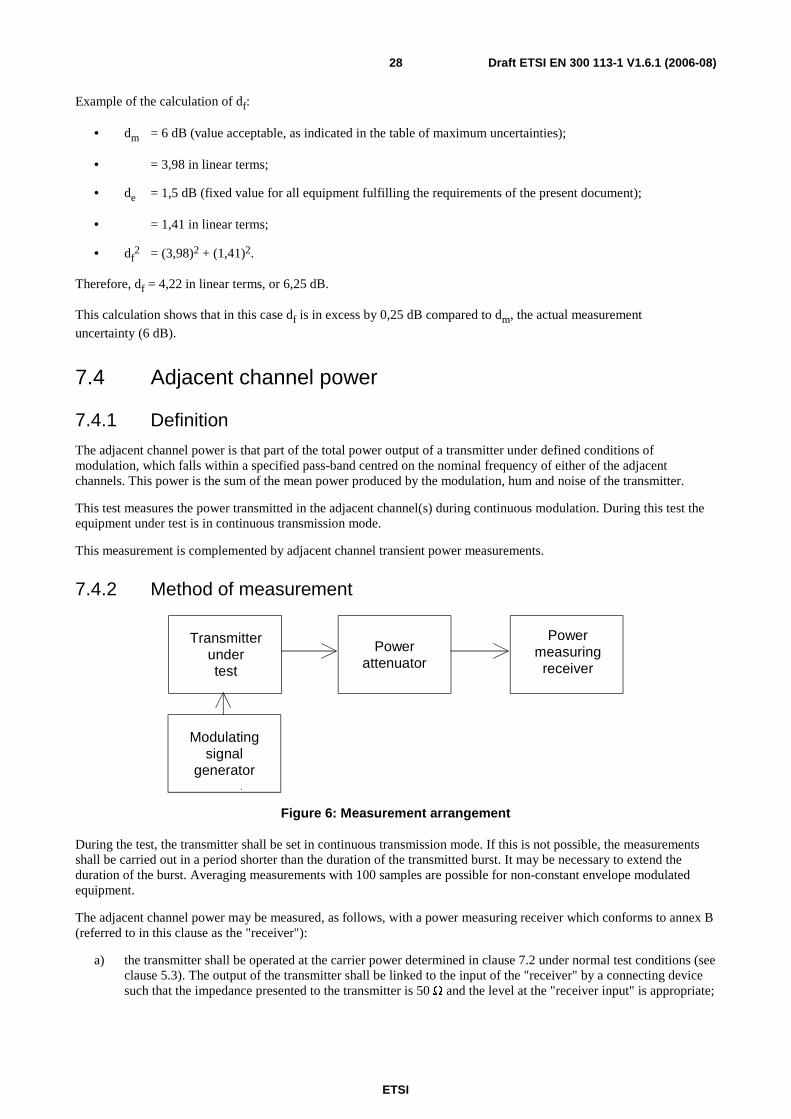
ETSI
Draft ETSI EN 300 113-1 V1.6.1 (2006-08) 28
Example of the calculation of df:
• dm = 6 dB (value acceptable, as indicated in the table of maximum uncertainties);
• = 3,98 in linear terms;
• de = 1,5 dB (fixed value for all equipment fulfilling the requirements of the present document);
• = 1,41 in linear terms;
• df2 = (3,98)2 + (1,41)2.
Therefore, df = 4,22 in linear terms, or 6,25 dB.
This calculation shows that in this case df is in excess by 0,25 dB compared to dm, the actual measurement
uncertainty (6 dB).
7.4 Adjacent channel power
7.4.1 Definition
The adjacent channel power is that part of the total power output of a transmitter under defined conditions of modulation, which falls within a specified pass-band centred on the nominal frequency of either of the adjacent channels. This power is the sum of the mean power produced by the modulation, hum and noise of the transmitter.
This test measures the power transmitted in the adjacent channel(s) during continuous modulation. During this test the equipment under test is in continuous transmission mode.
This measurement is complemented by adjacent channel transient power measurements.
7.4.2 Method of measurement
Transmitterundertest
Modulatingsignal
generator
Powerattenuator
Powermeasuring
receiver
Figure 6: Measurement arrangement
During the test, the transmitter shall be set in continuous transmission mode. If this is not possible, the measurements shall be carried out in a period shorter than the duration of the transmitted burst. It may be necessary to extend the duration of the burst. Averaging measurements with 100 samples are possible for non-constant envelope modulated equipment.
The adjacent channel power may be measured, as follows, with a power measuring receiver which conforms to annex B (referred to in this clause as the "receiver"):
a) the transmitter shall be operated at the carrier power determined in clause 7.2 under normal test conditions (see clause 5.3). The output of the transmitter shall be linked to the input of the "receiver" by a connecting device such that the impedance presented to the transmitter is 50 Ω and the level at the "receiver input" is appropriate;

ETSI
Draft ETSI EN 300 113-1 V1.6.1 (2006-08) 29
b) with the transmitter unmodulated, the tuning of the "receiver" shall be adjusted so that a maximum response is obtained. This is the 0 dB response point. The "receiver" attenuator setting and the reading of the meter shall be recorded. If an unmodulated carrier cannot be obtained, then the measurement shall be made with the transmitter modulated with the normal test signal D-M2, D-M4, D-M5 or D-M7 as appropriate, according to clause 6.3, in which case this fact shall be recorded in test reports;
c) the frequency of the "receiver" shall be adjusted above the carrier so that the "receiver" -6 dB response nearest to the transmitter carrier frequency is located at a displacement from the nominal carrier frequency as given in table 2;
Table 2: Frequency displacement
Channel separation (kHz) Specified necessary bandwidth (kHz)
Displacement from the -6 dB point (kHz)
12,5 8,5 8,25 20 14 13 25 16 17
d) the transmitter shall be modulated by a normal test signal D-M2 or D-M4 as appropriate, according to clause 6.3;
e) the "receiver" variable attenuator shall be adjusted to obtain the same meter reading as in step b), or a known relation to it;
f) the ratio of the adjacent channel power to the carrier power is the difference between the attenuator settings in steps b) and e), corrected for any differences in the reading of the meter.
For each adjacent channel, the adjacent channel power shall be recorded.
• the measurement shall be repeated with the frequency of the "receiver" adjusted below the carrier so that the "receiver" -6 dB response nearest to the transmitter carrier frequency is located at a displacement from the nominal carrier frequency as given in table 2;
• the adjacent channel power of the equipment under test shall be expressed as the higher of the two values recorded in step f) for the upper and lower channels nearest to the channel considered;
• when it is not possible to perform the measurement of frequency error in the absence of modulation (see clause 7.1), this measurement shall be repeated under extreme test conditions (see clauses 5.4.1 and 5.4.2 applied simultaneously).
7.4.3 Limits
For channel separations of 20 kHz and 25 kHz, the adjacent channel power shall not exceed a value of 70,0 dB below the carrier power (conducted) of the transmitter without any need to be below 0,2 µW (-37 dBm).
For a channel separation of 12,5 kHz, the adjacent channel power shall not exceed a value of 60,0 dB below the transmitter carrier power (conducted) without the need to be below 0,2 µW (-37 dBm).
7.5 Spurious emissions
7.5.1 Definition
Spurious emissions are emissions at frequencies other than those of the carrier and sidebands associated with normal modulation.
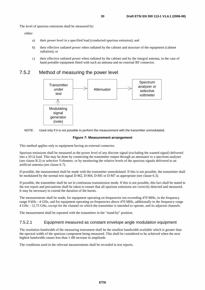
ETSI
Draft ETSI EN 300 113-1 V1.6.1 (2006-08) 30
The level of spurious emissions shall be measured by:
either:
a) their power level in a specified load (conducted spurious emission); and
b) their effective radiated power when radiated by the cabinet and structure of the equipment (cabinet radiation); or
c) their effective radiated power when radiated by the cabinet and by the integral antenna, in the case of hand portable equipment fitted with such an antenna and no external RF connector.
7.5.2 Method of measuring the power level
Transmitterundertest
Modulatingsignal
generator(note)
Attenuator
Spectrumanalyzer orselectivevoltmeter
NOTE: Used only if it is not possible to perform the measurement with the transmitter unmodulated.
Figure 7: Measurement arrangement
This method applies only to equipment having an external connector.
Spurious emissions shall be measured as the power level of any discrete signal (excluding the wanted signal) delivered into a 50 Ω load. This may be done by connecting the transmitter output through an attenuator to a spectrum analyser (see clause B.2) or selective Voltmeter, or by monitoring the relative levels of the spurious signals delivered to an artificial antenna (see clause 6.7).
If possible, the measurement shall be made with the transmitter unmodulated. If this is not possible, the transmitter shall be modulated by the normal test signal D-M2, D-M4, D-M5 or D-M7 as appropriate (see clause 6.3).
If possible, the transmitter shall be set in continuous transmission mode. If this is not possible, this fact shall be stated in the test report and precautions shall be taken to ensure that all spurious emissions are correctly detected and measured. It may be necessary to extend the duration of the bursts.
The measurements shall be made, for equipment operating on frequencies not exceeding 470 MHz, in the frequency range 9 kHz - 4 GHz, and for equipment operating on frequencies above 470 MHz, additionally in the frequency range 4 GHz - 12,75 GHz, except for the channel on which the transmitter is intended to operate, and its adjacent channels.
The measurement shall be repeated with the transmitter in the "stand-by" position.
7.5.2.1 Equipment measured as constant envelope angle modulation equipment
The resolution bandwidth of the measuring instrument shall be the smallest bandwidth available which is greater than the spectral width of the spurious component being measured. This shall be considered to be achieved when the next highest bandwidth causes less than 1 dB increase in amplitude.
The conditions used in the relevant measurements shall be recorded in test reports.
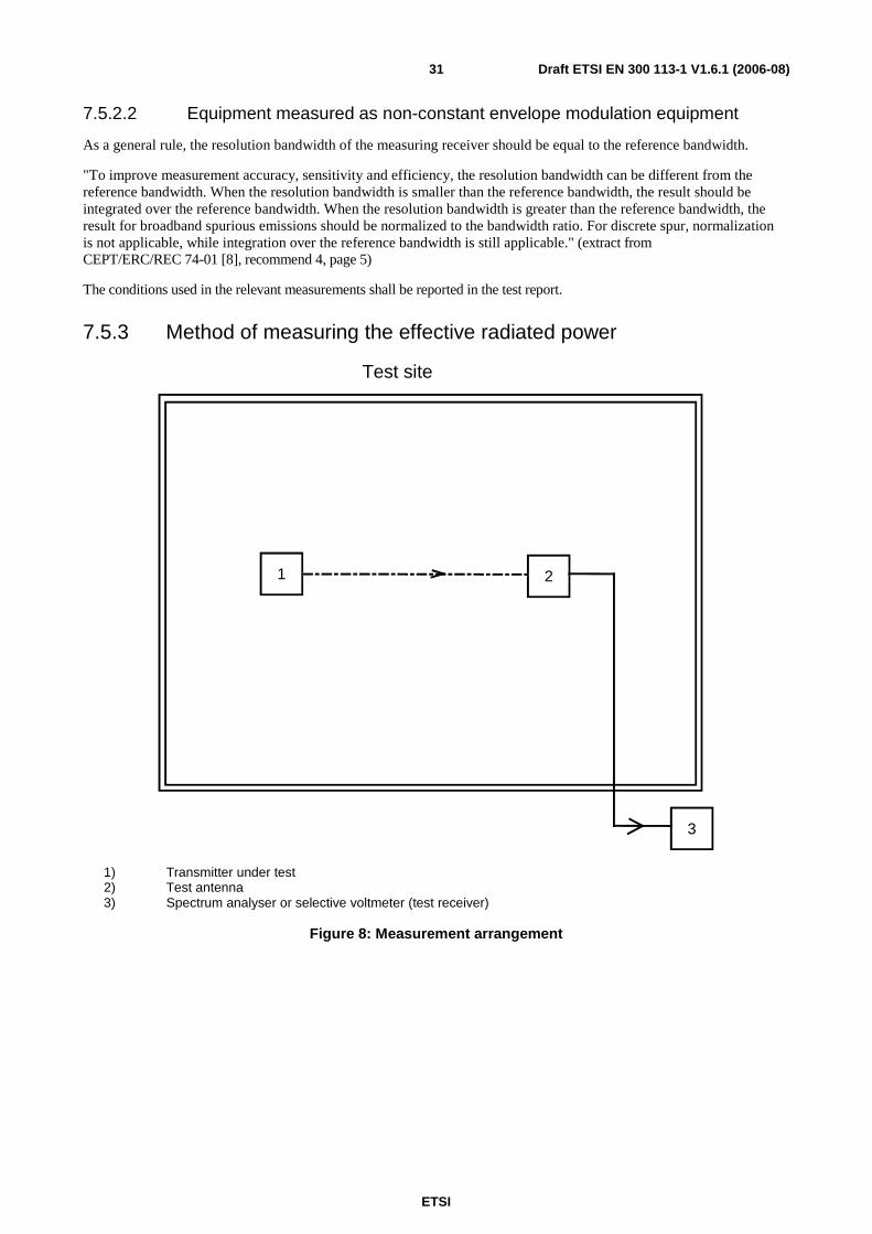
ETSI
Draft ETSI EN 300 113-1 V1.6.1 (2006-08) 31
7.5.2.2 Equipment measured as non-constant envelope modulation equipment
As a general rule, the resolution bandwidth of the measuring receiver should be equal to the reference bandwidth.
"To improve measurement accuracy, sensitivity and efficiency, the resolution bandwidth can be different from the reference bandwidth. When the resolution bandwidth is smaller than the reference bandwidth, the result should be integrated over the reference bandwidth. When the resolution bandwidth is greater than the reference bandwidth, the result for broadband spurious emissions should be normalized to the bandwidth ratio. For discrete spur, normalization is not applicable, while integration over the reference bandwidth is still applicable." (extract from CEPT/ERC/REC 74-01 [8], recommend 4, page 5)
The conditions used in the relevant measurements shall be reported in the test report.
7.5.3 Method of measuring the effective radiated power
1
Test site
2
3
1) Transmitter under test 2) Test antenna 3) Spectrum analyser or selective voltmeter (test receiver)
Figure 8: Measurement arrangement

ETSI
Draft ETSI EN 300 113-1 V1.6.1 (2006-08) 32
7.5.3.1 Equipment measured as constant envelope angle modulation equipment
The measurement procedure shall be as follows:
• On a test site, fulfilling the requirements of annex A, the sample shall be placed at the specified height on the support.
• The transmitter shall be operated at the carrier power as specified under clause 7.2, delivered to:
- an artificial antenna (see clause 6.7) for equipment having an external antenna connector; or
- to the integral antenna.
If possible, the measurement shall be made with the transmitter unmodulated. If this is not possible, the transmitter shall be modulated by the normal test signal D-M2, D-M4, D-M5 or D-M7 as appropriate (see clause 6.3).
If possible, the transmitter shall be set in continuous transmission mode. If this is not possible, this fact shall be stated in the test report and precautions shall be taken to ensure that all spurious emissions are correctly detected and measured. It may be necessary to extend the duration of the bursts.
The resolution bandwidth of the measuring instrument shall be the smallest bandwidth available which is greater than the spectral width of the spurious component being measured. This shall be considered to be achieved when the next highest bandwidth causes less than 1 dB increase in amplitude.
The conditions used in the relevant measurements shall be recorded in test reports.
• the radiation of any spurious components shall be detected by the test antenna and receiver, over the frequency range 30 MHz - 4 GHz, except for the channel on which the transmitter is intended to operate and its adjacent channels;
• at each frequency at which a component is detected, the sample shall be rotated to obtain maximum response and the effective radiated power of that component determined by a substitution measurement, using the measurement arrangement of figure 9;
• The value of the effective radiated power of that component shall be recorded;
• the measurements shall be repeated with the test antenna in the orthogonal polarization plane;
• the measurements shall be repeated with the transmitter in the "stand-by" position.
7.5.3.2 Equipment measured as non-constant envelope modulation equipment
The measurement procedure shall be as follows:
a) On a test site, fulfilling the requirements of annex A, the sample shall be placed at the specified height on the support.
b) The transmitter shall be operated at the carrier power as specified under clause 7.2, delivered to:
- an artificial antenna (see clause 6.7) for equipment having an external antenna connector; or
- to the integral antenna.
c) If possible, the measurement shall be made with the transmitter unmodulated. If this is not possible, the transmitter shall be modulated by the normal test signal, D-M5 or D-M7 as appropriate (see clause 6.3).
If possible, the transmitter shall be set in continuous transmission mode. If this is not possible, this fact shall be stated in the test report and precautions shall be taken to ensure that all spurious emissions are correctly detected and measured. It may be necessary to extend the duration of the bursts.

ETSI
Draft ETSI EN 300 113-1 V1.6.1 (2006-08) 33
As a general rule, the resolution bandwidth of the measuring receiver should be equal to the reference bandwidth.
"To improve measurement accuracy, sensitivity and efficiency, the resolution bandwidth can be different from the reference bandwidth. When the resolution bandwidth is smaller than the reference bandwidth, the result should be integrated over the reference bandwidth. When the resolution bandwidth is greater than the reference bandwidth, the result for broadband spurious emissions should be normalized to the bandwidth ratio. For discrete spur, normalization is not applicable, while integration over the reference bandwidth is still applicable." (extract from CEPT/ERC/REC 74-01, [8] recommend 4, page 5)
The conditions used in the relevant measurements shall be recorded in test reports.
c) the radiation of any spurious components shall be detected by the test antenna and receiver, over the frequency range 30 MHz - 4 GHz, except for the channel on which the transmitter is intended to operate and its adjacent channels;
d) at each frequency at which a component is detected, the sample shall be rotated to obtain maximum response and the effective radiated power of that component determined by a substitution measurement, using the measurement arrangement of figure 9.
The value of the effective radiated power of that component shall be recorded.
e) the measurements shall be repeated with the test antenna in the orthogonal polarization plane;
f) the measurements shall be repeated with the transmitter in the "stand-by" position.
1 4
Test site
2 3
1) Signal generator 2) Substitution antenna 3) Test antenna 4) Spectrum analyser or selective Voltmeter (test receiver)
Figure 9: Measurement arrangement
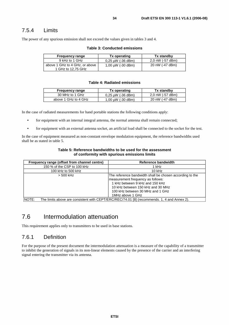
ETSI
Draft ETSI EN 300 113-1 V1.6.1 (2006-08) 34
7.5.4 Limits
The power of any spurious emission shall not exceed the values given in tables 3 and 4.
Table 3: Conducted emissions
Frequency range Tx operating Tx standby 9 kHz to 1 GHz 0,25 µW (-36 dBm) 2,0 nW (-57 dBm)
above 1 GHz to 4 GHz, or above 1 GHz to 12,75 GHz
1,00 µW (-30 dBm) 20 nW (-47 dBm)
Table 4: Radiated emissions
Frequency range Tx operating Tx standby 30 MHz to 1 GHz 0,25 µW (-36 dBm) 2,0 nW (-57 dBm)
above 1 GHz to 4 GHz 1,00 µW (-30 dBm) 20 nW (-47 dBm)
In the case of radiated measurements for hand portable stations the following conditions apply:
• for equipment with an internal integral antenna, the normal antenna shall remain connected;
• for equipment with an external antenna socket, an artificial load shall be connected to the socket for the test.
In the case of equipment measured as non-constant envelope modulation equipment, the reference bandwidths used shall be as stated in table 5.
Table 5: Reference bandwidths to be used for the assessment of conformity with spurious emissions limits
Frequency range (offset from channel centre) Reference bandwidth 150 % of the CSP to 100 kHz 1 kHz
100 kHz to 500 kHz 10 kHz > 500 kHz The reference bandwidth shall be chosen according to the
measurement frequency as follows: 1 kHz between 9 kHz and 150 kHz 10 kHz between 150 kHz and 30 MHz 100 kHz between 30 MHz and 1 GHz 1MHz above 1 GHz
NOTE: The limits above are consistent with CEPT/ERC/REC/74.01 [8] (recommends. 1, 4 and Annex 2).
7.6 Intermodulation attenuation This requirement applies only to transmitters to be used in base stations.
7.6.1 Definition
For the purpose of the present document the intermodulation attenuation is a measure of the capability of a transmitter to inhibit the generation of signals in its non-linear elements caused by the presence of the carrier and an interfering signal entering the transmitter via its antenna.

ETSI
Draft ETSI EN 300 113-1 V1.6.1 (2006-08) 35
7.6.2 Method of measurement
Interferingtest signal
source50 Ω 10 dB
50 Ω termination
50 Ω attenuatorSpectrumanalyser
Transmitterunder test 50 Ω 20 dB
( )
Figure 10: Measurement arrangement
The measurement arrangement shown in figure 10 should be used.
The transmitter shall be connected to a 50 Ω 10 dB power attenuator and via a (directional) coupler to a spectrum analyser. An additional attenuator may be required between the directional coupler and the spectrum analyser to avoid overloading.
In order to reduce the influence of mismatch errors it is important that the 10 dB power attenuator is coupled to the transmitter under test with the shortest possible connection.
The interfering test signal source may be either a transmitter providing the same power output as the transmitter under test and be of a similar type, or a signal generator and a linear power amplifier capable of delivering the same output power as the transmitter under test.
The (directional) coupler shall have an insertion loss of less than 1 dB. If a directional coupler is used, it shall have a sufficient bandwidth and a directivity of at least 20 dB.
The transmitter under test and the test signal source shall be physically separated in such a way that the measurement is not influenced by direct radiation.
The transmitter under test shall be unmodulated and the spectrum analyser adjusted to give a maximum indication with a frequency scan width of 500 kHz. The transmitter under test shall be set in continuous transmission mode. If this is not possible, the measurement shall be carried out in a period shorter than the duration of the transmitted burst. It may be necessary to extend the duration of the burst.
The interfering test signal source shall be unmodulated and the frequency shall be within 50 kHz to 100 kHz above the frequency of the transmitter under test.
The frequency shall be chosen in such a way that the intermodulation components to be measured do not coincide with other spurious components. The power output of the interfering test signal source shall be adjusted to the carrier power level of the transmitter under test by the use of a power meter.
The intermodulation component shall be measured by direct observation on the spectrum analyser of the ratio of the largest third order intermodulation component with respect to the carrier.
This value shall be recorded.
This measurement shall be repeated with the interfering test signal source at a frequency within 50 kHz to 100 kHz below the frequency of the transmitter under test.
The intermodulation attenuation of the equipment under test shall be expressed as the lower of the two values recorded in above.

ETSI
Draft ETSI EN 300 113-1 V1.6.1 (2006-08) 36
7.6.3 Limits
Two classes of transmitter intermodulation attenuation are defined, the equipment shall fulfil one of the requirements:
• in general the intermodulation attenuation ratio shall be at least 40,0 dB for any intermodulation component;
• for base station equipment to be used in special service conditions (e.g. at sites where more than one transmitter will be in service) or when the regulatory authority makes it a condition of the licence, the intermodulation attenuation ratio shall be at least 70,0 dB for any intermodulation component. In the case where the performance is achieved by additional internal or external isolating devices (such as circulators) these are expected be available at the time the measurements are made and shall be used for the measurements.
7.7 Transmitter attack time This measurement does not apply to transmitters intended for continuous transmission only.
7.7.1 Definition
The transmitter attack time (ta) is the time which elapses between the initiation of the "transmitter on" function
(Txon, see definitions in clause 7.9.1) and:
a) the moment when the transmitter output power has reached a level 1 dB below or 1,5 dB above the steady state power (Pc) and maintains a level within +1,5 dB/-1 dB from Pc thereafter as seen on the measuring equipment
or in the plot of power as a function of time; or
b) the moment after which the frequency of the carrier always remains within ±1 kHz of its steady state frequency, Fc, as seen on the measuring equipment or the plot of frequency as a function of time.
whichever occurs later (see clause 7.9, figures 11 and 12).
The measured value of ta is tam; its limit is tal.
The choice of conditions for b), above, is made in order to make the method of measurement easier to perform and to have good repeatability. It is expected that under these conditions, in the worst case, the frequency of the carrier will be within the frequency tolerance of the steady state, dfe, a few ms after the end of the attack time as defined in b) above.
7.7.2 Method of measurement
For the test arrangement see clause 7.9.3.2, figure 14.
The measurement procedure shall be as follows.
If the equipment under test is able to produce a discontinuous transmission mode, the equipment under test shall be set in this discontinuous transmission mode for the purpose of this measurement.
a) the transmitter is connected to a RF detector and to a FM modulation meter via a matched test load. The attenuation of the test load shall be chosen in such a way that the input of the FM modulation meter is protected against overload and the limiter amplifier of the FM modulation meter operates correctly in the limiting range as soon as the transmitter carrier power (before attenuation) exceeds 1 mW. A dual trace storage oscilloscope (or a transient recorder) records the amplitude transient from the detector on a logarithmic scale and the frequency transient from the discriminator;
a trigger device may be required to ensure that the start of the sweep of the oscilloscope time base occurs at the instant at which the "transmitter on" function is initiated. The measuring arrangement is shown in figure 14 of clause 7.9;
a spectrum analyser and a FM modulation meter/storage oscilloscope can also be used;

ETSI
Draft ETSI EN 300 113-1 V1.6.1 (2006-08) 37
b) the traces of the oscilloscope shall be calibrated in power and frequency (y-axes) and in time (x-axis), using the signal generator;
the transmitter attack time shall be measured by direct reading on the oscilloscope while the transmitter is preferably unmodulated. If this is not possible, and only in case of equipment measured as non-constant envelope modulation equipment, the transmitter shall be modulated by the normal test signal C1 (see clause 6.3).
NOTE: In discontinuous transmission mode, if the burst duration is very short, a single measurement on the oscilloscope can display more than one ramping-up phase and also ramping-down phases. Then, multiple attack time measurements (plus release time measurements, see below) can be done simultaneously.
7.7.3 Limit
The transmitter attack time shall not exceed 25 ms (tam ≤ tal).
A limit at +4 db above the steady state power shall not be exceeded during the transmitter attack time.
7.8 Transmitter release time This measurement does not apply to transmitters intended for continuous transmission only.
7.8.1 Definition
The transmitter release time (tr) is the time which elapses between the initiation of the "transmitter off" function (Txoff,
see definitions in clause 7.9.1) and the moment when the transmitter output power has reduced to a level 50 dB below the steady state power (Pc) and remains below this level thereafter as seen on the measuring equipment or in the plot of
power as a function of time (see clause 7.9, figure 13).
The measured value of tr is trm; its limit is trl.
7.8.2 Method of measurement
For the test arrangement see clause 7.9.3.2, figure 14.
The measurement procedure shall be as follows:
If the equipment under test is able to produce a discontinuous transmission mode, the equipment under test shall be set in this discontinuous transmission mode for the purpose of this measurement.
a) The transmitter is connected to a RF detector and to a FM modulation meter via a matched power attenuator. Its attenuation shall be chosen in such a way that the input of the FM modulation meter is protected against overload and that the limiter amplifier of the FM modulation meter operates correctly in the limiting range as long as the transmitter carrier power (before attenuation) exceeds 1 mW. A dual trace storage oscilloscope (or a transient recorder) records the amplitude transient from the detector on a logarithmic scale and the frequency transient from the discriminator. A trigger device may be required to ensure that the start of the sweep of the oscilloscope timebase occurs the instant at which the "transmitter off" function is initiated. If the transmitter possesses an automatic powering down facility (e.g. in the case of fixed length message transmission), it may replace the trigger device for starting the sweep of the oscilloscope. The measuring arrangement is shown in figure 14 of clause 7.9.
A spectrum analyser and a FM modulation meter/storage oscilloscope can also be used.

ETSI
Draft ETSI EN 300 113-1 V1.6.1 (2006-08) 38
b) the traces of the oscilloscope shall be calibrated in power and frequency (y-axes) and in time (x-axis) by replacing the transmitter and test load by the signal generator;
the transmitter release time shall be measured by direct reading on the oscilloscope while the transmitter is preferably unmodulated. If this is not possible, and only in case of equipment measured as non-constant envelope modulation equipment, the transmitter shall be modulated by the normal test signal C1 (see clause 6.3).
NOTE: In discontinuous transmission mode, if the burst duration is very short, a single measurement on the oscilloscope can display more than one ramping-up phase and also ramping-down phases. Then, multiple attack time measurements (plus release time measurements, see below) can be done simultaneously.
7.8.3 Limits
The transmitter release time shall not exceed 20 ms (trm ≤ trl).
7.9 Transient behaviour of the transmitter Limitations of the transmitter attack and release times (see clauses 7.8 and 7.9) are intended to improve the spectrum efficiency. The attack and release times can also be used to allow the definition of the timings in the protocols.
The measurements of transient behaviour are intended to ensure that the transmitter will not cause harmful interference in the other channels when the operating frequency is outside the tolerance of the steady state dfe.
In case of equipment measured as constant envelope angle modulation equipment, the method of measurement includes:
• the drawing of plots of "carrier power as a function of time" and "carrier frequency as a function of time";
• the evaluation of the slopes of those plots between predetermined points;
• the measurement of the transient power in the adjacent channels.
In case of equipment measured as non-constant envelope modulation equipment, the method of measurement includes:
• the drawing of plots of "carrier power as a function of time" and "carrier frequency as a function of time";
• the evaluation of the slopes of those plots between predetermined points;
• the measurement of the transient power in the adjacent channels, in the alternates channels and at ±100 kHz and ±1 MHz offsets from channel centre frequency.
7.9.1 Definitions
The transient behaviour of the transmitter is defined as the time-dependency of transmitter frequency, power and spectrum when the RF output power is switched on and off.
The following powers, frequencies, frequency tolerances and transient times are specified:
• Po: rated power;
• Pc: steady state power;
• Pa: adjacent channel transient power. It is transient power falling into the adjacent channels due to switching the transmitter on and off (see clause 7.9.3.3);
• Fo: nominal carrier frequency;
• Fc: steady state carrier frequency;
• df: frequency difference (relative to Fc) or frequency error (absolute) (see clause 7.1.1), of the transmitter;

ETSI
Draft ETSI EN 300 113-1 V1.6.1 (2006-08) 39
• dfe: limit of the frequency error (df) in the steady state ;
• df0: limit of the frequency difference (df) equal to 1 kHz. If it is impossible to switch off the transmitter modulation one half channel separation is added;
• dfc: limit of the frequency difference (df) during the transient, equal to one half channel separation; while the
frequency difference is less than dfc, the carrier frequency remains within the boundaries of the allocated
channel. If it is impossible to switch off the transmitter modulation another half channel separation is added;
• Txon: time at which the final irrevocable logic decision to power on the transmitter is taken.
If an access point is unavailable then the time after which the carrier power exceeds (Pc - 50 dB) may be taken. This fact shall be recorded in test reports.
The power starts to rise somewhere between Txon and ton (RF-power on):
• Ton: time when the carrier power, measured at the transmitter output, exceeds Pc - 30 dB;
• tp: period of time starting at ton and finishing when the power reaches Pc - 6 dB;
• ta: transmitter attack time as defined in clause 7.7;
• tam: measured value of ta;
• tal: limit of tam;
• Txoff: time at which the final irrevocable logic decision to power off the transmitter is taken.
If an access point is unavailable then the time after which the carrier power remains below (Pc - 3 dB) may be taken.
This fact shall be recorded in test reports.
The power starts to decrease somewhere between Txoff and the moment when Pc - 6 dB is reached (RF-power off):
• toff: time when the carrier power falls below Pc - 30 dB;
• td: period of time starting when the power falls below Pc - 6 dB and finishing at toff;
• tr: transmitter release time as defined in clause 7.8 (after the end of the release time, the power remains below
Pc - 50 dB);
• trm: measured value of tr;
• trl: limit of trm.
• If use is made of a synthesizer and/or a Phase Locked Loop (PLL) system, for determining the transmitter frequency, then the transmitter shall be inhibited when synchronization is absent or in the case of PLL, when the loop system is not locked.

ETSI
Draft ETSI EN 300 113-1 V1.6.1 (2006-08) 40
7.9.2 Timings, frequencies and powers
Figures 11, 12 and 13 represent the timings, frequencies and powers as defined in clauses 7.7.1, 7.8.1 and 7.9.1.
Figure 11: Transmitter attack time according to clause 7.7.1 a) and transient behaviour during switch-on (case where the attack time is given by the behaviour of the power rise)

ETSI
Draft ETSI EN 300 113-1 V1.6.1 (2006-08) 41
Figure 12: Transmitter attack time according to clause 7.7.1 b) and transient behaviour during switch-on (case where the attack time is given by the behaviour of the frequency)

ETSI
Draft ETSI EN 300 113-1 V1.6.1 (2006-08) 42
Figure 13: Transmitter release time according to clause 7.8.1 and transient behaviour, during switch-off

ETSI
Draft ETSI EN 300 113-1 V1.6.1 (2006-08) 43
7.9.3 Methods of measurement
If the equipment under test is able to produce a discontinuous transmission mode, the equipment under test shall be set in this discontinuous transmission mode for the purpose of these measurements.
The transient timings (switch on/switch off cases) and the frequency differences occurring during these periods of time can be measured by means of a spectrum analyser and a test discriminator which meets the requirements indicated in clause 7.9.3.2.
The power, impairing the operation on the adjacent channels, can be measured using an appropriate transient power measuring device which meets the requirements of clause 7.9.3.4.
7.9.3.1 Time domain measurements of power and frequency
The measurement shall be performed with the transmitter unmodulated if possible. If this is not possible, and only in case of equipment measured as non-constant envelope modulation equipment, the transmitter shall be modulated by the normal test signal C1 (see clause 6.3). If the transmitter cannot be operated unmodulated, the measurement shall be performed with modulation and this fact shall be recorded in test reports.
The transmitter shall be connected to the test set-up as shown in figure 14.
The calibration of the test set-up shall be checked. The transmitter output is connected to the input of the spectrum analyser and FM modulation meter via power attenuators and a power splitter.
The attenuation of the power attenuators shall be chosen in such a way that the input of the test equipment is protected against overload and that the limiter amplifier of the FM modulation meter operates correctly in the limiting range when the power conditions of clause 7.9.1 are reached.
The spectrum analyser is set to measure and display power as a function of time ("zero span mode").
The FM modulation meter shall be calibrated. This can be done by feeding RF voltages from a signal generator with defined frequency differences from the nominal frequency of the transmitter.
By appropriate means, a triggering pulse is generated for the test equipment when the Txon function or the Txoff
function are activated.
The "RF power on" and the "RF power off" can be monitored.
The voltage occurring at the FM modulation meter output shall be recorded as a function of time in correspondence with the power level on a storage device or a transient recorder. This voltage is a measure of the frequency difference. The elapsed periods of time during the frequency transient can be measured using the time base of the storage device. The output of the FM modulation meter is valid only after ton and before toff.
A cross over impulse (noise to signal) of the instrument, if any, shall be disregarded.
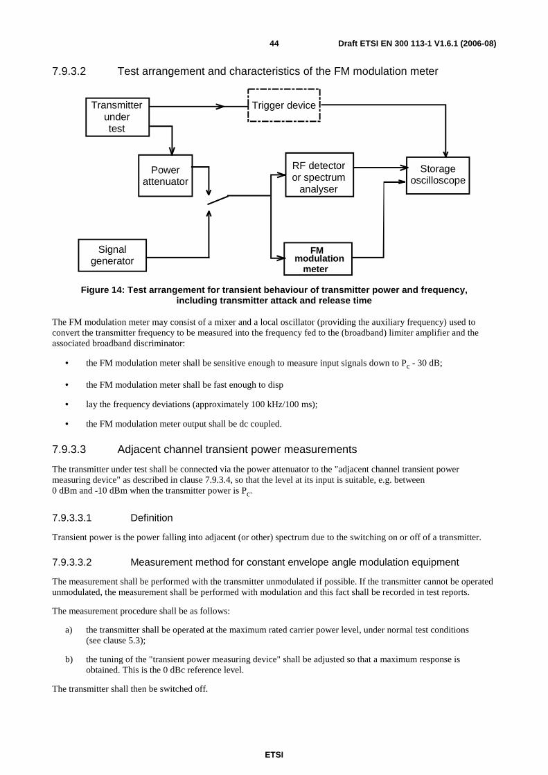
ETSI
Draft ETSI EN 300 113-1 V1.6.1 (2006-08) 44
7.9.3.2 Test arrangement and characteristics of the FM modulation meter
Powerattenuator
Storageoscilloscope
Trigger device
Signalgenerator
Transmitterundertest
RF detectoror spectrum
analyser
meter
FMmodulation
Figure 14: Test arrangement for transient behaviour of transmitter power and frequency, including transmitter attack and release time
The FM modulation meter may consist of a mixer and a local oscillator (providing the auxiliary frequency) used to convert the transmitter frequency to be measured into the frequency fed to the (broadband) limiter amplifier and the associated broadband discriminator:
• the FM modulation meter shall be sensitive enough to measure input signals down to Pc - 30 dB;
• the FM modulation meter shall be fast enough to disp
• lay the frequency deviations (approximately 100 kHz/100 ms);
• the FM modulation meter output shall be dc coupled.
7.9.3.3 Adjacent channel transient power measurements
The transmitter under test shall be connected via the power attenuator to the "adjacent channel transient power measuring device" as described in clause 7.9.3.4, so that the level at its input is suitable, e.g. between 0 dBm and -10 dBm when the transmitter power is Pc.
7.9.3.3.1 Definition
Transient power is the power falling into adjacent (or other) spectrum due to the switching on or off of a transmitter.
7.9.3.3.2 Measurement method for constant envelope angle modulation equipment
The measurement shall be performed with the transmitter unmodulated if possible. If the transmitter cannot be operated unmodulated, the measurement shall be performed with modulation and this fact shall be recorded in test reports.
The measurement procedure shall be as follows:
a) the transmitter shall be operated at the maximum rated carrier power level, under normal test conditions (see clause 5.3);
b) the tuning of the "transient power measuring device" shall be adjusted so that a maximum response is obtained. This is the 0 dBc reference level.
The transmitter shall then be switched off.

ETSI
Draft ETSI EN 300 113-1 V1.6.1 (2006-08) 45
c) the tuning of the "transient power measuring device" shall be adjusted away from the carrier so that its -6 dB response nearest to the transmitter carrier frequency is located at a displacement from the nominal carrier frequency as given in table 6;
Table 6: Frequency displacement
Channel separation (kHz) Displacement (kHz)
12,5 8,25 20 13 25 17
d) the transmitter shall be switched on;
e) the spectrum analyser shall be used to record the envelope of the transient power as a function of time (approximately 50 ms duration). The peak envelope transient power shall be noted in dBc;
f) the transmitter shall be switched off;
g) the spectrum analyser shall be used to record the envelope of the transient power as a function of time (approximately 50 ms duration). The peak envelope transient power shall be noted in dBc;
h) steps d) to g) shall be repeated five times and the highest response during "switch-on" and "switch-off" conditions shall be recorded;
i) steps c) to h) shall be repeated with the "transient power measuring device" tuned to the other side of the carrier;
j) the adjacent channel transient power during the attack and release times is the dBc value corresponding to the highest of the values recorded in step h).
This value shall be recorded.
NOTE: If burst duration is very short, more than one ramping-up and/or ramping-down phases can occur during the measurement period. This shall be taken into account but it does not affect the validity of the measurement. It just means that, in this case, steps d), e), f), g) and h) may be performed in a single operation.
7.9.3.3.3 Measurement method for non-constant envelope modulation equipment
The transmitter shall be modulated by the normal test signal, D-M5 or D-M7 as appropriate (see clause 6.3).
For constant envelope modulation schemes it is not required to apply modulation. The modulation used, if any, shall be recorded in the test report.
The measurement procedure shall be as follows:
a) the transmitter shall be operated at the maximum rated carrier power level, under normal test conditions (see clause 5.3);
b) the tuning of the "transient power measuring device" shall be adjusted so that a maximum response is obtained. This is the 0 dBc reference level;

ETSI
Draft ETSI EN 300 113-1 V1.6.1 (2006-08) 46
The transmitter shall then be switched off.
c) The tuning of the "transient power measuring device" shall be adjusted away from the carrier so that its -6 dB response nearest to the transmitter carrier frequency is located at a displacement from the nominal carrier frequency as given in table 7;
Table 7: Frequency displacements
Adjacent Channel Measurement
Channel separation (kHz) Displacement (kHz) 12,5 8,25 20 13 25 17
d) the transmitter shall be switched on;
e) the spectrum analyser shall be used to record the envelope of the transient power as a function of time (approximately 50 ms duration). The peak envelope transient power shall be noted in dBc;
f) the transmitter shall be switched off;
g) the spectrum analyser shall be used to record the envelope of the transient power as a function of time (approximately 50 ms duration). The peak envelope transient power shall be noted in dBc;
h) steps d) to g) shall be repeated five times and the highest response during "switch-on" and "switch-off" conditions shall be recorded;
i) steps c) to h) shall be repeated with the "transient power measuring device" tuned to the other side of the carrier;
j) steps c) to i) shall be repeated with the tuning of the "transient power measuring device "adjusted away from the centre of the channel so that its -6 dB response nearest to the transmitter channel centre frequency is located successively at displacements from the nominal carrier frequency as given in table 7;
k) the adjacent channel transient power during the attack and release times is the dBc value corresponding to the highest of the values recorded in step h).
This value shall be recorded.
NOTE: If burst duration is very short, more than one ramping-up and/or ramping-down phases can occur during the measurement period. This shall be taken into account but it does not affect the validity of the measurement. It just means that, in this case, steps d), e), f), g) and h) may be performed in a single operation.

ETSI
Draft ETSI EN 300 113-1 V1.6.1 (2006-08) 47
7.9.3.4 Characteristics of the adjacent channel transient power measuring device
Signalgenerator
Transmitterundertest
Powerattenuator
Adjacentchannel
filter
Spectrumanalyser
Mixer
Triggering
Figure 15: Adjacent channel transient power measuring device measurement arrangement
The adjacent channel transient power measuring device may be as follows:
• Mixer: 50 Ω balanced diode mixer; with an appropriate local oscillator level, for example +7 dBm;
• adjacent channel filter: matched to 50 Ω (annex B);
• spectrum analyser: 100 kHz bandwidth, peak detection, or power/time measurement provision.
7.9.4 Limits
Transients may occur very often in some types of equipment (e.g. packet data systems) and are a potential source of interference for equipment operating both in adjacent channels and much further away in the spectrum.
The effects of transients can be very different from case to case because there are a number of possible mechanisms relating to such phenomena. For that reason, the method of measurement provided in the present document is expected to capture events that may have a high probability of happening, but some other unacceptable effects of transients may require specific methods to be detected and measured.
The method and limits provided in the present document are therefore the result of a compromise between an acceptable level of confidence and an acceptable complexity of the measurement.
7.9.4.1 Time domain analysis of power and frequency
When appropriate, the plots of carrier power (conducted) and carrier frequency as a function of time, covering in an appropriate way the transients, shall be included in test reports.
At any time when the carrier power is above Pc - 30 dB, the carrier frequency shall remain within half a channel
separation (dfc) from the steady carrier frequency (Fc).
In case of equipment operating with channel separation of 12,5 kHz, the slopes of the plots "power as a function of time" corresponding to both attack and release times, shall be such that:
• tp ≥ 0,10 ms and td ≥ 0,10 ms, for attack and release time;
• between the Pc - 30 dB point and the Pc - 6 dB point, both in the case of attack and release time, the sign of the
slope shall not change.

ETSI
Draft ETSI EN 300 113-1 V1.6.1 (2006-08) 48
In case of equipment operating with channel separation of 20 kHz or 25 kHz, the slopes of the plots "power as a function of time" corresponding to both attack and release times, shall be such that:
• tp ≥ 0,05 ms and td ≥ 0,05 ms, for attack and release time;
• between the Pc- 30 dB point and the Pc- 6 dB point, both in the case of attack and release time, the sign of the
slope shall not change.
7.9.4.2 Adjacent channel transient power
7.9.4.2.1 Equipment measured as constant envelope angle modulation equipment
The transient power, in the adjacent channels shall not exceed a value of:
• 60,0 dB below the carrier power (conducted) of the transmitter in decibels relative to the carrier power (dBc) without the need to be below 2 µW (-27,0 dBm), for channel separations of 20 kHz and 25 kHz;
• 50,0 dB below the carrier power (conducted) of the transmitter (in dBc) without the need to be below 2 µW (-27,0 dBm), for a channel separation of 12,5 kHz.
7.9.4.2.2 Equipment measured as non-constant envelope modulation equipment
Figure 16 shows the position of adjacent and alternate channels with respect to the wanted channel.
fc
LowerAlternate
UpperAlternate
LowerAdjacent
UpperAdjacent
WantedChannel
Figure 16: Adjacent and alternate channel definitions
The transient power, in the adjacent channels shall not exceed a value of:
• 60,0 dB below the carrier power (conducted) of the transmitter in decibels relative to the carrier power (dBc) without the need to be below 2 µW (-27,0 dBm), for channel separations of 20 kHz and 25 kHz;
• 50,0 dB below the carrier power (conducted) of the transmitter (in dBc) without the need to be below 2 µW (-27,0 dBm), for a channel separation of 12,5 kHz.
The transient power, in the alternate channels shall not exceed a value of:
• 65,0 dB below the carrier power (conducted) of the transmitter in decibels relative to the carrier power (dBc) without the need to be below 2 µW (-27,0 dBm), for channel separations of 20 kHz and 25 kHz;
• 60,0 dB below the carrier power (conducted) of the transmitter (in dBc) without the need to be below 2 µW (-27,0 dBm), for a channel separation of 12,5 kHz.

ETSI
Draft ETSI EN 300 113-1 V1.6.1 (2006-08) 49
For measurements at 100 kHz and 1 MHz (from the wanted channel), the transient power shall not exceed a value:
• 65,0 dB below the carrier power (conducted) of the transmitter in decibels relative to the carrier power (dBc) without the need to be below 2 µW (-27,0 dBm), for channel separations of 20 kHz and 25 kHz;
• 60,0 dB below the carrier power (conducted) of the transmitter (in dBc) without the need to be below 2 µW (-27,0 dBm), for a channel separation of 12,5 kHz.
8 Methods of measurement for receiver parameters
8.1 Maximum usable sensitivity (digital, conducted)
8.1.1 Definition
The maximum usable sensitivity (data or messages, conducted) is the minimum level of signal (emf) at the receiver input, produced by a carrier at the nominal frequency of the receiver, modulated with the normal test signal (see clause 6.3), which will, without interference, produce after demodulation a data signal with a specified bit error ratio or a specified successful message ratio. The specified bit error ratio is 10-2. The specified successful message ratio is 80 %.
The equipment (transmission and/or reception ) under test shall be operated in its normal transmission mode (which may be continuous or discontinuous).
8.1.2 Method of measurement
8.1.2.1 Method of measurement with continuous bit streams
Signalgenerator
Receiverundertest
Bit errormeasuring
test set
Bit streamgenerator
(D-M2)
Figure 17: Measurement arrangement
The measurement procedure shall be as follows:
a) an input signal with a frequency equal to the nominal frequency of the receiver, modulated by the normal test signal D-M2 or D-M5, as appropriate (see clause 6.3), shall be applied to the receiver input terminals;
b) the bit pattern of the modulating signal shall be compared to the bit pattern obtained from the receiver after demodulation;
c) the emf of the input signal to the receiver is adjusted until the bit error ratio is 10-2 or better. (When the value of 10-2 cannot be reached exactly, this shall be taken into account in the evaluation of the measurement uncertainty (TR 100 028 [3]);
d) the maximum usable sensitivity is the emf of the input signal to the receiver.
This value shall be recorded.
e) the measurement shall be repeated under extreme test conditions (see clauses 5.4.1 and 5.4.2 applied simultaneously).

ETSI
Draft ETSI EN 300 113-1 V1.6.1 (2006-08) 50
8.1.2.2 Method of measurement with messages
Signalgenerator
Receiverundertest
Messagemeasuring
test set
Messagegenerator
Figure 18: Measurement arrangement
The measurement procedure shall be as follows:
a) an input signal with a frequency equal to the nominal frequency of the receiver, having normal test modulation (see clause 6.3), in accordance with the instructions of the manufacturer (and accepted by the testing laboratory), shall be applied to the receiver input terminals;
b) the level of this signal shall be such that a successful message ratio of less than 10 % is obtained;
c) the normal test signal (see clause 6.3) shall then be transmitted repeatedly whilst observing in each case whether or not a message is successfully received;
the level of the input signal shall be increased by 2 dB for each occasion that a message is not successfully received;
the procedure shall be continued until three consecutive messages are successfully received;
the level of the input signal shall then be noted;
d) the level of the input signal shall be reduced by 1 dB and the new value noted;
the normal test signal (see clause 6.3) shall then be transmitted 20 times. In each case, if a message is not successfully received the level of the input signal shall be increased by 1 dB and the new value noted;
if a message is successfully received, the level of the input signal shall not be changed until three consecutive messages have been successfully received. In this case, the level of the input signal shall be reduced by 1 dB and the new value noted;
no level of the input signal shall be noted unless preceded by a change in level;
the maximum usable sensitivity is the average of the values noted in steps c) and d) (which provides the level corresponding to the successful message ratio of 80 %).
This value shall be recorded.
e) the measurement shall be repeated under extreme test conditions (see clauses 5.4.1 and 5.4.2).
8.1.3 Limits
The maximum usable sensitivity shall not exceed an electromotive force (emf) of +3,0 dBµV under normal test conditions, and an emf of +9,0 dBµV under extreme test conditions.
8.2 Average usable sensitivity (digital, field strength) This measurement applies only to equipment without an external antenna connector.
8.2.1 Definition
For the definition see EN 300 390-1 [2], clause 9.1.

ETSI
Draft ETSI EN 300 113-1 V1.6.1 (2006-08) 51
8.2.2 Method of measurement
The equipment (transmission and/or reception ) under test shall be operated in its normal transmission mode (which may be continuous or discontinuous).
For the method of measurement see EN 300 390-1 [2], clause 9.1.
8.2.3 Limits
The limit(s) corresponding to this parameter can be found in clause 5.2.1 of EN 300 390-1 [2].
8.3 Level of the wanted signal for the degradation measurements (data or messages)
Degradation measurements are those measurements which are made on the receiver to establish the degradation of the performance of the receiver due to the presence of (an) unwanted (interfering) signal(s).
The level of the wanted signal for the degradation measurements, under normal test conditions (see clause 5.3), shall be an emf of +6 dBµV. It is 3 dB above the limit of the maximum usable sensitivity (data or messages, conducted).
8.4 Error behaviour at high input levels
8.4.1 Definition
The error behaviour (performance) at high input levels (noise free operation) is defined by the bit error ratio (continuous bit stream) or by the number of messages lost or corrupted when the level of the wanted signal is significantly above the maximum usable sensitivity.
The equipment (transmission and/or reception ) under test shall be operated in its normal transmission mode (which may be continuous or discontinuous).
8.4.2 Method of measurement
8.4.2.1 Method of measurement with continuous bit streams
Signalgenerator
Receiverundertest
Bit errormeasuring
test set
Bit streamgenerator
(D-M2)
Figure 19: Measurement arrangement
The measurement procedure shall be as follows:
a) an input signal with a frequency equal to the nominal frequency of the receiver, modulated by the normal test signal D-M2 or D-M5, as appropriate (see clause 6.3), shall be applied to the receiver input terminals;
b) the bit pattern of the modulating signal shall be compared to the bit pattern obtained from the receiver after demodulation;
c) the level of the input signal shall be adjusted to a level which is 30 dB above the level of the wanted signal for the degradation measurements (see clause 8.3);

ETSI
Draft ETSI EN 300 113-1 V1.6.1 (2006-08) 52
d) the number of errors that occur at the data output terminals or at a special measuring terminal of the receiver, during a period of 3 minutes, shall be counted.
This value shall be recorded.
e) the measurement shall be repeated with the level of the input signal of the receiver adjusted to a level which is 100 dB above the level of the wanted signal for the degradation measurements (see clause 8.3).
8.4.2.2 Method of measurement with messages
Signalgenerator
Receiverundertest
Messagemeasuring
test set
Messagegenerator
Figure 20: Measurement arrangement
The measurement procedure shall be as follows:
a) an input signal with a frequency equal to the nominal frequency of the receiver, having normal test modulation (see clause 6.3), in accordance with the instructions of the manufacturer (and accepted by the testing laboratory), shall be applied to the receiver input terminals;
b) the level of the input signal shall be adjusted to a level which is 30 dB above the level of the wanted signal for the degradation measurements (see clause 8.3);
c) the normal test signal (see clause 6.3) shall then be transmitted 100 times whilst observing in each case whether or not a message is successfully received;
d) the number of messages not successfully received shall be recorded;
e) the measurement shall be repeated with the input signal of the receiver at a level which is 100 dB above the wanted signal for the degradation measurements (see clause 8.3).
8.4.3 Limits
The bit error ratio (continuous bit streams) shall not exceed 10-4.
The number of messages not correctly received (lost or corrupted) shall not exceed 1.
8.5 Co-channel rejection
8.5.1 Definition
The co-channel rejection is a measure of the capability of the receiver to receive a wanted modulated signal without exceeding a given degradation due the presence of an unwanted modulated signal, both signals being at the nominal frequency of the receiver.
The equipment (transmission and/or reception ) under test shall be operated in its normal transmission mode (which may be continuous or discontinuous).

ETSI
Draft ETSI EN 300 113-1 V1.6.1 (2006-08) 53
8.5.2 Method of measurement
8.5.2.1 Method of measurement with continuous bit streams
Receiverundertest
Signalgenerator
A
Signalgenerator
B
CombinerBit error
measuringtest set
Figure 21: Measurement arrangement
The measurement procedure shall be as follows:
a) two signal generators, A and B, shall be connected to the receiver via a combining network;
the wanted signal, provided by signal generator A, shall be at the nominal frequency of the receiver and shall be modulated by the normal test signal D-M2 or D-M5, as appropriate (see clause 6.3);
the unwanted signal, provided by signal generator B, shall be modulated with signal A-M3 (see clause 6.3);
both input signals shall be at the nominal frequency of the receiver under test;
b) initially, signal generator B (unwanted signal) shall be switched off (maintaining the output impedance);
the level of the wanted signal from generator A shall be adjusted to a level which is 3 dB above the level of the limit of the maximum usable sensitivity (data or messages), at the receiver input terminals (i.e. 6 dB above 1 µV emf under normal test conditions);
c) signal generator B shall then be switched on, and the level of the unwanted signal adjusted until a bit error ratio of 10-1 or worse is obtained;
d) the normal test signal D-M2 shall be transmitted whilst observing the bit error ratio;
e) the level of the unwanted signal shall be reduced in steps of 1 dB until a bit error ratio of 10-2 or better is obtained. The level of the unwanted signal shall then be noted;
f) for each frequency of the unwanted signal, the co-channel rejection ratio shall be expressed as the ratio, in dB, of the level of the unwanted signal to the level of the wanted signal, at the receiver input.
This ratio shall be recorded.
g) the measurement shall be repeated for displacements of the unwanted signal of ±12 % of the channel separation;
h) the co-channel rejection ratio of the equipment under test shall be expressed as the lowest of the three values expressed in dB, calculated in step f);
the value of the co-channel rejection ratio, expressed in dB, is generally negative (therefore, for example, -12 dB is lower than -8 dB).

ETSI
Draft ETSI EN 300 113-1 V1.6.1 (2006-08) 54
8.5.2.2 Method of measurement with messages
Receiverundertest
Signalgenerator
A
Signalgenerator
B
CombinerMessage
measuringtest set
Figure 22: Measurement arrangement
The measurement procedure shall be as follows:
a) two signal generators, A and B, shall be connected to the receiver via a combining network;
the wanted signal, provided by signal generator A, shall be at the nominal frequency of the receiver and shall have normal test modulation (see clause 6.3);
the unwanted signal, provided by signal generator B, shall be modulated with signal A-M3 (see clause 6.3);
both input signals shall be at the nominal frequency of the receiver;
b) initially, signal generator B (unwanted signal) shall be switched off (maintaining the output impedance);
the level of the wanted signal from generator A shall be adjusted to a level which is 3 dB above the level of the limit of the maximum usable sensitivity (data or messages) at the receiver input terminals (i.e. 6 dB above 1 µV emf under normal test conditions);
c) signal generator B shall then be switched on, and the level of the unwanted signal adjusted until a successful message ratio of less than 10 % is obtained;
d) the normal test signal (see clause 6.3) shall then be transmitted repeatedly whilst observing in each case whether or not a message is successfully received;
the level of the unwanted signal shall be reduced by 2 dB for each occasion that a message is not successfully received;
the procedure shall be continued until three consecutive messages are successfully received. The level of the input signal shall then be noted;
e) the level of the unwanted signal shall be increased by 1 dB and the new value noted;
the normal test signal (see clause 6.3) shall then be transmitted 20 times. In each case, if a message is not successfully received the level of the unwanted signal shall be reduced by 1 dB and the new value noted;
if a message is successfully received, the level of the unwanted signal shall not be changed until three consecutive messages have been successfully received. In this case the unwanted signal shall be increased by 1 dB and the new value noted;
no level of the unwanted signal level shall be noted unless preceded by a change in level.;
the average of the values noted in steps d) and e) (which provides the level corresponding to the successful message ratio of 80 %) shall be noted;
f) for each frequency of the unwanted signal, the co-channel rejection ratio shall be expressed as the ratio, in dB, of the average level noted in step e) to the level of the wanted signal, at the receiver input.
This ratio shall be recorded.
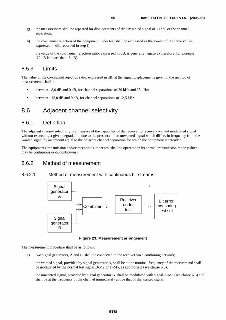
ETSI
Draft ETSI EN 300 113-1 V1.6.1 (2006-08) 55
g) the measurement shall be repeated for displacements of the unwanted signal of ±12 % of the channel separation;
h) the co-channel rejection of the equipment under test shall be expressed as the lowest of the three values expressed in dB, recorded in step f);
the value of the co-channel rejection ratio, expressed in dB, is generally negative (therefore, for example, -12 dB is lower than -8 dB).
8.5.3 Limits
The value of the co-channel rejection ratio, expressed in dB, at the signal displacements given in the method of measurement, shall be:
• between - 8,0 dB and 0 dB, for channel separations of 20 kHz and 25 kHz;
• between - 12,0 dB and 0 dB, for channel separations of 12,5 kHz.
8.6 Adjacent channel selectivity
8.6.1 Definition
The adjacent channel selectivity is a measure of the capability of the receiver to receive a wanted modulated signal without exceeding a given degradation due to the presence of an unwanted signal which differs in frequency from the wanted signal by an amount equal to the adjacent channel separation for which the equipment is intended.
The equipment (transmission and/or reception ) under test shall be operated in its normal transmission mode (which may be continuous or discontinuous).
8.6.2 Method of measurement
8.6.2.1 Method of measurement with continuous bit streams
Receiverundertest
Signalgenerator
A
Signalgenerator
B
CombinerBit error
measuringtest set
Figure 23: Measurement arrangement
The measurement procedure shall be as follows:
a) two signal generators, A and B, shall be connected to the receiver via a combining network;
the wanted signal, provided by signal generator A, shall be at the nominal frequency of the receiver and shall be modulated by the normal test signal D-M2 or D-M5, as appropriate (see clause 6.3);
the unwanted signal, provided by signal generator B, shall be modulated with signal A-M3 (see clause 6.3) and shall be at the frequency of the channel immediately above that of the wanted signal;

ETSI
Draft ETSI EN 300 113-1 V1.6.1 (2006-08) 56
b) initially, signal generator B (unwanted signal) shall be switched off (maintaining the output impedance);
the level of the wanted signal from generator A shall be adjusted to the level which is 3 dB above the level of the limit of the maximum usable sensitivity (data or messages), at the receiver input terminals (i.e. 6 dB above 1 µV emf under normal test conditions);
c) signal generator B shall then be switched on, and the level of the unwanted signal adjusted until a bit error ratio of 10-1 or worse is obtained;
d) the normal test signal D-M2 shall be transmitted whilst observing the bit error ratio;
e) the level of the unwanted signal shall be reduced in steps of 1 dB until a bit error ratio of 10-2 or better is obtained. The level of the unwanted signal shall then be noted;
f) for each adjacent channel, the selectivity shall be expressed as the ratio, in dB, of the level of the unwanted signal to the level of the wanted signal, at the receiver input.
This ratio shall be recorded.
g) the measurement shall be repeated with the unwanted signal at the frequency of the channel below that of the wanted signal;
h) the adjacent channel selectivity of the equipment under test shall be expressed as the lower of the two values measured in the upper and lower channels nearest to the receiving channel (see step f) above);
i) the measurement shall be repeated under extreme test conditions (see clauses 5.4.1 and 5.4.2 applied simultaneously), using the level of the wanted signal (data or messages), increased by 6 dB;
if analogue measurements according to EN 300 086-1 [1] have been made before, including adjacent channel selectivity under extreme test conditions, the adjacent channel selectivity (data or messages) shall be measured at normal test conditions only.
NOTE: This is a valid procedure, because the degradation of adjacent channel selectivity at extreme test conditions is known by the analogue measurement results.
8.6.2.2 Method of measurement with messages
Receiverundertest
Signalgenerator
A
Signalgenerator
B
CombinerMessage
measuringtest set
Figure 24: Measurement arrangement
The measurement procedure shall be as follows:
a) two signal generators, A and B, shall be connected to the receiver via a combining network;
the wanted signal, provided by signal generator A, shall be at the nominal frequency of the receiver and shall have normal test modulation (see clause 6.3);
the unwanted signal, provided by signal generator B, shall be modulated with signal A-M3 (see clause 6.3) and shall be at the frequency of the channel immediately above that of the wanted signal;

ETSI
Draft ETSI EN 300 113-1 V1.6.1 (2006-08) 57
b) initially, signal generator B (unwanted signal) shall be switched off (maintaining the output impedance);
the level of the wanted signal from generator A shall be adjusted to the level which is 3 dB above the level of the limit of the maximum usable sensitivity (data or messages), at the receiver input terminals (i.e. 6 dB above 1 µV emf under normal test conditions);
c) signal generator B shall then be switched on, and the level of the unwanted signal adjusted until a successful message ratio of less than 10 % is obtained;
d) the normal test signal (see clause 6.3) shall then be transmitted repeatedly whilst observing in each case whether or not a message is successfully received;
the level of the unwanted signal shall be reduced by 2 dB for each occasion that a message is not successfully received;
the procedure shall be continued until three consecutive messages are successfully received. The level of the input signal shall then be noted;
e) the level of the unwanted signal shall be increased by 1 dB and the new value noted;
the normal test signal (see clause 6.3) shall then be transmitted 20 times. In each case, if a message is not successfully received the level of the unwanted signal shall be reduced by 1 dB and the new value noted;
if a message is successfully received, the level of the unwanted signal shall not be changed until three consecutive messages have been successfully received. In this case the unwanted signal shall be increased by 1 dB and the new value noted;
no level of the unwanted signal shall be noted unless preceded by a change in level;
the average of the values noted in steps d) and e) (which provides the level corresponding to the successful message ratio of 80 %) shall be noted;
f) for each adjacent channel, the selectivity shall be expressed as the ratio, in dB, of the average level noted in step e) to the level of the wanted signal, at the receiver input.
This value shall be recorded.
g) the measurement shall be repeated with the unwanted signal at the frequency of the channel below that of the wanted signal;
h) the adjacent channel selectivity of the equipment under test shall be expressed as the lower of the two values measured in the upper and lower adjacent channel nearest to the receiving channel (see step f) above);
i) the measurement shall be repeated under extreme test conditions (see clauses 5.4.1 and 5.4.2 applied simultaneously), using the level of the wanted signal (data or messages), increased by 6 dB;
if analogue measurements according to EN 300 086-1 [1] have been made before, including adjacent channel selectivity under extreme test conditions, the adjacent channel selectivity (data or messages) shall be measured at normal test conditions only.
NOTE: This is a valid procedure because the degradation of adjacent channel selectivity at extreme test conditions is known by the analogue measurement results.
8.6.3 Limits
The adjacent channel selectivity for different channel separations shall not be less than the values given in table 8.
Table 8: Adjacent channel selectivity
Channel separation 12,5 kHz 20/25 kHz
normal test conditions 60,0 dB 70,0 dB extreme test conditions 50,0 dB 60,0 dB
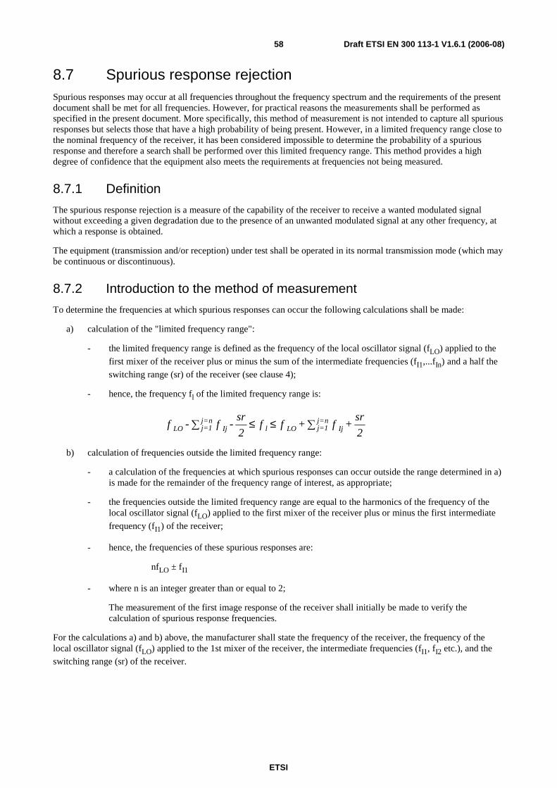
ETSI
Draft ETSI EN 300 113-1 V1.6.1 (2006-08) 58
8.7 Spurious response rejection Spurious responses may occur at all frequencies throughout the frequency spectrum and the requirements of the present document shall be met for all frequencies. However, for practical reasons the measurements shall be performed as specified in the present document. More specifically, this method of measurement is not intended to capture all spurious responses but selects those that have a high probability of being present. However, in a limited frequency range close to the nominal frequency of the receiver, it has been considered impossible to determine the probability of a spurious response and therefore a search shall be performed over this limited frequency range. This method provides a high degree of confidence that the equipment also meets the requirements at frequencies not being measured.
8.7.1 Definition
The spurious response rejection is a measure of the capability of the receiver to receive a wanted modulated signal without exceeding a given degradation due to the presence of an unwanted modulated signal at any other frequency, at which a response is obtained.
The equipment (transmission and/or reception) under test shall be operated in its normal transmission mode (which may be continuous or discontinuous).
8.7.2 Introduction to the method of measurement
To determine the frequencies at which spurious responses can occur the following calculations shall be made:
a) calculation of the "limited frequency range":
- the limited frequency range is defined as the frequency of the local oscillator signal (fLO) applied to the
first mixer of the receiver plus or minus the sum of the intermediate frequencies (fI1,...fIn) and a half the
switching range (sr) of the receiver (see clause 4);
- hence, the frequency fl of the limited frequency range is:
2
sr + f + f f
2
sr - f - f Ij
n=j1=jLOlIj
n=j1=jLO ∑≤≤∑
b) calculation of frequencies outside the limited frequency range:
- a calculation of the frequencies at which spurious responses can occur outside the range determined in a) is made for the remainder of the frequency range of interest, as appropriate;
- the frequencies outside the limited frequency range are equal to the harmonics of the frequency of the local oscillator signal (fLO) applied to the first mixer of the receiver plus or minus the first intermediate
frequency (fI1) of the receiver;
- hence, the frequencies of these spurious responses are:
nfLO ± fI1
- where n is an integer greater than or equal to 2;
The measurement of the first image response of the receiver shall initially be made to verify the calculation of spurious response frequencies.
For the calculations a) and b) above, the manufacturer shall state the frequency of the receiver, the frequency of the local oscillator signal (fLO) applied to the 1st mixer of the receiver, the intermediate frequencies (fI1, fI2 etc.), and the
switching range (sr) of the receiver.

ETSI
Draft ETSI EN 300 113-1 V1.6.1 (2006-08) 59
8.7.3 Method of search over the "limited frequency range"
Receiverundertest
Signalgenerator
A
Signalgenerator
B
Combiner
Bit error ormessage
measuringtest set
Figure 25: Measurement arrangement
The measurement procedure shall be as follows:
a) two signal generators, A and B, shall be connected to the receiver via a combining network;
the wanted signal, provided by signal generator A, shall be at the nominal frequency of the receiver and shall have the normal test signal or modulation (see clause 6.3);
the unwanted signal, provided by signal generator B, shall be modulated with signal A-M3 (see clause 6.3);
b) initially, signal generator B (unwanted signal) shall be switched off (maintaining the output impedance);
the level of the wanted signal from generator A shall be adjusted to the level which is 3 dB above the level of the limit of the maximum usable sensitivity (data or messages), at the receiver input terminals (i.e. 6 dB above 1 µV emf under normal test conditions);
in the case where a continuous bit stream is used, the bit error ratio of the receiver after demodulation shall be noted;
c) signal generator B shall then be switched on, and the level of the unwanted signal adjusted to 86 dBµV at the receiver input terminals;
the frequency of the unwanted signal generator shall be varied in increments of 5 kHz over the limited frequency range (see clause 8.7.2 a)) and over the frequencies in accordance with the calculations outside of this frequency range (see clause 8.7.2 b);
d) the frequency of any spurious response detected (e.g. by an increase in the previously noted bit error ratio) during the search shall be recorded for use in the measurements in accordance with clauses 8.7.4 and 8.7.5;
e) in the case where operation using a continuous bit stream is not possible a similar method shall be used. In such case, instead of identifying a spurious response by noting an increase in the bit error ratio, spurious responses shall be identified by a degradation of the successful message ratio.
8.7.4 Method of measurement with continuous bit streams
The measurement shall be performed as follows, using the measurement arrangement of figure 25 in clause 8.7.3:
a) two signals generators, A and B, shall be connected to the receiver via a combining network;
the wanted signal, provided by signal generator A, shall be at the nominal frequency of the receiver and shall be modulated by the normal test signal D-M2 or D-M5, as appropriate (see clause 6.3);
the unwanted signal, provided by signal generator B, shall be modulated with a frequency of 400 Hz and with a deviation of 12 % of the channel separation (A-M3) (see clause 6.3), and shall be at the frequency of that spurious response being considered;

ETSI
Draft ETSI EN 300 113-1 V1.6.1 (2006-08) 60
b) initially, signal generator B (unwanted signal) shall be switched off (maintaining the output impedance);
the level of the wanted signal from generator A shall be adjusted to the level which is 3 dB above the level of the limit of the maximum usable sensitivity (data or messages), at the receiver input terminals (i.e. 6 dB above 1 µV emf under normal test conditions);
c) signal generator B shall then be switched on, and the level of the unwanted signal adjusted until a bit error ratio of 10-1 or worse is obtained;
d) the normal test signal D-M2 shall be transmitted whilst observing the bit error ratio;
e) the level of the unwanted signal shall be reduced in steps of 1 dB until a bit error ratio of 10-2 or better is obtained. The level of the unwanted signal shall then be noted;
f) for each frequency, the spurious response rejection shall be expressed as the ratio, in dB, of the level of the unwanted signal to the level of the wanted signal, at the receiver input.
This ratio shall be recorded.
g) the measurement shall be repeated at all spurious response frequencies found during the search over the "limited frequency range" (see clause 8.7.2 a)) and at frequencies calculated for the remainder of the spurious response frequencies (see clause 8.7.2 b)) in the frequency range from fRx/3,2 or 30 MHz, whichever is higher,
to 3,2 × fRx, where fRx is the nominal frequency of the receiver;
h) the spurious response rejection of the equipment under test shall be expressed as the lowest value recorded in step f).
8.7.5 Method of measurement with messages
The measurement shall be performed as follows, using the measurement arrangement of figure 25 in clause 8.7.3:
a) two signal generators, A and B, shall be connected to the receiver via a combining network
the wanted signal, provided by signal generator A, shall be at the nominal frequency of the receiver and shall have normal test modulation (see clause 6.3);
the unwanted signal, provided by signal generator B, shall be modulated with a frequency of 400 Hz and with a deviation of 12 % of the channel separation (A-M3) (see clause 6.3), and shall be at the frequency of that spurious response being considered;
b) initially, signal generator B (unwanted signal) shall be switched off (maintaining the output impedance);
the level of the wanted signal from generator A shall be adjusted to the level which is 3 dB above the level of the limit of the maximum usable sensitivity (data or messages), at the receiver input terminals (i.e. 6 dB above 1 µV emf under normal test conditions);
c) signal generator B shall then be switched on, and the level of the unwanted signal adjusted until a successful message ratio of less than 10 % is obtained;
d) the normal test signal (see clause 6.3) shall then be transmitted repeatedly whilst observing in each case whether or not a message is successfully received;
the level of the unwanted signal shall be reduced by 2 dB for each occasion that a message is not successfully received;
the procedure shall be continued until three consecutive messages are successfully received. The level of the input signal shall then be noted;

ETSI
Draft ETSI EN 300 113-1 V1.6.1 (2006-08) 61
e) the level of the unwanted signal shall be increased by 1 dB and the new value noted;
the normal test signal (see clause 6.3) shall then be transmitted 20 times. In each case, if a message is not successfully received the level of the unwanted signal shall be reduced by 1 dB and the new value noted;
if a message is successfully received, the level of the unwanted signal shall not be changed until three consecutive messages have been successfully received. In this case the unwanted signal shall be increased by 1 dB and the new value noted;
no level of the unwanted signal shall be noted unless preceded by a change in level;
the average of the values noted in steps d) and e) (which provides the level corresponding to the successful message ratio of 80 % shall be noted;
f) for each frequency, the spurious response rejection shall be expressed as the ratio, in dB, of the level of the unwanted signal to the level of the wanted signal, at the receiver input.
This ratio shall be recorded.
g) the measurement shall be repeated at all spurious response frequencies found during the search over the limited frequency range, (see clause 8.7.2 a)) and at frequencies calculated for the remainder of the spurious response frequencies (see clause 8.7.2, b)) in the frequency range from fRx/3,2 or 30 MHz, whichever is
higher, to 3,2 × fRx, where fRx is the nominal frequency of the receiver;
h) the spurious response rejection of the equipment under test shall be expressed as the lowest value recorded in step f).
8.7.6 Limits
At any frequency separated from the nominal frequency of the receiver by two channels or more, the spurious response rejection shall not be less than 70,0 dB.
8.8 Intermodulation response rejection
8.8.1 Definition
The intermodulation response rejection is a measure of the capability of the receiver to receive a wanted modulated signal, without exceeding a given degradation due to the presence of two or more unwanted signals with a specific frequency relationship to the wanted signal frequency.
The equipment (transmission and/or reception ) under test shall be operated in its normal transmission mode (which may be continuous or discontinuous).

ETSI
Draft ETSI EN 300 113-1 V1.6.1 (2006-08) 62
8.8.2 Method of measurement
8.8.2.1 Method of measurement with continuous bit streams
Receiverundertest
Signalgenerator
A
Signalgenerator
C
CombinerBit error
measuringtest set
Signalgenerator
B
Figure 26: Measurement arrangement
The measurement procedure shall be as follows:
a) three signal generators, A, B and C, shall be connected to the receiver via a combining network:
- the wanted signal, provided by signal generator A, shall be at the nominal frequency of the receiver and shall be modulated by the normal test signal D-M2 or D-M5, as appropriate (see clause 6.3);
- the first unwanted signal, provided by signal generator B, shall be unmodulated and adjusted to a frequency 50 kHz above the nominal frequency of the receiver;
- the second unwanted signal, provided by signal generator C, shall be modulated with signal A-M3 (see clause 6.3) and adjusted to a frequency 100 kHz above the nominal frequency of the receiver;
b) initially, signal generators B and C (unwanted signals) shall be switched off (maintaining the output impedance);
the level of the wanted signal from generator A shall be adjusted to the level which is 3 dB above the level of the limit of the maximum usable sensitivity (data or messages), at the receiver input terminals (i.e. 6 dB above 1 µV emf under normal test conditions);
c) signal generators B and C shall then be switched on; the levels of the two unwanted signals shall be maintained equal and shall be adjusted until a bit error ratio of 10-1 or worse is obtained;
d) the normal test signal D-M2 or D-M5, as appropriate shall then be transmitted whilst observing the bit error ratio;
e) the level of the unwanted signals shall be reduced in steps of 1 dB until a bit error ratio of 10-2 or better is obtained. The level of the unwanted signals shall then be noted;
f) for each configuration of the unwanted signals, the intermodulation response rejection shall be expressed as the ratio, in dB, of the level of the unwanted signals to the level of the wanted signal, at the receiver input.
This ratio shall be recorded.
g) the measurement shall be repeated with the unwanted signal generator B at the frequency 50 kHz below that of the wanted signal and the frequency of the unwanted signal generator C at the frequency 100 kHz below that of the wanted signal;
h) the intermodulation response rejection of the equipment under test shall be expressed as the lower of the two values recorded in step f).

ETSI
Draft ETSI EN 300 113-1 V1.6.1 (2006-08) 63
8.8.2.2 Method of measurement with messages
Receiverundertest
Signalgenerator
A
Signalgenerator
C
CombinerMessage
measuringtest set
Signalgenerator
B
Figure 27: Measurement arrangement
The measurement procedure shall be as follows:
a) three signal generators, A, B and C, shall be connected to the receiver via a combining network:
- the wanted signal, provided by signal generator A, shall be at the nominal frequency of the receiver and shall have normal test modulation (see clause 6.3);
- The first unwanted signal, provided by signal generator B, shall be unmodulated and adjusted to a frequency 50 kHz above the nominal frequency of the receiver;
- The second unwanted signal, provided by signal generator C, shall be modulated with signal A-M3 (see clause 6.3) and adjusted to a frequency 100 kHz above the nominal frequency of the receiver;
b) initially, signal generators B and C (unwanted signals) shall be switched off (maintaining the output impedance);
the level of the wanted signal from generator A shall be adjusted to the level which is 3 dB above the level of the limit of the maximum usable sensitivity (data or messages), at the receiver input terminals (i.e. 6 dB above 1 µV emf under normal test conditions);
c) signal generators B and C shall then be switched on; the levels of the two unwanted signals shall be maintained equal and shall be adjusted until a successful message ratio of less than 10 % is obtained;
d) the normal test signal (see clause 6.3) shall then be transmitted repeatedly whilst observing in each case whether or not a message is successfully received;
the levels of the unwanted signals shall be reduced by 2 dB for each occasion that a message is not successfully received;
the procedure shall be continued until three consecutive messages are successfully received. The level of the input signals shall then be noted;

ETSI
Draft ETSI EN 300 113-1 V1.6.1 (2006-08) 64
e) the level of the unwanted signals shall be increased by 1 dB and the new value noted;
the normal test signal (see clause 6.3) shall then be transmitted 20 times. In each case, if a message is not successfully received the level of the unwanted signals shall be reduced by 1 dB and the new value noted;
if a message is successfully received, the level of the unwanted signals shall not be changed until three consecutive messages have been successfully received. In this case the unwanted signals shall be increased by 1 dB and the new value noted;
no level of the unwanted signals shall be noted unless preceded by a change in level;
the average of the values noted in steps d) and e) (which provides the level corresponding to the successful message ratio of 80 %) shall be noted;
f) for each configuration of the unwanted signals, the intermodulation response rejection shall be expressed as the ratio, in dB, of the average level noted in step e) to the level of the wanted signal, at the receiver input.
This ratio shall be recorded.
g) the measurement shall be repeated with the unwanted signal generator B at the frequency 50 kHz below that of the wanted signal and the frequency of the unwanted signal generator C at the frequency 100 kHz below that of the wanted signal;
h) the intermodulation response rejection of the equipment under test shall be expressed as the lower of the two values recorded in step f).
8.8.3 Limits
The intermodulation response rejection ratio shall not be less than 70,0 dB for base station equipment and 65,0 dB for mobile and hand portable equipment.
8.9 Blocking or desensitization
8.9.1 Definition
Blocking is a measure of the capability of the receiver to receive a wanted modulated signal without exceeding a given degradation due to the presence of an unwanted input signal at any frequencies other than those of the spurious responses or the adjacent channels.
The equipment (transmission and/or reception ) under test shall be operated in its normal transmission mode (which may be continuous or discontinuous).
8.9.2 Method of measurement
8.9.2.1 Method of measurement with continuous bit streams
Receiverundertest
Signalgenerator
A
Signalgenerator
B
CombinerBit error
measuringtest set
Figure 28: Measurement arrangement

ETSI
Draft ETSI EN 300 113-1 V1.6.1 (2006-08) 65
The measurement procedure shall be as follows:
a) two signal generators, A and B, shall be connected to the receiver via a combining network :
- The wanted signal, provided by signal generator A, shall be at the nominal frequency of the receiver and shall be modulated by the normal test signal D-M2 or D-M5, as appropriate (see clause 6.3);
- The unwanted signal, provided by signal generator B, shall be unmodulated and shall be at a frequency from 1 MHz to 10 MHz away from the nominal frequency of the receiver;
for practical reasons the measurements shall be carried out at frequencies of the unwanted signal at approximately ±1 MHz, ±2 MHz, ±5 MHz and ±10 MHz, avoiding those frequencies at which spurious responses could occur (see clause 8.7);
b) initially, signal generator B (unwanted signal) shall be switched off (maintaining the output impedance);
the level of the wanted signal from generator A shall be adjusted to the level which is 3 dB above the level of the limit of the maximum usable sensitivity (data or messages), at the receiver input terminals (i.e. 6 dB above 1 µV emf under normal test conditions);
c) signal generator B shall then be switched on, and the level of the unwanted signal adjusted until a bit error ratio of 10-1 or worse is obtained;
d) the normal test signal D-M2 or D-M5, as appropriate shall be transmitted whilst observing the bit error ratio;
e) the level of the unwanted signal shall be reduced in steps of 1 dB until a bit error ratio of 10-2 or better is obtained. The level of the unwanted signal shall then be noted;
f) for each frequency, the blocking or desensitization shall be expressed as the ratio, in dB, of the level of the unwanted signal to the level of the wanted signal, at the receiver input.
This ratio shall be recorded.
g) the measurement shall be repeated for all the frequencies defined in step a);
h) the blocking or desensitization of the equipment under test shall be expressed as the lowest of the values recorded in step f).
8.9.2.2 Method of measurement with messages
Receiverundertest
Signalgenerator
A
Signalgenerator
B
CombinerMessage
measuringtest set
Figure 29: Measurement arrangement

ETSI
Draft ETSI EN 300 113-1 V1.6.1 (2006-08) 66
The measurement procedure shall be as follows:
a) two signal generators, A and B, shall be connected to the receiver via a combining network:
- the wanted signal, provided by signal generator A, shall be at the nominal frequency of the receiver and shall have normal test modulation (see clause 6.3);
- the unwanted signal, provided by signal generator B, shall be unmodulated and shall be at a frequency from 1 MHz to 10 MHz away from the nominal frequency of the receiver;
for practical reasons the measurements shall be carried out at frequencies of the unwanted signal at approximately ±1 MHz, ±2 MHz, ±5 MHz and ±10 MHz, avoiding those frequencies at which spurious responses could occur (see clause 8.7);
b) initially, signal generator B (unwanted signal) shall be switched off (maintaining the output impedance);
the level of the wanted signal from generator A shall be adjusted to the level which is 3 dB above the level of the limit of the maximum usable sensitivity (data or messages) at the receiver input terminals (i.e. 6 dB above 1 µV emf under normal test conditions);
c) signal generator B shall then be switched on, and the level of the unwanted signal adjusted until a successful message ratio of less than 10 % is obtained;
d) the normal test signal (see clause 6.3) shall then be transmitted repeatedly whilst observing in each case whether or not a message is successfully received;
the level of the unwanted signal shall be reduced by 2 dB for each occasion that a message is not successfully received;
the procedure shall be continued until three consecutive messages are successfully received. The level of the input signal shall then be noted;
e) the level of the unwanted signal shall be increased by 1 dB and the new value noted;
the normal test signal (see clause 6.3) shall then be transmitted 20 times. In each case, if a message is not successfully received the level of the unwanted signal shall be reduced by 1 dB and the new value noted;
if a message is successfully received, the level of the unwanted signals shall not be changed until three consecutive messages have been successfully received. In this case the unwanted signal shall be increased by 1 dB and the new value noted;
no level of the unwanted signal shall be noted unless preceded by a change in level;
the average of the values noted in steps d) and e) (which provides the level corresponding to the successful message ratio of 80 %) shall be noted;
f) for each frequency, the blocking or desensitization shall be expressed as the ratio, in dB, of the level of the unwanted signal to the level of the wanted signal, at the receiver input.
This ratio shall be recorded.
g) the measurement shall be repeated for all the frequencies defined in step a);
h) the blocking or desensitization of the equipment under test shall be expressed as the lowest of the values recorded in step f).

ETSI
Draft ETSI EN 300 113-1 V1.6.1 (2006-08) 67
8.9.3 Limits
The blocking ratio for any frequency within the specified ranges shall not be less than 84,0 dB, except at frequencies on which spurious responses are found.
8.10 Spurious radiations
8.10.1 Definition
Spurious radiations from the receiver are emissions at any frequency, radiated by the equipment and its antenna.
The level of spurious radiations shall be measured by:
either:
a) their power level in a specified load (conducted spurious emission); and
b) their effective radiated power when radiated by the cabinet and structure of the equipment (cabinet radiation); or
c) their effective radiated power when radiated by the cabinet and by the integral antenna, in the case of hand portable equipment fitted with such an antenna and no external RF connector.
8.10.2 Method of measuring the power level
Coupling deviceor attenuator
if needed
Spectrum analyzeror selectivevoltmeter
Receiverundertest
Figure 30: Measurement arrangement
This method applies only to equipment having an external antenna connector. Spurious radiations shall be measured as the power level of any discrete signal at the input terminals of the receiver. The receiver input terminals are connected to a spectrum analyser or selective Voltmeter having an input impedance of 50 Ω and the receiver is switched on.
If the detecting device is not calibrated in terms of power input, the level of any detected components shall be determined by a substitution method using a signal generator.
The measurements shall extend, for equipment operating on frequencies not exceeding 470 MHz, over the frequency range of 9 kHz to 4 GHz, and in addition shall be repeated over the frequency range 4 GHz to 12,75 GHz for equipment operating on frequencies above 470 MHz.

ETSI
Draft ETSI EN 300 113-1 V1.6.1 (2006-08) 68
8.10.3 Method of measuring the effective radiated power
1
Test site
2
3
1) Receiver under test 2) Test antenna 3) Spectrum analyser or selective Voltmeter (test receiver)
Figure 31: Measurement arrangement
The measurement procedure shall be as follows:
a) on a test site, fulfilling the requirements of annex A, the sample shall be placed at the specified height on the non-conducting support;
- the receiver shall be operated from a power source via a radio frequency filter to avoid radiation from the power leads;
b) the receiver shall be connected:
- to an artificial antenna (see clause 6.7) for equipment having an external antenna connector; or
- to the integral antenna;
c) radiation of any spurious components shall be detected by the test antenna and receiver, over the frequency range 30 MHz to 4 GHz;

ETSI
Draft ETSI EN 300 113-1 V1.6.1 (2006-08) 69
1 4
Test site
2 3
1) Signal generator 2) Substitution antenna 3) Test antenna 4) Spectrum analyser or selective Voltmeter (test receiver)
Figure 32: Measurement arrangement
d) at each frequency at which a component is detected, the sample shall be rotated to obtain maximum response and the effective radiated power of that component determined by a substitution measurement, using the measurement arrangement of figure 32;
the value of the effective radiated power of that component shall be recorded;
e) the measurement shall be repeated with the test antenna in the orthogonal polarization plane.
8.10.4 Limits
The power of any spurious radiation shall not exceed the values given in tables 9 and 10.
Table 9: Conducted components
Frequency range Limit 9 kHz to 1 GHz 2,0 nW (-57 dBm)
above 1 GHz to 4 GHz, or above 1 GHz to 12,75 GHz
20,0 nW (-47 dBm)
Table 10: Radiated components
Frequency range Limit 30 MHz to 1 GHz 2,0 nW (-57 dBm)
above 1 GHz to 4 GHz 20,0 nW (-47 dBm)

ETSI
Draft ETSI EN 300 113-1 V1.6.1 (2006-08) 70
In the case of radiated measurements for hand portable stations the following conditions apply:
• for equipment having an external antenna socket, an artificial load shall be connected to the socket during the test;
• for equipment having no external antenna socket, the normal integral antenna shall be used.
9 Duplex operation If the equipment is designed for duplex operation, the following additional measurements shall be carried out to ensure satisfactory duplex operation.
Equipment made available for such measurements shall be fitted with a duplex filter.
Duplex measurements shall be carried out on a single pair of frequencies only, as specified by the manufacturer (in consultation with the appropriate testing laboratory (if appropriate)).
Measurement for Duplex operation shall be carried out when, and only when, the equipment under test, either operating in continuous or discontinuous mode of operation, is transmitting and receiving signals simultaneously at the antenna(s).
For all measurements for Duplex operation the equipment (transmission and reception ) shall be operated in its normal transmission mode (which may be continuous or discontinuous).
9.1 Receiver desensitization (with simultaneous transmission and reception)
9.1.1 Definition
The desensitization is the degradation of the sensitivity of the receiver resulting from the transfer of power from the transmitter to the receiver due to coupling effects. It is expressed as the difference in dB between the maximum usable sensitivity levels (data or messages, conducted), with and without simultaneous transmissions.
9.1.2 Desensitization measured with continuous bit streams
9.1.2.1 Method of measurement when the equipment has a duplex filter
Signalgenerator
Bit errormeasuring
test set
Bit streamgenerator
(D-M2)
Artificialantenna
and coupler
Duplexfilter
Transmitter
Receiver
Bit streamgenerator(D-M2')
Figure 33: Measurement arrangement

ETSI
Draft ETSI EN 300 113-1 V1.6.1 (2006-08) 71
The measurement procedure shall be as follows:
a) the antenna terminal of the equipment comprising of the receiver, transmitter and duplex filter, shall be connected through a coupling device to the artificial antenna specified in clause 6.7;
a signal generator modulated by the normal test signal D-M2 or D-M5, as appropriate (see clause 6.3), shall be connected to the coupling device so that it does not affect the impedance matching and does not generate intermodulation products which could impair the results of the measurement;
b) the transmitter shall be brought into operation at the carrier output power as defined in clause 7.2, modulated by the normal test signal D-M2' or D-M5', as appropriate (see clause 6.3);
the receiver sensitivity (data, conducted) shall then be measured in accordance with clause 8.1.2;
c) the output level of the signal generator shall be noted as C in dB relative to an emf of 1 µV;
d) the transmitter shall then be switched off and the receiver sensitivity (data, conducted) is measured again;
e) the output level of the signal generator shall be noted as D in dB relative to an emf of 1 µV;
f) the desensitization is the difference between the values of C and D in dB.
9.1.2.2 Method of measurement when the equipment has to operate with two antennas
Signalgenerator
Bit errormeasuring
test set
Bit streamgenerator
(D-M2)
CombinerTransmitter
Receiver
Bit streamgenerator(D-M2')
Powerattenuator
Figure 34: Measurement arrangement
The measurement procedure shall be as follows:
a) the transmitter shall be connected to a power attenuator (in order to dissipate the nominal RF output power of the transmitter) the rating of which shall be declared by the manufacturer;
the attenuator output shall be connected to the receiver input by means of a coupling device and a filter, if the latter is part of the standard equipment. The total attenuation between transmitter and receiver shall be 30 dB;
a signal generator modulated by the normal test signal D-M2 or D-M5, as appropriate (see clause 6.3) shall be connected to the coupling device in such a way as not to affect the impedance matching and does not generate intermodulation products which could impair the results of the measurement;
b) the transmitter shall be brought into operation with an output power as defined in clause 7.2, modulated by the normal test signal D-M2' or D-M5', as appropriate (see clause 6.3);
the receiver sensitivity (data, conducted) shall then be measured in accordance with clause 8.1.2;

ETSI
Draft ETSI EN 300 113-1 V1.6.1 (2006-08) 72
c) the output level of the signal generator shall be noted as C in dB relative to an emf of 1 µV;
d) the transmitter shall then be switched off and the receiver sensitivity (data, conducted) measured again;
e) the output level of the signal generator shall be noted as D in dB relative to an emf of 1 µV;
f) the desensitization is the difference between the values of C and D in dB.
9.1.3 Desensitization measured with messages
9.1.3.1 Method of measurement when the equipment has a duplex filter
Signalgenerator
Messagemeasuring
test set
Messagegenerator
Artificialantenna
and coupler
Duplexfilter
Transmitter
Receiver
Messagegenerator
(D-M4)
Figure 35: Measurement arrangement
The measurement procedure shall be as follows:
a) the antenna terminal of the equipment comprising of the receiver, transmitter and duplex filter, shall be connected through a coupling device to the artificial antenna specified in clause 6.7;
a signal generator having normal test modulation (see clause 6.3) shall be connected to the coupling device so that it does not affect the impedance matching and does not generate intermodulation products which could impair the results of the measurement;
b) the transmitter shall be brought into operation with an output power as defined in clause 7.2, and shall be modulated by the normal test signal D-M4 or D-M7, as appropriate (see clause 6.3), using a message different from the message used in step a);
the receiver sensitivity (messages, conducted) shall then be measured in accordance with clause 8.1.2;
c) the output level of the signal generator shall be noted as C in dB relative to an emf of 1 µV;
d) the transmitter shall then be switched off and the receiver sensitivity (messages, conducted) measured again;
e) the output level of the signal generator shall be noted as D in dB relative to an emf of 1 µV;
f) the desensitization is the difference between the values of C and D in dB.
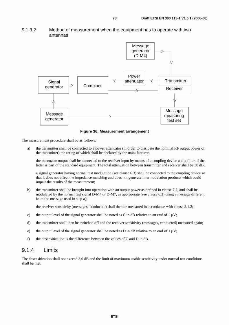
ETSI
Draft ETSI EN 300 113-1 V1.6.1 (2006-08) 73
9.1.3.2 Method of measurement when the equipment has to operate with two antennas
Signalgenerator
Messagemeasuring
test set
Messagegenerator
CombinerTransmitter
Receiver
Messagegenerator
(D-M4)
Powerattenuator
Figure 36: Measurement arrangement
The measurement procedure shall be as follows:
a) the transmitter shall be connected to a power attenuator (in order to dissipate the nominal RF output power of the transmitter) the rating of which shall be declared by the manufacturer;
the attenuator output shall be connected to the receiver input by means of a coupling device and a filter, if the latter is part of the standard equipment. The total attenuation between transmitter and receiver shall be 30 dB;
a signal generator having normal test modulation (see clause 6.3) shall be connected to the coupling device so that it does not affect the impedance matching and does not generate intermodulation products which could impair the results of the measurement;
b) the transmitter shall be brought into operation with an output power as defined in clause 7.2, and shall be modulated by the normal test signal D-M4 or D-M7, as appropriate (see clause 6.3) using a message different from the message used in step a);
the receiver sensitivity (messages, conducted) shall then be measured in accordance with clause 8.1.2;
c) the output level of the signal generator shall be noted as C in dB relative to an emf of 1 µV;
d) the transmitter shall then be switched off and the receiver sensitivity (messages, conducted) measured again;
e) the output level of the signal generator shall be noted as D in dB relative to an emf of 1 µV;
f) the desensitization is the difference between the values of C and D in dB.
9.1.4 Limits
The desensitization shall not exceed 3,0 dB and the limit of maximum usable sensitivity under normal test conditions shall be met.
ETSI
Draft ETSI EN 300 113-1 V1.6.1 (2006-08) 74
9.2 Receiver spurious response rejection (with simultaneous transmission and reception)
9.2.1 Definition
The spurious response rejection, under duplex operation, is a measure of the capability of the receiver to achieve a specific spurious response rejection ratio when receiving a wanted modulated signal in the presence of:
a) an unwanted signal at any other frequency, at which a response may be obtained; and
b) the unmodulated signal of the transmitter operating at duplex frequency distance, at the rated output power and attenuated by the duplex filter or by the distance between the antennas.
9.2.2 Method of measurement
The receiver spurious response rejection under duplex operation shall be measured as specified in clause 8.7 with the measurement arrangement described in clauses 9.1.2 or 9.1.3, except that the transmitter shall be unmodulated. The transmitter shall be operated at the carrier output power as defined in clause 7.2.
The measurement shall be performed around frequencies fm derived from the expressions:
(p)ft + (q)fm = fr and fm = (n)ft ± fI1;
where:
• ft is the transmitter frequency
• fr is the receiver frequency
and
• fI1 is the first IF of the receiver
• n = ≥2.
Particular attention should be made to the following values:
(p) = -1, (q) = 2 and (p) = 2, (q) = -1.
It should be noted that the method of measurement described may cause errors at certain frequencies due to the effect of signal generator intermodulation. To overcome such errors, a band stop filter at the transmitting frequency may be used, in conjunction with the signal generator combining network.
9.2.3 Limits
At any frequency separated from the nominal frequency of the receiver by two channels or more, the spurious response rejection ratio shall be greater than 67,0 dB.

ETSI
Draft ETSI EN 300 113-1 V1.6.1 (2006-08) 75
10 Measurement uncertainty The interpretation of the results recorded in the test report for the measurements described in the present document shall be as follows:
- the measured value related to the corresponding limit shall be used to decide whether an equipment meets the requirements of the present document;
- the value of the measurement uncertainty for the measurement of each parameter shall be separately included in the test report;
- the value of the measurement uncertainty should be, for each measurement, equal to or lower than the figures in table 11.
Table 11: Absolute measurement uncertainties: maximum values
Parameter Uncertainty Radio Frequency ±1 x 10⁻⁷ RF Power (up to 160 W) ±0,75 dB Radiated RF power ±6 dB Adjacent channel power ±5 dB Conducted spurious emission of transmitter valid up to 12,75 GHz
±4 dB
Conducted spurious emission of receiver, valid up to 12,75 GHz
±7 dB
Two-signal measurement, valid up to 4 GHz ±4 dB Three-signal measurement ±3 dB Radiated emission of the transmitter, valid up to 4 GHz
±6 dB
Radiated emission of receiver, valid up to 4 GHz
±6 dB
Transmitter attack time ±20 % Transmitter release time ±20 % Transmitter transient frequency (frequency difference)
±250 Hz
Transmitter intermodulation ±3 dB Receiver desensitization (duplex operation) ±0,5 dB Temperature ±1° K Humidity ±10 % NOTE: Valid up to 1 GHz for the RF parameters unless otherwise stated.
For the test methods, according to the present document, the measurement uncertainty figures shall be calculated in accordance with TR 100 028 [3] and shall correspond to an expansion factor (coverage factor) k = 1,96 or k = 2 (which provide confidence levels of respectively 95 % and 95,45 % in the case where the distributions characterizing the actual measurement uncertainties are normal (Gaussian).
Table 11 is based on such expansion factors.
The particular expansion factor used for the evaluation of the measurement uncertainty shall be stated.
TR 102 273 [4] provides further information concerning the usage of test sites.

ETSI
Draft ETSI EN 300 113-1 V1.6.1 (2006-08) 76
Annex A (normative): Radiated measurement
A.1 Test sites and general arrangements for measurements involving the use of radiated fields
This annex introduces three most commonly available test sites, an Anechoic Chamber, an Anechoic Chamber with a ground plane and an Open Area Test Site (OATS), which may be used for radiated tests. These test sites are generally referred to as free field test sites. Both absolute and relative measurements can be performed in these sites. Where absolute measurements are to be carried out, the chamber should be verified. A detailed verification procedure is described in TR 102 273 [4] relevant parts 2, 3 and 4.
NOTE: To ensure reproducibility and traceability of radiated measurements only these test sites should be used in measurements in accordance with the present document.
A.1.1 Anechoic chamber An anechoic chamber is an enclosure, usually shielded, whose internal walls, floor and ceiling are covered with radio absorbing material, normally of the pyramidal urethane foam type. The chamber usually contains an antenna support at one end and a turntable at the other. A typical anechoic chamber is shown in figure A.1.
Turntable
Test
antenna
Antenna support
Radio
absorbing
material
Range
length
3 m to
10 m
Antenna support
Figure A.1: A typical anechoic chamber

ETSI
Draft ETSI EN 300 113-1 V1.6.1 (2006-08) 77
The chamber shielding and radio absorbing material work together to provide a controlled environment for testing purposes. This type of test chamber attempts to simulate free space conditions.
The shielding provides a test space, with reduced levels of interference from ambient signals and other outside effects, whilst the radio absorbing material minimizes unwanted reflections from the walls and ceiling which can influence the measurements. In practice it is relatively easy for shielding to provide high levels (80 dB to 140 dB) of ambient interference rejection, normally making ambient interference negligible.
A turntable is capable of rotation through 360° in the horizontal plane and it is used to support the test sample (EUT) at a suitable height (e.g. 1 m.) above the ground plane. The chamber shall be large enough to allow the measuring distance of at least 3 m or 2(d1 + d2)2/λ (m), whichever is greater (see to clause A.2.5). The distance used in actual measurements shall be
recorded with the test results.
The anechoic chamber generally has several advantages over other test facilities. There is minimal ambient interference, minimal floor, ceiling and wall reflections and it is independent of the weather. It does however have some disadvantages which include limited measuring distance and limited lower frequency usage due to the size of the pyramidal absorbers. To improve low frequency performance, a combination structure of ferrite tiles and urethane foam absorbers is commonly used.
All types of emission, sensitivity and immunity testing can be carried out within an Anechoic Chamber without limitation.
A.1.2 Anechoic chamber with a conductive ground plane An anechoic chamber with a conductive ground plane is an enclosure, usually shielded, whose internal walls and ceiling are covered with radio absorbing material, normally of the pyramidal urethane foam type. The floor, which is metallic, is not covered and forms the ground plane. The chamber usually contains an antenna mast at one end and a turntable at the other. A typical anechoic chamber with a conductive ground plane is shown in figure A.2.
This type of test chamber attempts to simulate an ideal Open Area Test Site whose primary characteristic is a perfectly conducting ground plane of infinite extent.
Turntable
Test
antenna
1,5 m
Antenna
mast
Radio
absorbing
material
Range
length
3 mo 10
mrGr
ound p
lane
Figure A.2: A typical anechoic chamber with a conductive ground plane
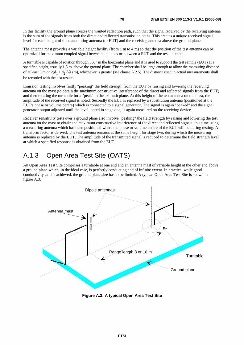
ETSI
Draft ETSI EN 300 113-1 V1.6.1 (2006-08) 78
In this facility the ground plane creates the wanted reflection path, such that the signal received by the receiving antenna is the sum of the signals from both the direct and reflected transmission paths. This creates a unique received signal level for each height of the transmitting antenna (or EUT) and the receiving antenna above the ground plane.
The antenna mast provides a variable height facility (from 1 m to 4 m) so that the position of the test antenna can be optimized for maximum coupled signal between antennas or between a EUT and the test antenna.
A turntable is capable of rotation through 360° in the horizontal plane and it is used to support the test sample (EUT) at a specified height, usually 1,5 m. above the ground plane. The chamber shall be large enough to allow the measuring distance of at least 3 m or 2(d1 + d2)2/λ (m), whichever is greater (see clause A.2.5). The distance used in actual measurements shall
be recorded with the test results.
Emission testing involves firstly "peaking" the field strength from the EUT by raising and lowering the receiving antenna on the mast (to obtain the maximum constructive interference of the direct and reflected signals from the EUT) and then rotating the turntable for a "peak" in the azimuth plane. At this height of the test antenna on the mast, the amplitude of the received signal is noted. Secondly the EUT is replaced by a substitution antenna (positioned at the EUT's phase or volume centre) which is connected to a signal generator. The signal is again "peaked" and the signal generator output adjusted until the level, noted in stage one, is again measured on the receiving device.
Receiver sensitivity tests over a ground plane also involve "peaking" the field strength by raising and lowering the test antenna on the mast to obtain the maximum constructive interference of the direct and reflected signals, this time using a measuring antenna which has been positioned where the phase or volume centre of the EUT will be during testing. A transform factor is derived. The test antenna remains at the same height for stage two, during which the measuring antenna is replaced by the EUT. The amplitude of the transmitted signal is reduced to determine the field strength level at which a specified response is obtained from the EUT.
A.1.3 Open Area Test Site (OATS) An Open Area Test Site comprises a turntable at one end and an antenna mast of variable height at the other end above a ground plane which, in the ideal case, is perfectly conducting and of infinite extent. In practice, while good conductivity can be achieved, the ground plane size has to be limited. A typical Open Area Test Site is shown in figure A.3.
Range length 3 or 10 mTurntable
Ground plane
Dipole antennas
Antenna mast
Figure A.3: A typical Open Area Test Site

ETSI
Draft ETSI EN 300 113-1 V1.6.1 (2006-08) 79
The ground plane creates a wanted reflection path, such that the signal received by the receiving antenna is the sum of the signals received from the direct and reflected transmission paths. The phasing of these two signals creates a unique received level for each height of the transmitting antenna (or EUT) and the receiving antenna above the ground plane.
Site qualification concerning antenna positions, turntable, measurement distance and other arrangements are same as for anechoic chamber with a ground plane. In radiated measurements an OATS is also used by the same way as anechoic chamber with a ground plane.
Typical measuring arrangement common for ground plane test sites is presented in the figure A.4.
T e s t a n t e n n a
T u r n t a b l e
P o w e r s u p p l y u n i t
D i g i t a l v o l t m e t e r
R e c e i v i n g d e v i c e
E U T
1 0 d B a t t e n u a t o r
Figure A.4: Measuring arrangement on ground plane test site (OATS set-up for spurious emission testing)
A.1.4 Test antenna A test antenna is always used in radiated test methods. In emission tests (i.e. frequency error, effective radiated power, spurious emissions and adjacent channel power) the test antenna is used to detect the field from the EUT in one stage of the measurement and from the substitution antenna in the other stage. When the test site is used for the measurement of receiver characteristics (i.e. sensitivity and various immunity parameters) the antenna is used as the transmitting device.
The test antenna should be mounted on a support capable of allowing the antenna to be used in either horizontal or vertical polarization which, on ground plane sites (i.e. Anechoic Chambers with ground planes and Open Area Test Sites), should additionally allow the height of its centre above the ground to be varied over the specified range (usually 1 metre to 4 metres).
In the frequency band 30 MHz to 1 000 MHz, dipole antennas (constructed in accordance with ANSI C63.5 [6]) are generally recommended. For frequencies of 80 MHz and above, the dipoles should have their arm lengths set for resonance at the frequency of test. Below 80 MHz, shortened arm lengths are recommended. For spurious emission testing, however, a combination of biconical antennas (commonly termed "bicones" and log periodic dipole array antennas (commonly termed "log periodics") could be used to cover the entire 30 MHz to 1 000 MHz band. Above 1 000 MHz, waveguide horns are recommended although, again, log periodics could be used.
NOTE: The gain of a horn antenna is generally expressed relative to an isotropic radiator.

ETSI
Draft ETSI EN 300 113-1 V1.6.1 (2006-08) 80
A.1.5 Substitution antenna The substitution antenna is used to replace the EUT for tests in which a transmitting parameter (i.e. frequency error, effective radiated power, spurious emissions and adjacent channel power) is being measured. For measurements in the frequency band 30 MHz to 1 000 MHz, the substitution antenna should be a dipole antenna (constructed in accordance with ANSI C63.5 [6]). For frequencies of 80 MHz and above, the dipoles should have their arm lengths set for resonance at the frequency of test. Below 80 MHz, shortened arm lengths are recommended. For measurements above 1 000 MHz, a waveguide horn is recommended. The centre of this antenna should coincide with either the phase centre or volume centre.
A.1.6 Measuring antenna The measuring antenna is used in tests on a EUT in which a receiving parameter (i.e. sensitivity and various immunity tests) is being measured. Its purpose is to enable a measurement of the electric field strength in the vicinity of the EUT. For measurements in the frequency band 30 MHz to 1 000 MHz, the measuring antenna should be a dipole antenna (constructed in accordance with ANSI C63.5 [6]. For frequencies of 80 MHz and above, the dipoles should have their arm lengths set for resonance at the frequency of test. Below 80 MHz, shortened arm lengths are recommended. The centre of this antenna should coincide with either the phase centre or volume centre (as specified in the test method) of the EUT.
A.2 Guidance on the use of radiation test sites This clause details procedures, test equipment arrangements and verification that should be carried out before any of the radiated test are undertaken. These schemes are common to all types of test sites described in annex A.
A.2.1 Verification of the test site No test should be carried out on a test site which does not possess a valid certificate of verification. The verification procedures for the different types of test sites described in annex A (i.e. Anechoic Chamber, Anechoic Chamber with a ground plane and Open Area Test Site) are given in TR 102 273 [4] Parts 2, 3 and 4, respectively.
A.2.2 Preparation of the EUT The manufacturer should supply information about the EUT covering the operating frequency, polarization, supply voltage(s) and the reference face. Additional information, specific to the type of EUT should include, where relevant, carrier power, channel separation, whether different operating modes are available (e.g. high and low power modes) and if operation is continuous or is subject to a maximum test duty cycle (e.g. 1 minute on, 4 minutes off).
Where necessary, a mounting bracket of minimal size should be available for mounting the EUT on the turntable. This bracket should be made from low conductivity, low relative dielectric constant (i.e. less than 1,5) material(s) such as expanded polystyrene, balsawood, etc.
A.2.3 Power supplies to the EUT All tests should be performed using power supplies wherever possible, including tests on EUT designed for battery-only use. In all cases, power leads should be connected to the EUT's supply terminals (and monitored with a digital voltmeter) but the battery should remain present, electrically isolated from the rest of the equipment, possibly by putting tape over its contacts.
The presence of these power cables can, however, affect the measured performance of the EUT. For this reason, they should be made to be "transparent" as far as the testing is concerned. This can be achieved by routing them away from the EUT and down to the either the screen, ground plane or facility wall (as appropriate) by the shortest possible paths. Precautions should be taken to minimize pick-up on these leads (e.g. the leads could be twisted together, loaded with ferrite beads at 0,15 m spacing or otherwise loaded).

ETSI
Draft ETSI EN 300 113-1 V1.6.1 (2006-08) 81
A.2.4 Volume control setting for analogue speech tests Unless otherwise stated, in all receiver measurements for analogue speech the receiver volume control where possible, should be adjusted to give at least 50 % of the rated audio output power. In the case of stepped volume controls, the volume control should be set to the first step that provides an output power of at least 50 % of the rated audio output power. This control should not be readjusted between normal and extreme test conditions in tests.
A.2.5 Range length The range length for all these types of test facility should be adequate to allow for testing in the far-field of the EUT i.e. it should be equal to or exceed:
( )2 1 2
2d d+
λ
where:
• d1 is the largest dimension of the EUT/dipole after substitution (m);
• d2 is the largest dimension of the test antenna (m);
• λ is the test frequency wavelength (m).
It should be noted that in the substitution part of this measurement, where both test and substitution antennas are half wavelength dipoles, this minimum range length for far-field testing would be:
2λ
It should be noted in test reports when either of these conditions is not met so that the additional measurement uncertainty can be incorporated into the results.
NOTE 1: For the fully anechoic chamber, no part of the volume of the EUT should, at any angle of rotation of the turntable, fall outside the "quiet zone" of the chamber at the nominal frequency of the test.
NOTE 2: The "quiet zone" is a volume within the Anechoic Chamber (without a ground plane) in which a specified performance has either been proven by test, or is guaranteed by the designer/manufacturer. The specified performance is usually the reflectivity of the absorbing panels or a directly related parameter (e.g. signal uniformity in amplitude and phase). It should be noted however that the defining levels of the quiet zone tend to vary.
NOTE 3: For the anechoic chamber with a ground plane, a full height scanning capability, i.e. 1 m to 4 m, should be available for which no part of the test antenna should come within 1 m of the absorbing panels. For both types of Anechoic Chamber, the reflectivity of the absorbing panels should not be worse than -5 dB.
NOTE 4: For both the anechoic chamber with a ground plane and the Open Area Test Site, no part of any antenna should come within 0,25 m of the ground plane at any time throughout the tests. Where any of these conditions cannot be met, measurements should not be carried out.

ETSI
Draft ETSI EN 300 113-1 V1.6.1 (2006-08) 82
A.2.6 Site preparation The cables for both ends of the test site should be routed horizontally away from the testing area for a minimum of 2 m (unless, in the case both types of anechoic chamber, a back wall is reached) and then allowed to drop vertically and out through either the ground plane or screen (as appropriate) to the test equipment. Precautions should be taken to minimize pick up on these leads (e.g. dressing with ferrite beads, or other loading). The cables, their routing and dressing should be identical to the verification set-up.
NOTE: For ground reflection test sites (i.e. anechoic chambers with ground planes and Open Area Test Sites) which incorporate a cable drum with the antenna mast, the 2 m requirement may be impossible to comply with.
Calibration data for all items of test equipment should be available and valid. For test, substitution and measuring antennas, the data should include gain relative to an isotropic radiator (or antenna factor) for the frequency of test. Also, the VSWR of the substitution and measuring antennas should be known.
The calibration data on all cables and attenuators should include insertion loss and VSWR throughout the entire frequency range of the tests. All VSWR and insertion loss figures should be recorded in the log book results sheet for the specific test.
Where correction factors/tables are required, these should be immediately available.
For all items of test equipment, the maximum errors they exhibit should be known along with the distribution of the error e.g.:
• cable loss: ±0,5 dB with a rectangular distribution;
• measuring receiver: 1,0 dB (standard deviation) signal level accuracy with a Gaussian error distribution.
At the start of measurements, system checks should be made on the items of test equipment used on the test site.
A.3 Coupling of signals
A.3.1 General The presence of leads in the radiated field may cause a disturbance of that field and lead to additional measurement uncertainty. These disturbances can be minimized by using suitable coupling methods, offering signal isolation and minimum field disturbance (e.g. optical and acoustic coupling).
A.3.2 Data Signals Isolation can be provided by the use of optical, ultrasonic or infra-red means. Field disturbance can be minimized by using a suitable fibre optic connection. ultrasonic or infra-red radiated connections require suitable measures for the minimization of ambient noise.
A.3.3 Speech and analogue signals Where an audio output socket is not available an acoustic coupler should be used.
When using the acoustic coupler, care should be exercised that possible ambient noise does not influence the test result.

ETSI
Draft ETSI EN 300 113-1 V1.6.1 (2006-08) 83
A.3.3.1 Acoustic coupler description
The acoustic coupler comprises a plastic funnel, an acoustic pipe and a microphone with a suitable amplifier. The materials used to fabricate the funnel and pipe should be of low conductivity and of low relative dielectric constant (i.e. less than 1,5).
• The acoustic pipe should be long enough to reach from the EUT to the microphone which should be located in a position that will not disturb the RF field. The acoustic pipe should have an inner diameter of about 6 mm and a wall thickness of about 1,5 mm and should be sufficiently flexible so as not to hinder the rotation of the turntable.
• The plastic funnel should have a diameter appropriate to the size of the loudspeaker in the EUT, with soft foam rubber glued to its edge, it should be fitted to one end of the acoustic pipe and the microphone should be fitted to the other end. It is very important to fix the centre of the funnel in a reproducible position relative to the EUT, since the position of the centre has a strong influence on the frequency response that will be measured. This can be achieved by placing the EUT in a close fitting acoustic mounting jig, supplied by the manufacturer, of which the funnel is an integral part.
• The microphone should have a response characteristic flat within 1 dB over a frequency range of 50 Hz to 20 kHz, a linear dynamic range of at least 50 dB. The sensitivity of the microphone and the receiver audio output level should be suitable to measure a signal to noise ratio of at least 40 dB at the nominal audio output level of the EUT. Its size should be sufficiently small to couple to the acoustic pipe.
• The frequency correcting network should correct the frequency response of the acoustic coupler so that the acoustic SINAD measurement is valid (see IEC 60489-3 [7], appendix F).
A.3.3.2 Calibration
The aim of the calibration of the acoustic coupler is to determine the acoustic SINAD ratio which is equivalent to the SINAD ratio at the receiver output.

ETSI
Draft ETSI EN 300 113-1 V1.6.1 (2006-08) 84
Annex B (normative): Specification for some particular measurement arrangements
B.1 Power measuring receiver specification The power measuring receiver consists of a mixer, an IF filter, an oscillator, an amplifier, a variable attenuator and a root mean squared (rms) value indicator.
Instead of the Variable attenuator with the rms value indicator it is also possible to use a rms voltmeter calibrated in dB. The technical characteristics of the power measuring receiver are given below.
An alternative measuring method shall consist in using, in place of the IF filter and the rms Voltmeter calibrated in dB, a spectrum analyser with a resolution bandwidth of 100 Hz and integrating the power of all the 100 Hz sub-band measurements, over a total bandwidth of ±D2 (see table B.1).
B.1.1 IF filter The IF filter shall be within the limits of the selectivity characteristic of figure B.1.
Figure B.1: IF filter
Depending on the channel separation, the selectivity characteristic shall keep the frequency separations from the nominal centre frequency of the adjacent channel as stated in table B.1.

ETSI
Draft ETSI EN 300 113-1 V1.6.1 (2006-08) 85
Table B.1: Selectivity characteristic
Channel separation (kHz)
Frequency separation of filter curve from nominal centre frequency of adjacent channel (kHz)
D1 D2 D3 D4 12,5 3 4,25 5,5 9,5 20 4 7,0 8,25 12,25 25 5 8,0 9,25 13,25
Depending on the channel separation, the attenuation points shall not exceed the tolerances as stated in tables B.2 and B.3.
Table B.2: Attenuation points close to carrier
Channel separation (kHz)
Tolerances range (kHz)
D1 D2 D3 D4 12,5 +1,35 ±0,1 -1,35 -5,35 20 +3,1 ±0,1 -1,35 -5,35 25 +3,1 ±0,1 -1,35 -5,35
Table B.3: Attenuation points distant from the carrier
Channel separation (kHz)
Tolerance range (kHz)
D1 D2 D3 D4 12,5 ±2,0 ±2,0 ±2,0 +2,0
-6,0 20 ±3,0 ±3,0 ±3,0 +3,0
-7,0 25 ±3,5 ±3,5 ±3,5 +3,5
-7,5
The minimum attenuation of the filter, outside the 90 dB attenuation points, shall greater than or equal to 90 dB.
B.1.2 Attenuation indicator The attenuation indicator shall have a minimum range of 80 dB and a reading accuracy of 1 dB. With a view to future regulations, an attenuation of 90 dB or more is recommended.
B.1.3 RMS value indicator The instrument shall accurately indicate non-sinusoidal signals in a ratio of up to 10:1 between peak value and rms value.
B.1.4 Oscillator and amplifier The oscillator and the amplifier shall be designed in such a way that the measurement of the adjacent channel power of a low-noise unmodulated transmitter, whose self-noise has a negligible influence on the measurement result, yields a measured value of ≤ -90 dB for channel separations of 20 kHz and 25 kHz and of ≤ -80 dB for a channel separation of 12,5 kHz, referred to the carrier of the oscillator.

ETSI
Draft ETSI EN 300 113-1 V1.6.1 (2006-08) 86
B.2 Spectrum analyser specification The specification shall include the following requirements.
It shall be possible, using a resolution bandwidth of 1 kHz, to measure the amplitude of a signal, or noise at a level 3 dB or more above the noise level of the spectrum analyser, as displayed on the screen, to an accuracy of ±2 dB in the presence of the wanted signal.
The accuracy of relative amplitude measurements shall be within ±1 dB.
For statistically distributed modulations, the spectrum analyser and the integrating device (when appropriate) shall allow determination of the real spectral power density (energy per time and bandwidth), which has to be integrated over the bandwidth in question.
NOTE: This point should be considered very carefully.
B.3 Integrating and power summing device The integrating and power summing device is connected to the video output of the spectrum analyser, referred to in clause B.2.
It shall be possible to sum the effective power of all discrete components, the spectral power density and the noise power in the selected bandwidth and to measure this as a ratio relative to the carrier power.
The position and the width of the integration range selected can be indicated on the spectrum analyser by brightening the trace.

ETSI
Draft ETSI EN 300 113-1 V1.6.1 (2006-08) 87
History
Document history
Edition 1 January 1992 Publication as I-ETS 300 113
Edition 2 June 1996 Publication as ETS 300 113
Amendment 1 March 1997 Amendment 1 to 2nd edition of ETS 300 113
V1.3.1 March 2001 Publication
V1.4.1 February 2002 Publication
V1.5.1 September 2003 Publication
V1.6.1 August 2006 Public Enquiry PE 20061208: 2006-08-09 to 2006-12-08