Curriculum Source References The following references were used ...

DRAFT DESIGN GUIDE
Fire SafetyResidential Community Housing
Consultation
JULY 2017

1. INTRODUCTION
Ministry of Business, Innovation & Employment (MBIE) Hīkina Whakatutuki Lifting to make successful
MBIE develops and delivers policy, services, advice and regulation to support economic growth and the prosperity and wellbeing of New Zealanders.
MBIE combines the former Ministries of Economic Development, Science and Innovation, and the Departments of Labour and Building and Housing.
Draft for consultation 17 July 2017 – 11 September 2017
Ministry of Business, Innovation & Employment PO Box 10-729, Wellington, New Zealand.
© Crown Copyright 2017
The material contained in this report is subject to Crown copyright protection unless otherwise indicated. The Crown copyright protected material may be reproduced free of charge in any format or media without requiring specific permission. This is subject to the material being reproduced accurately and not being used in a derogatory manner or in a misleading context. Where the material is being published or issued to others, the source and copyright status should be acknowledged. The permission to reproduce Crown copyright protected material does not extend to any material in this report that is identified as being the copyright of a third party. Authorisation to reproduce such material should be obtained from the copyright holders.
DATE: JULY 2017 DRAFT FOR CONSULTATION
INTRODUCTION
PAGE i i
INTRODUCTION
DESIGN GUIDE
DRAFT DESIGN GUIDE
1. INTRODUCTION
DATE: JULY 2017 DRAFT FOR CONSULTATION
INTRODUCTION
PAGE i i i
INTRODUCTION
Fire SafetyResidential Community Housing
DESIGN GUIDE
DRAFT DESIGN GUIDE
Guidance issued under Section 175 of the Building Act 2004
This design guide for residential community housing has been jointly developed by the Ministry of Business, Innovation & Employment (MBIE), Ministry of Health, New Zealand Fire Service, Housing New Zealand, Community Housing Aotearoa, New Zealand Disability Support Network, Disabled Person Assembly and a building control officer representative. It is published by the Chief Executive of MBIE as guidance under section 175 of the Building Act 2004 to help parties to comply with their obligations under this Act.
It is not mandatory to follow this design guide but, if followed, note that:
• it does not relieve any person of the obligation to consider any matter to which that information relates according to the circumstances of the particular case, and
• a building consent authority may have regard to this guidance but is not bound to accept a building design following this guidance as demonstrating compliance with the Building Code.
The intended users of this design guide are housing providers who provide housing to service providers funded by the Ministry of Health, who are subject to service management audit requirements. This guide will also be suitable for other organisations with similar audited management procedures in place.
All users of this design guide should satisfy themselves of the applicability of its content and should not act on the basis of any matter contained in the document without first considering and, if necessary, taking appropriate professional advice.
Applications for building consent and statutory declarations
An application for building consent using this design guide requires the confirmation of the intended household characteristics of the building (as per Table 2.1). The household characteristics and subsequent designs have been developed on the basis that there will be suitable, audited management practices to assist with the evacuation.
The building consent authority will require information to be satisfied that the building design will be suitable for its intended use.
This design guide recommends the building consent applicant to complete and supply the statutory declarations provided in Appendix D Forms D1 and D2. Even if a building consent application for residential community housing does not follow this design guide, MBIE considers it best practice to include these declarations, which confirm that the management processes for the building are, and shall remain, adequate for the building’s intended use. It is anticipated that funder contracts may require these statutory declarations as a condition of funding.
1. INTRODUCTION
DATE: JULY 2017 CONSULTATION
CONTENTS
PAGE 1
CONTENTS
ContentsReferences 3
Definitions 6
Part 1: General 17
1.1 Introduction and scope ........................................................................... 17
1.2 Using this design guide ...........................................................................18
1.3 Alterations to existing buildings ............................................................19
Part 2: Firecells, fire safety systems and fire resistance ratings 21
2.1 Provision of firecells ...............................................................................21
2.2 Fire safety systems ................................................................................21
2.3 Fire resistance ratings ........................................................................... 22
2.4 Visibility in escape routes ...................................................................... 24
2.5 Exit signs ............................................................................................... 25
Part 3: Means of escape 26
3.1 Escape routes ......................................................................................... 26
3.2 Doors on escape routes..........................................................................30
3.3 Door signs ..............................................................................................31
Part 4: Control of internal fire and smoke spread 34
4.1 Fire separations for housing types ........................................................ 34
4.2 Fire stopping ......................................................................................... 35
4.3 Firecell construction .............................................................................. 36
4.4 Surface finishes ..................................................................................... 39
Part 5: Control of external fire spread 42
5.1 Fire resistance ratings (FRR) ..................................................................... 42
5.2 Firecells on the same property................................................................. 42

1. INTRODUCTION
DATE: JULY 2017 CONSULTATION
CONTENTS
PAGE 2
CONTENTS
Fire SafetyResidential Community Housing
5.3 Roof projections ...................................................................................... 43
5.4 Protection from a lower roof in multi-unit dwellings ............................... 43
5.5 Exterior surface finishes .......................................................................... 44
5.6 Carports and similar construction............................................................ 44
Part 6: Firefighting 48
6.1 Fire Service vehicular access ....................................................................48
Part 7: Prevention of fire occurring 49
7.1 Solid fuel appliances ................................................................................. 49
7.2 Gas-burning appliances ............................................................................50
7.3 Oil-fired appliances ..................................................................................50
7.4 Recessed luminaires ..................................................................................51
7.5 Open fires ................................................................................................. 52
Appendix A (normative): Fire safety systems 59
A1.1 Fire alarm and sprinkler systems .............................................................60
A1.2 Requirements common to alarm systems ..............................................60
Appendix B (normative): Fire sprinkler systems 61
B1.1 Introduction .............................................................................................61
B2.1 Automatic fire sprinkler systems .............................................................61
B3.1 Residential fire sprinkler systems .......................................................... 62
B4.1 Sprinkler systems for houses ................................................................. 62
Appendix C (normative): Test methods 63
C1.1 General .................................................................................................... 63
C2.1 Flammability of floor coverings ............................................................. 63
C3.1 Flammability of suspended flexible fabrics and membrane structures .. 63
C4.1 Fire resistance ....................................................................................... 63
C5.1 Fire doors and smoke control doors .......................................................64
C6.1 Fire properties of external wall cladding systems ................................. 65
Appendix D: Statutory forms 67
DRAFT DESIGN GUIDE
DATE: JULY 2017 CONSULTATION
REFERENCES
PAGE 3
REFERENCES
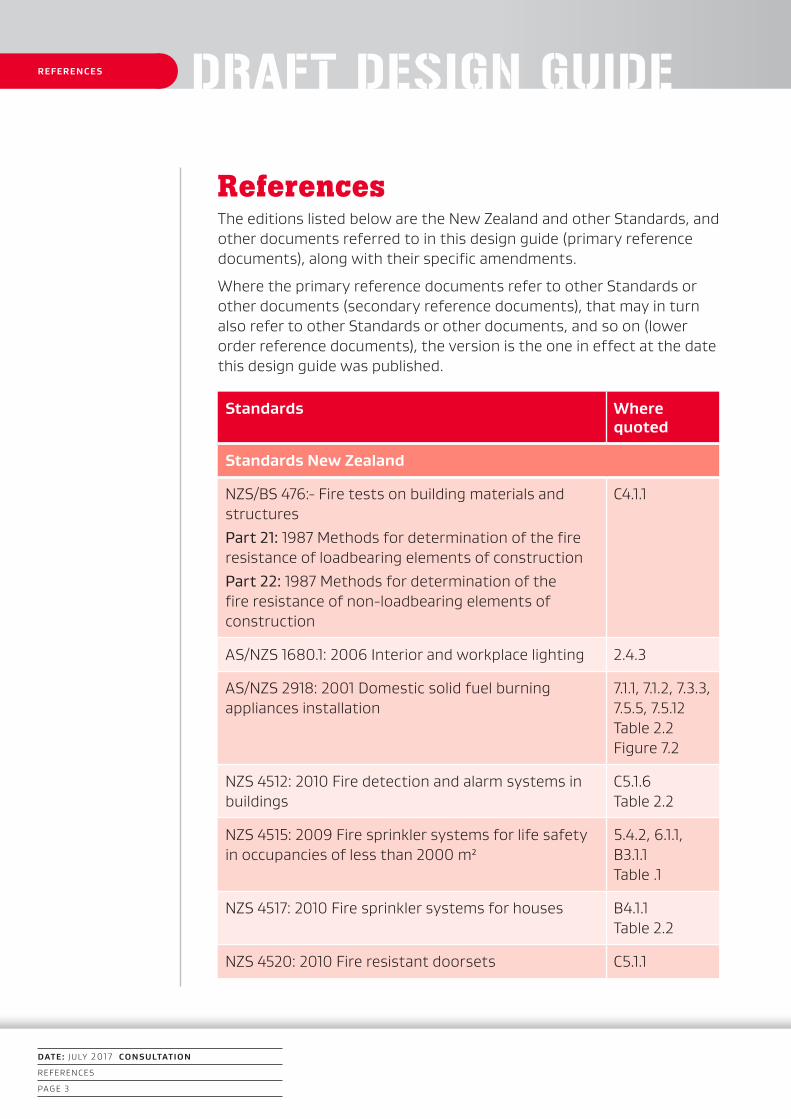
ReferencesThe editions listed below are the New Zealand and other Standards, and other documents referred to in this design guide (primary reference documents), along with their specific amendments.
Where the primary reference documents refer to other Standards or other documents (secondary reference documents), that may in turn also refer to other Standards or other documents, and so on (lower order reference documents), the version is the one in effect at the date this design guide was published.
Standards Where quoted
Standards New Zealand
NZS/BS 476:- Fire tests on building materials and structuresPart 21: 1987 Methods for determination of the fire resistance of loadbearing elements of constructionPart 22: 1987 Methods for determination of the fire resistance of non-loadbearing elements of construction
C4.1.1
AS/NZS 1680.1: 2006 Interior and workplace lighting 2.4.3
AS/NZS 2918: 2001 Domestic solid fuel burning appliances installation
7.1.1, 7.1.2, 7.3.3, 7.5.5, 7.5.12 Table 2.2 Figure 7.2
NZS 4512: 2010 Fire detection and alarm systems in buildings
C5.1.6 Table 2.2
NZS 4515: 2009 Fire sprinkler systems for life safety in occupancies of less than 2000 m²
5.4.2, 6.1.1, B3.1.1 Table .1
NZS 4517: 2010 Fire sprinkler systems for houses B4.1.1 Table 2.2
NZS 4520: 2010 Fire resistant doorsets C5.1.1
1. INTRODUCTION
DATE: JULY 2017 CONSULTATION
REFERENCES
PAGE 4
REFERENCES
Fire SafetyResidential Community Housing
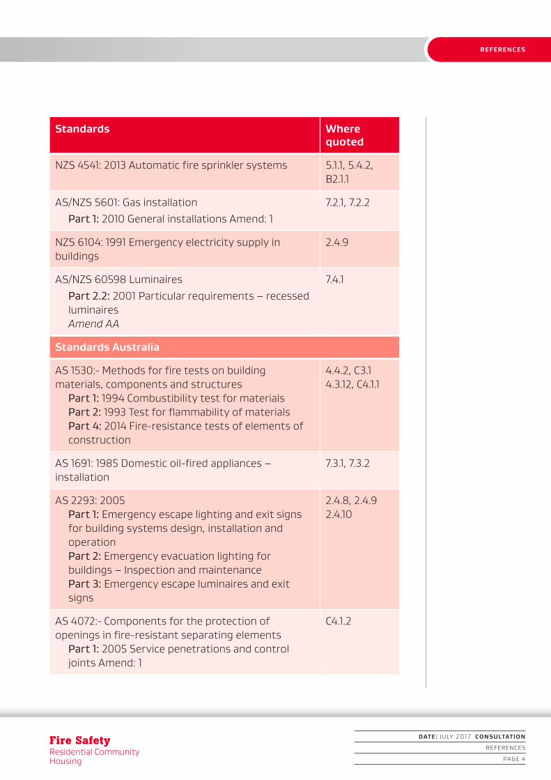
Standards Where quoted
NZS 4541: 2013 Automatic fire sprinkler systems 5.1.1, 5.4.2, B2.1.1
AS/NZS 5601: Gas installationPart 1: 2010 General installations Amend: 1
7.2.1, 7.2.2
NZS 6104: 1991 Emergency electricity supply in buildings
2.4.9
AS/NZS 60598 LuminairesPart 2.2: 2001 Particular requirements – recessed luminaires Amend AA
7.4.1
Standards Australia
AS 1530:- Methods for fire tests on building materials, components and structures
Part 1: 1994 Combustibility test for materials Part 2: 1993 Test for flammability of materials Part 4: 2014 Fire-resistance tests of elements of construction
4.4.2, C3.1 4.3.12, C4.1.1
AS 1691: 1985 Domestic oil-fired appliances – installation
7.3.1, 7.3.2
AS 2293: 2005 Part 1: Emergency escape lighting and exit signs for building systems design, installation and operation Part 2: Emergency evacuation lighting for buildings – Inspection and maintenance Part 3: Emergency escape luminaires and exit signs
2.4.8, 2.4.9 2.4.10
AS 4072:- Components for the protection of openings in fire-resistant separating elements
Part 1: 2005 Service penetrations and control joints Amend: 1
C4.1.2

1. INTRODUCTION
Standards Where quoted
International Organization for Standardization
ISO 5660:- Reaction-to-fire tests – Heat release, smoke production and mass loss rate
Part 1: 2015 Heat release rate (cone calorimeter method) and smoke production rate (dynamic measurement)
C6.1.1, C6.1.2
ISO 9239 Reaction to fire tests for flooring Part 1: 2010 Determination of the burning behaviour using a radiant heat source
C2.1
American Society for Testing and Materials
ASTM D 2898: 2010 Standard practice for accelerated weathering of fire-retardant-treated wood for fire testing
C6.1.3
DATE: JULY 2017 CONSULTATION
REFERENCES
PAGE 5
REFERENCES
DESIGN GUIDE 1. INTRODUCTIONDRAFT DESIGN GUIDE
Fire SafetyResidential Community Housing
Fire SafetyResidential Community Housing
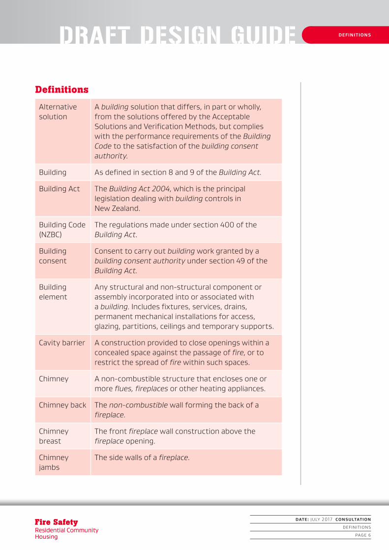
Definitions
Alternative solution
A building solution that differs, in part or wholly, from the solutions offered by the Acceptable Solutions and Verification Methods, but complies with the performance requirements of the Building Code to the satisfaction of the building consent authority.
Building As defined in section 8 and 9 of the Building Act.
Building Act The Building Act 2004, which is the principal legislation dealing with building controls in New Zealand.
Building Code (NZBC)
The regulations made under section 400 of the Building Act.
Building consent
Consent to carry out building work granted by a building consent authority under section 49 of the Building Act.
Building element
Any structural and non-structural component or assembly incorporated into or associated with a building. Includes fixtures, services, drains, permanent mechanical installations for access, glazing, partitions, ceilings and temporary supports.
Cavity barrier A construction provided to close openings within a concealed space against the passage of fire, or to restrict the spread of fire within such spaces.
Chimney A non-combustible structure that encloses one or more flues, fireplaces or other heating appliances.
Chimney back The non-combustible wall forming the back of a fireplace.
Chimney breast
The front fireplace wall construction above the fireplace opening.
Chimney jambs
The side walls of a fireplace.
DEFINITIONS
DATE: JULY 2017 CONSULTATION
DEFINITIONS
PAGE 6

1. INTRODUCTION1. INTRODUCTION1. INTRODUCTION
DATE: JULY 2017 CONSULTATION
DEFINITIONS
PAGE 7
DEFINITIONS
Combustible See non-combustible.
Communal service functions
Spaces that provide day-to-day service functions to support the sleeping areas, which have a higher fire risk than direct support functions. These are generally enclosed spaces and include, but are not limited to, offices, waiting rooms, lounges, storage rooms or cupboards, utility cupboards, linen cupboards (< 3 m³), dining rooms, laundries and kitchens.
Controlled egress
The restriction of residents’ movements by using locking devices to restrict free movement for escape.
Dead end That part of an open path where escape is possible in only one direction.
Direct support functions
Activities that provide support to the building’s main function and that are open areas of low fire risk and low fire load. These may include, but are not limited to, reception desks, nurses’ stations, kiosks, tea bays, sanitary facilities and mail boxes.
Doorset A complete assembly comprising: a door leaf or leaves including(a) any glazed or solid panels adjacent to or over the
leaves within the door frame including hardware or other inbuilt features; and
(b) a door frame, if any, with its fixings to the wall; and,
(c) for a sliding or tilting door, all guides and their respective fixings to the lintel, wall or sill.
Escape height The height between the floor level in the firecell being considered and the floor level of the required final exit which is the greatest vertical distance above or below that firecell.
Escape route A continuous unobstructed route from any occupied space in a building to a final exit to enable occupants to reach a safe place, and that shall consist of open paths and safe paths.

1. INTRODUCTION1. INTRODUCTION
Fire SafetyResidential Community Housing
DEFINITIONS
DATE: JULY 2017 CONSULTATION
DEFINITIONS
PAGE 8
Fire SafetyResidential Community Housing
Exitway All parts of an escape route protected by fire and smoke separations, or by distance when exposed to open air, and terminating at a final exit.
External wall Any exterior face of a building within 30° of vertical, consisting of primary and/or secondary elements intended to provide protection against the outdoor environment, but which may also contain unprotected areas.
Final exit The point at which an escape route terminates by giving direct access to a safe place.
Fire The state of combustion during which flammable materials burn producing heat, toxic gases, smoke or flame or any combination of these.
Firecell Any space, including a group of contiguous spaces on the same or different levels within a building, which is enclosed by any combination of fire separations, external walls, roofs and floors.
Fire door A doorset, single or multi-leaf, having a specific fire resistance rating, and in certain situations a smoke control capability, and forming part of a fire separation. The door, in the event of a fire, if not already closed, will close automatically and will be self-latching.
Fireplace A space formed by the chimney back, the chimney jambs, and the chimney breast in which fuel is burned for the purpose of heating the room into which it opens.
Fire resistance rating (FRR)
The term used to describe the minimum fire resistance required of primary and secondary elements as determined in the standard test for fire resistance, or in accordance with a specific calculation method verified by experimental data from standard fire resistance tests. It comprises three numbers giving the time in minutes for which each of the criteria structural adequacy, integrity and insulation are satisfied, and is presented always in that order.
1. INTRODUCTION
DATE: JULY 2017 CONSULTATION
DEFINITIONS
PAGE 9
DEFINITIONS
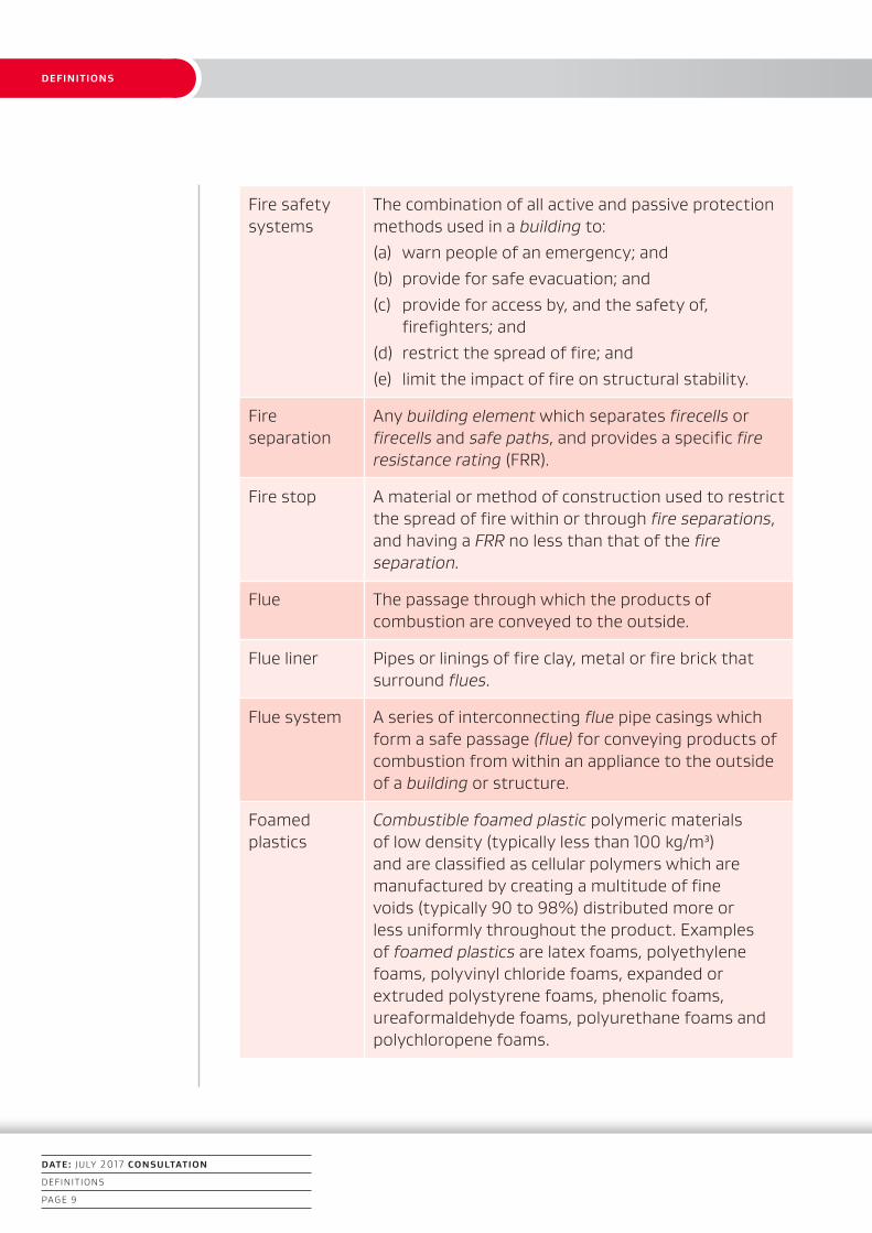
Fire safety systems
The combination of all active and passive protection methods used in a building to:(a) warn people of an emergency; and(b) provide for safe evacuation; and(c) provide for access by, and the safety of,
firefighters; and(d) restrict the spread of fire; and(e) limit the impact of fire on structural stability.
Fire separation
Any building element which separates firecells or firecells and safe paths, and provides a specific fire resistance rating (FRR).
Fire stop A material or method of construction used to restrict the spread of fire within or through fire separations, and having a FRR no less than that of the fire separation.
Flue The passage through which the products of combustion are conveyed to the outside.
Flue liner Pipes or linings of fire clay, metal or fire brick that surround flues.
Flue system A series of interconnecting flue pipe casings which form a safe passage (flue) for conveying products of combustion from within an appliance to the outside of a building or structure.
Foamed plastics
Combustible foamed plastic polymeric materials of low density (typically less than 100 kg/m³) and are classified as cellular polymers which are manufactured by creating a multitude of fine voids (typically 90 to 98%) distributed more or less uniformly throughout the product. Examples of foamed plastics are latex foams, polyethylene foams, polyvinyl chloride foams, expanded or extruded polystyrene foams, phenolic foams, ureaformaldehyde foams, polyurethane foams and polychloropene foams.

1. INTRODUCTION
Step 2
Building owner contacts council
for advice and consent
requirements if applicable
Fire SafetyResidential Community Housing
DEFINITIONS
DATE: JULY 2017 CONSULTATION
DEFINITIONS
PAGE 10
FRR See fire resistance rating.
Group Number
The classification number for a material used as a finish, surface, lining, or attachment to a wall or ceiling within an occupied space and determined according to the standard test methods for measuring the properties of lining materials.
Note: The method for determining a Group Number is described in Verification Method C/VM2 Appendix A.
Group sleeping
A firecell containing communal sleeping accommodation for a specified number of people within the limitations set by this design guide.
Hold-open devices
A device which holds a smoke control door or fire door open during normal use, but is released by deactivating the device by an automatic fire detection system, allowing the door to close automatically under the action of a self-closing device.
Household characteristics
The resident characteristics of those residents needing the most assistance to exit a building.
Household unit
This term:(a) means a building or group of buildings, or part of
a building or group of buildings, that is: i) used, or intended to be used, only or
mainly for residential purposes; andii) occupied, or intended to be occupied,
exclusively as the home or residence of notmore than one household; but
(b) does not include a hostel, boarding house, or other specialised accommodation.
Housing characteristics
A graded level of fire safety systems and building features commensurate with the abilities of the residents.
Independent means of escape
An escape route from a firecell that is separated from adjacent firecells by either distance or fire-rated construction.

1. INTRODUCTION
DATE: JULY 2017 CONSULTATION
DEFINITIONS
PAGE 11
DEFINITIONS
Independent service provider
A provider not funded by the Ministry of Health nor where the organisation providing support services has a similar services management audit procedure in place.
Insulating material
A material that has a thermal conductivity of less than 0.07 W/mK.
Insulation In the context of fire protection, the time in minutes for which a prototype specimen of a fire separation, when subjected to the standard test for fore resistance, has limited the transmission of heat through the specimen.
Integrity In the context of fire protection, the time in minutes for which a prototype specimen of a fire separation, when subjected to the standard test for fire resistance, has prevented the passage of flame or hot gases.
Intermediate floor
Any upper floor within a firecell which because of its configuration, provides an opening allowing smoke or fire to spread from a lower to an upper level within the firecell.
Life rating The fire resistance rating to be applied to elements of construction that allows movement of people from their location in a building to a safe place.
Means of escape
In relation to a building that has a floor area:(a) means continuous unobstructed routes of travel
from any part of the floor area of that building to a place of safety; and
(b) includes all active and passive protection features required to warn people of fire and to assist in protecting people from the effects of fire in the course of their escape from the fire.
Multi-unit dwelling
A building or use which contains more than one separate household or family.
Non-combustible
Materials shall be classified as combustible or non-combustible when tested to AS 1530 Part 1.
1. INTRODUCTION
Fire SafetyResidential Community Housing
DEFINITIONS
DATE: JULY 2017 CONSULTATION
DEFINITIONS
PAGE 12
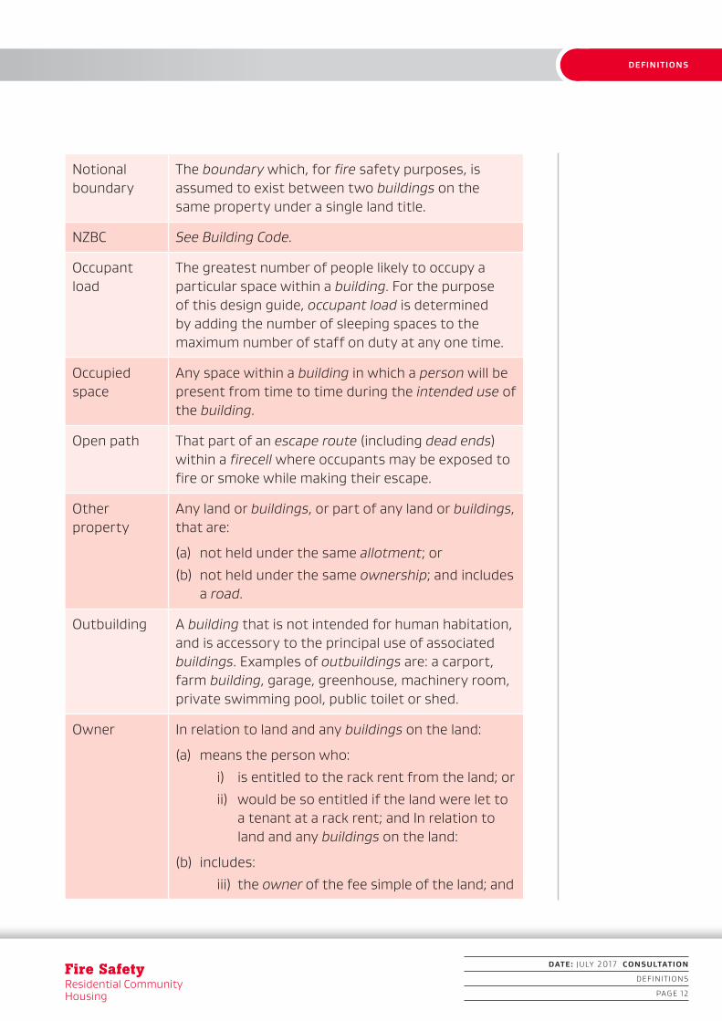
Notional boundary
The boundary which, for fire safety purposes, is assumed to exist between two buildings on the same property under a single land title.
NZBC See Building Code.
Occupant load
The greatest number of people likely to occupy a particular space within a building. For the purpose of this design guide, occupant load is determined by adding the number of sleeping spaces to the maximum number of staff on duty at any one time.
Occupied space
Any space within a building in which a person will be present from time to time during the intended use of the building.
Open path That part of an escape route (including dead ends) within a firecell where occupants may be exposed to fire or smoke while making their escape.
Other property
Any land or buildings, or part of any land or buildings, that are:
(a) not held under the same allotment; or
(b) not held under the same ownership; and includes a road.
Outbuilding A building that is not intended for human habitation, and is accessory to the principal use of associated buildings. Examples of outbuildings are: a carport, farm building, garage, greenhouse, machinery room, private swimming pool, public toilet or shed.
Owner In relation to land and any buildings on the land:
(a) means the person who:
i) is entitled to the rack rent from the land; or
ii) would be so entitled if the land were let toa tenant at a rack rent; and In relation to land and any buildings on the land:
(b) includes:
iii) the owner of the fee simple of the land; and
1. INTRODUCTION
DATE: JULY 2017 CONSULTATION
DEFINITIONS
PAGE 13
DEFINITIONS
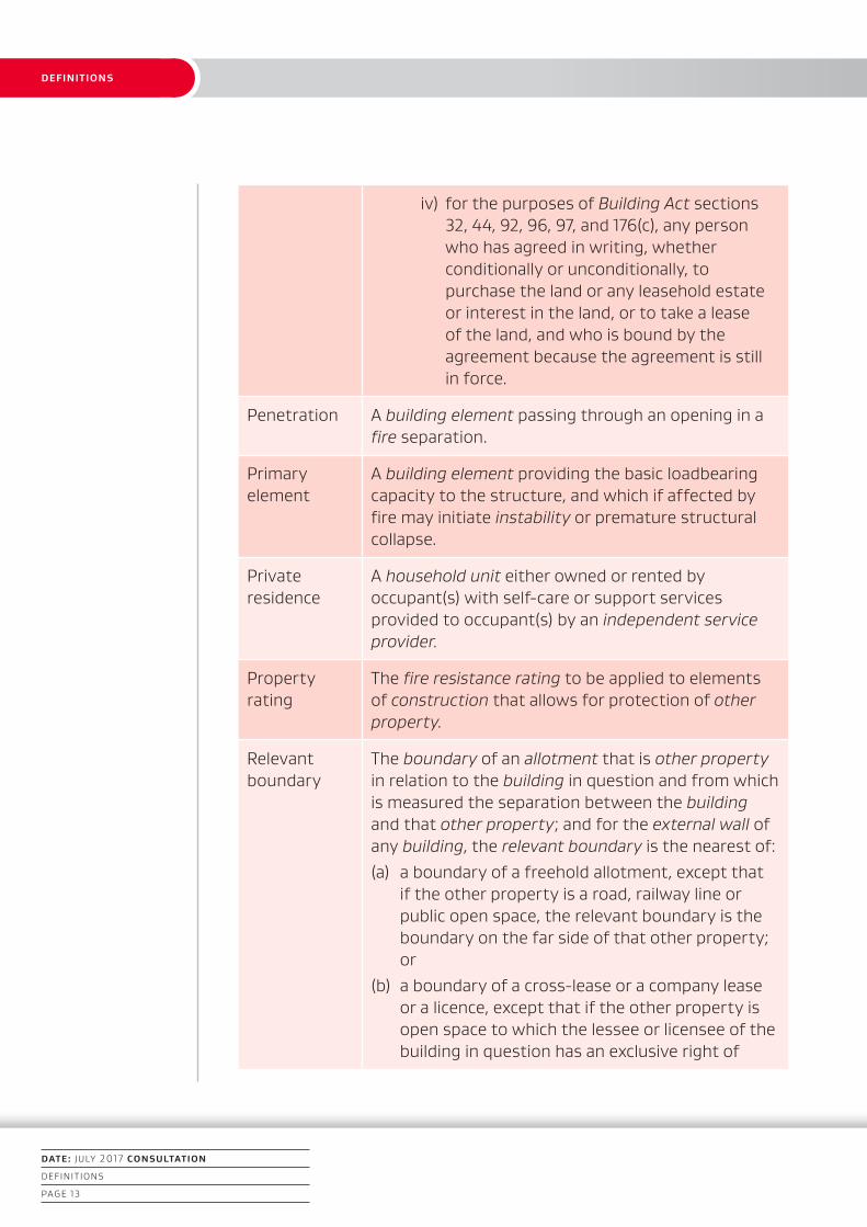
iv) for the purposes of Building Act sections32, 44, 92, 96, 97, and 176(c), any person who has agreed in writing, whether conditionally or unconditionally, to purchase the land or any leasehold estate or interest in the land, or to take a lease of the land, and who is bound by the agreement because the agreement is stillin force.
Penetration A building element passing through an opening in a fire separation.
Primary element
A building element providing the basic loadbearing capacity to the structure, and which if affected by fire may initiate instability or premature structural collapse.
Private residence
A household unit either owned or rented by occupant(s) with self-care or support services provided to occupant(s) by an independent service provider.
Property rating
The fire resistance rating to be applied to elements of construction that allows for protection of other property.
Relevant boundary
The boundary of an allotment that is other property in relation to the building in question and from which is measured the separation between the building and that other property; and for the external wall of any building, the relevant boundary is the nearest of:(a) a boundary of a freehold allotment, except that
if the other property is a road, railway line or public open space, the relevant boundary is the boundary on the far side of that other property; or
(b) a boundary of a cross-lease or a company lease or a licence, except that if the other property is open space to which the lessee or licensee of the building in question has an exclusive right of

1. INTRODUCTION
Fire SafetyResidential Community Housing
DEFINITIONS
DATE: JULY 2017 CONSULTATION
DEFINITIONS
PAGE 14
access and occupation or to which two or more occupiers of the building in question have rights of access and occupation, the relevant boundary is the boundary on the far side of that other property; or
(c) a boundary shown on a unit plan (but excluding a boundary between a principal unit and its accessory unit), except that if the other property is open space and is common property, the relevant boundary is the boundary on the far side of that other property.
Resident A person living in residential community housing.
Resident characteristics
The abilities and requirements of each resident as established by the service provider.
Residential community housing
A residential building or part of a building other than a private residence where support services are provided to the building’s residents by a service provider.
Service provider
A person or organisation that provides support services to a resident or residents within residential community housing.
Note: Service providers have audited management procedures in place.
Safe place A place outside, and in the vicinity of, a single building unit from which people may safely disperse after escaping the effects of a fire. It may be a place such as a street, open space, public space, or an adjacent building unit.
Secondary element
A building element not providing load bearing capacity to the structure and that if, affected by fire, instability or collapse of the building structure will not occur.
1. INTRODUCTION
DATE: JULY 2017 CONSULTATION
DEFINITIONS
PAGE 15
DEFINITIONS
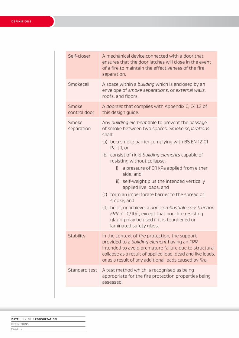
Self-closer A mechanical device connected with a door that ensures that the door latches will close in the event of a fire to maintain the effectiveness of the fire separation.
Smokecell A space within a building which is enclosed by an envelope of smoke separations, or external walls, roofs, and floors.
Smoke control door
A doorset that complies with Appendix C, C4.1.2 of this design guide.
Smoke separation
Any building element able to prevent the passage of smoke between two spaces. Smoke separations shall:(a) be a smoke barrier complying with BS EN 12101
Part 1, or(b) consist of rigid building elements capable of
resisting without collapse:i) a pressure of 0.1 kPa applied from either
side, andii) self-weight plus the intended vertically
applied live loads, and(c) form an imperforate barrier to the spread of
smoke, and(d) be of, or achieve, a non-combustible construction
FRR of 10/10/-, except that non-fire resisting glazing may be used if it is toughened or laminated safety glass.
Stability In the context of fire protection, the support provided to a building element having an FRR intended to avoid premature failure due to structural collapse as a result of applied load, dead and live loads, or as a result of any additional loads caused by fire.
Standard test A test method which is recognised as being appropriate for the fire protection properties being assessed.

1. INTRODUCTION
Fire SafetyResidential Community Housing
DEFINITIONS
DATE: JULY 2017 CONSULTATION
DEFINITIONS
PAGE 16
Structural adequacy
In the context of the standard test for fire resistance, the time in minutes for which a prototype specimen has continued to carry its applied load within defined deflection limits.
Support services
Support given to a resident to carry out their day-to-day activities that is provided by others, whether full-time or part-time and whether paid or unpaid.
Surface finish The combination of a surface coating and substrate material on surfaces of building elements exposed to view. It can be an applied decorative coating or the uncoated building element itself. For interior surfaces the requirements are evaluated in terms of a Group Number. For exterior surfaces the requirements are evaluated in terms of rate of heat release as determined by Appendix C Paragraph C6.1.
Travel distance
The length of the escape route as a whole or the individual length of its parts, namely: (a) open paths, and (b) safe paths.
Unprotected area
In relation to an external wall of a building, means:
(a) any part of the external wall which is not fire rated or has less than the required FRR, andany part of the external wall which has combustible material more than 1.0 mm thick attached or applied to its external face, whether for cladding or any other purpose.
DRAFT DESIGN GUIDE
DATE: JULY 2017 CONSULTATION
PART ONE
PAGE 17
PART ONE
Part 1: General
1.1 Introduction and scope
Introduction
This design guide is guidance to assist the preparation of an Alternative Solution for establishing compliance with NZBC Clauses C1–C6 (Protection from fire) and F6–F8 (Visibility in escape routes, warning systems, and signs) for residential community housing.
Words in italics are defined at the front of this document.
1.1.1 Scope
The scope of this design guide is restricted to residential community housing where support services are either funded by the Ministry of Health, or where the organisation providing support services has a similar service management audit procedure in place. This includes the following:
(a) single-storey or two-storey dwellings providing accommodation for no more than 10 residents; and where the dwelling is within the limitations of Table 2.1;
(b) multi-unit dwellings containing residential community housing that provide accommodation for no more than 10 residents per unit, with no more than one unit above another, where each unit has an escape route independent of all other units; and where the dwelling is within the limitations of Table 2.1; and
(c) all garages or carports that are associated with the residential community housing.
1.1.2 Outside the scope of this design guide
Buildings or parts of buildings that are:
(a) not within the scope of Paragraph 1.1.1; or
(b) private residences
(c) those where the service providers are not funded by the Ministry of Health or other recognised service provider; or
(d) multi-storey apartments or commercial buildings.

1. INTRODUCTION
DATE: JULY 2017 CONSULTATION
PART ONE
PAGE 18
PART ONE
Fire SafetyResidential Community Housing
1.1.3.
This design guide does not provide for the building features that would be required for a stay-in-place strategy.
1.2 Using this design guide
1.2.1
The process for using this design guide is as follows.
Step 1: Determine the applicability of this design guide
Establish whether the proposal falls within the scope of this design guide (see Paragraphs 1.1.1 to 1.1.3).
Step 2 Determine the resident characteristics
The service provider shall establish the abilities and requirements of each resident in order to determine the resident characteristics from Table 1.1.
Step 3: Evaluate the household
Establish the housing characteristics and then determine the building’s minimum housing type (see Part 2).
An application for building consent using this design guide requires the confirmation of the intended household characteristics (as per Table 2.1).
Example:
The housing characteristics are determined by those residents needing the most assistance to exit a building. The number of residents in this category may or may not equate to the total number of residents. For example, the house may accommodate ten residents, with nine who need a low level of support (resident characteristic LSR), and just one requiring a very high level of support (VHSR). The household characteristics are VHSR and the number of residents for consideration in Table 2.1 would therefore be one.

1. INTRODUCTION
DATE: JULY 2017 CONSULTATION
PART ONE
PAGE 19
PART ONE
Step 4: Determine the fire safety requirements specific for residential community housing
Determine the fire safety requirements of this design guide (see Parts 2–7), based on the housing type, occupant load, number of residents for consideration, the building’s dimensions and other building features.
Step 5: Establish other NZBC fire safety requirements
Using the relevant building information establish any other requirements for means of escape or protection of other property.
Step 6: Complete the occupancy declarations
This design guide recommends the statutory declaration Forms D1 and D2 in Appendix D are completed and included with an application for building consent.
Note:
Even if this design guide is not followed in its entirety, it is considered best practice to include these statutory declarations when applying for a building consent. These declarations confirm that the management processes for the building are, and shall remain, adequate for the building’s intended use.
Table 1.1 Resident characteristics
Low Support Resident (LSR)
• Understands verbal, electronic, or other fire warnings with little or no prompting; and
• Has the physical ability and means to exit the building with a low level of assistance (including when woken from sleep).
Medium Support Resident (MSR)
• Requires a moderate degree of assistance in understanding verbal, electronic, or other fire warnings: and/or
• Requires a moderate degree of assistance to exit the building within appropriate timeframes.

1. INTRODUCTION
DATE: JULY 2017 CONSULTATION
PART ONE
PAGE 20
PART ONE
Fire SafetyResidential Community Housing
High Support Resident
(HSR)
• Requires significant levels of assistance in understanding verbal, electronic, or other fire warnings; and/or
• Requires significant levels of assistance in physically exiting the building within appropriate timeframes.
Very High Support Resident (VHSR)
• Requires full assistance from their service provider to evacuate the building within appropriate timeframes.
1.3 Alterations to existing buildings
This design guide can be used to undertake a gap assessment for establishing compliance as near as is reasonably practicable (ANARP) in accordance with section 112 of the Building Act.
DRAFT DESIGN GUIDE
DATE: JULY 2017 CONSULTATION
PART TWO
PAGE 21
PART TWO
Part 2: Firecells, fire safety systems and fire resistance ratings
2.1 Provision of firecells
2.1.1 Firecell floor area limits
The floor area of a firecell within residential community housing shall not exceed 500 m².
2.2 Fire safety systems
2.2.1
The fire safety systems required for buildings within the scope of this design guide shall be determined as follows:
Step 1: Determine the residential community housing type
From Table 2.1 determine the minimum housing type required from the household characteristics (as identified in Part 1 of this design guide), and the maximum number of residents determined from the evaluated household (see Paragraph 1.2.1 Step 3). If controlled egress is also required see Paragraph 3.2.3.
Step 2: Determine the building features and fire safety systems
Using Table 2.2, determine the required building features and minimum fire safety systems.
Note:
Additional fire safety systems can be voluntarily included within the property.

1. INTRODUCTION
Fire SafetyResidential Community Housing
DATE: JULY 2017 CONSULTATION
PART TWO
PAGE 22
PART TWO
2.3 Fire resistance ratings
Fire resistance ratings values – life and property ratings
2.3.1
The fire resistance ratings (FRRs) for the life and property ratings are both 30 minutes [(30)/30/30].
An insulation rating is not required where sprinklers are provided.
2.3.2
Areas of the external wall that are not permitted to be unprotected areas shall be rated for fire exposure from both sides equally where:
(a) walls are within 1.0 m of the relevant boundary, or
(b) the final exit is one or more floor levels below any sleeping use.
Table 2.1 Housing type
Household characteristics
Number of residents*
Minimum housing type
LSR 1–6 A
LSR 7–10 B
MSR 1–3 B
MSR 4–10 C
HSR 1–2 C
HSR 3–10 D
VHSR 1 C
VHSR 2–10 D
Notes:
1. For definitions of LSR, MSR, HSR and VHSR see Table 1.1 and the example in Paragraph 1.2.
2. If controlled egress is required, see Paragraph 3.2.3 for the specified housing types and associated features.
* Determined from methodology described in Paragraph 1.2.1.

1. INTRODUCTION
DATE: JULY 2017 CONSULTATION
PART TWO
PAGE 23
PART TWO
Table 2.2Building features and minimum fire safety systemsHousing type
A
• Maximum of two storeys
• Single firecell
• Interconnected smoke and heat alarms to NZS 4514
B
• Maximum of two storeys
• A minimum of two firecells or a domestic sprinkler system to NZS 4517
• Interconnected smoke and heat alarms to NZS 4514
C
• Single storey with an escape height of less than 2.0 m
• A minimum of two firecells
• Interconnected smoke and heat alarms to NZS 4514
• Domestic sprinkler system to NZS 4517
• Visibility in escape routes to the requirements of NZBC Part F6
D
• Single storey with an escape height of less than 2.0 m
• A minimum of two firecells
• Smoke detectors to NZS 4512
• Domestic sprinkler system to NZS 4517
• Visibility in escape routes to the requirements of NZBC Part F6
1. INTRODUCTION
Fire SafetyResidential Community Housing
DATE: JULY 2017 CONSULTATION
PART TWO
PAGE 24
PART TWO
2.4 Visibility in escape routes
2.4.1 Location
Where visibility in escape routes is required (see Table 2.2) it shall be provided in the escape routes and at final exits from sleeping areas in accordance with NZBC Clause F6.
2.4.2
If required, the emergency lighting must provide a direct illuminance of no less than:
(a) 1.0 lux at every change in level in an escape route, and
(b) 0.2 lux everywhere else.
2.4.3 Method of measurement
Illuminance must be measured in accordance with Appendix B of AS/NZS 1680.1, with measurements made at floor level.
2.4.4
Measurements must not be made within 500 mm of vertical surfaces. Minimum illuminance will generally occur furthest from the luminaire(s), and at least four measurements shall be made around each luminaire on both axes. If the layout of luminaires is symmetrical, the number of measurements may be reduced in accordance with Appendix B of AS/NZS1680.1 Requirements.
2.4.5
Daylight or spill light from adjacent rooms must be excluded and the lamps switched on and allowed to stabilise before measurements are taken.
2.4.6 Start up and light output
The emergency lighting system must initiate within the following times and provide:
(a) 10% of the design illuminance level in 20 seconds, and
(b) 80% of the design illuminance level in 60 seconds in all other locations.
2.4.7 Duration
Emergency lighting must have a minimum duration of 30 minutes.
1. INTRODUCTION
DATE: JULY 2017 CONSULTATION
PART TWO
PAGE 25
PART TWO
2.4.8 Installation, maintenance and equipment
An emergency lighting system must be installed in accordance with:
(a) AS 2293: Parts 1 and 3 as amended by Appendix B (F6/AS1), and
(b) NZBC Clause G9, Electricity.
Emergency lighting installations must be commissioned after the successful completion of tests to confirm automatic operation upon tripping or failure of the power supply to the normal lighting circuits and must include testing of any phase failure devices. Such tests must be repeated on the completion of any addition to, or alteration of, the installed system.
2.4.9
Notwithstanding the requirements of Paragraph 2.4.8(a) a generator that is installed and maintained in accordance with NZS 6104, as amended by Appendix C F8/AS1, is an acceptable emergency power supply to meet Section 3 of AS 2293 Part 1, providing the emergency lighting has priority as the initial load.
2.4.10
Inspection, maintenance and reporting procedures for central battery and single point systems shall be performed in accordance with AS/NZS 2293 Part 2.
2.5 Exit signs
2.5.1
Illuminated exit signage is not a requirement of this design guide.
2.5.2
For housing types C and D a non-illuminated sign shall be provided above each final exit.

DRAFT DESIGN GUIDE
DATE: JULY 2017 CONSULTATION
PART THREE
PAGE 26
PART THREE
Fire SafetyResidential Community Housing
Part 3: Means of escape
3.1 Escape routes
3.1.1 Number of escape routes
Each firecell shall have independent means of escape provided that the dead end open path and total open path limitations are not exceeded. The minimum number of escape routes shall be as specified in Table 3.1.
3.1.2 Height and width of escape routes
Height requirements within escape routes shall be as follows:
(a) the clear height shall be no less than 2100 mm across the full width, except that isolated ceiling fittings not exceeding 200 mm in diameter may project downwards to reduce this clearance by no more than 100 mm, and
(b) any door opening within or giving access to any escape route shall have a clear height of no less than 1955 mm for the required width of the opening.
3.1.3
Corridor widths shall be in accordance with Table 3.2.
3.1.4 Length of escape routes
The lengths of dead ends and total open paths within residential community housing shall not exceed:
(a) 18 m dead end, and
(b) 36 m total open path.
(See Figure 3.2.)
3.1.5 Stairs on escape routes
To calculate stair length, take the plan length measured on the stairs’ centerline, multiply by 1.2, and add the length of each landing.
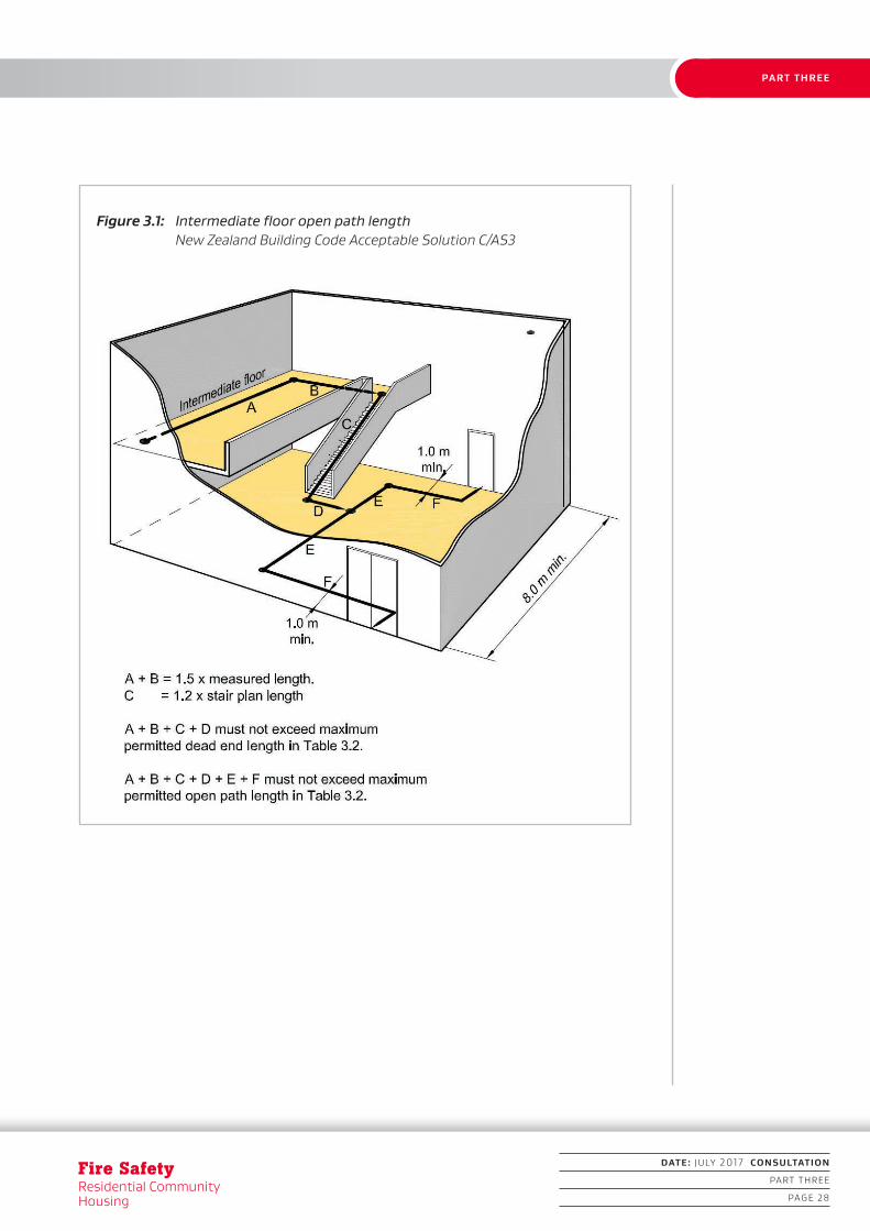
3.1.6 Open paths
Where two or more designated escape routes are required they shall be separated from each other and remain separated until reaching an exitway or final exit. Separation shall be achieved by diverging (from the point where two escape routes are required) at an angle of no less than

1. INTRODUCTION
DATE: JULY 2017 CONSULTATION
PART THREE
PAGE 27
PART THREE
90° until separated by:
(a) a distance of 8.0 m, or
(b) smoke separations and smoke control doors inclusive of self-closers.
(See Figures 3.1 and 3.2.)
3.1.7 Passing into an adjacent firecell
Where two or more firecells are required, the means of escape serving both firecells shall have:
(a) no fewer than two directions of escape (one being into the adjacent firecell), separated as required by Paragraph 3.1.6, and
(b) at least one escape route leading directly to a final exit or external safe path that is totally independent of the escape route into and from the adjacent firecell.
3.1.8 External safe paths
Where an escape route enters a space exposed to the open air (eg an open stairway, a balcony, across a roof or a ground level path) it shall not pass within 2.0 m of any unprotected areas where the firecell is unsprinklered and 1.0 m when sprinklered, on the way to a safe place.
3.1.9
Except where the separation distance requirements of Paragraph 3.1.8 are achieved:
(a) external walls and roofs adjacent to external escape routes shall comply with the FRR requirements of Part 5 of this design guide and have no unprotected areas, and
(b) if the escape route is a balcony with a single direction of escape, and the vertical distance between the underside of the balcony and the closest unprotected area in the external wall below is less than 5.0 m, balcony barriers shall:
i) have no openings, and
ii) be protected with a material that has a Group Number of 1.
1. INTRODUCTION
Fire SafetyResidential Community Housing
DATE: JULY 2017 CONSULTATION
PART THREE
PAGE 28
PART THREE
Figure 3.1: Intermediate floor open path length New Zealand Building Code Acceptable Solution C/AS3

1. INTRODUCTION
DATE: JULY 2017 CONSULTATION
PART THREE
PAGE 29
PART THREE
Figure 3.2: Alternative open path seperation New Zealand Building Code Acceptable Solution C/AS3
3.1.10 Single escape routes
Single escape routes are permissible only where the dead end open path is within the limitations of Paragraph 3.1.4 and the occupant load does not exceed 50 people.
3.1.11 Accessibility
Escape routes must comply with NZBC Clause D1. Ramps, stairs, ladders, landings, handrails, doors, vision panels and openings shall comply with Acceptable Solution D1/AS1.

1. INTRODUCTION
Fire SafetyResidential Community Housing
DATE: JULY 2017 CONSULTATION
PART THREE
PAGE 30
PART THREE
3.2 Doors on escape routes
3.2.1
Doors on escape routes shall satisfy the following requirements:
(a) be hinged to pivot on the vertical edge only, however sliding doors may be used where the residence has an occupant load of less than 20; and
(b) be fitted with simple fastenings that can be readily opened from the direction approached by the people escaping; and
(c) shall not be fitted with locking devices, other than in accordance with Paragraph 3.2.2; and
(d) have door handles, not door knobs; and
(e) if they are fire doors they shall have the mechanical capacity to close and latch in the event of a fire; and
(f) if the residential community housing contains, or is likely to contain HSR or VHSR residents as defined in Table 1.1, the doors shall be wide enough to allow a bed to pass through.
3.2.2 Locking devices
If the building is occupied, locking devices shall:
(a) be clearly visible, located where such a device would normally be expected and, in the event of fire, either be:
i) designed to be easily operated without a key or other security device, and allow the door to open in the normal manner; or
ii) readily opened by an alternative method satisfying the intent of Paragraph 3.2.3; and
(b) if they are of an electromechanical type, in the event of a power failure or door malfunction they must automatically switch to the unlocked (fail-safe) condition.
3.2.3 Controlled egress
Where the service provider identifies the need for controlled egress this design guide requires the housing type (and associated building features and fire safety systems, as specified in Table 2.2) to be either C or D. In addition to these limitations the number of controlled egress doors within any one building (excluding external doors; see Paragraph

1. INTRODUCTION
DATE: JULY 2017 CONSULTATION
PART THREE
PAGE 31
PART THREE
3.2.1) shall not be more than one third of the number of highest category residents). If this ratio is exceeded Acceptable Solution C/AS3 or another Alternative Solution applies.
3.2.4 Direction of opening
In the event of a fire, doors that beds will need to pass through shall have the capacity to swing in the direction of escape. Furthermore, with the exception of doors leading into bedrooms, doors on escape routes leading to two exits are required to swing in both directions and shall have vision panels installed in accordance with NZS 4520.
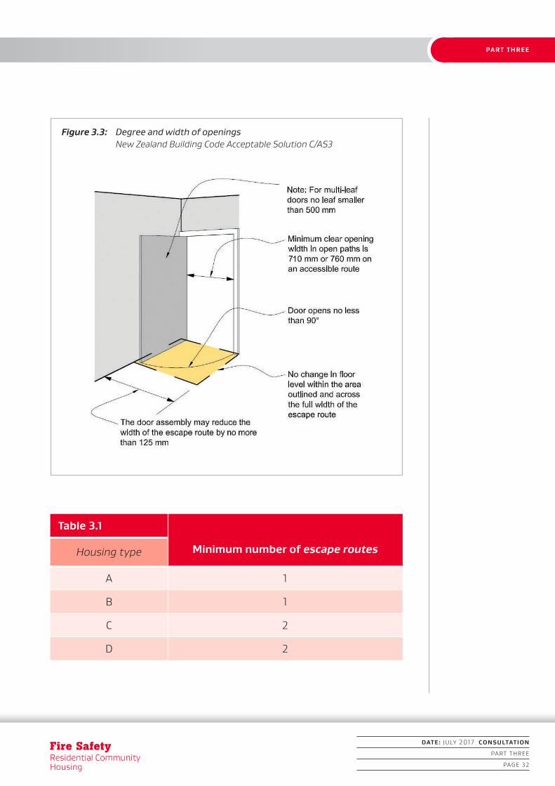
3.2.5 Degree and width of opening
Doors on escape routes shall satisfy the following requirements (see Figure 3.3):
(a) they shall provide a clear opening width of no less than that stipulated in Table 3.2; and
(b) final exit doors shall not reduce a clear exitway or corridor width required by Table 3.2 by more than 125 mm; and
(c) they shall open at no less than 90 degrees; and
(d) they shall open onto a floor area that is on the same level on both sides of the door for no less than the arc of the door swing.
3.2.6 Door opening forces
Door opening forces shall comply with NZBC Clause D1 and Acceptable Solution C/AS3.
3.2.7 Hold-open devices
Detector-activated hold-open devices may be fitted to fire doors or smoke control doors if these are required due to the volume of residents using the doors.
3.3 Door signs
3.3.1
All fire doors and smoke control doors shall have signs complying with NZBC Clause F8.
1. INTRODUCTION
Fire SafetyResidential Community Housing
DATE: JULY 2017 CONSULTATION
PART THREE
PAGE 32
PART THREE
Table 3.1
Housing type Minimum number of escape routes
A 1
B 1
C 2
D 2
Figure 3.3: Degree and width of openings New Zealand Building Code Acceptable Solution C/AS3

1. INTRODUCTION
DATE: JULY 2017 CONSULTATION
PART THREE
PAGE 33
PART THREE
Table 3.2 Minimum clear width of escape routes (mm)
Housing type DoorExitways and
corridors
A 710 900
B 760 1000
C 760 1000
D 860 1200
Notes:
Doors and escape routes that beds will need to pass through during evacuation shall be of sufficient width to allow the passage of a bed and essential life support equipment. Due consideration should be given to the requirements of NZBC Clause D.

DRAFT DESIGN GUIDE
DATE: JULY 2017 CONSULTATION
PART FOUR
PAGE 34
PART FOUR
Fire SafetyResidential Community Housing
Part 4: Control of internal fire and smoke spread
4.1 Fire separations for housing types
4.1.1 Housing type A and sprinklered type B
Where a single firecell is permitted for housing type A and sprinkler-protected type B, these buildings may consist of a single firecell and be fire separated from other property and from household units with fire separations with an FRR of 30/30/30.
4.1.2 Housing types B, C and D
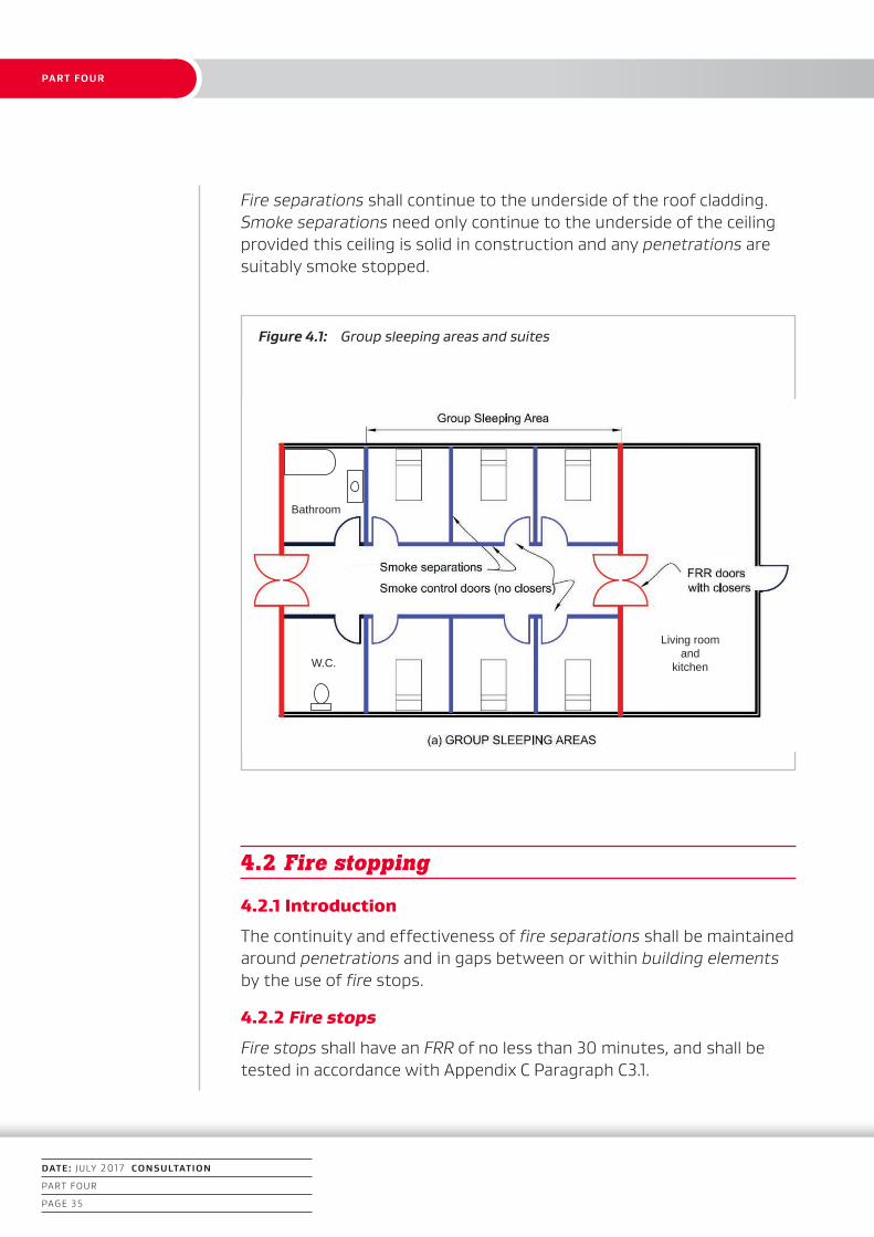
Where a minimum of two firecells is required for housing types B (non-sprinkler protected), C and D, in addition to the requirements of Paragraph 4.1.1 a fire separation with an FRR of 30/30/30 shall be provided to separate the sleeping area firecell from non-sleeping area firecell (see Figure 4.1).
The non-sleeping area firecell will contain communal service functions such as day, living and dining rooms as well as kitchens and storage areas.
The sleeping area firecell will contain a maximum of six beds. This firecell is defined as a group sleeping area.
4.1.3 Group sleeping areas
Group sleeping areas in housing types B, C and D shall contain no more than six beds and shall be fire separated from non-sleeping areas by an FRR of 30/30/30.
4.1.4 Subdivision of group sleeping areas
The sleeping areas of housing types B, C and D may be subdivided with full height smoke separations including smoke control doors that do not need to be fitted with self-closers. Direct support functions such as bathrooms may be included within the group sleeping area firecell (see Figure 4.1).
Communal service functions (see Paragraph 4.1.2), shall not be located within a sleeping area firecell and shall be separated from the sleeping area firecell with an FRR of 30/30/30 (see Figure 4.1).
1. INTRODUCTION
DATE: JULY 2017 CONSULTATION
PART FOUR
PAGE 35
PART FOUR
Fire separations shall continue to the underside of the roof cladding. Smoke separations need only continue to the underside of the ceiling provided this ceiling is solid in construction and any penetrations are suitably smoke stopped.
Figure 4.1: Group sleeping areas and suites
4.2 Fire stopping
4.2.1 Introduction
The continuity and effectiveness of fire separations shall be maintained around penetrations and in gaps between or within building elements by the use of fire stops.
4.2.2 Fire stops
Fire stops shall have an FRR of no less than 30 minutes, and shall be tested in accordance with Appendix C Paragraph C3.1.
Bathroom
Living roomand
kitchenW.C.

1. INTRODUCTION
Fire SafetyResidential Community Housing
DATE: JULY 2017 CONSULTATION
PART FOUR
PAGE 36
PART FOUR
4.2.3
Fire stops and methods of installation shall be identical to those of the prototype used in tests to establish their FRR.
4.2.4
The material selected for use as fire stops shall have been tested for the type and size of the gap or penetration, and for the type of material and construction used in the fire separation.
4.2.5
A fire stop for a penetration is not required to have an insulation rating if means are provided to keep combustible materials at a distance of 300 mm from the penetration and the fire stop to prevent ignition.
4.3 Firecell construction
4.3.1
Each of the building elements enclosing the firecell shall achieve an FRR of no less than [(30)/30/30].
4.3.2
Fire and smoke separations shall have no openings other than:
(a) for closures such as doorsets, (see Paragraphs 4.3.14 to 4.3.16) and
(b) Penetrations complying with Paragraphs 4.2.2 to 4.2.5.
4.3.3
Firecell and smokecell effectiveness shall be maintained by ensuring the continuity of fire and smoke separations at separation junctions, and around joints where closures, protected shafts and penetrations occur.
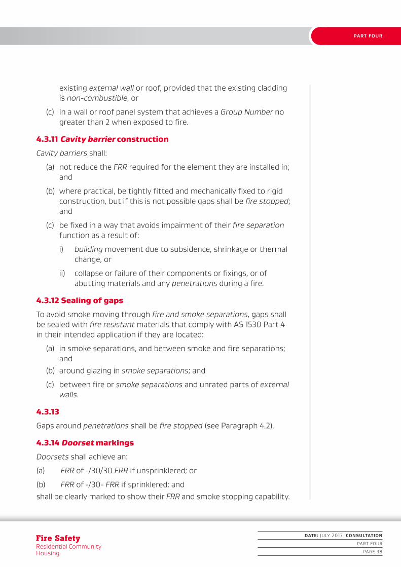
4.3.4 Junctions of fire separations
Where fire separations meet other fire separations or fire-rated parts of external walls, they shall either be bonded together or have the full length of the junction be fire stopped (see Figures 4.2 and 4.3).
4.3.5 Junctions with roof
Vertical fire separations and external walls shall end as close as possible to the external roof cladding and primary elements providing roof support, with any gaps fully fire stopped (see Figures 4.2 and 4.3).

1. INTRODUCTION
DATE: JULY 2017 CONSULTATION
PART FOUR
PAGE 37
PART FOUR
4.3.6 Ceiling space firecells
In housing types C and D the ceiling space may be constructed as a separate firecell above the firecells below, provided that the ceiling is a fire separation rated from below. In this situation vertical fire separations in the firecells below may terminate at the ceiling.
4.3.7 Concealed spaces
The spread of fire in concealed spaces and cavities shall be avoided by ensuring that extensive voids do not pass from one firecell to another, and by blocking off smaller voids with cavity barriers or, where appropriate, by using fire stops.
4.3.8 Subfloor spaces
In buildings with an unoccupied subfloor space between the ground and lowest floor the FRR of that floor shall be in accordance with Paragraph 2.3, however no FRR is required if the following conditions are satisfied:
(a) vertical fire separations and external walls extend down to ground level and enclose the space; and
(b) access is available only for intermittent servicing of plumbing, drainage or other static services; and
(c) the space is not used for storage and does not contain any installation such as machinery or heating appliances that could create a fire hazard, except when fire separated from the rest of the subfloor space.
4.3.9 Cavity barriers between walls and floors
Any concealed space that may be a path for fire spread within internal walls or floors that are fire separations, or within external walls, shall have cavity barriers or shall be fire stopped at all common junctions.
4.3.10 Exceptions to cavity barrier requirements
Cavity barriers are not required in the following circumstances:
(a) below a floor next to the ground if the concealed space is:
i) less than 1.0 m in height, or
ii) not normally accessed and has no openings litter can accumulate in, or
(b) if the concealed space results from the over-cladding of an
1. INTRODUCTION
Fire SafetyResidential Community Housing
DATE: JULY 2017 CONSULTATION
PART FOUR
PAGE 38
PART FOUR
existing external wall or roof, provided that the existing cladding is non-combustible, or
(c) in a wall or roof panel system that achieves a Group Number no greater than 2 when exposed to fire.
4.3.11 Cavity barrier construction
Cavity barriers shall:
(a) not reduce the FRR required for the element they are installed in; and
(b) where practical, be tightly fitted and mechanically fixed to rigid construction, but if this is not possible gaps shall be fire stopped; and
(c) be fixed in a way that avoids impairment of their fire separation function as a result of:
i) building movement due to subsidence, shrinkage or thermal change, or
ii) collapse or failure of their components or fixings, or of abutting materials and any penetrations during a fire.
4.3.12 Sealing of gaps
To avoid smoke moving through fire and smoke separations, gaps shall be sealed with fire resistant materials that comply with AS 1530 Part 4 in their intended application if they are located:
(a) in smoke separations, and between smoke and fire separations; and
(b) around glazing in smoke separations; and
(c) between fire or smoke separations and unrated parts of external walls.
4.3.13
Gaps around penetrations shall be fire stopped (see Paragraph 4.2).
4.3.14 Doorset markings
Doorsets shall achieve an:
(a) FRR of -/30/30 FRR if unsprinklered; or
(b) FRR of -/30- FRR if sprinklered; andshall be clearly marked to show their FRR and smoke stopping capability.

1. INTRODUCTION
DATE: JULY 2017 CONSULTATION
PART FOUR
PAGE 39
PART FOUR
4.3.15 Smoke control doors
Smoke control doors complying with Appendix C Paragraph C5.1.2 shall be provided in housing types C and D if the group sleeping area firecell is subdivided with full height partitions (see Paragraph 4.1.4).
4.3.16
Doorsets that are required to be fire doors shall comply with Appendix C Paragraph C5.1.1 and the smoke control capability outlined in Paragraph C5.1.2. Vision panels that are required in fire doors (see Paragraph 3.2) shall have fire resistant glazing with the same integrity rating as the door, and the door assembly shall be installed in accordance with Paragraph 3.2 and Appendix C.
4.4 Surface finishes
4.4.1 Foamed plastics
Foamed plastic building materials and exposed combustible insulating materials shall not be used in residential community housing.
4.4.2 Suspended flexible fabrics
When tested to AS 1530 Part 2, suspended flexible fabrics shall, within all occupied spaces:
(a) have a flammability index of no greater than 12; and
(b) when used as underlay to roofing or exterior cladding that is exposed to view, have a flammability index of no greater than 5.

1. INTRODUCTION
Fire SafetyResidential Community Housing
DATE: JULY 2017 CONSULTATION
PART FOUR
PAGE 40
PART FOUR
Figure 4.2: Junctions of fire separations – 1 New Zealand Building Code Acceptable Solution C/AS3
1. INTRODUCTION
DATE: JULY 2017 CONSULTATION
PART FOUR
PAGE 41
PART FOUR
Figure 4.3: Junctions of fire separations – 2 New Zealand Building Code Acceptable Solution C/AS3

DRAFT DESIGN GUIDEDRAFT DESIGN GUIDE
DATE: JULY 2017 CONSULTATION
PART FIVE
PAGE 42
PART FIVE
Fire SafetyResidential Community Housing
Part 5: Control of external fire spread
5.1 Fire resistance ratings (FRR)
5.1.1
External walls shall have an FRR of no less than 30/30/30 in the following circumstances:
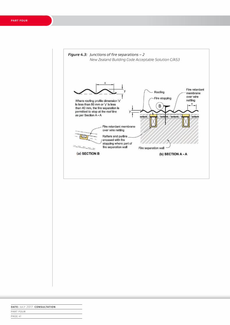
(a) outbuildings, single unit dwellings and attached, side-by-side multi-unit dwellings where part of the external wall is less than 1.0 m and less than 90º from the relevant boundary (see Figure 5.1). The wall shall be fire rated to protect from both directions; and
(b) multi-unit dwellings located one above the other where the external wall is less than 5.0 m from the relevant boundary. If there are windows more than 1.0 m from the relevant boundary in a household unit wall requiring an FRR, the windows do not need to be fire rated.
Where the building is protected by a sprinkler system complying with NZS 4541 external walls do not require an FRR.
5.1.2
When the unprotected area of an external wall is permitted to be 100% but the primary elements in the line of that wall are required to be fire rated, the rating of those primary elements shall be the life rating 30 minutes’ FRR.
5.2 Firecells on the same property
5.2.1
Separate household units in the same building shall be separated with an FRR of no less than 30/30/30. The wall shall be fire rated from both directions.
5.2.2
For separate structures that have a sleeping use on the same property, where the separation of external walls is less than 1.0 m apart, at least

1. INTRODUCTION
DATE: JULY 2017 CONSULTATION
PART FIVE
PAGE 43
PART FIVE
one external wall shall have an FRR of no less than 30/30/30. The wall shall be fire rated from both directions.
5.2.3 Notional boundaries – firecells on the same property
For firecells under common ownership in the same building, or in separate buildings on the same property, a notional boundary shall be used instead of the relevant boundary. In such cases, when applying Paragraph 5.1 the words relevant boundary shall be interpreted as notional boundary.
5.3 Roof projections
5.3.1
Where the external wall is required to have an FRR, the eaves projection shall either have an FRR of 30/30/30 or the wall shall be extended to the underside of the roof.
5.3.2
Where roof eaves extend from an otherwise unrated external wall to within 650 mm of the relevant boundary, the total eaves construction and the external wall they project from shall have an FRR of no less than 30/30/30.
5.4 Protection from a lower roof in multi-unit dwellings
5.4.1
Fire spread from a roof close to, and lower than, an external wall of an attached sleeping unit or attached building on other property shall be prevented by providing an FRR of 30/30/30 to either:
(a) the part of the roof within 5.0 m horizontally of the wall; or
(b) any part of the wall within 9.0 m vertically of the roof.
5.4.2
Fire rating of the roof is not required if the household unit is protected with a sprinkler system complying with NZS 4515 or NZS 4541 (see Figure 5.2).

1. INTRODUCTION
Fire SafetyResidential Community Housing
DATE: JULY 2017 CONSULTATION
PART FIVE
PAGE 44
PART FIVE
5.5 Exterior surface finishes
External wall cladding systems shall be tested to the standard test described in Appendix C Paragraph C6.1 and the peak rate of heat release and the total heat released shall not exceed the limits given in Table 5.1.
These requirements do not apply if surface finishes are no more than 1 mm in thickness and applied directly to a non-combustible substrate.
5.6 Carports and similar construction
A carport is permitted to have walls and roof with 100% unprotected area provided that all the following conditions are met:
(a) at least two sides are completely open to the environment; and
(b) the carport and adjacent building are under the same ownership; and
(c) for a roof plan area of no more than 40 m², no part of the roof is closer than 0.3 m to a relevant boundary.

1. INTRODUCTION
DATE: JULY 2017 CONSULTATION
PART FIVE
PAGE 45
PART FIVE
Table 5.1 Requirements for external wall claddings
Column A Column A Column C Column D
Distance to relevant boundary (angle between wall and boudary is less than 90º)
Less than 1.0 m
Distance greater than or equal to 1.0 m and building
height less than or
equal to 10m
Distance greater than or equal to 1.0 m and building
height greater than 10m
UnsprinkleredSprinklered to NZS 4515
Peak heat release
rate (kW/m²)
100No
requirement150
No requirement
Total heat released (MJ/m²)
25No
requirement50
No requirement
Notes:
Table 5.1 applies to seperate buildings. It does not apply to household units within the same building whether they are side by side or one above the other.
1. INTRODUCTION
Fire SafetyResidential Community Housing
DATE: JULY 2017 CONSULTATION
PART FIVE
PAGE 46
PART FIVE
Figure 5.1: Fire rating of external walls New Zealand Building Code Acceptable Solution C/AS3
1m1m
1m
1m
Boundary
Fire rating
Fire rating

1. INTRODUCTION
DATE: JULY 2017 CONSULTATION
PART FIVE
PAGE 47
PART FIVE
Figure 5.2: External walls and roof, vertical fire spread New Zealand Building Code Acceptable Solution C/AS3

DRAFT DESIGN GUIDEDRAFT DESIGN GUIDEDRAFT DESIGN GUIDE
DATE: JULY 2017 CONSULTATION
PART SIX
PAGE 48
PART SIX
Fire SafetyResidential Community Housing
Part 6: Firefighting
6.1 Fire Service vehicular access
6.1.1
If buildings that contain multi-unit dwellings with more than two units are located remotely from the street boundaries of a property, pavements situated on the property and necessary to be used for vehicular access to a hard-standing within:
i) 75 m of any point in any unit contained in the building except if there is a sprinkler system complying with NZS 4515, and
ii) 20 m of any inlets to fire sprinkler or building fire hydrant systems, shall:
(a) be able to withstand a laden weight of up to 25 tonnes with an axle load of 8 tonnes or have a load-bearing capacity of no less than the public roadway serving the property, whichever is the lower; and
(b) be trafficable in all weathers; and
(c) have a minimum width of 4.0 m; and
(d) provide a clear passageway of no less than 3.5 m in width and 4.0 m in height at site entrances, internal entrances and between buildings.
DRAFT DESIGN GUIDEDRAFT DESIGN GUIDEDRAFT DESIGN GUIDEDRAFT DESIGN GUIDE
DATE: JULY 2017 CONSULTATION
PART SEVEN
PAGE 49
PART SEVEN
Part 7: Prevention of fire occurringThe design, construction and/or installation of certain types of fixed appliances using controlled combustion and other fixed equipment is specified as follows.
7.1 Solid fuel appliances
7.1.1
AS/NZS 2918, with the modifications given in Paragraph 7.1.2, is an Acceptable Solution for the installation of:
(a) domestic solid fuel burning appliances installed in either domestic or commercial situations; and
(b) flue systems.
A normative Appendix is an integral part of this Standard.
7.1.2
Modifications to AS/NZS 2918Delete Paragraph 3.8 of this Standard and substitute the following:
“3.8 Seismic restraintThe appliance and the floor protector shall be mechanically fixed to the floor itself. The test seismic force shall be taken as the application of a horizontal force equal to 0.40 times the appliance weight acting in any direction at the mid height of the combustion chamber. The appliance shall not move, tilt or be dislodged from its installed position during the application of the test force. The weight of the flue system and a wetback, if fitted, shall not be included in the test.”
Delete Section 7 and substitute the following:
“7.1 VentilationVentilation shall be in accordance with Acceptable Solution G4/AS1.7.2 Water heating equipment. Water heating appliances installed in conjunction with the heating appliance shall be vented and shall comply with Acceptable Solution G12/AS1.”
1. INTRODUCTION
Fire SafetyResidential Community Housing
DATE: JULY 2017 CONSULTATION
PART SEVEN
PAGE 50
PART SEVEN
7.2 Gas-burning appliances
7.2.1
For gas-burning appliances AS/NZS 5601.1 sections 6.7, 6.8 and 6.9 and Appendix H of this Standard are Acceptable Solutions for the construction and installation of flues, and sections 5.11, 6.2, 6.3 and 6.10 are Acceptable Solutions for the installation of appliances, with the modifications given in Paragraph 7.2.2.
7.2.2
Modifications to AS/NZS 5601.1
Delete Paragraph 6.2.11 and substitute the following:
“6.2.11 Seismic restraint
Seismic restraint of appliances installed in buildings shall be designed in accordance with B1/VM1 Paragraphs 2.0 and 13.0.”
Add a Note to Paragraph 6.4 as follows:
“Note: Ventilation requirements are contained in Acceptable Solution G4/AS1. The ventilation requirements of this Standard may exceed the performance requirements of NZBC G4.”
7.3 Oil-fired appliances
7.3.1
AS 1691, with the modifications given in Paragraph 7.3.2, is an Acceptable Solution for the installation of domestic oil-fired appliances.
7.3.2
Modifications to AS 1691
Delete Paragraph 2.2.3 and substitute the following:
“2.2.3 Electrical equipment
Electrical equipment shall comply with Acceptable Solution G9/AS1 or Verification Method G9/VM1.”
Delete “CSIRO durability Class 2 or better” from Paragraph 3.1.2 (b) and substitute “H5 treatment”.
Delete the Note to Paragraph 3.1.2 (d).

1. INTRODUCTION
DATE: JULY 2017 CONSULTATION
PART SEVEN
PAGE 51
PART SEVEN
Delete Paragraph 3.1.4 and substitute the following:
“3.1.4 Stability
The appliance shall be mechanically fixed to the building.
The test seismic force on the fuel tank shall be taken as the application of a horizontal force in kilograms numerically equal to 0.40 times the tank volume in litres acting at the centre of the tank. The test seismic force on the appliance shall be taken as the application of a horizontal force equal to 0.40 times the appliance operating weight acting at the centre of the appliance.
The appliance and the fuel tank shall resist their respective seismic forces with no significant movement.”
Delete the words “without specific approval” from Paragraph 3.2.8 (b).
Delete Paragraph 5.1.1.
Add a Note to Paragraph 5.2.2:
“Note: Refer to Acceptable Solution G4/AS1 for ventilation requirements.”
7.3.3
AS/NZS 2918 Sections 2 and 4 are also Acceptable Solutions for the installation of flues for domestic oil-fired appliances.
7.4 Recessed luminaires
7.4.1
Recessed luminaires (downlights) shall be one of the following types, as specified in AS/NZS 60598.2.2:
(a) IC-F, or
(b) IC, or
(c) CA-80 or
(d) CA-135.
Full compliance with this requirement can only be achieved if the luminaire is installed in accordance with AS/NZS 60598.2.2.

1. INTRODUCTION
Fire SafetyResidential Community Housing
DATE: JULY 2017 CONSULTATION
PART SEVEN
PAGE 52
PART SEVEN
7.5 Open fires
7.5.1 Chimneys
Chimneys shall be constructed in accordance with Table 7.1 and Figure 7.1. They shall have:
(a) fireplaces lined with fire bricks having a thickness of no less than 50 mm; and
(b) fireplace joints of non-combustible material and shall be sealed against air leakage; and
(c) chimney brickwork of no less than a single skin of brick 90 mm thick plus a 65 mm-thick layer of grout; and
(d) an expansion gap provided in chimneys containing flue liners. These flue liners shall be wrapped in a combustible material of thickness no less than 0.25 mm (eg heavy-quality building paper) to prevent the grout filling from bonding with the flue liner.
7.5.2
Cross-sectional areas of flues shall be no less than 0.03 m² for an open fireplace (see Figure 7.2).

1. INTRODUCTION
DATE: JULY 2017 CONSULTATION
PART SEVEN
PAGE 53
PART SEVEN
Figure 7.1: Chimney terms and dimensions New Zealand Building Code Acceptable Solution C/AS1
1. INTRODUCTION
Fire SafetyResidential Community Housing
DATE: JULY 2017 CONSULTATION
PART SEVEN
PAGE 54
PART SEVEN
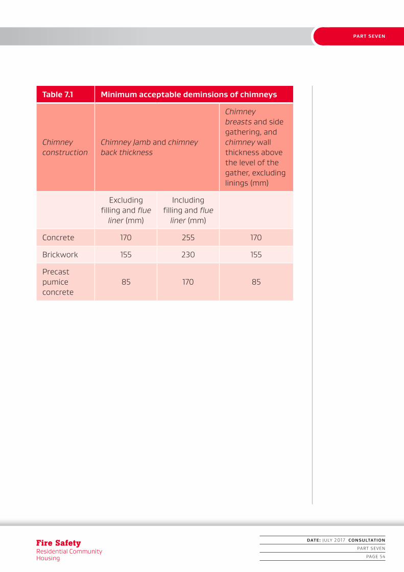
Table 7.1 Minimum acceptable deminsions of chimneys
Chimney construction
Chimney Jamb and chimney back thickness
Chimney breasts and side gathering, and chimney wall thickness above the level of the gather, excluding linings (mm)
Excluding filling and flue
liner (mm)
Including filling and flue
liner (mm)
Concrete 170 255 170
Brickwork 155 230 155
Precast pumice concrete
85 170 85
1. INTRODUCTION
DATE: JULY 2017 CONSULTATION
PART SEVEN
PAGE 55
PART SEVEN
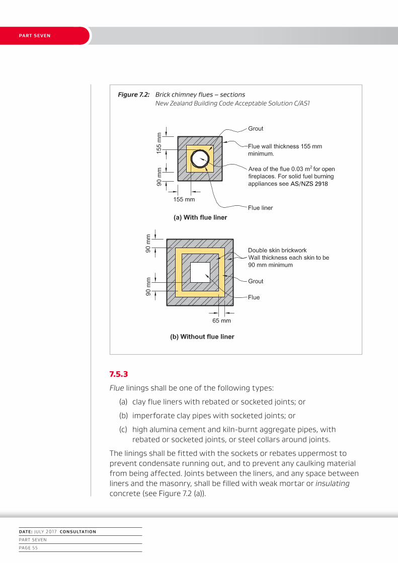
Figure 7.2: Brick chimney flues – sections New Zealand Building Code Acceptable Solution C/AS1
AS/NZS 2918
7.5.3
Flue linings shall be one of the following types:
(a) clay flue liners with rebated or socketed joints; or
(b) imperforate clay pipes with socketed joints; or
(c) high alumina cement and kiln-burnt aggregate pipes, with rebated or socketed joints, or steel collars around joints.
The linings shall be fitted with the sockets or rebates uppermost to prevent condensate running out, and to prevent any caulking material from being affected. Joints between the liners, and any space between liners and the masonry, shall be filled with weak mortar or insulating concrete (see Figure 7.2 (a)).
1. INTRODUCTION
Fire SafetyResidential Community Housing
DATE: JULY 2017 CONSULTATION
PART SEVEN
PAGE 56
PART SEVEN
7.5.4
Flue liners are not required for:
(a) brick chimneys if constructed of two 90 mm skins of brickwork with a 65 mm grout-filled gap between (see Figure 7.2 (b)); or
(b) ordinary concrete chimneys; or
(c) precast pumice concrete chimneys.
7.5.5
Clearance above roofs shall be in accordance with Figure 4.9 of AS/NZS 2918.
7.5.6
Every fireplace shall have a separate flue.
7.5.7
Flue joints shall be made of non-combustible material and sealed against air leakage.
7.5.8
Hearths for fireplaces shall:
(a) be constructed of fully grouted stones, bricks or concrete of no less than 50 mm total thickness; and
(b) extend no less than 230 mm on each side of the fireplace opening, and no less than 380 mm forward of the fireplace opening; and
(c) have no combustible material closer than the clearances given in Paragraph 7.5.8 (b) from the upper and lower surfaces of the hearth.
7.5.9
Clearances between a chimney and any combustible material (see Figure 7.3) shall be no less than:
(a) 200 mm at any opening in the flue, or at the fireplace opening; and
(b) 200 mm above or below the upper surface of the hearth, and 75 mm from the lower surface of the hearth.
1. INTRODUCTION
DATE: JULY 2017 CONSULTATION
PART SEVEN
PAGE 57
PART SEVEN
7.5.10
Hearth edges shall be separated from combustible material by insulating material with a minimum service operating temperature of 150°C.
7.5.11
A ventilated space of no less than 50 mm shall be provided between the outer face of a fireplace, chimney or flue and any combustible material.
7.5.12
AS/NZS 2918 Sections 2 and 4 are also Acceptable Solutions for the installation of flues from open fires.

1. INTRODUCTION
Fire SafetyResidential Community Housing
DATE: JULY 2017 CONSULTATION
PART SEVEN
PAGE 58
PART SEVEN
Chimney flue liner built of non-combustible material
Figure 7.3: Clearances between chimney and hearth, and combustible materials New Zealand Building Code Acceptable Solution C/AS1

DRAFT DESIGN GUIDEDESIGN GUIDE
APPENDICES
DRAFT DESIGN GUIDE
DATE: JULY 2017 CONSULTATION
APPENDICES
PAGE 59

1. INTRODUCTION
DATE: JULY 2017 CONSULTATION
APPENDICES
PAGE 60
APPENDICES
Fire SafetyResidential Community Housing
Appendix A (normative): Fire safety systems
A1.1 Fire alarm and sprinkler systems
A1.1.1
Fire alarm systems used in fire safety systems shall meet the requirements of Acceptable Solution F7/AS1. Fire sprinkler systems used in the fire safety systems shall, except where specified, also meet the requirements of Appendix B of this design guide.
A1.2 Requirements common to alarm systems
A1.2.1
Except for domestic smoke alarm systems and where otherwise specified, each fire alarm system, regardless of how it is activated, shall be able to communicate with the Fire Service in accordance with Acceptable Solution F7/AS1.
1. INTRODUCTION
DATE: JULY 2017 CONSULTATION
APPENDICES
PAGE 61
APPENDICES
Appendix B (normative): Fire sprinkler systems
B1.1 Introduction
B1.1.1
Wherever sprinklers are required by this Acceptable Solution they shall comply with the relevant New Zealand Standard, amended as shown in Paragraphs B2.1 and B3.1 and B4.1.
B2.1 Automatic fire sprinkler systems
B2.1.1
NZS 4541 is amended as follows:
Clause 103 Definitions
Sprinkler system A system including:
(a) to (i) No change.
(j) Delete.
(k) Delete.
(l) No change.
Clause 205 Delete entire clause.
Clause 209 Delete entire clause.
Clause 1203 Routine surveys
Clause 1203.1 Delete first two paragraphs and replace with:
“It is important that a sprinkler system at all times complies with this Standard as amended by Paragraph B2.1 of Appendix B in all respects. To ensure that building alterations, changes in process or storage patterns or progressive deterioration of system components do not prejudice system compliance, a comprehensive survey shall be carried out biennially at intervals not exceeding 28 months. Such surveys shall be carried out by an independent qualified person.”
1. INTRODUCTION
DATE: JULY 2017 CONSULTATION
APPENDICES
PAGE 62
APPENDICES
Fire SafetyResidential Community Housing
B3.1 Residential fire sprinkler systems
B3.1.1
NZS 4515 is amended as follows:
Clause 1.5 Definitions
Sprinkler system A system including:
(a) to (g) No change.
(h) Delete.
Clause 1.11 Delete entire clause.
Clause 2.1.2 Delete.
Clause 2.1.3 Delete.
B4.1 Sprinkler systems for houses
B4.1.1
NZS 4517

1. INTRODUCTION
DATE: JULY 2017 CONSULTATION
APPENDICES
PAGE 63
APPENDICES
Appendix C (normative): Test methods
C1.1 General
This Appendix contains test methods for confirming that specific building elements satisfy relevant provisions of this design guide. It includes both established standard tests and other test methods for building elements in situations where standard tests are unavailable.
If these specific building elements have been tested to a version of a Standard in force at the date of testing and a later version of that Standard has been incorporated by reference in this design guide, retesting is not required.
C2.1 Flammability of floor coverings
C2.1.1
Materials shall be assigned a critical radiant flux either:
(a) when tested to ISO 9239 Reaction to fire tests for flooring – Part 1: Determination of the burning behaviour using a radiant heat source, or
(b) by reference to NZBC Verification Method C/VM2, Appendix B Table B1.
C3.1 Flammability of suspended flexible fabrics and membrane structures
C3.1.1
Materials shall be assigned a flammability index when tested to AS 1530 Methods for fire tests on building materials, components and structures – Part 2: Test for flammability of materials.
C4.1 Fire resistance
C4.1.1
Primary and secondary elements, closures and fire stops shall be
1. INTRODUCTION
DATE: JULY 2017 CONSULTATION
APPENDICES
PAGE 64
APPENDICES
Fire SafetyResidential Community Housing
assigned a fire resistance rating FRR when tested to:
(a) AS 1530 Methods for fire tests on building materials, components and structures – Part 4: Fire resistance tests of elements of building construction, or
(b) NZS/BS 476 Fire tests on building materials and structures – Parts 21 and 22.
C4.1.2
Fire stops shall be tested:
(a) in circumstances representative of their use in service, paying due regard to the size of expected gaps to be fire stopped, and the nature of the fire separation within which they are to be used, and
(b) in accordance with AS 4072: Components for the protection of openings in fire resistant separating elements – Part 1: Service penetrations and control joints.
C5.1 Fire doors and smoke control doors
C5.1.1
Fire doors shall be evaluated in circumstances representative of their use in service, and shall comply with NZS 4520 Fire-resistant doorsets.
C5.1.2 Smoke control doors
A door shall be deemed to be a smoke control door if, in addition to the requirements in this Acceptable Solution for smoke control doors:
(a) the door is a fire door that is fitted with appropriate smoke seals, or if:
(b) it is constructed with solid core leaves. Solid timber core leaves, when used, shall have a leaf thickness of no less than 35 mm, and
(c) it is provided with smoke seals as required by this Acceptable Solution. Smoke seals shall be in continuous contact with the mating element, and located so interruption by hardware is limited, and
(d) the frames are constructed of timber, and the jambs are no less than 30 mm thick, and
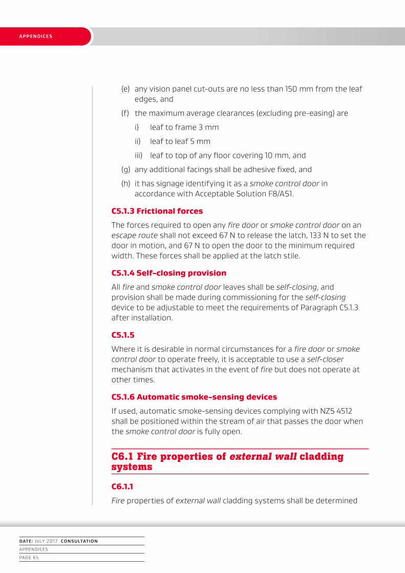
1. INTRODUCTION
DATE: JULY 2017 CONSULTATION
APPENDICES
PAGE 65
APPENDICES
(e) any vision panel cut-outs are no less than 150 mm from the leaf edges, and
(f) the maximum average clearances (excluding pre-easing) are
i) leaf to frame 3 mm
ii) leaf to leaf 5 mm
iii) leaf to top of any floor covering 10 mm, and
(g) any additional facings shall be adhesive fixed, and
(h) it has signage identifying it as a smoke control door in accordance with Acceptable Solution F8/AS1.
C5.1.3 Frictional forces
The forces required to open any fire door or smoke control door on an escape route shall not exceed 67 N to release the latch, 133 N to set the door in motion, and 67 N to open the door to the minimum required width. These forces shall be applied at the latch stile.
C5.1.4 Self-closing provision
All fire and smoke control door leaves shall be self-closing, and provision shall be made during commissioning for the self-closing device to be adjustable to meet the requirements of Paragraph C5.1.3 after installation.
C5.1.5
Where it is desirable in normal circumstances for a fire door or smoke control door to operate freely, it is acceptable to use a self-closer mechanism that activates in the event of fire but does not operate at other times.
C5.1.6 Automatic smoke-sensing devices
If used, automatic smoke-sensing devices complying with NZS 4512 shall be positioned within the stream of air that passes the door when the smoke control door is fully open.
C6.1 Fire properties of external wall cladding systems
C6.1.1
Fire properties of external wall cladding systems shall be determined
1. INTRODUCTION
DATE: JULY 2017 CONSULTATION
APPENDICES
PAGE 66
APPENDICES
Fire SafetyResidential Community Housing
in accordance with: ISO 5660 Reaction-to-fire tests – Heat release, smoke production and mass loss rate – Part 1: Heat release rate (cone calorimeter method).
C6.1.2
In addition to meeting the general requirements of ISO 5660 Part 1, testing shall be in accordance with the following specific requirements:
(a) an applied external heat flux of 50 kW/m²
(b) a 15-minute test
(c) the total heat release shall be measured from the start of the test
(d) the sample orientation shall be horizontal, and
(e) the ignition shall be initiated by the external spark igniter.
C6.1.3
Timber claddings that have a fire retardant treatment incorporated in or applied to them shall undergo accelerated weathering described in ASTM D 2898 Method B with the water flow rate from Method A before being tested in accordance with the requirements of Paragraph C6.1.1.
C6.1.4
External wall cladding systems which comprise only materials which individually are classified as non-combustible may be deemed to satisfy all the requirements of Paragraph 5.5.
C6.1.5
Claddings incorporating a metal facing with a melting point of less than 750°C covering a combustible core or insulant shall be tested as described in Paragraph C6.1.2 without the metal facing present.
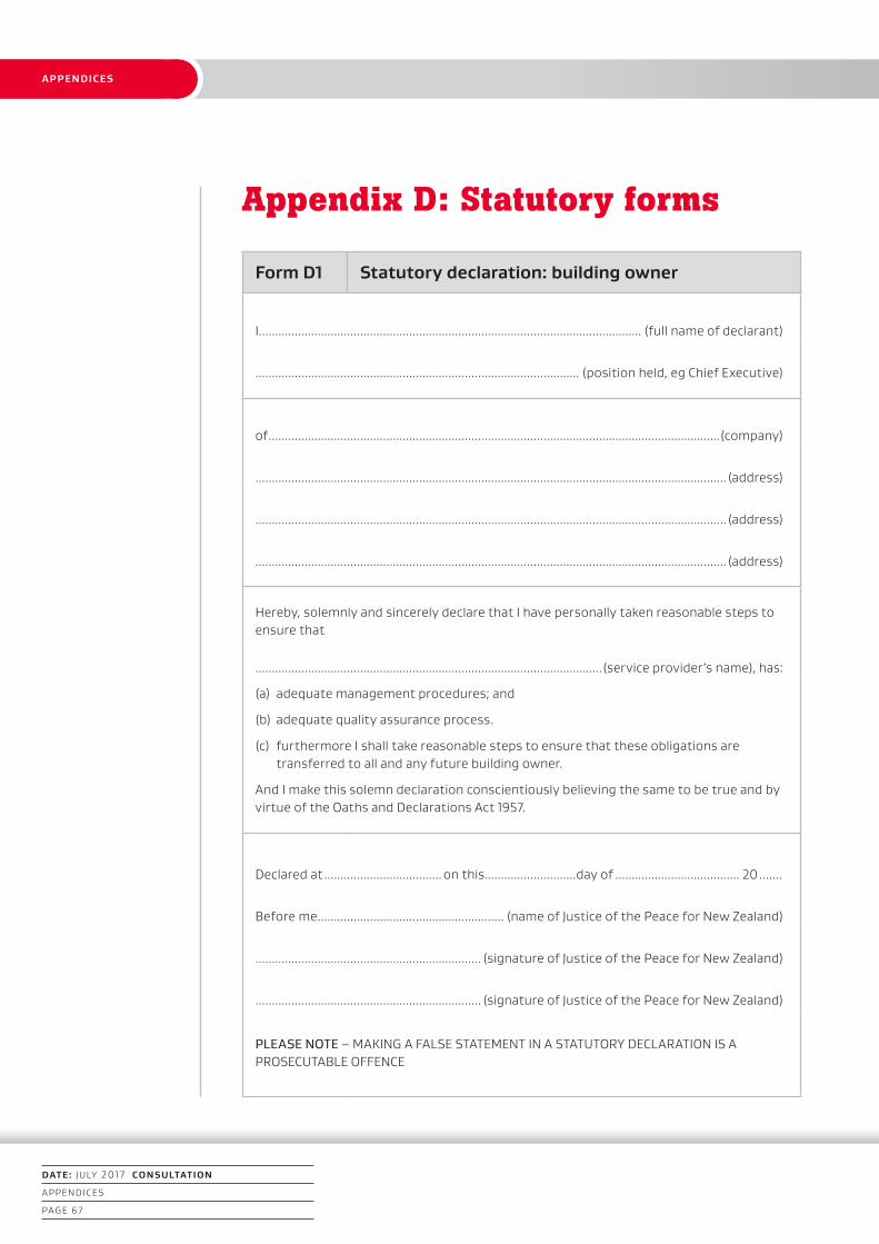
1. INTRODUCTION
DATE: JULY 2017 CONSULTATION
APPENDICES
PAGE 67
APPENDICES
Appendix D: Statutory forms
Form D1 Statutory declaration: building owner
I..................................................................................................................... (full name of declarant)
................................................................................................... (position held, eg Chief Executive)
of ..........................................................................................................................................(company)
................................................................................................................................................ (address)
................................................................................................................................................ (address)
................................................................................................................................................ (address)
Hereby, solemnly and sincerely declare that I have personally taken reasonable steps to ensure that
..........................................................................................................(service provider’s name), has:
(a) adequate management procedures; and
(b) adequate quality assurance process.
(c) furthermore I shall take reasonable steps to ensure that these obligations are transferred to all and any future building owner.
And I make this solemn declaration conscientiously believing the same to be true and by virtue of the Oaths and Declarations Act 1957.
Declared at .................................... on this............................day of ...................................... 20 .......
Before me ......................................................... (name of Justice of the Peace for New Zealand)
..................................................................... (signature of Justice of the Peace for New Zealand)
..................................................................... (signature of Justice of the Peace for New Zealand)
PLEASE NOTE – MAKING A FALSE STATEMENT IN A STATUTORY DECLARATION IS A PROSECUTABLE OFFENCE

1. INTRODUCTION
DATE: JULY 2017 CONSULTATION
APPENDICES
PAGE 68
APPENDICES
Fire SafetyResidential Community Housing
Form D2 Statutory declaration: service owner
I..................................................................................................................... (full name of declarant)
......................................................................(position held, eg business owner/Chief Executive)
of ..........................................................................................................................................(company)
................................................................................................................................................ (address)
................................................................................................................................................ (address)
................................................................................................................................................ (address)
Hereby, solemnly and sincerely declare that I have personally taken reasonable steps to ensure that
............................................................................................ (name of service provider’s business), has documented quality assurance processes to ensure that:
(a) the documented management procedures are, and shall remain to be, adequate for the building’s intended use, and
(b) the service provider/s understand/s the documented management procedures, and
(c) the service provider/s is/are working within the limitations of the documented management procedures.
(d) furthermore I shall take reasonable steps to ensure that these obligations are transferred to all and any future service provider.
And I make this solemn declaration conscientiously believing the same to be true and by virtue of the Oaths and Declarations Act 1957.
Declared at .................................... on this............................day of ...................................... 20 .......
Before me ......................................................... (name of Justice of the Peace for New Zealand)
..................................................................... (signature of Justice of the Peace for New Zealand)
..................................................................... (signature of Justice of the Peace for New Zealand)
PLEASE NOTE – MAKING A FALSE STATEMENT IN A STATUTORY DECLARATION IS A PROSECUTABLE OFFENCE