DRAFT AC6.E Sugar Dispenser SERVICE Manual Dec...
28
AC6.E Portion-Controlled Sugar Dispenser Service Manual For all 1, 3, 4 and 5 Button Models D-19-034
Transcript of DRAFT AC6.E Sugar Dispenser SERVICE Manual Dec...

AC6.E Portion-Controlled
Sugar Dispenser
Service Manual
For all 1, 3, 4 and 5 Button Models D-19-034

2
A. C. Dispensing Equipment Inc. 100 Dispensing Way Lower Sackville, NS B4C 4H2 Canada
Technical Assistance Center: 1-888-777-9990 or 1-902-865-9602
Service Email: [email protected]
Parts Email: [email protected]
Web: www.sureshotdispensing.com AC6.E Certifications:
D-19-034
TABLE OF CONTENTS
Specifications 3 Electrical Requirements 3 Safety Precautions 3 Inspection for Damage 3
1 SET UP Uncrating the Dispenser 4 Reshipment 4 Installation of Dispenser 4 Sugar Supplies - Storage 5 Hopper Strainers 5
2 OPERATIONS Clean before first use 5 Starting the Dispenser 5 Loading the Dispenser 5 To Dispense Sugar 6 Button Panels 6 Maintenance – Plunger & Plunger Tip 6 Maintenance - Quantity Adjustments 6 Tube Replacement & Maintenance 6 Tube Changing Procedure 7 ClumpBuster 8
3 CLEANING Cleaning – Catch Tray 9 Cleaning – The Exterior 9 Cleaning – The Sugar Hopper 9 Cleaning – The Valve Assembly 10 Cleaning – The Valve Area 11 Schedule – Cleaning & Maintenance 11
4 TECHNICAL SERVICE Install Legs 12Remove Hopper 12Remove Dispense Tube 13Remove Bottom Rear Cover 13Remove Valve Assembly 13Remove Dispensing Solenoid Assembly 14Remove Circuit Board 15Remove Electrical Panel 15Remove Circuit Breaker 15Remove Transformer 16
5 CHECKS AND ADJUSTMENTS AC Outlet for 115 VAC 17Output from Transformer 17Output from Circuit Board 17Testing Button Panel Continuity 18Continuity Check for Circuit Breaker 18Calibration Procedure – dispense buttons 19
6 DRAWINGS Wiring Diagram 120 VAC 20Wiring Diagram 240 VAC 21General Assembly 22
7 PARTS LIST 23
8 TROUBLESHOOTING 25 9 WARRANTY 27

3
AC6.E GRANULAR SUGAR DISPENSER
IMPORTANT: Read this Manual now and retain it for future reference The SureShot Dispensing Systems® AC6.E dispenser automatically dispenses controlled portions of granular white sugar. Our factory has pre-configured your dispenser to deliver sugar quantities specified by your company. To dispense, push the appropriate button on the front of the dispenser. The sugar is contained in the sanitary hopper compartment in the top of the dispenser. Specifications Capacity: 6 lbs / 2.72 kg Weight: 15 lbs (empty dispenser) Dimensions: L x W x H: 11” x 7” x 22¼” Electrical Requirements
• The power requirement is: 115 VAC, 4 Amp, 1 ph, 60 Hz. • The power cord is furnished with a UL-approved 3-prong attachment plug. This plug is designed
to fit a receptacle with provisions for a grounding pin. The dispenser includes a microcontroller and must be operated on grounded electrical wiring at all times. Failure to do so will void the Warranty.
• Electrical servicing must be done by a qualified technician. The Warranty will be null and void if the dispenser is serviced by unqualified personnel.
Inspection for Damage
• When you receive the dispenser, inspect the exterior of the shipping container for damage. Note any damage in detail.
• Uncrate the dispenser at once (see instructions on page 4) and examine it for damage. Report any damage to the transportation company and file a claim for damages promptly. Do not discard the packaging.
• Your immediate inspection protects you against loss since A.C. Dispensing Equipment Inc. is not responsible for damages incurred during shipment
• Notify A.C. Dispensing Equipment Inc. No returns will be accepted without prior approval. Obtain an authorized return number by contacting A. C. Dispensing Equipment Inc. Technical Assistance Center at 1-888-777-9990 or 1-902-865-9602.
Safety Precautions • Always plug the dispenser into an approved electrical outlet. • The dispenser includes a microcontroller and must be operated on grounded electrical
wiring at all times. • Unplug the dispenser from its electrical source before servicing. • Do not immerse the dispenser in water. • Over-tightening screws may cause damage to connecting pins inside the machine. • Observe all safety precautions with this dispenser that you would with any electrical
appliance.

4
1. SETUP Uncrating the Dispenser 1. Remove the dispenser from the packaging: unfold the packing material and lift the dispenser out of the box. 2. Prior to use, read this Operations Manual and store it for future reference. 3. Remove the plastic protective covering from the stainless steel exterior of the dispenser, by peeling it off. Hold the dispenser firmly at the top and peel in sections from top to bottom. 4. Turn the black valve thumbscrew counter-clockwise to open the valve door and ensure that the dispense tube is centered in the dispense valve. 5. Close the valve door and turn the black valve thumbscrew clockwise to secure it. 6. Cut the tube so that it is no longer than ¼” below the bottom of the dispense valve. 7. Remove the packing tape holding the catch tray in place at the dispenser front. See Figure below. 8. Confirm that the dispenser hopper contains the bottom stainless steel strainer and the optional top strainer (if your dispenser is a model that uses the top strainer). Reshipment Packaging for shipment is done in the reverse order of uncrating. If packaging is not available, it can be purchased locally, or from our factory by request. Any damage occurring in transit of the returned goods and caused by improper packaging is not considered a defect covered by warranty. Installation and Location of the Dispenser in your Business
• Place the dispenser where it will best serve your operation. • Do not place the dispenser too close to a source of heat or moisture. • The dispenser must be placed on a level surface. • Counters, platforms, or shelves should be strong enough to support the dispenser and a full
product load. • Leave clear space around the dispenser, approximately one inch on all sides. • Do not remove the legs from the dispenser or allow it to sit flat on the counter. Make sure the
rubber feet at the ends of the legs of the dispenser are in place. If one has loosened during shipping, insert it. You may use a small screwdriver to tuck the rubber into the holes. Contact A.C. Dispensing Equipment Inc. for replacement feet at 1-888-777-9990 or 1-902-865-9602.
• Place the dispenser at the appropriate serving height so that staff drawing product from the dispenser can operate the buttons and easily place and remove cups.
5
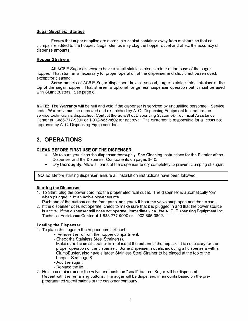
Sugar Supplies: Storage Ensure that sugar supplies are stored in a sealed container away from moisture so that no clumps are added to the hopper. Sugar clumps may clog the hopper outlet and affect the accuracy of dispense amounts. Hopper Strainers All AC6.E Sugar dispensers have a small stainless steel strainer at the base of the sugar hopper. That strainer is necessary for proper operation of the dispenser and should not be removed, except for cleaning. Some models of AC6.E Sugar dispensers have a second, larger stainless steel strainer at the top of the sugar hopper. That strainer is optional for general dispenser operation but it must be used with ClumpBusters. See page 8. NOTE: The Warranty will be null and void if the dispenser is serviced by unqualified personnel. Service under Warranty must be approved and dispatched by A. C. Dispensing Equipment Inc. before the service technician is dispatched. Contact the SureShot Dispensing Systems® Technical Assistance Center at 1-888-777-9990 or 1-902-865-9602 for approval. The customer is responsible for all costs not approved by A. C. Dispensing Equipment Inc.
2. OPERATIONS CLEAN BEFORE FIRST USE OF THE DISPENSER
• Make sure you clean the dispenser thoroughly. See Cleaning Instructions for the Exterior of the Dispenser and the Dispenser Components on pages 9-10.
• Dry thoroughly. Allow all parts of the dispenser to dry completely to prevent clumping of sugar. Starting the Dispenser 1. To Start, plug the power cord into the proper electrical outlet. The dispenser is automatically "on" when plugged in to an active power source. Push one of the buttons on the front panel and you will hear the valve snap open and then close. 2. If the dispenser does not operate, check to make sure that it is plugged in and that the power source is active. If the dispenser still does not operate, immediately call the A. C. Dispensing Equipment Inc. Technical Assistance Center at 1-888-777-9990 or 1-902-865-9602. Loading the Dispenser 1. To place the sugar in the hopper compartment:
- Remove the lid from the hopper compartment. - Check the Stainless Steel Strainer(s). Make sure the small strainer is in place at the bottom of the hopper. It is necessary for the proper operation of the dispenser. Some dispenser models, including all dispensers with a ClumpBuster, also have a larger Stainless Steel Strainer to be placed at the top of the hopper. See page 8. - Add the sugar. - Replace the lid.
2. Hold a container under the valve and push the "small" button. Sugar will be dispensed. Repeat with the remaining buttons. The sugar will be dispensed in amounts based on the pre- programmed specifications of the customer company.
NOTE: Before starting dispenser, ensure all Installation instructions have been followed.
6
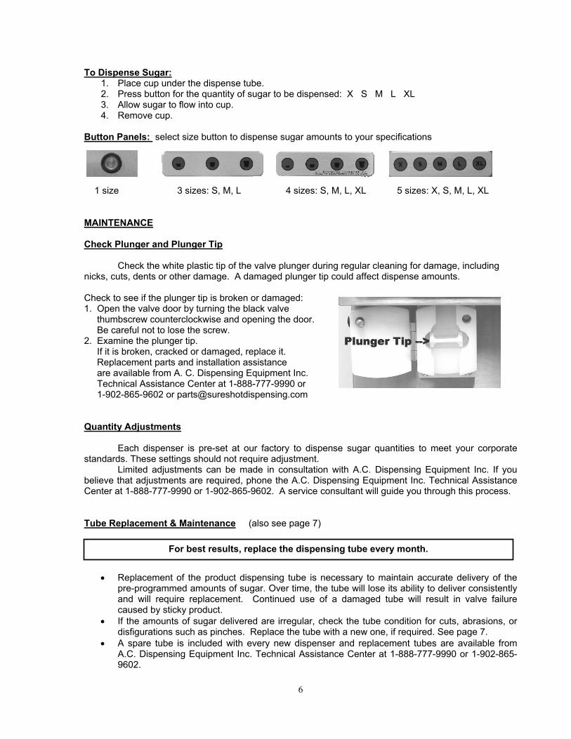
To Dispense Sugar: 1. Place cup under the dispense tube. 2. Press button for the quantity of sugar to be dispensed: X S M L XL 3. Allow sugar to flow into cup. 4. Remove cup.
Button Panels: select size button to dispense sugar amounts to your specifications
1 size 3 sizes: S, M, L 4 sizes: S, M, L, XL 5 sizes: X, S, M, L, XL MAINTENANCE Check Plunger and Plunger Tip Check the white plastic tip of the valve plunger during regular cleaning for damage, including nicks, cuts, dents or other damage. A damaged plunger tip could affect dispense amounts. Check to see if the plunger tip is broken or damaged: 1. Open the valve door by turning the black valve thumbscrew counterclockwise and opening the door. Be careful not to lose the screw. 2. Examine the plunger tip. If it is broken, cracked or damaged, replace it. Replacement parts and installation assistance are available from A. C. Dispensing Equipment Inc. Technical Assistance Center at 1-888-777-9990 or 1-902-865-9602 or [email protected] Quantity Adjustments Each dispenser is pre-set at our factory to dispense sugar quantities to meet your corporate standards. These settings should not require adjustment. Limited adjustments can be made in consultation with A.C. Dispensing Equipment Inc. If you believe that adjustments are required, phone the A.C. Dispensing Equipment Inc. Technical Assistance Center at 1-888-777-9990 or 1-902-865-9602. A service consultant will guide you through this process. Tube Replacement & Maintenance (also see page 7)
• Replacement of the product dispensing tube is necessary to maintain accurate delivery of the pre-programmed amounts of sugar. Over time, the tube will lose its ability to deliver consistently and will require replacement. Continued use of a damaged tube will result in valve failure caused by sticky product.
• If the amounts of sugar delivered are irregular, check the tube condition for cuts, abrasions, or disfigurations such as pinches. Replace the tube with a new one, if required. See page 7.
• A spare tube is included with every new dispenser and replacement tubes are available from A.C. Dispensing Equipment Inc. Technical Assistance Center at 1-888-777-9990 or 1-902-865-9602.
For best results, replace the dispensing tube every month.

7
AC6.E Sugar Dispenser – Tube Changing Procedure (All Models)
1. Place the dispenser on a level countertop. Unplug the dispenser. 2. Turn the black valve thumbscrew counterclockwise. Open the valve door. 3. Remove the black thumbscrew at the base of the hopper on the back of the dispenser. 4. Lift the hopper carefully, straight up off the dispenser base.
• Do not pull on the cord that connects the control panel to the circuit board.
5. Lay the dispenser on its side
• Do not unplug or pull on the control panel cord.
6. Examine the dispensing tube. 7. If the tube is older than 30 days or is cut or cracked, it must be replaced immediately. Remove the old dispensing tube by pulling it off the white fitment. 8. Replace with a new dispensing tube – slowly turn the tube as you push it on the white fitment. 9. Replace the hopper on the base. 10. Replace and hand-tighten the black hopper thumbscrew by turning it clockwise. 11. Ensure the dispensing tube is aligned in the center of the dispense valve. Do not kink or twist the tube. 12. Close the valve door by inserting the black valve thumbscrew and turning it clockwise. Do not over-tighten. 13. If necessary, use sharp scissors to cut off any excess tube hanging below the bottom of the dispense valve to about ¼”. 14. Reconnect to the power source. 15. Push any button and the valve will open and close. The dispenser is now ready to be loaded with sugar.
Step 2
Step 3
Step 4
Step 6
Step 7
8
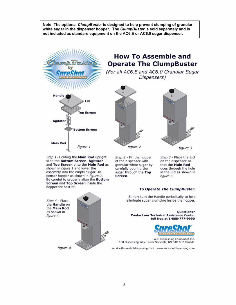
Note: The optional ClumpBuster is designed to help prevent clumping of granular white sugar in the dispenser hopper. The ClumpBuster is sold separately and is not included as standard equipment on the AC6.E or AC6.0 sugar dispenser.

9
3. CLEANING Cleaning: Catch Tray Note: The catch tray at the front and must be removed for cleaning, by lifting it up and off. 1. Rinse the tray with lukewarm potable water. 2. Place the tray in a hot water wash at a minimum water temperature of 140 ºF or 60 ºC.
• A good quality general cleaner should be added to the hot wash water at the concentrations recommended by the detergent supplier.
3. Wash thoroughly, using a bottle brush to reach all the corners and crevices. • If a dishwasher is available at the location, this step may be carried out by placing the tray in
the dishwasher and washing on the pot cycle. 4. After washing, rinse the tray well with lukewarm potable water. 5. Turn the tray upside down. Air dry. Dry thoroughly. . Cleaning: The Exterior 1. Use a soft cloth to wipe down the exterior surfaces of the dispenser to maintain the lustre of the stainless steel finish. Do not use any abrasive materials – a stainless steel cleaner is recommended. Cleaning: The Sugar Hopper 1. Unplug the dispenser from its power source. 2. Empty the product hopper: a. Remove the lid from the hopper compartment. b. If you have a dispenser model with a top screen, remove that screen and be aware that the bottom screen is still in the hopper. Do not lose the bottom screen – it is necessary for the proper operation of the dispenser and the optional Clumpbuster. c. Remove the sugar. d. Remove the bottom screen. 3. Open the valve door by removing the black valve thumbscrew. 4. Remove the black thumbscrew on the back of the hopper by turning it counterclockwise. See step 3, page 7. 7. Lift the hopper compartment (including the tube) off the dispenser. 8. Remove the product dispensing tube as shown on Page 7. 9. HOPPER: Wash the hopper compartment carefully with warm, soapy water and rinse with warm water. 10. Dry the compartment. Dry thoroughly. 11. SCREENS: Wash the screens separately using warm, soapy water and rinse with warm water. 12. Dry the screens. Dry thoroughly. 13. DISPENSE TUBE: Install a new dispensing tube. 14. Re-assemble the dispenser as shown on Page 7. When re-assembling the dispenser, ensure that the bottom screen is in place. Ensure that the dispensing tube is properly aligned in the valve. 14. Plug the dispenser back in to the power source. 15. Push any button and the valve will open and close. 16. Refill the hopper compartment with sugar. 17. Replace the lid.

10
Cleaning: The Valve Assembly 1. Unplug the dispenser. 2. Remove the sugar from the hopper, to avoid spillage when the valve door is opened. It is not necessary to remove the hopper. If you do remove the hopper, you must unplug the electrical line connecting the Button Panel to the Circuit Board. 3. Turn the black thumbscrew on the valve door counter-clockwise. 4. Open the valve door. Release the dispense tube. 5. Remove the bottom rear cover: remove the 4 Phillips screws and the central black thumbscrew securing the top hopper. 6. Disconnect the 2 solenoid wires from the Circuit Board (the 2 white wires at the left side of the Circuit Board, at positions +24 and SOL1) by turning the slot screws in the connector strip counterclockwise. 7. Remove the 4 Phillips screws at the four corners of the valve block. 8. Gently pull the valve assembly forward, with the attached wires. 9. Remove the 4 Phillips screws holding the solenoid in place. 10 Separate the solenoid from the valve. 11. Wash the plastic valve block, the plunger, plunger tip, and spring in warm, soapy water. Do not wash the solenoid. 12. Dry the valve block, plunger, plunger, tip and spring. Dry thoroughly, to prevent clumping. NOTES:
• To resume use of the dispenser, you must reassemble, making sure you follow the reverse order of steps, and then plug the dispenser in to the power source. • Make sure the 2 longer screws attaching the solenoid to the valve block are inserted first, followed by the 2 shorter screws on the face of the valve. • Make sure the plunger is aligned properly in the valve and the plunger is not binding before tightening the bracket screws • Do not use any lubricant when you reassemble the valve.

11
Cleaning: The Valve Area Over time, the dispensing valve may become sticky if sugar is deposited in the valve area because the product dispensing tube is cut or broken. A sticky valve can cause serious damage to the solenoid assembly, so it is recommended that the valve be cleaned and a new dispensing tube installed. 1. Carefully wipe the valve area with a damp cloth to remove any sticky deposits. Ensure you clean around the plunger thoroughly. Do not spray any liquid, such as a cleaner, in or around the valve area. 2. Dry the valve thoroughly and install a new dispensing tube. See Instructions, p 7.
Preventative Cleaning and Maintenance Schedule
Frequency Equipment Procedure
Daily Outside of dispenser Use damp cloth to wipe down all external stainless steel parts. Do not use abrasive cleaners. See page 9.
Daily Catch Tray See page 9.
Daily Sugar Make sure that the sugar is stored in an air-tight compartment to avoid moisture being absorbed.
Monthly Tube replacement Replace dispensing tube. See page 7.
Monthly Valve area See page 11 (above).
Monthly Sugar Hopper See page 9.
Every 3 months Valve Assemblies Remove valve assemblies, plunger and spring. Clean with warm, soapy water. See page 10.

12
4. TECHNICAL SERVICE Install Legs Dispensers are shipped with the ski-legs attached. In older model dispensers, the stainless steel bottom and the two skis are attached separately to the bottom of the dispenser. If it’s necessary to re-attach, 1. Screw in the 4 hex-screws that attach the bottom to the dispenser 2. Screw in the 2 Phillips screws that attach each ski. In newer models, the bottom and skis are one piece. If it’s necessary to re-attach, 1. Screw in the 7 Phillips screws that attach the bottom to the dispenser. NOTE:
• Do not remove the skis/legs from the dispenser or allow it to sit flat on the counter. • There are rubber feet at each end of the skis and on the bottom of the dispenser. Make sure the rubber feet are in place. If one has loosened during shipping, insert it. You may use a small screwdriver to tuck the rubber into the holes. Contact A.C. Dispensing Equipment Inc. for replacement feet at 1-888-777-9990 or 1-902-865-9602.
Remove Hopper See page 7. 1. Remove all sugar from the hopper. 2. Place the dispenser on a level countertop. Unplug the dispenser. 3. Turn the black valve thumbscrew counterclockwise. Open the valve door to release the dispense tube. 4. Remove the black thumbscrew at the base of the hopper on the back of the dispenser. 4. Lift the hopper carefully, straight up off the dispenser base.
• Do not pull on the cord that connects the control panel to the circuit board.
To re-assemble: Replace the hopper on the dispenser base. Replace and hand-tighten the black hopper thumbscrew by turning it clockwise. Ensure the dispensing tube is aligned in the center of the dispense valve. Do not kink or twist the tube. Close the valve door by inserting the black valve thumbscrew and turning it clockwise. Do not over-tighten. Reconnect to the power source. Push any button and the valve will open and close. The dispenser is now ready to be loaded with sugar.
13
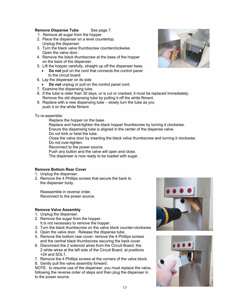
Remove Dispense Tube See page 7. 1. Remove all sugar from the hopper. 2. Place the dispenser on a level countertop. Unplug the dispenser. 3. Turn the black valve thumbscrew counterclockwise. Open the valve door. 4. Remove the black thumbscrew at the base of the hopper on the back of the dispenser. 5. Lift the hopper carefully, straight up off the dispenser base.
• Do not pull on the cord that connects the control panel to the circuit board.
6. Lay the dispenser on its side • Do not unplug or pull on the control panel cord.
7. Examine the dispensing tube. 8. If the tube is older than 30 days, or is cut or cracked, it must be replaced immediately. Remove the old dispensing tube by pulling it off the white fitment. 9. Replace with a new dispensing tube – slowly turn the tube as you push it on the white fitment. To re-assemble: Replace the hopper on the base. Replace and hand-tighten the black hopper thumbscrew by turning it clockwise. Ensure the dispensing tube is aligned in the center of the dispense valve. Do not kink or twist the tube. Close the valve door by inserting the black valve thumbscrew and turning it clockwise. Do not over-tighten. Reconnect to the power source. Push any button and the valve will open and close. The dispenser is now ready to be loaded with sugar. Remove Bottom Rear Cover 1. Unplug the dispenser. 2. Remove the 4 Phillips screws that secure the back to the dispenser body. Reassemble in reverse order. Reconnect to the power source. Remove Valve Assembly 1. Unplug the dispenser. 2. Remove the sugar from the hopper. It is not necessary to remove the hopper. 3. Turn the black thumbscrew on the valve block counter-clockwise. 4. Open the valve door. Release the dispense tube. 5. Remove the bottom rear cover: remove the 4 Phillips screws and the central black thumbscrew securing the back cover. 6. Disconnect the 2 solenoid wires from the Circuit Board, the 2 white wires at the left side of the Circuit Board, at positions +24 and SOL1. 7. Remove the 4 Phillips screws at the corners of the valve block. 8. Gently pull the valve assembly forward. NOTE: to resume use of the dispenser, you must replace the valve, following the reverse order of steps and then plug the dispenser in to the power source.

14
Remove Dispensing Solenoid Assembly
1. Unplug the dispenser. 2. Remove the sugar from the hopper, to avoid spillage when the valve door is opened. It is not necessary to remove the hopper. If you do remove the hopper, you must unplug the hopper line from the Circuit Board. 3. Turn the black thumbscrew on the valve door counter-clockwise. 4. Open the valve door. Release the dispense tube. 5. Remove the bottom rear cover: remove the 4 Phillips screws and the central black thumbscrew securing the back to the dispenser body. 6. Disconnect the 2 solenoid wires from the Circuit Board (the 2 white wires at the left side of the Circuit Board, at positions +24 and SOL1) by turning the slot screws in the connector strip counterclockwise. 7. Remove the 4 Phillips screws at the four corners of the valve block. 8. Gently pull the valve assembly forward, with the attached wires. 9. Remove the 4 Phillips screws holding the solenoid in place. 10 Separate the solenoid from the valve. Pull the aluminum insert attached to the valve forward from the back of the valve. NOTES: To resume use of the dispenser, you must reassemble, making sure you follow the reverse order of steps, and then plug the dispenser in to the power source. Make sure the 2 longer screws attaching the solenoid to the valve block are inserted first, followed by the 2 shorter screws on the face of the valve. Make sure the plunger is aligned properly in the valve and the plunger is not binding before tightening the bracket screws
15
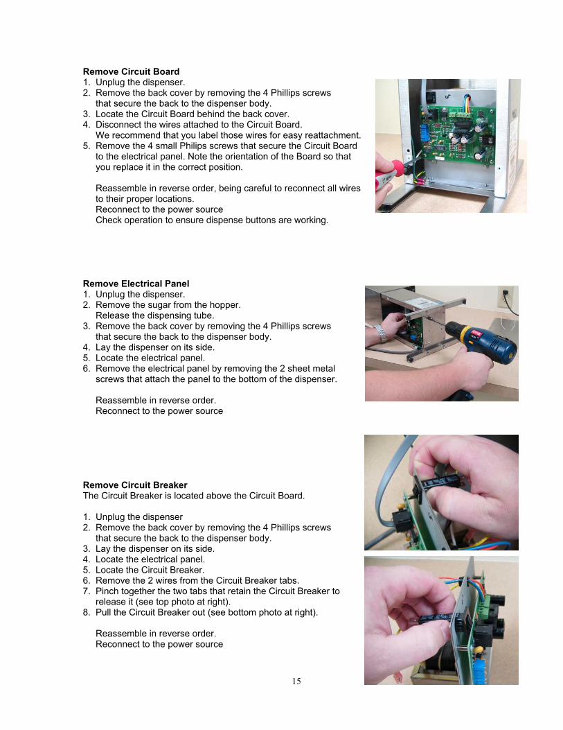
Remove Circuit Board 1. Unplug the dispenser. 2. Remove the back cover by removing the 4 Phillips screws that secure the back to the dispenser body. 3. Locate the Circuit Board behind the back cover. 4. Disconnect the wires attached to the Circuit Board. We recommend that you label those wires for easy reattachment. 5. Remove the 4 small Philips screws that secure the Circuit Board to the electrical panel. Note the orientation of the Board so that you replace it in the correct position. Reassemble in reverse order, being careful to reconnect all wires to their proper locations. Reconnect to the power source Check operation to ensure dispense buttons are working. Remove Electrical Panel 1. Unplug the dispenser. 2. Remove the sugar from the hopper. Release the dispensing tube. 3. Remove the back cover by removing the 4 Phillips screws that secure the back to the dispenser body. 4. Lay the dispenser on its side. 5. Locate the electrical panel. 6. Remove the electrical panel by removing the 2 sheet metal screws that attach the panel to the bottom of the dispenser. Reassemble in reverse order. Reconnect to the power source Remove Circuit Breaker The Circuit Breaker is located above the Circuit Board. 1. Unplug the dispenser 2. Remove the back cover by removing the 4 Phillips screws that secure the back to the dispenser body. 3. Lay the dispenser on its side. 4. Locate the electrical panel. 5. Locate the Circuit Breaker. 6. Remove the 2 wires from the Circuit Breaker tabs. 7. Pinch together the two tabs that retain the Circuit Breaker to release it (see top photo at right). 8. Pull the Circuit Breaker out (see bottom photo at right). Reassemble in reverse order. Reconnect to the power source
16
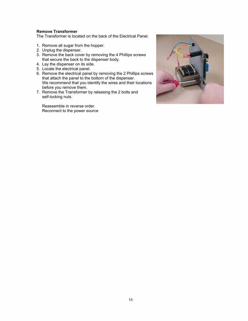
Remove Transformer The Transformer is located on the back of the Electrical Panel. 1. Remove all sugar from the hopper. 2. Unplug the dispenser. 3. Remove the back cover by removing the 4 Phillips screws that secure the back to the dispenser body. 4. Lay the dispenser on its side. 5. Locate the electrical panel. 6. Remove the electrical panel by removing the 2 Phillips screws that attach the panel to the bottom of the dispenser. We recommend that you identify the wires and their locations before you remove them. 7. Remove the Transformer by releasing the 2 bolts and self-locking nuts. Reassemble in reverse order. Reconnect to the power source

17
5. Checks and Adjustments AC Outlet for 115 VAC 1. Using a Digital Multi-Meter set to AC (~), place probes in the slotted sections of the wall outlet. The Digital Multi-Meter should read 115 ± 8 VAC. If this voltage is 0 Volts AC, this may indicate a tripped Circuit Breaker in the building’s Electrical panel. If the voltage is outside the specified range, please contact a licensed electrician to investigate. Input to Transformer AC 115 VAC input to Transformer Note: Unplug the dispenser until you are ready to check. 1. Locate the Transformer on the back of the Electrical Panel. You will see 2 wires entering the Transformer. 2. Carefully pull back the push-on connectors. 3. Plug the power back in. 4. With Digital Multi-Meter set to AC (~), place probes on the posts of the Transformer. Your meter should read 115 ± 8 VAC. 5. Replace as necessary. Output from Transformer to Circuit Board AC 24/12 VAC output to PCB from Transformer Note: Unplug the dispenser until you are ready to check. ct = center tap 1. Locate the Transformer on the back of the Electrical Panel. You will see 3 wires from the Transformer. 2. Carefully pull back the push-on connectors. 3. Plug the power back in. 4. With Digital Multi-Meter set to AC Volts (~), place the probes on the posts of the Transformer. Your meter should read: Orange (ct) ~ Yellow = 14 VAC ± 1 VAC Orange (ct) ~ Blue = 14 VAC ± 1 VAC Yellow ~ Blue = 28 VAC ± 2 VAC 4. If you do not get these voltages, check the input to the transformer and the Circuit Breaker for trip and/or continuity. NOTE: The power LED on the Circuit Board may still illuminate, even with the Circuit Breaker tripped.

18
Output from Circuit Board to Solenoid 38 VDC output to Solenoid Note: Unplug the dispenser until you are ready to check. 1. Remove the back cover – remove the 4 Phillips screws. 2. Plug the dispenser back in. 3. With the Digital Multi-Meter set to DC Volts, check for 32 ± 6 VDC between pin 1 (+24) and Pin 2 (SOL 1) on J2 terminal strip. 4. Press the Large size button. 5. If you are not getting the proper voltage at these test points, check Transformer Output, Button Panel Continuity, and then, if necessary, replace the Circuit Board. NOTE: If you are using a digital meter, the measurement may flash only momentarily on the display of the meter. Testing Button Panel Continuity Check the output from the control buttons: Check for momentary continuity by removing the telephone type jack from the circuit board and using the white wire as the common, trying the different wires as the buttons are being pushed. Remember that this electrical impulse will happen very quickly. The following are the colour codes for the wires in the jack: Wire 3, 4 Button Models 5 Button Models white common common black not used extra large red extra large large green large medium yellow medium small blue small extra small Continuity Check for Circuit Breaker Note: Turn the power off for this check. 1. Remove the valve cover – remove the 4 Phillips screws. 2. With the Digital Multi-Meter set to Continuity, check for 0 ohms reading across the 2 quick-connect tabs of the Circuit Breaker. 3. If the reading is something other than 0 ohms, the Circuit Breaker must be replaced.
19
Calibration Procedure – for dispense buttons: NOTE:
• Dispensers with Serial Numbers up to and including 5005-11617 dispense on timers located on the Circuit Board. Follow Step 5, Procedure A. See Picture, page 20.
• Dispensers with Serial Numbers 5005-11618 and above dispense on timers controlled by a microprocessor on the Circuit Board. Follow Step 5, Procedure B. See Picture, page 20.
1. Install a new dispense tube on the dispenser. 2. Fill the product hopper. Place a clean container under the dispense tube to catch sugar dispensed during calibration. 3. Run 2 cups of sugar through the dispenser by continuously dispensing the small size button to break in the new dispense tube. 4. Using either a digital scale or a measuring vial, dispense from each size button and record the measured amounts dispensed. 5. If these amounts are not correct: remove the back panel from dispenser and locate the circuit board PROCEDURE A: a locate the blue adjustment pots with slotted screw heads labelled small to x-large or x to large b insert a small slot screw driver into the head and adjust clockwise to increase the amounts or counter-clockwise to decrease the amounts PROCEDURE B: a Press the Program button. (All Binary LEDs will illuminate) b Select the Size button required to be adjusted on the button panel. (solenoid will activate, use a clean container to catch the sugar dispensed) c The Scale Led will flash the number of times corresponding to the multiplier value used in Table 1
• The Binary LEDs will indicate the binary value used to determine the portion timing when multiplied by the Scale value. E.g., 3 flashes, multiply by 10. See Table 1. d To adjust the Binary values use the UP or DOWN buttons to increment or decrement this value. e Press the size button to sample the new setting for correct portion amount. Repeat step 5 to further adjust portion amount if necessary.
• When all Binary LEDs are illuminated the program will re-scale to the next higher scale available, which will cause the binary value to be re-calculated accordingly.
• When adjusting to a lower portion timing, the program will always select the lowest scale value possible that can represent the portion timing using the allowed binary value.
g To reset portion timing to factory setting, select portion to be reset on button panel, press both the UP and DOWN buttons on the Circuit Board, then release. Table 1: Scale Multiplier Value Table 2: Binary Values Scale Scale Multiplier Value Range: 1 - 255 1 1 ms (To be multiplied by the scale value 2 5 ms to obtain portion timing in 3 10 ms milliseconds.) 4 50 ms 5 100 ms 6. Check for proper measurements after each adjustment. 7. Replace the back panel.

20
Timing Pots

21
6. Diagrams WIRING DIAGRAM – 120 VAC

22
WIRING DIAGRAM – 240 VAC
23
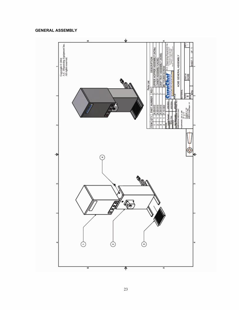
GENERAL ASSEMBLY

24
7. Parts List Part # Description A-03-012 Upper Body Assembly (A6e) No panel A-03-012-1 Upper Body Assembly – 5-button panel A-03-012-2 Upper Body Assembly – 4-button panel A-03-012-3 Upper Body Assembly – 3-button panel A-03-013 Lower Body – multibutton (Assembly AC6E) A-03-013-1 Lower Body Assembly (AC6E-single button) A-04-013 Catch Tray Assembly(AC6E) M-02-041 Catch Tray Body (AC6.E) M-02-042 Catch Tray Screen (AC6.E) A-04-014 Ski Leg Assembly – optional – for older dispensers A-03-021 ClumpBuster Assembly – regular without latch A-03-021-2 ClumpBuster Assembly – regular with latch A-03-031 ClumpBuster Assembly – oversize without latch A-03-031-2 ClumpBuster Assembly – oversize with latch F-14-024 ClumpBuster handle M-01-108 ClumpBuster lid (Top Cover – CB AC6.E) M-01-127 ClumpBuster lid (Top Cover – CB 7.25 AC6.E) A-99-035-1 ClumpBuster lid (Top Cover – CB with latch assembly) A-99-035-2 ClumpBuster lid (Top Cover – CB 7.25 with latch assembly) M-02-077A ClumpBuster top screen (Hopper Screen – Upper CB AC6.E) 6.193 x 6.217 in. M-02-078 ClumpBuster agitator (Auger – Upper CB) M-02-082A ClumpBuster bottom screen (Hopper Screen – Lower CB AC6.E) 2.497 x 2.402 in A-15-002 ClumpBuster main rod assembly M-01-061 Lid - for non-ClumpBuster dispensers A-99—035 Lid – for ClumpBuster dispenser M-02-057 Screen - Top – for non-ClumpBuster dispensers M-02-045 Screen - Bottom - for non-ClumpBuster dispensers A-10-025 1 Button Switch (Single Button Cable Assembly) E-15-011 3 Button Control Panel – G E-15-009 4 Button Control Panel – G E-15-013 5 Button Control Panel A-10-012E Ground Wire – lower A-10-012F Ground Wire - upper A-06-011-1 Electrical Panel E-22-004 Transformer A-12-014 Circuit Board – multibutton dispensers A-12-014-1 Circuit Board – PCB Assembly single button dispenser E-14-003 Circuit Breaker E-21-001 Solenoid Body A-99-036 Valve Assembly A-14-023 Valve/Solenoid Assembly A-10-013 AC Power Cord Assembly F-99-004 Rubber Feet (rubber bump insert)

25
Part # Description A-99-013 Thumbscrew (Valve Door Screw) F-10-002 #6 Thumb Screw on back of dispenser (also available as P-01-012) F-04-003 Hex screws for the electrical panel F-13-001 Plastic Retainer (grommet) at Electrical Cord entry M-05-041 natural latex sugar tube M-05-041A Tube (spare bag of 1) M-05-041B spare tube – bag of 3 unlabeled M-05-041C spare tube – bag of 3 labeled M-05-041D spare tube – bag of 9 labeled M-05-041E spare tube – bag of 6

26
8. TROUBLESHOOTING - AC6.E DISPENSERS NOTE: A. The Warranty will be null and void if the dispenser is serviced by unqualified people. B. To achieve optimum performance of your AC6.E dispenser and to avoid dispensing inconsistencies, be sure to replace the dispensing tube monthly.
PROBLEM ACTION
no power is available at the plug
1. Have a qualified person check your in-store fuse box or circuit-breaker to restore power to the circuit.
the dispenser will not dispense product
1. Make sure the power cord is plugged in and power is active. 2. Unplug the dispenser, wait 10 seconds, then plug the dispenser back in. (This resets the microprocessor.) 3. Make sure there is sugar in the hopper compartment. 4. Make sure the product dispensing tube is clear of blockage and is properly aligned in the valve with no twists or kinks. 5. Check the dispensing tube for cuts, abrasions and disfigurations and replace with a new tube if necessary. See page 7. NOTE: The dispensing tube should be replaced every month. Keep a supply of replacement tubes on hand. 6. Check the internal circuit breaker which is located inside the back panel of the dispenser. Confirm that this circuit breaker has not tripped. If it has, reset it by gently pushing it back into position. 7. Check to see if the sugar is clumping in the hopper. If it is, - consider purchasing a ClumpBuster – see page 8. - ensure that no moisture is getting into the hopper - ensure that the dispenser is thoroughly dried when cleaned - ensure that sugar supplies are stored away from moisture in a sealed container so that no clumps are added to the hopper - if sugar is clumping, empty the dispenser hopper and fill it with new sugar. 8. Check to see if the plunger tip is broken: - Open the valve door - Check plunger tip. If it is broken, cracked or damaged, replace it. See page 6. Replacement parts and installation assistance are available from A. C. Dispensing Equipment Inc. Technical Assistance Center at 1-888-777-9990 or 1-902-865-9602 or [email protected] 9. Check to see if the valve assembly is dirty or sticky. If it is, clean it. To clean, see page 10. 10. Check the transformer for input 115 VAC ± 8 VAC and output of Orange (ct) ~ Yellow = 14 VAC ± 1 VAC Orange (ct) ~ Blue = 14 VAC ± 1 VAC Yellow ~ Blue = 28 VAC ± 2 VAC See page 17. 11. Check the circuit board output for 32 ± 6 VDC between pin 1 (+24) and Pin 2 (SOL 1) on J2 terminal strip. See page 18. 12. If there's still no product dispensed, contact the A.C. Dispensing Equipment Inc. Technical Assistance Center at 1-888-777-9990 or 1-902-865-9602.
dispensing tube is worn, damaged, or cut
1. Replace the dispensing tube. See page 7.

27
the dispenser is leaking product
1. Make sure the product dispensing tube running from the hopper compartment through the delivery valve is properly aligned in the centre of the valve and the black valve thumbscrew is securely tightened (do not over-tighten). 2. Check the tube for cuts, cracks or disfiguration and replace if necessary. See page 7. 3. Check to see if the plunger tip is broken: - Open the valve door - Check plunger tip. If it is broken, cracked or damaged, replace it. See page 6. Replacement parts and installation assistance are available from A. C. Dispensing Equipment Inc. Technical Assistance Center at 1-888-777-9990 or 1-902-865-9602 or [email protected]
the valve is sticky A sticky valve is usually caused by product being deposited on the valve because the product dispensing tube is cut or broken. A sticky valve can cause serious damage to the solenoid assembly, so check the tube for cuts, abrasions and disfigurations and replace if necessary. 1. If the valve is sticky, clean the valve by carefully wiping the valve area with a damp cloth to remove any sticky deposits. Note: Do not spray any liquid, such as a cleaner, in or around the valve area. 2. Dry the valve thoroughly. 3. If this doesn't correct the problem, call the A. C. Dispensing Equipment Inc. Technical Assistance Center at 1-888-777-9990 or 1-902-865-9602.
inconsistent amounts of product are being dispensed
1. Check the hopper compartment and remove any lumps of sugar or foreign material. Replace sugar if necessary. 2. Make sure the product is of good consistency and is not damp. 3. Check the dispensing tube for cuts, abrasions and disfigurations and replace if necessary. See page 7. 4. Check to see if the plunger tip is broken: - Open the valve door - Check plunger tip. If it is broken, cracked or damaged, replace it. See page 6. Replacement parts and installation assistance are available from A. C. Dispensing Equipment Inc. Technical Assistance Center at 1-888-777-9990 or 1-902-865-9602 or [email protected] 5. Remove and clean the valve assembly. See page 10.
the dispenser does not appear to be level
1. Check to make sure all four rubber feet at the bottom corners of the dispenser are in place. Replacement feet are available from A.C. Dispensing Equipment Inc. Technical Assistance Center at 1-888-777- 9990 or 1-902-865-9602.
dispenser is dispensing sugar on its own
1. Make sure the Circuit Board is not loose. 2. Make sure that a grounding wire is attached from the top hopper to the frame of the dispenser. If the dispenser has no grounding wire, add one: from the grounding stud on the base plate to one of the 4 sheet metal screws on the underside of the hopper. The grounding wire is a 22” 18 AWG wire with ring connectors on both ends.
If the instructions above do not correct your problem, please contact A. C. Dispensing Equipment Inc. Technical Assistance Center at 1-888-777-9990 or 1-902-865-9602.
NORTH AMERICAN WARRANTY All dispensing equipment manufactured by A.C. Dispensing Equipment Inc. is warranted against defects in materials and workmanship for a period of one (1) year from the date of purchase. A. C. Dispensing Equipment Inc.'s obligation under this warranty is limited to the repair of defects as outlined by an A. C. Dispensing Equipment Inc. factory-authorized service agency or one of its sub-service agencies. This Warranty does not apply to installation or problems because of installation. This Warranty does not apply to normal preventative maintenance, maintenance or adjustment. THIS WARRANTY WILL BE NULL AND VOID IF THE WARRANTY REGISTRATION CARD IS NOT RETURNED TO A. C. DISPENSING EQUIPMENT INC. WITHIN 60 DAYS OF PURCHASE. This warranty is subject to the following conditions: • This warranty applies to the original owner only and is not assignable. • Only pre-authorized service agencies directed by A.C. Dispensing Equipment Inc. are to be utilized. • Should any product fail to function in its intended manner under normal use within the limits defined in this warranty, at the option of A. C. Dispensing Equipment Inc. such product will be repaired or replaced by A.C. Dispensing Equipment Inc. or its Authorized Service Agency. A. C. Dispensing Equipment Inc. will be responsible only for charges incurred or service performed by its Authorized Service Agencies. The use of other than A. C. Dispensing Equipment Inc. Authorized Service Agencies will void this warranty and A. C. Dispensing Equipment Inc. will not be responsible for such work or any charges associated with such work. The closest A. C. Dispensing Equipment Inc. Authorized Service Agency must be used and must be dispatched by A. C. Dispensing Equipment Inc. TIME PERIOD: One year on parts and labour, effective from the date of purchase. The Authorized Service Agency may, at its option, require proof of purchase. Parts replaced under this Warranty are warranted for the unexpired portion of the original product warranty only.
24-hour Toll-Free Service is available at 1-888-777-9990 or 1-902-865-9602 A service consultant is available to assist you during our normal business hours. All service-related issues will be addressed by a return telephone call the next business day. WARRANTY PROCEDURE: 1. Secure the model and serial number from the data tag on the lower left side of the dispenser. 2. Call the number provided on the service label on the dispenser. 3. Our technical support staff will discuss the issue with you and, if necessary, dispatch a technician to your location for repairs. If after-hours or emergency service is required, A.C. Dispensing Equipment Inc. will not be responsible for any additional charges. 4. To order parts, call the service center and the appropriate parts will be sent to your location or that of the servicing agency.
The following conditions are not covered by this Warranty: • Equipment failure related to improper installation, improper utility connection or supply, and problems due to ventilation. • Equipment that has not been properly maintained (including the changing of the product delivery tube monthly), calibration of controls, adjustments, damage from improper cleaning, and water damage to controls. • Equipment that has not been used in an appropriate manner, or has been subject to misuse or misapplication, neglect, abuse, accident, alteration, negligence, damage during transit, delivery or installation, fire, flood, riot, or act of God. • Equipment on which the model number or serial number has been removed or altered.
If the equipment has been changed, altered, modified or repaired by other than a qualified service technician during or
after the warranty period, then the manufacturer shall not be liable for any damages to any person or to any property, which may result from the use of the equipment thereafter.
This Warranty does not cover services performed at overtime or premium labour rates. Should service be required at times which normally involve overtime or premium labour rates, the owner shall be charged for the difference between normal service rates and such premium rates. A. C. Dispensing Equipment Inc. does not assume any liability for extended delays in replacing or repairing any items beyond its control.
In all cases, the use of other than A. C. Dispensing Equipment Inc. authorized OEM replacement parts will void this Warranty.
This equipment in intended for commercial use only. Warranty is void if equipment is installed in other than commercial applications.
THE FOREGOING WARRANTY IS IN LIEU OF ANY AND ALL OTHER WARRANTIES EXPRESSED OR IMPLIED, INCLUDING ANY IMPLIED WARRANTY OF MERCHANTABILITY OR FITNESS AND CONSTITUTES THE ENTIRE LIABILITY OF A. C. DISPENSING EQUIPMENT INC. IN NO EVENT DOES THE LIMITED WARRANTY EXTEND BEYOND THE TERMS STATED HEREIN.
A.C. Dispensing Equipment Inc. 100 Dispensing Way
Lower Sackville Nova Scotia, Canada
Printed: 16/12/2005 B4C 4H2