DR5688 HELDEN LDD 13PA4 V1 - 主頁 ... · PDF fileHelden has worked with clients, consultants...
13
Diameter Bespoke Fittings to Suit Any Pipe Specification Large PIPE CONNECTIONS, REPAIR & FLOW CONTROL PRODUCTS FOR THE UTILITIES INDUSTRY
Transcript of DR5688 HELDEN LDD 13PA4 V1 - 主頁 ... · PDF fileHelden has worked with clients, consultants...

DiameterB
espoke
Fittings to Suit Any Pipe Specifi cation
Large
PIPE CONNECTIONS, REPAIR & FLOW CONTROL PRODUCTS FOR THE UTILITIES INDUSTRY
Overview
Large Diameter
Pipe Materials
3 Helden Large Diameter Telephone: +44 (0)1462 443322
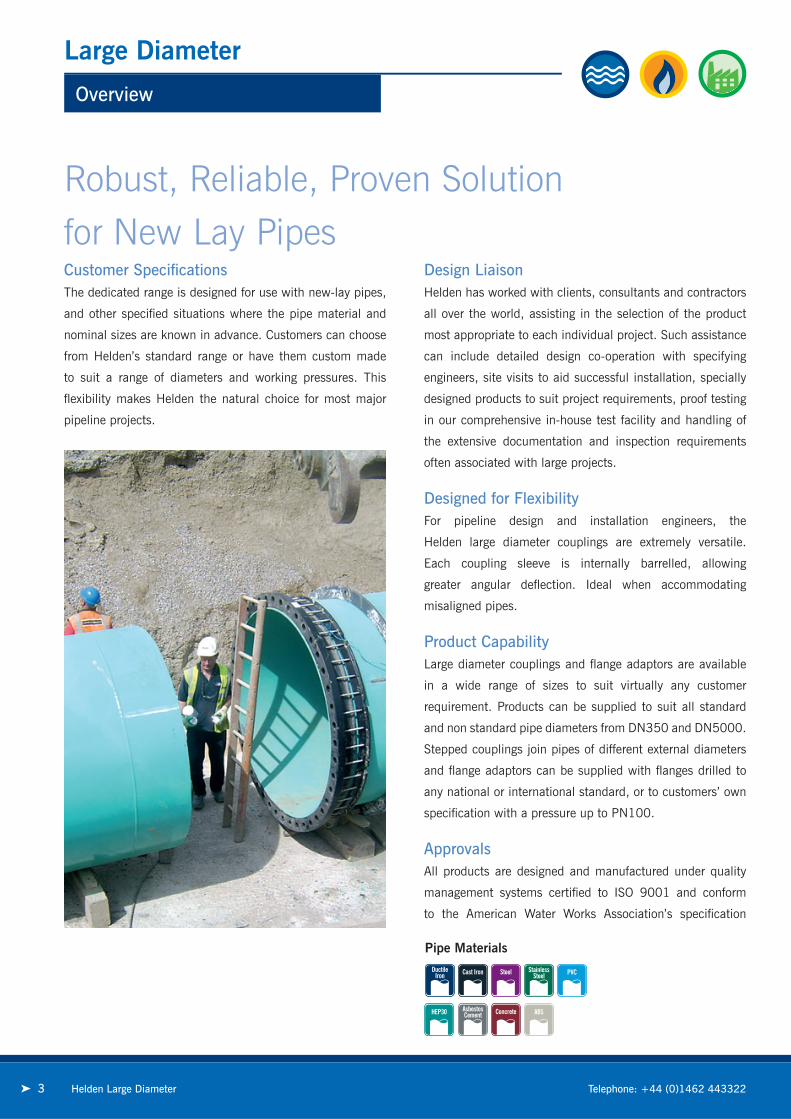
Customer Specifi cationsThe dedicated range is designed for use with new-lay pipes,
and other specifi ed situations where the pipe material and
nominal sizes are known in advance. Customers can choose
from Helden’s standard range or have them custom made
to suit a range of diameters and working pressures. This
fl exibility makes Helden the natural choice for most major
pipeline projects.
Design LiaisonHelden has worked with clients, consultants and contractors
all over the world, assisting in the selection of the product
most appropriate to each individual project. Such assistance
can include detailed design co-operation with specifying
engineers, site visits to aid successful installation, specially
designed products to suit project requirements, proof testing
in our comprehensive in-house test facility and handling of
the extensive documentation and inspection requirements
often associated with large projects.
Designed for FlexibilityFor pipeline design and installation engineers, the
Helden large diameter couplings are extremely versatile.
Each coupling sleeve is internally barrelled, allowing
greater angular defl ection. Ideal when accommodating
misaligned pipes.
Product CapabilityLarge diameter couplings and fl ange adaptors are available
in a wide range of sizes to suit virtually any customer
requirement. Products can be supplied to suit all standard
and non standard pipe diameters from DN350 and DN5000.
Stepped couplings join pipes of different external diameters
and fl ange adaptors can be supplied with fl anges drilled to
any national or international standard, or to customers’ own
specifi cation with a pressure up to PN100.
ApprovalsAll products are designed and manufactured under quality
management systems certifi ed to ISO 9001 and conform
to the American Water Works Association’s specifi cation
Robust, Reliable, Proven Solution for New Lay Pipes

Product Design Benefits
Large Diameter Couplings & Flange Adaptors
Corrosion Protection
Metal components are coated with Rilsan Nylon 11 which
is WRAS approved for use with potable water. The nuts and
bolts are Sheraplex coated to WIS 4-52-03, offering long term
protection to corrosion, impact and abrasion and therefore
ensures continued reliable performance.
Long Life Expectancy
Elastomeric sealing gaskets are designed to have at least
a 50 year lifespan.
Simple to Fit
Simple installation in any weather and trench conditions,
even underwater!
4Helden Large Diameter
Couplings can absorb up to 10mm expansion and contraction,
fl ange adaptors up to 5mm which allows for movement on
bridge crossings, in chambers and pump stations. Often
eliminates the need for special expansion joints.
Couplings can offer up to 6° of angular defl ection, fl ange
adaptors 3° - to allow for the connection of misaligned pipes;
take up ground settlement at structures; lay pipes to large
radius bends.
➤
➤
Flange adaptors are often
used to permit dismantling
of valves in fl anged
pipe systems.
The standard fi nish for all Helden products is black Rilsan
Nylon 11, which is highly resistant to impact, corrosion,
abrasion and chemical attack. However, other coatings such
as shopcoat, hot dip galvanising, zinc spray and epoxy coating
can be supplied as required.
➤
➤
Customer Benefi ts
www.helden-web.com
Mechanical C
ouplings & Flange A
daptorsD
edicated
Specifications
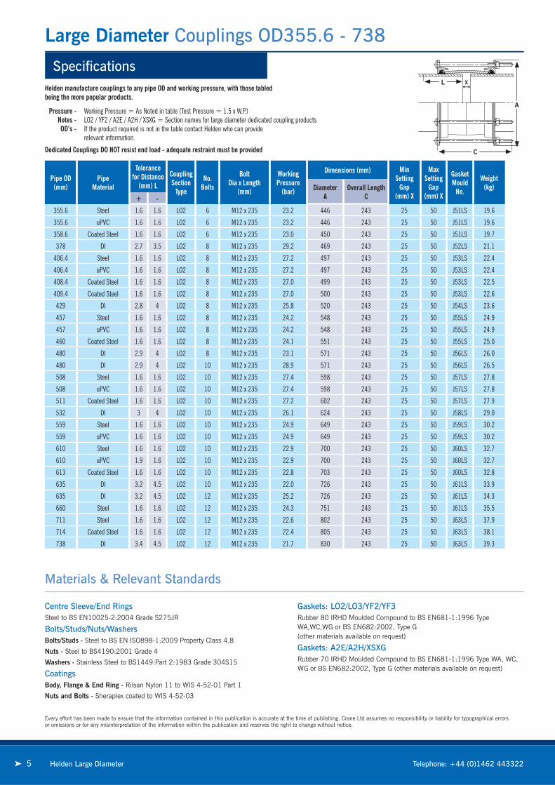
Large Diameter Couplings OD355.6 - 738
5 Helden Large Diameter Telephone: +44 (0)1462 443322
Every effort has been made to ensure that the information contained in this publication is accurate at the time of publishing. Crane Ltd assumes no responsibility or liability for typographical errorsor omissions or for any misinterpretation of the information within the publication and reserves the right to change without notice.
Centre Sleeve/End RingsSteel to BS EN10025-2:2004 Grade S275JR
Bolts/Studs/Nuts/WashersBolts/Studs - Steel to BS EN ISO898-1:2009 Property Class 4.8
Nuts - Steel to BS4190:2001 Grade 4
Washers - Stainless Steel to BS1449:Part 2:1983 Grade 304S15
CoatingsBody, Flange & End Ring - Rilsan Nylon 11 to WIS 4-52-01 Part 1
Nuts and Bolts - Sheraplex coated to WIS 4-52-03
Gaskets: LO2/LO3/YF2/YF3Rubber 80 IRHD Moulded Compound to BS EN681-1:1996 Type WA,WC,WG or BS EN682:2002, Type G (other materials available on request)
Gaskets: A2E/A2H/XSXGRubber 70 IRHD Moulded Compound to BS EN681-1:1996 Type WA, WC, WG or BS EN682:2002, Type G (other materials available on request)
Materials & Relevant Standards
A
C
L X
Pipe OD(mm)
PipeMaterial
Tolerancefor Distance
(mm) L
CouplingSection
Type
No.Bolts
Bolt Dia x Length
(mm)
WorkingPressure
(bar)
Dimensions (mm) Min Setting
Gap (mm) X
Max Setting
Gap (mm) X
Gasket Mould
No.
Weight(kg)Diameter
AOverall Length
C+ -
355.6 Steel 1.6 1.6 LO2 6 M12 x 235 23.2 446 243 25 50 J51LS 19.6
355.6 uPVC 1.6 1.6 LO2 6 M12 x 235 23.2 446 243 25 50 J51LS 19.6
358.6 Coated Steel 1.6 1.6 LO2 6 M12 x 235 23.0 450 243 25 50 J51LS 19.7
378 DI 2.7 3.5 LO2 8 M12 x 235 29.2 469 243 25 50 J52LS 21.1
406.4 Steel 1.6 1.6 LO2 8 M12 x 235 27.2 497 243 25 50 J53LS 22.4
406.4 uPVC 1.6 1.6 LO2 8 M12 x 235 27.2 497 243 25 50 J53LS 22.4
408.4 Coated Steel 1.6 1.6 LO2 8 M12 x 235 27.0 499 243 25 50 J53LS 22.5
409.4 Coated Steel 1.6 1.6 LO2 8 M12 x 235 27.0 500 243 25 50 J53LS 22.6
429 DI 2.8 4 LO2 8 M12 x 235 25.8 520 243 25 50 J54LS 23.6
457 Steel 1.6 1.6 LO2 8 M12 x 235 24.2 548 243 25 50 J55LS 24.9
457 uPVC 1.6 1.6 LO2 8 M12 x 235 24.2 548 243 25 50 J55LS 24.9
460 Coated Steel 1.6 1.6 LO2 8 M12 x 235 24.1 551 243 25 50 J55LS 25.0
480 DI 2.9 4 LO2 8 M12 x 235 23.1 571 243 25 50 J56LS 26.0
480 DI 2.9 4 LO2 10 M12 x 235 28.9 571 243 25 50 J56LS 26.5
508 Steel 1.6 1.6 LO2 10 M12 x 235 27.4 598 243 25 50 J57LS 27.8
508 uPVC 1.6 1.6 LO2 10 M12 x 235 27.4 598 243 25 50 J57LS 27.8
511 Coated Steel 1.6 1.6 LO2 10 M12 x 235 27.2 602 243 25 50 J57LS 27.9
532 DI 3 4 LO2 10 M12 x 235 26.1 624 243 25 50 J58LS 29.0
559 Steel 1.6 1.6 LO2 10 M12 x 235 24.9 649 243 25 50 J59LS 30.2
559 uPVC 1.6 1.6 LO2 10 M12 x 235 24.9 649 243 25 50 J59LS 30.2
610 Steel 1.6 1.6 LO2 10 M12 x 235 22.9 700 243 25 50 J60LS 32.7
610 uPVC 1.9 1.6 LO2 10 M12 x 235 22.9 700 243 25 50 J60LS 32.7
613 Coated Steel 1.6 1.6 LO2 10 M12 x 235 22.8 703 243 25 50 J60LS 32.8
635 DI 3.2 4.5 LO2 10 M12 x 235 22.0 726 243 25 50 J61LS 33.9
635 DI 3.2 4.5 LO2 12 M12 x 235 25.2 726 243 25 50 J61LS 34.3
660 Steel 1.6 1.6 LO2 12 M12 x 235 24.3 751 243 25 50 J61LS 35.5
711 Steel 1.6 1.6 LO2 12 M12 x 235 22.6 802 243 25 50 J63LS 37.9
714 Coated Steel 1.6 1.6 LO2 12 M12 x 235 22.4 805 243 25 50 J63LS 38.1
738 DI 3.4 4.5 LO2 12 M12 x 235 21.7 830 243 25 50 J63LS 39.3
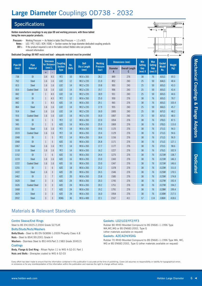
Helden manufacture couplings to any pipe OD and working pressure, with those tabled being the more popular products.
Pressure - Working Pressure = As Noted in table (Test Pressure = 1.5 x W.P.) Notes - LO2 / YF2 / A2E / A2H / XSXG = Section names for large diameter dedicated coupling products OD’s - If the product required is not in the table contact Helden who can provide relevant information.
Dedicated Couplings DO NOT resist end load - adequate restraint must be provided
Specifications
Large Diameter Couplings OD738 - 2032
6Helden Large Diameterwww.helden-web.com
Every effort has been made to ensure that the information contained in this publication is accurate at the time of publishing. Crane Ltd assumes no responsibility or liability for typographical errorsor omissions or for any misinterpretation of the information within the publication and reserves the right to change without notice.
Centre Sleeve/End RingsSteel to BS EN10025-2:2004 Grade S275JR
Bolts/Studs/Nuts/WashersBolts/Studs - Steel to BS EN ISO898-1:2009 Property Class 4.8
Nuts - Steel to BS4190:2001 Grade 4
Washers - Stainless Steel to BS1449:Part 2:1983 Grade 304S15
CoatingsBody, Flange & End Ring - Rilsan Nylon 11 to WIS 4-52-01 Part 1
Nuts and Bolts - Sheraplex coated to WIS 4-52-03
Gaskets: LO2/LO3/YF2/YF3Rubber 80 IRHD Moulded Compound to BS EN681-1:1996 Type WA,WC,WG or BS EN682:2002, Type G (other materials available on request)
Gaskets: A2E/A2H/XSXGRubber 70 IRHD Moulded Compound to BS EN681-1:1996 Type WA, WC, WG or BS EN682:2002, Type G (other materials available on request)
Materials & Relevant Standards
A
C
L X
Pipe OD(mm)
PipeMaterial
Tolerancefor Distance
(mm) L
CouplingSection
Type
No.Bolts
Bolt Dia x Length
(mm)
WorkingPressure
(bar)
Dimensions (mm) Min Setting
Gap (mm) X
Max Setting
Gap (mm) X
Gasket Mould
No.
Weight(kg)Diameter
AOverall Length
C+ -
738 DI 3.4 4.5 YF2 10 M16 x 265 28.2 849 276 38 76 J63LS 69.3
762 Steel 1.6 1.6 LO2 12 M12 x 235 21.0 852 243 25 50 J64LS 40.4
813 Steel 1.6 1.6 LO2 14 M12 x 235 19.8 903 243 25 50 J65LS 43.3
816 Coated Steel 1.6 1.6 LO2 14 M12 x 235 19.7 906 243 25 50 J65LS 43.4
842 DI 1 4.5 LO2 14 M12 x 235 18.9 931 243 25 50 J65LS 44.6
842 DI 1 4.5 YF2 12 M16 x 265 25.0 950 276 38 76 J65LS 78.7
842 DI 1 4.5 A2E 14 M16 x 265 29.1 965 276 38 76 J65LS 103.4
864 Steel 1.6 1.6 LO2 14 M12 x 235 17.9 955 243 25 50 J66LS 45.7
914 Steel 1.6 1.6 LO2 14 M12 x 235 16.0 1005 243 25 50 J67LS 48.2
916 Coated Steel 1.6 1.6 LO2 14 M12 x 235 16.0 1007 243 25 50 J67LS 48.3
945 DI 1 5 YF2 12 M16 x 265 22.0 1054 276 38 76 J70LS 87.5
945 DI 1 5 A2E 14 M16 x 265 25.9 1069 276 38 76 J70LS 115.0
1016 Steel 1.6 1.6 YF2 14 M16 x 265 19.6 1125 276 38 76 J71LS 94.3
1019 Coated Steel 1.6 1.6 YF2 14 M16 x 265 19.4 1129 276 38 76 J71LS 94.6
1048 DI 1 5 YF2 14 M16 x 265 18.4 1156 276 38 76 J71LS 96.9
1048 DI 1 5 A2E 16 M16 x 265 26.8 1171 276 38 76 J71LS 127.1
1067 Steel 1.6 1.6 YF2 14 M16 x 265 17.7 1177 276 38 76 J72LS 98.6
1118 Steel 1.6 1.6 YF2 14 M16 x 265 16.2 1227 276 38 76 J73LS 102.9
1152 DI 1 6 A2E 16 M16 x 265 24.4 1275 276 38 76 J121M 138.7
1219 Steel 1.6 1.6 A2E 16 M16 x 265 23.0 1343 276 38 76 J121M 146.3
1222 Coated Steel 1.6 1.6 A2E 16 M16 x 265 23.0 1347 276 38 76 J121M 146.6
1255 DI 1 6 A2E 18 M16 x 265 25.2 1378 276 38 76 J122M 151.0
1422 Steel 1.6 3 A2E 20 M16 x 265 24.5 1546 276 38 76 J125M 170.5
1462 DI 1 7 A2E 20 M16 x 265 23.8 1585 276 38 76 J125M 174.8
1620 Steel 3 3 A2E 24 M16 x 265 20.3 1745 276 38 76 J127M 192.4
1626 Coated Steel 3 3 A2E 24 M16 x 265 20.2 1751 276 38 76 J127M 194.2
1668 DI 1 7 A2E 24 M16 x 265 19.2 1791 276 38 76 J128M 199.4
1829 Steel 3 3 A2E 24 M16 x 265 16.0 1954 276 38 76 J130M 217.5
2032 Steel 3 3 XSXG 36 M16 x 400 22.1 2167 411 57 114 J186H 418.6
Helden manufacture couplings to any pipe OD and working pressure, with those tabled being the more popular products.
Pressure - Working Pressure = As Noted in table (Test Pressure = 1.5 x W.P.) Notes - LO2 / YF2 / A2E / A2H / XSXG = Section names for large diameter dedicated coupling products OD’s - If the product required is not in the table contact Helden who can provide relevant information.
Dedicated Couplings DO NOT resist end load - adequate restraint must be provided
Mechanical C
ouplings & Flange A
daptorsD
edicated

Specifications
Large Diameter Stepped Couplings OD355.6 - 1220
7 Helden Large Diameter Telephone: +44 (0)1462 443322
L X
A1
L X
A
C
Expanded Sleeve Stepped Couplings Stepped Coupling With Make Up Ring
A1
C
A
Centre Sleeve/End RingsSteel to BS EN10025-2:2004 Grade S275JR
Bolts/Studs/Nuts/WashersBolts/Studs - Steel to BS EN ISO898-1:2009 Property Class 4.8
Nuts - Steel to BS4190:2001 Grade 4
Washers - Stainless Steel to BS1449:Part 2:1983 Grade 304S15
CoatingsBody, Flange & End Ring - Rilsan Nylon 11 to WIS 4-52-01 Part 1
Nuts and Bolts - Sheraplex coated to WIS 4-52-03
Gaskets: LO2/LO3/YF2/YF3Rubber 80 IRHD Moulded Compound to BS EN681-1:1996 Type WA,WC,WG or BS EN682:2002, Type G (other materials available on request)
Gaskets: A2E/A2H/XSXGRubber 70 IRHD Moulded Compound to BS EN681-1:1996 Type WA, WC, WG or BS EN682:2002, Type G
(other materials available on request)
Every effort has been made to ensure that the information contained in this publication is accurate at the time of publishing. Crane Ltd assumes no responsibility or liability for typographical errorsor omissions or for any misinterpretation of the information within the publication and reserves the right to change without notice.
Materials & Relevant Standards
If the product required is not in the table contact Helden who can provide relevant information
Pressure - Working Pressure = As Noted in table (Test Pressure = 1.5 x W.P.) Notes - LO2 / YF2 / A2E / A2H / XSXG = Section names for large diameter dedicated stepped coupling products OD’s - If the product required is not in the table contact Helden who can provide relevant information.
Dedicated Couplings DO NOT resist end load - adequate restraint must be provided
Pipe
Pipe OD(mm)
Material1
Tolerancefor Distance
(mm) LMaterial
2
Tolerancefor Distance
(mm) LCoupling
Section TypeNo.
Bolts
Bolt Dia x Length
(mm)
WorkingPressure
(bar)
Dimensions (mm) Min Setting
Gap(mm)
X
Max Setting
Gap(mm)
X
Gasket Mould
No.
Weight(kg)Diameter
ADiameter
A1
Overall Length
C+ - + -
355.6 378 Steel 1.6 1.6 DI 2.7 3.5 LO2 8 M12 x 235 29.2 446 469 243 25 50 J51LS / J52LS 20.7
406.4 429 Steel 1.6 1.6 DI 2.8 4 LO2 8 M12 x 235 25.7 497 520 243 25 50 J53LS / J54LS 23.1
457 480 Steel 1.6 1.6 DI 2.9 4 LO2 8 M12 x 235 23.1 548 571 243 25 50 J55LS / J56LS 25.6
480 508 DI 2.9 4 Steel 1.6 1.6 LO2 10 M12 x 235 27.3 571 598 243 25 50 J56LS / J57LS 27.3
508 532 Steel 1.6 1.6 DI 3 4 LO2 10 M12 x 235 26.1 598 624 243 25 50 J57LS / J58LS 28.6
610 635 Steel 1.6 1.6 DI 3.2 4.5 LO2 10 M12 x 235 22.0 700 726 243 25 50 J60LS / J61LS 33.6
711 738 Steel 1.6 1.6 DI 3.4 4.5 LO2 12 M12 x 235 21.7 802 830 243 25 50 J63LS / J63LS 39.0
738 747 DI 3.4 4.5 Cast IronCD 3.3 3.3 LO2 12 M12 x 235 21.3 830 839 243 25 50 J63LS / J63LS 39.4
738 755 DI 3.4 4.5 Cast IronAB 3.3 3.3 LO2 12 M12 x 235 21.2 830 847 243 25 50 J63LS / J65LS 39.9
813 842 Steel 1.6 1.6 DI 1 4.5 LO2 14 M12 x 235 18.8 903 931 243 25 50 J65LS / J65LS 44.4
826 842 Cast IronCD 3.3 3.3 DI 1 4.5 LO2 14 M12 x 235 18.8 918 931 243 25 50 J65LS / J65LS 44.3
842 886 DI 1 4.5 Cast IronAB 3.3 3.3 LO3
(LONG SLEEVE) 14 M12 x 340 17.0 931 978 348 25 150 J65LS / J66LS 62.7
906 945 Cast IronCD 3.3 3.3 DI 1 5 YF2 12 M16 x 265 22.0 1017 1054 276 38 76 J67LS / J70LS 86.5
914 945 Steel 1.6 1.6 DI 1 5 YF2 12 M16 x 265 22.0 1024 1054 276 38 76 J67LS / J70LS 86.5
945 964 DI 1 5 Cast IronAB 3.3 3.3 YF2 12 M16 x 265 21.6 1054 1075 276 38 76 J70LS / J70LS 88.3
1016 1048 Steel 1.6 1.6 DI 1 5 YF2 14 M16 x 265 18.3 1125 1156 276 38 76 J71LS / J71LS 95.9
1121 1152 Cast IronAB 3.3 3.3 DI 1 6 A2E 16 M16 x 265 24.3 1247 1275 276 38 76 J120M / J121M 137.6
1220 1255 Steel 1.6 1.6 DI 1 6 A2E 18 M16 x 265 25.2 1344 1378 276 38 76 J120M / J132M 150.1

ProjectThe Desalination Plant will have a
capacity of up to 100 gigalitres and
will provide Adelaide with up to half
its annual water requirement. The
huge size of the plant will be powered
by sustainable energy sources and
will ensure that the majority of the
water supply is sourced from the sea
with lesser reliance placed on the
River Murray basin.
ClientSouth Australian Water
& South Australian Government
ContractorMcConnell Dowell
DistributorPhilmac
Australia - Adelaide
Desalination Plant Transfer PipelineLarge Diameter Flange Adaptor - DN1600
8Helden Large Diameterwww.helden-web.com
Mechanical C
ouplings & Flange A
daptorsD
edicated

Specifications
Large Diameter Flange Adaptors OD355.6 - 457
9 Helden Large Diameter Telephone: +44 (0)1462 443322
Pipe OD(mm)
PipeMaterial
Tolerancefor Distance
(mm) L
FASection
Type
Flange Details BS EN 1092-1
Number ofNotches
in End Ringif Required
No.Bolts
Bolt Dia x Length
(mm)
Dimensions Diameter(mm) A
FlangeODA1
Overall Length
C
Flange Thickness
T
FlangeHolesNo.
Flange Holes
Diameter(mm)
Min Setting
Gap (mm) X
Max Setting
Gap (mm) X
Gasket Mould
No.
Weight(kg)
Nominal Drilling+ -355.6 Steel 1.6 1.6 LO2 350 PN10 4 8 M12 x 140 446 505 148 18 16 23 25 50 J51LS 22.8355.6 uPVC 1.6 1.6 LO2 350 PN10 4 8 M12 x 140 446 505 148 18 16 23 25 50 J51LS 22.8355.6 Steel 1.6 1.6 LO2 350 PN16 4 8 M12 x 140 446 520 148 18 16 28 25 50 J51LS 24.1355.6 uPVC 1.6 1.6 LO2 350 PN16 4 8 M12 x 140 446 520 148 18 16 28 25 50 J51LS 24.1355.6 Steel 1.6 1.6 LO2 350 PN25 - 8 M12 x 140 446 555 155 25 16 34 25 50 J51LS 34.4358.6 Coated Steel 1.6 1.6 LO2 350 PN16 4 8 M12 x 140 450 520 148 18 16 28 25 50 J51LS 23.9378 DI 2.7 3.5 LO2 350 PN10 8 8 M12 x 140 469 505 148 18 16 23 25 50 J52LS 21.3378 DI 2.7 3.5 LO2 350 PN16 8 8 M12 x 140 469 520 148 18 16 28 25 50 J52LS 22.5378 DI 2.7 3.5 LO2 350 PN25 8 8 M12 x 140 469 555 155 25 16 34 25 50 J52LS 32.2
406.4 Steel 1.6 1.6 LO2 400 PN10 4 8 M12 x 140 497 565 148 18 16 28 25 50 J53LS 26.3406.4 uPVC 1.6 1.6 LO2 400 PN10 4 8 M12 x 140 497 565 148 18 16 28 25 50 J53LS 26.3406.4 Steel 1.6 1.6 LO2 400 PN16 4 8 M12 x 140 497 580 148 18 16 31 25 50 J53LS 27.9406.4 uPVC 1.6 1.6 LO2 400 PN16 4 8 M12 x 140 497 580 148 18 16 31 25 50 J53LS 27.9406.4 Steel 1.6 1.6 LO2 400 PN25 - 8 M12 x 140 497 620 155 25 16 37 25 50 J53LS 40.7409.4 Coated Steel 1.6 1.6 LO2 400 PN16 4 8 M12 x 140 500 580 148 18 16 31 25 50 J53LS 27.7429 DI 2.8 4 LO2 400 PN10 8 8 M12 x 140 520 565 148 18 16 28 25 50 J54LS 24.5429 DI 2.8 4 LO2 400 PN16 8 8 M12 x 140 520 580 148 18 16 31 25 50 J54LS 26.2429 DI 2.8 4 LO2 400 PN25 8 8 M12 x 140 520 620 155 25 16 37 25 50 J54LS 38.2451 PVC 1.6 1.6 LO2 450 PN16 - 10 M12 x 140 541 640 155 25 20 31 25 50 J55LS 45.2451 Hep30 0 1 LO2 450 PN16 - 10 M12 x 140 541 640 155 25 20 31 25 50 J55LS 45.2457 Steel 1.6 1.6 LO2 450 PN10 5 10 M12 x 140 548 615 153 23 20 28 25 50 J55LS 33.5457 uPVC 1.6 1.6 LO2 450 PN10 5 10 M12 x 140 548 615 153 23 20 28 25 50 J55LS 33.5457 Steel 1.6 1.6 LO2 450 PN16 - 10 M12 x 140 548 640 153 23 20 31 25 50 J55LS 37.5457 uPVC 1.6 1.6 LO2 450 PN16 - 10 M12 x 140 548 640 153 23 20 31 25 50 J55LS 37.5457 Steel 1.6 1.6 LO2 450 PN25 - 10 M12 x 140 548 670 155 25 20 37 25 50 J55LS 44.4
A
X
C
A1
T
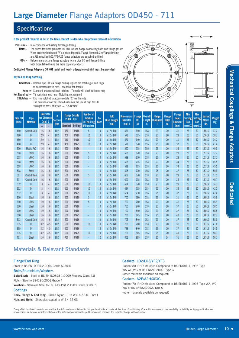
If the product required is not in the table contact Helden who can provide relevant information
Pressure - In accordance with rating for fl ange drilling Notes - The prices for these products DO NOT include fl ange connecting bolts and fl ange gasket. When ordering Dedicated FA’s, ensure Pipe O.D./Flange Nominal Size/Flange Drilling are ALL specifi ed LO2/YF2/A2E fl ange adaptors are supplied unfi tted OD’s - Helden manufacture fl ange adaptors to any pipe OD and fl ange drilling, with those tabled being the more popular products.
Dedicated Flange Adaptors DO NOT resist end load - adequate restraint must be provided
Key to End Ring Notching
Tied Rods - Certain pipe OD’s & fl ange drilling require the notching of end rings to accommodate tie rods - see table for details None = Standard product without notches - Tie rods will clash with end ring Not Required = Tie rods clear end ring - Notching not required X Notches = End ring notched to accommodate “X” no. tie rods The number of notches stated assumes the use of high tensile strength tie rods. Min yield = 725 N/mm2
Flange/End RingSteel to BS EN10025-2:2004 Grade S275JR
Bolts/Studs/Nuts/WashersBolts/Studs - Steel to BS EN ISO898-1:2009 Property Class 4.8
Nuts - Steel to BS4190:2001 Grade 4
Washers - Stainless Steel to BS1449:Part 2:1983 Grade 304S15
CoatingsBody, Flange & End Ring - Rilsan Nylon 11 to WIS 4-52-01 Part 1
Nuts and Bolts - Sheraplex coated to WIS 4-52-03
Gaskets: LO2/LO3/YF2/YF3Rubber 80 IRHD Moulded Compound to BS EN681-1:1996 Type WA,WC,WG or BS EN682:2002, Type G (other materials available on request)
Gaskets: A2E/A2H/XSXGRubber 70 IRHD Moulded Compound to BS EN681-1:1996 Type WA, WC, WG or BS EN682:2002, Type G
(other materials available on request)
Every effort has been made to ensure that the information contained in this publication is accurate at the time of publishing. Crane Ltd assumes no responsibility or liability for typographical errorsor omissions or for any misinterpretation of the information within the publication and reserves the right to change without notice.
Materials & Relevant Standards
Specifications
Large Diameter Flange Adaptors OD450 - 711
10Helden Large Diameterwww.helden-web.com
Pipe OD(mm)
PipeMaterial
Tolerancefor Distance
(mm) L
FASection
Type
Flange DetailsBS EN 1092-1
Number ofNotches
in End Ringif Required
No.Bolts
Bolt Dia x Length
(mm)
Dimensions Diameter(mm) A
FlangeODA1
Overall Length
C
Flange Thickness
T
FlangeHolesNo.
Flange Holes
Diameter(mm)
Min Setting
Gap (mm) X
Max Setting
Gap (mm) X
Gasket Mould
No.
Weight(kg)
Nominal Drilling+ -460 Coated Steel 1.6 1.6 LO2 450 PN16 5 10 M12 x 140 551 640 153 23 20 31 25 50 J55LS 37.2480 DI 2.9 4 LO2 450 PN10 10 10 M12 x 140 571 615 153 23 20 28 25 50 J56LS 30.7480 DI 2.9 4 LO2 450 PN16 10 10 M12 x 140 571 640 153 23 20 31 25 50 J56LS 34.7480 DI 2.9 4 LO2 450 PN25 10 10 M12 x 140 571 670 155 25 20 37 25 50 J56LS 41.4500 Metric PVC 1.6 1.6 LO2 500 PN16 - 10 M12 x 140 590 715 155 25 20 34 25 50 J57LS 49.3508 Steel 1.6 1.6 LO2 500 PN10 5 10 M12 x 140 598 670 153 23 20 28 25 50 J57LS 37.7508 uPVC 1.6 1.6 LO2 500 PN10 5 10 M12 x 140 598 670 153 23 20 28 25 50 J57LS 37.7508 Steel 1.6 1.6 LO2 500 PN16 - 10 M12 x 140 598 715 153 23 20 34 25 50 J57LS 45.5508 uPVC 1.6 1.6 LO2 500 PN16 - 10 M12 x 140 598 715 153 23 20 34 25 50 J57LS 45.5508 Steel 1.6 1.6 LO2 500 PN25 - 10 M12 x 140 598 730 155 25 20 37 25 50 J57LS 50.9511 Coated Steel 1.6 1.6 LO2 500 PN10 5 10 M12 x 140 602 670 153 23 20 28 25 50 J57LS 37.3511 Coated Steel 1.6 1.6 LO2 500 PN16 - 10 M12 x 140 602 715 153 23 20 34 25 50 J57LS 45.1532 DI 3 4 LO2 500 PN10 10 10 M12 x 140 624 670 153 23 20 28 25 50 J58LS 34.3532 DI 3 4 LO2 500 PN16 10 10 M12 x 140 624 715 153 23 20 34 25 50 J58LS 42.2532 DI 3 4 LO2 500 PN25 10 10 M12 x 140 624 730 155 25 20 37 25 50 J58LS 47.4610 Steel 1.6 1.6 LO2 600 PN10 5 10 M12 x 140 700 780 153 23 20 31 25 50 J60LS 45.9610 uPVC 1.9 1.6 LO2 600 PN10 5 10 M12 x 140 700 780 153 23 20 31 25 50 J60LS 45.9610 Steel 1.6 1.6 LO2 600 PN16 - 10 M12 x 140 700 840 153 23 20 37 25 50 J60LS 58.5610 uPVC 1.9 1.6 LO2 600 PN16 - 10 M12 x 140 700 840 153 23 20 37 25 50 J60LS 58.5610 Steel 1.6 1.6 LO2 600 PN25 - 10 M12 x 140 700 845 155 25 20 40 25 50 J60LS 62.7613 Coated Steel 1.6 1.6 LO2 600 PN16 - 10 M12 x 140 703 840 153 23 20 37 25 50 J60LS 58.0635 DI 3.2 4.5 LO2 600 PN10 10 10 M12 x 140 726 780 153 23 20 31 25 50 J61LS 41.6635 DI 3.2 4.5 LO2 600 PN16 - 10 M12 x 140 726 840 153 23 20 37 25 50 J61LS 54.5635 DI 3.2 4.5 LO2 600 PN25 10 10 M12 x 140 726 845 155 25 20 40 25 50 J61LS 58.3711 Steel 1.6 1.6 LO2 700 PN10 - 12 M12 x 140 802 895 153 23 24 31 25 50 J63LS 56.1
A
X
C
A1
T
If the product required is not in the table contact Helden who can provide relevant information
Pressure - In accordance with rating for fl ange drilling Notes - The prices for these products DO NOT include fl ange connecting bolts and fl ange gasket. When ordering Dedicated FA’s, ensure Pipe O.D./Flange Nominal Size/Flange Drilling are ALL specifi ed LO2/YF2/A2E fl ange adaptors are supplied unfi tted OD’s - Helden manufacture fl ange adaptors to any pipe OD and fl ange drilling, with those tabled being the more popular products.
Dedicated Flange Adaptors DO NOT resist end load - adequate restraint must be provided
Key to End Ring Notching
Tied Rods - Certain pipe OD’s & fl ange drilling require the notching of end rings to accommodate tie rods - see table for details None = Standard product without notches - Tie rods will clash with end ring Not Required = Tie rods clear end ring - Notching not required X Notches = End ring notched to accommodate “X” no. tie rods The number of notches stated assumes the use of high tensile strength tie rods. Min yield = 725 N/mm2
Flange/End RingSteel to BS EN10025-2:2004 Grade S275JR
Bolts/Studs/Nuts/WashersBolts/Studs - Steel to BS EN ISO898-1:2009 Property Class 4.8
Nuts - Steel to BS4190:2001 Grade 4
Washers - Stainless Steel to BS1449:Part 2:1983 Grade 304S15
CoatingsBody, Flange & End Ring - Rilsan Nylon 11 to WIS 4-52-01 Part 1
Nuts and Bolts - Sheraplex coated to WIS 4-52-03
Gaskets: LO2/LO3/YF2/YF3Rubber 80 IRHD Moulded Compound to BS EN681-1:1996 Type WA,WC,WG or BS EN682:2002, Type G (other materials available on request)
Gaskets: A2E/A2H/XSXGRubber 70 IRHD Moulded Compound to BS EN681-1:1996 Type WA, WC, WG or BS EN682:2002, Type G
(other materials available on request)
Every effort has been made to ensure that the information contained in this publication is accurate at the time of publishing. Crane Ltd assumes no responsibility or liability for typographical errorsor omissions or for any misinterpretation of the information within the publication and reserves the right to change without notice.
Materials & Relevant Standards
Mechanical C
ouplings & Flange A
daptorsD
edicated
Specifications
Large Diameter Flange Adaptors OD711 - 1048
11 Helden Large Diameter Telephone: +44 (0)1462 443322
A
X
C
A1
T
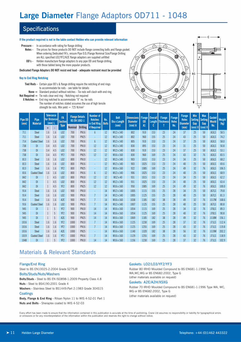
If the product required is not in the table contact Helden who can provide relevant information
Pressure - In accordance with rating for fl ange drilling Notes - The prices for these products DO NOT include fl ange connecting bolts and fl ange gasket. When ordering Dedicated FA’s, ensure Pipe O.D./Flange Nominal Size/Flange Drilling are ALL specifi ed LO2/YF2/A2E fl ange adaptors are supplied unfi tted OD’s - Helden manufacture fl ange adaptors to any pipe OD and fl ange drilling, with those tabled being the more popular products.
Dedicated Flange Adaptors DO NOT resist end load - adequate restraint must be provided
Key to End Ring Notching
Tied Rods - Certain pipe OD’s & fl ange drilling require the notching of end rings to accommodate tie rods - see table for details None = Standard product without notches - Tie rods will clash with end ring Not Required = Tie rods clear end ring - Notching not required X Notches = End ring notched to accommodate “X” no. tie rods The number of notches stated assumes the use of high tensile strength tie rods. Min yield = 725 N/mm2
Every effort has been made to ensure that the information contained in this publication is accurate at the time of publishing. Crane Ltd assumes no responsibility or liability for typographical errorsor omissions or for any misinterpretation of the information within the publication and reserves the right to change without notice.
Materials & Relevant Standards
Pipe OD(mm)
PipeMaterial
Tolerancefor Distance
(mm) L
FASection
Type
Flange DetailsBS EN 1092-1
Number ofNotches
in End Ringif Required
No.Bolts
Bolt Dia x Length
(mm)
Dimensions Diameter(mm) A
FlangeODA1
Overall Length
C
Flange Thickness
T
FlangeHolesNo.
Flange Holes
Diameter(mm)
Min Setting
Gap (mm) X
Max Setting
Gap (mm) X
Gasket Mould
No.
Weight(kg)
Nominal Drilling+ -711 Steel 1.6 1.6 LO2 700 PN16 6 12 M12 x 140 802 910 153 23 24 37 25 50 J63LS 58.5711 Steel 1.6 1.6 LO2 700 PN25 - 12 M12 x 140 802 960 155 25 24 43 25 50 J63LS 74.2714 Coated Steel 1.6 1.6 LO2 700 PN16 6 12 M12 x 140 805 910 153 23 24 37 25 50 J63LS 58.0738 DI 3.4 4.5 LO2 700 PN10 12 12 M12 x 140 830 895 153 23 24 31 25 50 J63LS 50.8738 DI 3.4 4.5 LO2 700 PN16 12 12 M12 x 140 830 910 153 23 24 37 25 50 J63LS 53.1738 DI 3.4 4.5 YF2 700 PN25 12 12 M16 x 160 830 960 169 25 24 43 32 76 J63LS 83.5813 Steel 1.6 1.6 LO2 800 PN10 - 12 M12 x 140 903 1015 153 23 24 34 25 50 J65LS 68.2813 Steel 1.6 1.6 LO2 800 PN16 - 12 M12 x 140 903 1025 153 23 24 40 25 50 J65LS 69.6813 Steel 1.6 1.6 YF2 800 PN25 - 12 M16 x 160 922 1085 169 25 24 49 32 76 J65LS 106.5816 Coated Steel 1.6 1.6 LO2 800 PN16 6 12 M12 x 140 906 1025 153 23 24 40 25 50 J65LS 68.9842 DI 1 4.5 LO2 800 PN10 12 12 M12 x 40 931 1015 153 23 24 34 25 50 J65LS 62.2842 DI 1 4.5 LO2 800 PN16 12 12 M12 x 140 931 1025 153 23 24 40 25 50 J65LS 63.4842 DI 1 4.5 YF2 800 PN25 12 12 M16 x 160 950 1085 169 25 24 49 32 76 J65LS 100.0914 Steel 1.6 1.6 LO2 900 PN10 - 14 M12 x 140 1005 1115 155 25 28 34 25 50 J67LS 79.8914 Steel 1.6 1.6 LO2 900 PN16 7 14 M12 x 140 1005 1125 155 25 28 40 25 50 J67LS 81.3914 Steel 1.6 1.6 A2E 900 PN25 7 14 M16 x 160 1038 1185 182 38 28 49 32 76 J117M 168.6916 Coated Steel 1.6 1.6 LO2 900 PN16 7 14 M12 x 140 1007 1125 155 25 28 40 25 50 J67LS 80.8945 DI 1 5 YF2 900 PN10 14 14 M16 x 160 1054 1115 169 25 28 34 32 76 J70LS 89.3945 DI 1 5 YF2 900 PN16 14 14 M16 x 160 1054 1125 169 25 28 40 32 76 J70LS 90.8945 DI 1 5 A2E 900 PN25 14 14 M16 x 160 1069 1185 182 38 28 49 32 76 J118M 156.1
1016 Steel 1.6 1.6 YF2 1000 PN10 7 14 M16 x 160 1125 1230 169 25 28 37 32 76 J71LS 112.41016 Steel 1.6 1.6 YF2 1000 PN16 7 14 M16 x 160 1125 1255 169 25 28 43 32 76 J71LS 119.81016 Steel 1.6 1.6 A2E 1000 PN25 - 14 M16 x 160 1140 1320 182 38 28 56 32 76 J119M 202.21019 Coated Steel 1.6 1.6 YF2 1000 PN16 7 14 M16 x 160 1129 1255 169 25 28 43 32 76 J71LS 118.91048 DI 1 5 YF2 1000 PN10 14 14 M16 x 160 1156 1230 169 25 28 37 32 76 J71LS 102.9
Flange/End RingSteel to BS EN10025-2:2004 Grade S275JR
Bolts/Studs/Nuts/WashersBolts/Studs - Steel to BS EN ISO898-1:2009 Property Class 4.8
Nuts - Steel to BS4190:2001 Grade 4
Washers - Stainless Steel to BS1449:Part 2:1983 Grade 304S15
CoatingsBody, Flange & End Ring - Rilsan Nylon 11 to WIS 4-52-01 Part 1
Nuts and Bolts - Sheraplex coated to WIS 4-52-03
Gaskets: LO2/LO3/YF2/YF3Rubber 80 IRHD Moulded Compound to BS EN681-1:1996 Type WA,WC,WG or BS EN682:2002, Type G (other materials available on request)
Gaskets: A2E/A2H/XSXGRubber 70 IRHD Moulded Compound to BS EN681-1:1996 Type WA, WC, WG or BS EN682:2002, Type G
(other materials available on request)
Specifications
Large Diameter Flange Adaptors OD1048 - 1663
12Helden Large Diameterwww.helden-web.com
A
X
C
A1
T
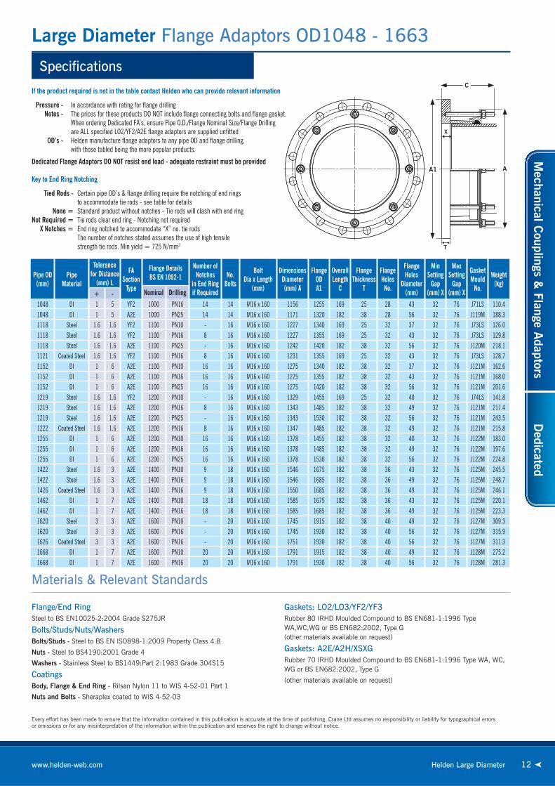
If the product required is not in the table contact Helden who can provide relevant information
Pressure - In accordance with rating for fl ange drilling Notes - The prices for these products DO NOT include fl ange connecting bolts and fl ange gasket. When ordering Dedicated FA’s, ensure Pipe O.D./Flange Nominal Size/Flange Drilling are ALL specifi ed LO2/YF2/A2E fl ange adaptors are supplied unfi tted OD’s - Helden manufacture fl ange adaptors to any pipe OD and fl ange drilling, with those tabled being the more popular products.
Dedicated Flange Adaptors DO NOT resist end load - adequate restraint must be provided
Key to End Ring Notching
Tied Rods - Certain pipe OD’s & fl ange drilling require the notching of end rings to accommodate tie rods - see table for details None = Standard product without notches - Tie rods will clash with end ring Not Required = Tie rods clear end ring - Notching not required X Notches = End ring notched to accommodate “X” no. tie rods The number of notches stated assumes the use of high tensile strength tie rods. Min yield = 725 N/mm2
Every effort has been made to ensure that the information contained in this publication is accurate at the time of publishing. Crane Ltd assumes no responsibility or liability for typographical errorsor omissions or for any misinterpretation of the information within the publication and reserves the right to change without notice.
Materials & Relevant Standards
Pipe OD(mm)
PipeMaterial
Tolerancefor Distance
(mm) L
FASection
Type
Flange DetailsBS EN 1092-1
Number ofNotches
in End Ringif Required
No.Bolts
Bolt Dia x Length
(mm)
Dimensions Diameter(mm) A
FlangeODA1
Overall Length
C
Flange Thickness
T
FlangeHolesNo.
Flange Holes
Diameter(mm)
Min Setting
Gap (mm) X
Max Setting
Gap (mm) X
Gasket Mould
No.
Weight(kg)
Nominal Drilling+ -1048 DI 1 5 YF2 1000 PN16 14 14 M16 x 160 1156 1255 169 25 28 43 32 76 J71LS 110.41048 DI 1 5 A2E 1000 PN25 14 14 M16 x 160 1171 1320 182 38 28 56 32 76 J119M 188.31118 Steel 1.6 1.6 YF2 1100 PN10 - 16 M16 x 160 1227 1340 169 25 32 37 32 76 J73LS 126.01118 Steel 1.6 1.6 YF2 1100 PN16 8 16 M16 x 160 1227 1355 169 25 32 43 32 76 J73LS 129.81118 Steel 1.6 1.6 A2E 1100 PN25 - 16 M16 x 160 1242 1420 182 38 32 56 32 76 J120M 218.11121 Coated Steel 1.6 1.6 YF2 1100 PN16 8 16 M16 x 160 1231 1355 169 25 32 43 32 76 J73LS 128.71152 DI 1 6 A2E 1100 PN10 16 16 M16 x 160 1275 1340 182 38 32 37 32 76 J121M 162.61152 DI 1 6 A2E 1100 PN16 16 16 M16 x 160 1275 1355 182 38 32 43 32 76 J121M 168.01152 DI 1 6 A2E 1100 PN25 16 16 M16 x 160 1275 1420 182 38 32 56 32 76 J121M 201.61219 Steel 1.6 1.6 YF2 1200 PN10 - 16 M16 x 160 1329 1455 169 25 32 40 32 76 J74LS 141.81219 Steel 1.6 1.6 A2E 1200 PN16 8 16 M16 x 160 1343 1485 182 38 32 49 32 76 J121M 217.41219 Steel 1.6 1.6 A2E 1200 PN25 - 16 M16 x 160 1343 1530 182 38 32 56 32 76 J121M 243.51222 Coated Steel 1.6 1.6 A2E 1200 PN16 8 16 M16 x 160 1347 1485 182 38 32 49 32 76 J121M 215.81255 DI 1 6 A2E 1200 PN10 16 16 M16 x 160 1378 1455 182 38 32 40 32 76 J122M 183.01255 DI 1 6 A2E 1200 PN16 16 16 M16 x 160 1378 1485 182 38 32 49 32 76 J122M 197.61255 DI 1 6 A2E 1200 PN25 16 16 M16 x 160 1378 1530 182 38 32 56 32 76 J122M 224.81422 Steel 1.6 3 A2E 1400 PN10 9 18 M16 x 160 1546 1675 182 38 36 43 32 76 J125M 245.51422 Steel 1.6 3 A2E 1400 PN16 9 18 M16 x 160 1546 1685 182 38 36 49 32 76 J125M 248.71426 Coated Steel 1.6 3 A2E 1400 PN16 9 18 M16 x 160 1550 1685 182 38 36 49 32 76 J125M 246.11462 DI 1 7 A2E 1400 PN10 18 18 M16 x 160 1585 1675 182 38 36 43 32 76 J125M 220.11462 DI 1 7 A2E 1400 PN16 18 18 M16 x 160 1585 1685 182 38 36 49 32 76 J125M 223.31620 Steel 3 3 A2E 1600 PN10 - 20 M16 x 160 1745 1915 182 38 40 49 32 76 J127M 309.31620 Steel 3 3 A2E 1600 PN16 - 20 M16 x 160 1745 1930 182 38 40 56 32 76 J127M 315.91626 Coated Steel 3 3 A2E 1600 PN16 - 20 M16 x 160 1751 1930 182 38 40 56 32 76 J127M 311.31668 DI 1 7 A2E 1600 PN10 20 20 M16 x 160 1791 1915 182 38 40 49 32 76 J128M 275.21668 DI 1 7 A2E 1600 PN16 20 20 M16 x 160 1791 1930 182 38 40 56 32 76 J128M 281.3
Flange/End RingSteel to BS EN10025-2:2004 Grade S275JR
Bolts/Studs/Nuts/WashersBolts/Studs - Steel to BS EN ISO898-1:2009 Property Class 4.8
Nuts - Steel to BS4190:2001 Grade 4
Washers - Stainless Steel to BS1449:Part 2:1983 Grade 304S15
CoatingsBody, Flange & End Ring - Rilsan Nylon 11 to WIS 4-52-01 Part 1
Nuts and Bolts - Sheraplex coated to WIS 4-52-03
Gaskets: LO2/LO3/YF2/YF3Rubber 80 IRHD Moulded Compound to BS EN681-1:1996 Type WA,WC,WG or BS EN682:2002, Type G (other materials available on request)
Gaskets: A2E/A2H/XSXGRubber 70 IRHD Moulded Compound to BS EN681-1:1996 Type WA, WC, WG or BS EN682:2002, Type G
(other materials available on request)
Mechanical C
ouplings & Flange A
daptorsD
edicated

Large Diameter Check list
13 Telephone: +44 (0)1462 44332213 Helden Large Diameter
Ductile Iron Cast Iron Steel StainlessSteel
PVC PE HEP30 GRP
ABS Clay Concrete AsbestosCement
Copper Lead
Other(Please specify)
Date
Quantity
Fax
TelephoneCustomer Address
Company Name
EmailContact Name
Delivery Date
Pipe Details
Outside Diameter
Pipe Material
Outside Diameter Tolerances
Flange Rating
Packaging & Carriage Requirements
(Please tick)
Pipe Coating Thickness
Pipe Coating (Especially important on steel pipes)
Working/Test/Design Pressure
Coating Required
Gasket Grade Required or medium conveyed
Product Requirements
Drilling Pattern
Locating Plugs (If required)
Any Special Documents / Inspection Requirements
Any Other Special Requirements
Large Diameter is a bespoke product and Helden requires the following information to assist with the quotation process.This page can be copied from the brochure or a form is available on the website or directly from the Marketing Department.
Please fax back to: +44 (0)1462 443311 or email to: [email protected]
ISO 9001FM 00311
ISO 14001EMS 51874
www.flowoffluids.com
www.cranebsu.com
www.helden-web.com
■ Designed and manufactured under quality management systems in accordance with BS EN ISO 9001.
■ Environmental Management System accredited to ISO 14001.
■ For full terms and conditions, please visit our website.
DR
5688
_04_
2011
46-48 WILBURY WAYHITCHIN, HERTFORDSHIRESG4 0UD. UNITED KINGDOM
TELEPHONE: +44 (0)1462 443322FAX: +44 (0)1462 443311EMAIL: [email protected]
Visit www.fl owoffl uids.com to order yourcopy of the New Technical Paper 410.
Every effort has been made to ensure that the information contained in this publication is accurate at the time of publishing. Crane Ltd assumes no responsibilityor liability for typographical errors or omissions or for any misinterpretation of the information within the publication and reserves the right to change without notice.