DR400 Maintenance Schedule Is5 Amdt7 April2015
46
Doc. no. 1001586GB DR400 AIRWORTHINESS LIMITATIONS & MAINTENANCE SCHEDULE Issue 5 - March 2013 Page 1 of 36 C.E.A.P.R. 1, route de Troyes 21121 DAROIS – France Tel. + 33 (0)3 80 35 25 22 Fax. + 33 (0)3 80 35 25 25 Website: www.ceapr.com DR400 AIRWORTHINESS LIMITATIONS & MAINTENANCE SCHEDULE This document together with the DR400 Maintenance Manual (doc n° 1001606), contain appropriate instructions for continued airworthiness as described in § CS 23.1529 of Certification Specifications CS 23. The English version of this document is a courtesy translation of its original French version. In case of any difficulty, reference should be made to the French original issue. ISSUE 5 dated MARCH 2013 Document n°1001586
description
DR 400 Maintenance Schedule
Transcript of DR400 Maintenance Schedule Is5 Amdt7 April2015

Doc. no. 1001586GB DR400 AIRWORTHINESS LIMITATIONS & MAINTENANCE SCHEDULE
Issue 5 - March 2013 Page 1 of 36
C.E.A.P.R. 1, route de Troyes
21121 DAROIS – France Tel. + 33 (0)3 80 35 25 22 Fax. + 33 (0)3 80 35 25 25
Website: www.ceapr.com
DR400
AIRWORTHINESS LIMITATIONS
&
MAINTENANCE SCHEDULE
This document together with the DR400 Maintenance Manual (doc n° 1001606), contain appropriate instructions for continued airworthiness as described in § CS 23.1529 of Certification Specifications CS 23.
The English version of this document is a courtesy translation of its original French version. In case of any difficulty, reference should be made to the French original issue.
ISSUE 5 dated
MARCH 2013 Document n°1001586
Doc. no. 1001586GB DR400 AIRWORTHINESS LIMITATIONS & MAINTENANCE SCHEDULE
Page 2 of 36 Issue 4 - July 2006

Doc. no. 1001586GB DR400 AIRWORTHINESS LIMITATIONS & MAINTENANCE SCHEDULE
Issue 5 - March 2013 Page 3 of 36
TABLE OF CONTENT
List of current pages
Record of amendments
Chapter I AIRWORTHINESS LIMITATIONS
Chapter II MAINTENANCE SCHEDULE
Section 1 General instructions
Section 2 Time between inspections and weighing
Section 3 Instructions for maintenance, operation and stocking of components and equipments
Section 4 Specific maintenance operations
Section 5 Control flights
Section 6 Maintenance operations table

Doc. no. 1001586GB DR400 AIRWORTHINESS LIMITATIONS & MAINTENANCE SCHEDULE
Page 4 of 36 Amendment 7 dated April 2015 Issue 5 - March 2013
LIST OF CURRENT PAGES
Amendment Date
Cover ...................................................Original ...........................March 2013
1st page ..............................................Original ...........................March 2013
Table of content ...................................Original ...........................March 2013
List of current pages.................................. 7 .................................. April 2015
Record of amendments ............................ 7 .................................. April 2015
Chapter I - Airworthiness limitations Amendment Date
All the pages ........................................Original ...........................March 2013
Chapter II - Maintenance schedule
Amendment Date
Section 1 ..............................................Original ...........................March 2013
Section 2 .............................................Original ...........................March 2013
Section 3 .................................................. 5 .................................. June 2014
Section 4 .............................................Original ...........................March 2013
Section 5 .............................................Original ...........................March 2013
Section 6 .................................................. 7 .................................. April 2015 Annex ............................................... 7 .................................. April 2015

Doc. no. 1001586GB DR400 AIRWORTHINESS LIMITATIONS & MAINTENANCE SCHEDULE
Issue 5 - March 2013 Amendment 7 dated April 2015 Page 5 of 36
RECORD OF AMENDMENTS
Amendment 1 dated April 2013
PAGE TO DELETE PAGE TO INSERT REASON
Page 4 of 36 “List of current
pages” original Page 5 of 36 “Record of
amendments” original Annex original in section 6
Page 4 of 36 “List of current
pages” Amdt 1 Page 5 of 36 “Record of
amendments” Amdt 1 Annex (all pages), amdt 1
dated April 2013
Updating Updating Modification of annex part of section 6, line 57-20.
Amendment 2 dated June 2013
PAGE TO DELETE PAGE TO INSERT REASON
Page 4 of 36 “List of current pages” Amdt 1 Page 5 of 36 “Record of amendments” Amdt 1 Section 3
Annex (all pages), amdt 1 dated April 2013
Page 4 of 36 “List of current pages” Amdt 2 Page 5 of 36 “Record of amendments” Amdt 2 Section 3 Amdt 2
Annex (all pages), amdt 2 dated June 2013
Updating Updating Modification of table 2 Modification of “Additional instructions”
Modification of annex part of section 6, line 71-55.
Amendment 3 dated June 2013
PAGE TO DELETE PAGE TO INSERT REASON
Page 4 of 36 “List of current pages” Amdt 2 Page 5 of 36 “Record of amendments” Amdt 2 Section6 Annex (all pages),
amdt 2 dated June 2013
Page 4 of 36 “List of current pages” Amdt 3 Page 5 of 36 “Record of amendments” Amdt 3 Section6 Annex (all pages),
amdt 3 dated June 2013
Updating Updating Modification of annex part of section 6, line 27-130 and line 57-70.
Amendment 4 dated October 2013
PAGE TO DELETE PAGE TO INSERT REASON
Page 4 of 36 “List of current pages” Amdt 3 Page 5 of 36 “Record of amendments” Amdt 3 Section 3
Page 4 of 36 “List of current pages” Amdt 4 Page 5 of 36 “Record of amendments” Amdt 4 Section 3
Updating Updating Modification of table 2
Note: Each "record of amendments" page must be kept in the manual throughout its life.
The availability of all the pages allows giving a chronological account of changes.
Doc. no. 1001586GB DR400 AIRWORTHINESS LIMITATIONS & MAINTENANCE SCHEDULE
Page 6 of 36 Amendment 7 dated April 2015 Issue 5 - March 2013
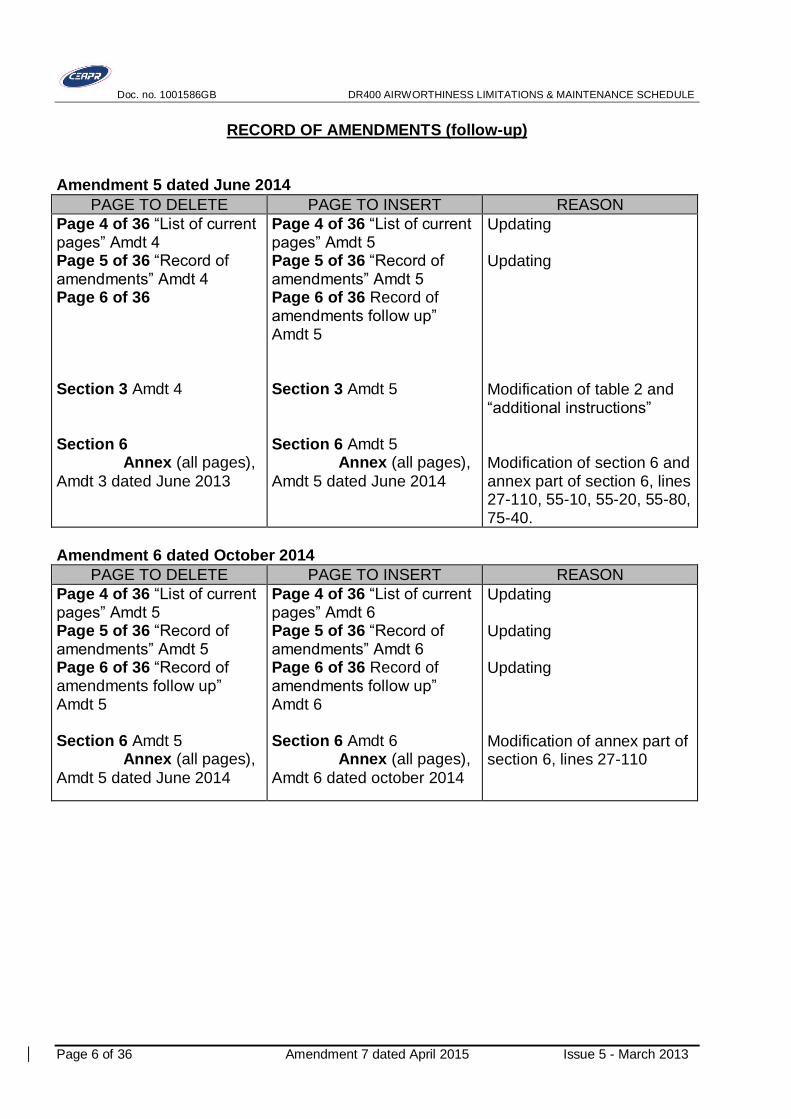
RECORD OF AMENDMENTS (follow-up)
Amendment 5 dated June 2014
PAGE TO DELETE PAGE TO INSERT REASON
Page 4 of 36 “List of current pages” Amdt 4 Page 5 of 36 “Record of amendments” Amdt 4 Page 6 of 36 Section 3 Amdt 4
Section 6 Annex (all pages),
Amdt 3 dated June 2013
Page 4 of 36 “List of current pages” Amdt 5 Page 5 of 36 “Record of amendments” Amdt 5 Page 6 of 36 Record of amendments follow up” Amdt 5
Section 3 Amdt 5
Section 6 Amdt 5 Annex (all pages),
Amdt 5 dated June 2014
Updating Updating Modification of table 2 and “additional instructions” Modification of section 6 and annex part of section 6, lines 27-110, 55-10, 55-20, 55-80, 75-40.
Amendment 6 dated October 2014
PAGE TO DELETE PAGE TO INSERT REASON
Page 4 of 36 “List of current pages” Amdt 5 Page 5 of 36 “Record of amendments” Amdt 5 Page 6 of 36 “Record of amendments follow up” Amdt 5 Section 6 Amdt 5 Annex (all pages),
Amdt 5 dated June 2014
Page 4 of 36 “List of current pages” Amdt 6 Page 5 of 36 “Record of amendments” Amdt 6 Page 6 of 36 Record of amendments follow up” Amdt 6 Section 6 Amdt 6 Annex (all pages),
Amdt 6 dated october 2014
Updating Updating Updating Modification of annex part of section 6, lines 27-110

Doc. no. 1001586GB DR400 AIRWORTHINESS LIMITATIONS & MAINTENANCE SCHEDULE
Issue 5 - March 2013 Amendment 7 dated April 2015 Page 7 of 36
RECORD OF AMENDMENTS (follow-up)
Amendment 7 dated April 2015
PAGE TO DELETE PAGE TO INSERT REASON
Page 4 of 36 “List of current
pages” Amdt 6 Page 5 of 36 “Record of
amendments” Amdt 5 Page 6&7 of 36 “Record of
amendments follow up” Amdt 7 Section 6 Amdt 6 Annex (all pages), Amdt 6 dated October 2014
Page 4 of 36 “List of current
pages” Amdt 6 Page 5 of 36 “Record of
amendments” Amdt 6 Page 6&7 of 36 Record of
amendments follow up” Amdt 7 Section 6 Amdt 7 Annex (all pages), Amdt 7 dated April 2015
Updating Updating Updating Addition of Note 29 & 30 Modification of annex part of section 6, lines 21.20/ 24.10/ 24.120/ 25.10/ 27.10/ 27.20/ 27.150/ 31.10/ 32.50/ 32.55/ 32.220/ 53.10/ 53.30/ 57.10/ 57.70/ 61.10/ 61.20/ 73.100/ 75.30/ 75.50
Note: Each "record of amendments" page must be kept in the manual throughout its life.
The availability of all the pages allows giving a chronological account of changes.

Doc. no. 1001586GB DR400 AIRWORTHINESS LIMITATIONS & MAINTENANCE SCHEDULE
Page 8 of 36 Amendment 7 dated April 2015 Issue 5 - March 2013

Doc. no. 1001586GB Chapter I DR400 AIRWORTHINESS LIMITATIONS
Issue 5 - March 2013 Page 9 of 36
Chapter I
DR400
AIRWORTHINESS LIMITATIONS
The airworthiness limitations are approved by the European Aviation Safety Agency (EASA).
Any change in the chapter "AIRWORTHINESS LIMITATIONS" shall be
presented to the European Aviation Safety Agency for approval.

Doc. no. 1001586GB Chapter I DR400 AIRWORTHINESS LIMITATIONS
Page 10 of 36 Issue 5 - March 2013
AIRWORTHINESS LIMITATIONS
The DR400 airplanes, any model, are not subject to Airworthiness limitations.
Note 1: The Airworthiness Limitations of DR400 fitted with STC EASA 10014219 “Installation of TAE 125-01 engine” (DR400/135CDI) are included in the following documents:
- Doc. 1001586, DR400 Airworthiness limitations & Maintenance schedule. - Doc. OM-02-01, Operation & Maintenance Manual TAE 125-01. - Doc. AMM-60-01, Supplement Airplane Maintenance Manual Robin DR400/135CDI –
TAE 125-01.
Note 2: The Airworthiness Limitations of DR400 fitted with STC EASA 10014219 “Installation of TAE 125-02-99 engine and installation of FADEC backup battery” (DR400/135CDI) are included in the following documents:
- Doc. 1001586, DR400 Airworthiness limitations & Maintenance schedule. - Doc. OM-02-02, Operation & Maintenance Manual TAE 125-02-99. - Doc. AMM-60-02, Supplement Airplane Maintenance Manual Robin DR400/135CDI –
CENTURION 2.0.
Note 3: The Airworthiness Limitations of DR400 fitted with STC EASA 10014219 “Installation of TAE 125-02-114” (DR400/155CDI) are included in the following documents:
- Doc. 1001586, DR400 Airworthiness limitations & Maintenance schedule. - Doc. OM-02-02, Operation & Maintenance Manual TAE 125-02-99. - Doc. AMM-60-02S, Supplement Airplane Maintenance Manual Robin DR400/155CDI –
CENTURION 2.0S.

Doc. no. 1001586GB Chapter II DR400 MAINTENANCE SCHEDULE
Issue 5 - March 2013 Page 11 of 36
Chapter II
DR400
MAINTENANCE SCHEDULE
Maintenance schedule applicable to DR400 all models except DR400 RP and 125i:
DR 400/125 DR 400/140 DR 400/160 DR 400/180 DR 400/180 R DR 400/2+2 DR 400/120 DR 400/140 B (*) DR 400/120 A DR 400/160 D DR 400/120 D DR 400/180 S DR 400/100 DR 400 NGL DR 400/200 R DR 400/500
(*) Note: Specificity of DR 400/140 B with STC EASA 10014219: TAE 125 engine installation (DR 400/135CDI, DR 400/155CDI) is described in TAE documents.
This document is proposed as a sample and contains all data from manufacturer useful to make the maintenance schedule dedicated to the plane and approved. The reference regulation applied is the one of EASA together with the French specificities taken into account.

Doc. no. 1001586GB Chapter II DR400 MAINTENANCE SCHEDULE
Page 12 of 36 Issue 5 - March 2013

Doc. no. 1001586GB Chapter II DR400 MAINTENANCE SCHEDULE
Issue 5 - March 2013 Page 13 of 36
SECTION 1
GENERAL INSTRUCTIONS
A. GENERAL
The owner/operator or the person in charge for the management of the continued airworthiness must make sure that the inspections appearing in the maintenance schedule are carried out in the prescribed intervals.
Nothing of what is contained or omitted in the maintenance schedule discharges the owner/operator from the responsibility to make sure that the aircraft is maintained airworthy.
The maintenance schedule must hold account of the operational requirements, as well as all requirements of maintenance rising from the modifications or repairs.
The modifications made to the maintenance manual must be accepted by the qualified services.
The owner/operator must modify its maintenance schedule according to directives of the qualified services, the publications delivered by the manufacturers (service bulletins, revisions to the maintenance documents…), the maintenance documents of the manufacturers following a modification. This update is carried out within one year as from the diffusion of the requirement of the authority or the recommendations of the manufacturer. A personalized follow-up must be set up to carry out these inspections in waiting of their insertion in the program.
The specificities of the country in which the aircraft is registered must be taken into account.
B. DEFINITION OF MAINTENANCE
Maintenance, with preventive vocation for all the components taking part in the airworthiness condition, is composed of the whole of the operations which contribute to maintain the aircraft on a satisfactory level of safety. It incorporates generally:
inspections: examinations of various levels, having for goal to objectively recognize the state of a component;
specific actions, predetermined or not: interventions for purpose of conservation, like corrective actions resulting from the;
replacements of components in the given term;
Particular operations having the aim of making sure of continued operational features or consecutive to certain unforeseeable occurrences.
Accordingly, the maintenance schedule is a document which describes the operations necessary to maintain the aptitude of an aircraft for being operated, in particular as regards aptitude for the flight, of maintenance of the equipment as of the means of radio communication/navigation whose presence on board is required by the regulation.
The application of the airworthiness directives is managed in a way personalized to each airplane.

Doc. no. 1001586GB Chapter II DR400 MAINTENANCE SCHEDULE
Page 14 of 36 Issue 5 - March 2013
C. COMPLEX MAINTENANCE TASKS – FLIGHT SAFETY SENSITIVE MAINTENANCE TASKS
Complex maintenance tasks referred to in M.A. 801 (b), 2. : 1) The modification, repair or replacement by riveting, bonding, laminating, or welding of
any of the following airframe parts: a. a box beam; b. a wing stringer or chord member; c. a spar; d. a spar flange; e. a member of a truss-type beam; f. the web of a beam; g. a corrugated sheet compression member in a wing or tail surface; h. a wing main rib; i. a wing or tail surface brace strut; j. an engine mount; k. a fuselage longeron or frame; l. a member of a side truss, horizontal truss or bulkhead; m. a seat support brace or bracket; n. a seat rail replacement; o. a landing gear strut or brace strut; p. an axle; q. a wheel.
2) The modification or repair of any of the following parts:
a. Aircraft skin if the work requires the use of a support, jig or fixture; b. A load-bearing part of a control system, including a control column, pedal, shaft,
quadrant, bell crank, torque tube, control horn and forged or cast bracket, but excluding:
- the swaging of a repair splice or cable fitting, and - the replacement of a push-pull tube end fitting that is attached by riveting;
and
c. Any other structure, not listed in (1), which a manufacturer has identified as primary structure in its maintenance manual, structural repair manual or instructions for continuing airworthiness.
Doc. no. 1001586GB Chapter II DR400 MAINTENANCE SCHEDULE
Issue 5 - March 2013 Page 15 of 36
Flight safety sensitive maintenance tasks (M.A. 402(a)):
- The tasks for which the manufacturer's documentation has explicitly planned an independent inspection;
- At least: a practical work on a control system which, in case of errors, could lead to a failure, a malfunction or a defect threatening flight safety. A control system is a system of the aircraft which may change the flight path, the flight attitude or the propulsive force of the aircraft, Notably the flight controls, the engine and propeller, the related control systems and the associated operating mechanisms.
Examples of possibly sensitive maintenance tasks:
- Installation, setting and adjustment of flight controls. - Installation of engines, propellers on aircraft. - Overhaul calibration or adjustment of components such as engines, propellers,
transmissions and gearboxes. It is the responsibility of the person who issues the “aircraft Certificate of Release to Service” (CRS) to assess how critical is the maintenance task carried out so as to determine the need for an independent inspection. It must also take into account for this evaluation; knowledge on how experienced is the person who performed the tasks involved. Under AMC at § M.A. 402(a), “independent inspection” means an inspection carried out by a person other than the one that made the task to be checked.
However for airplanes less than 2730 kg that are not complex motorized airplanes, alternate solutions may be proposed for the approval of the authority (example: self-inspection, if not simply taking in the same order, the steps already completed, but including verification points that do not assume to know how was performed the task to be checked).
A special inspection shall be carried out after any flight safety sensitive maintenance task unless otherwise specified by Part-145 or agreed by the competent authority.
Doc. no. 1001586GB Chapter II DR400 MAINTENANCE SCHEDULE
Page 16 of 36 Issue 5 - March 2013
C. TERMINOLOGY
Flight time Definition Breakdown time since the aircraft starts moving towards the runway by means of its own power plant till the time it stops at the end of the flight.
Routine inspection Overall inspection or test of good jettisoning. It enables to check the good working order of an assembly of the aircraft without forcing to a removal.
Visual investigation or visual check It is one of the components of the above mentioned routine inspection. The aim is to ensure carefully that a given element is in good serviceable conditions. This investigation is carried out visually, “in situ”. Example: Search for cracks or corrosion.
Detailed inspection Consists in a complete examination of a part or an assembly with removal if necessary in order to detect defective parts and foresee which ones could lead to catastrophe.
Detailed investigation or detailed check It is one of the components of the detailed inspection. It consists in an accurate examination of an element either visually, after removal, or with the help of magnifying glass or the help of another means of investigation (dye-penetrant inspection, magnetic particle inspection, eddy current…).
Verification It is one of the components of both routine inspection and detailed inspection. It is an operation through which an element is checked to ensure its compliance, or state, possibly using a measuring instrument. Example: verification of the tension of control cables.
Bench test Complete operating test following removal of the equipment on a bench test in a workshop. It leads to establish technical records.
Operational test Operation only necessary to make sure that a system or equipment is in good working condition. These tests do not require any special equipment or any special installation other than those required on the aircraft (power supply). They must be comparable to those carried out by the operation crew.
Functional test This test is only used to ascertain that a system or component functions in every way according to the minimum acceptable specification in relation to the original design of the system or the equipment. This test can require a11itional ground equipment and must be more detailed and precise than operational test. The definition of this test must include all means necessary to conduct these tests allowing the possibility of maintaining the reliability of systems or equipment at an acceptable level. Requires a report to be done.
Calendar time inspection (aging inspection) Consists in a routine or detailed inspection depending on the maintenance operation table column, with calendar time interval, to detect defective parts or conditions due to aging (storage …).
Doc. no. 1001586GB Chapter II DR400 MAINTENANCE SCHEDULE
Issue 5 - March 2013 Page 17 of 36
Global Test Test using radiation, with no removal, by means of specialized benches.
Life Limit Time after which a life timed equipment must be replaced (example for radio: ELT batteries).
D. ABBREVIATIONS
ADF: Automatic Direction Finder
AD: Airworthiness Directive
CN: Airworthiness Directive (Consigne de Navigabilité)
DGAC: French authority (Direction Générale de l’Aéronautique Civile)
ED: Detailed examination (Examen Détaillé)
ER: Maintenance and repair (Entretien et Réparation)
EV: Visual investigation or visual check (Examen Visuel)
GSAC: French authority (Groupement pour la Sécurité de l’Aviation Civile)
h: Flight hours
IFR: Instrument Flight Rule
IRB: Radio equipment (Installation Radioélectrique de Bord)
OE: Maintenance facility (Organisme d’Entretien)
PB: Bench test (Essai – Passage – au Banc)
PH: Propeller time between overhaul (Potentiel Hélice)
PM: Engine time between overhaul (Potentiel Moteur)
RBDA: Emergency locator Transmitter ELT (Radio-Balise à Détection Automatique)
RG: Complete overhaul (Révision Générale)
ROS: Standing Waves Ratio SWR (Rapport d’Ondes Stationnaires)
SB: Service Bulletin
SL: Service Lettre
TAE: Thielert Aircraft Engines
TFAR: Time between servicing (Temps de Fonctionnement Avant Révision)
TG: Global Test (Test Global)
TL: Time between overhaul TBO (Temps Limite d’utilisation avant R.G.)
VA: One year interval inspection (Visite Annuelle)
VE: Condition check (Vérification de l’Etat)
VFR: Visual Flight Rules
VHF: Very High Frequency radio equipment
VL: Life limit (Vie Limite)

Doc. no. 1001586GB Chapter II DR400 MAINTENANCE SCHEDULE
Page 18 of 36 Issue 5 - March 2013
E. REFERENCE MAINTENANCE DOCUMENTS (latest issue): Maintenance of DR400 must be performed with document n°1001586 and following engine and propellers documents:
Document Reference
DR400 Maintenance manual Doc. 1001606 GB
DR400/500 Maintenance manual Doc. 1001870 GB
DR400 Service Bulletins (current issue)
DR400 Service Letters (current issue)
Lycoming Engine Service Bulletins (current issue)
Service Letters (current issue)
Service Instructions (current issue)
Operator’s manual O-235 and O-290 series 60297-9
Operator’s manual O-320 series 60297-30
Operator’s manual O-360 series, IO-360 60297-12
Propellers Operation and installation manual of various propeller manufacturers
Various
Note 1: The maintenance schedule of DR400 fitted with STC EASA 10014219 “Installation of TAE 125-01 engine” (DR400/135CDI) comprises the following documents: - Doc. 1001586, DR400 Airworthiness limitations & Maintenance schedule. - Doc. OM-02-01, Operation & Maintenance Manual TAE 125-01. - Doc. AMM-60-01, Supplement Airplane Maintenance Manual Robin DR400/135CDI –
TAE 125-01. - TAE Service Bulletins (SB) & Service Letters (SL) (current issue). - MT-Propeller Operation and installation manual (ATA 61-01-24 E-124) & current SBs. Note 2: The maintenance schedule of DR400 fitted with STC EASA 10014219 “Installation of TAE 125-02-99 engine and installation of FADEC backup battery” (DR400/135CDI) comprises the following documents: - Doc. 1001586, DR400 Airworthiness limitations & Maintenance schedule. - Doc. OM-02-02, Operation & Maintenance Manual TAE 125-02-99. - Doc. AMM-60-02, Supplement Airplane Maintenance Manual Robin DR400/135CDI –
CENTURION 2.0. - TAE Service Bulletins (SB) & Service Letters (SL) (current issue). - MT-Propeller Operation and installation manual (ATA 61-01-24 E-124) & current SBs.
Note 3: The maintenance schedule of DR400 fitted with STC EASA 10014219 “Installation of TAE 125-02-114 engine” (DR400/155CDI) comprises the following documents:
- Doc. 1001586, DR400 Airworthiness limitations & Maintenance schedule. - Doc. OM-02-02, Operation & Maintenance Manual TAE 125-02-99. - Doc. AMM-60-02S, Supplement Airplane Maintenance Manual Robin DR400/135CDI –
CENTURION 2.0S. - TAE Service Bulletins (SB) & Service Letters (SL) (current issue). - MT-Propeller Operation and installation manual (ATA 61-01-24 E-124) & current SBs.
Doc. no. 1001586GB Chapter II DR400 MAINTENANCE SCHEDULE
Issue 5 – March 2013 Page 19 of 36
F. OPERATING CHARACTERISTICS – BREAKDOWN OF HOURS.
This maintenance schedule is established for a more or less 500 hours annual flight hours. The hours applicable to life limit and periodicity are counted-down block – block (1st turn of wheel to final stop).
Cycles and landings may be taken into account in the follow-up of the airplane.
G. UPDATING OF MAINTENANCE SCHEDULE
Any modification to the maintenance schedule content must be recorded as an amendment showing the summary of the changes to the manual and the reasons of these changes.
This updating has to be done within one year from the decision of the requirements of the authorities or the recommendations of the manufacturer.

Doc. no. 1001586GB Chapter II DR400 MAINTENANCE SCHEDULE
Page 20 of 36 Issue 5 - March 2013

Doc. no. 1001586GB Chapter II DR400 MAINTENANCE SCHEDULE
Issue 5 - March 2013 Page 21 of 36
SECTION 2
TIME BETWEEN INSPECTIONS
The aircraft must be inspected in accordance with the interval of periodic inspection per table 1. The intervals of inspection may vary within the tolerances set.
Instructions and detailed procedures related to maintenance schedule are listed in section 6.The maximum periodicity of an inspection is marked by a dot () in the relevant column.
REMINDER: MAINTENANCE INSTRUCTIONS ARE NECESSARILY CUMULATIVE Example 1: a 500 h maintenance inspection shall include instructions planned at 50 h, 100 h and 500 h. Example 2: a 3 year maintenance inspection shall include instructions planned at 1 year and 3 years.
For maintenance operations listed as routine / or detailed and with calendar time, the calendar time inspection must only be performed if no routine or detailed inspection has been performed within the calendar time interval. Example: for operation « item 25.20 », the one year interval inspection will be performed only if 100 hour routine inspection has not been done within the one year interval.
Tolerances A certain amount of tolerance is given in which to perform inspection operations, to enable a more flexible use of the aircraft. Thus, inspections related to aircraft operation may be made to coincide with calendar type inspections. Note: Permissible tolerances cannot be cumulated. Example: if a 100 h inspection is performed at 110 h, this same inspection cannot be subsequently performed at 220 h but only after a maximum of 210 h. Therefore, such tolerances cannot lead to eliminate one 100 h inspection out of ten.
Table 1: interval of periodic inspection
OPERATION PERIODICITY TOLERANCE
50 h 50 hours 10 h
100 h 100 hours 10 h
500 h 500 hours 30 h
1000 h 1000 hours 30 h
2000 h 2000 hours 30 h
1 year 1 year 1 month
3 years 3 years 2 months
6 years 6 years 2 months
Note: The tolerances apply neither to the airworthiness limitations, nor with the airworthiness directives, unless otherwise specified.

Doc. no. 1001586GB Chapter II DR400 MAINTENANCE SCHEDULE
Page 22 of 36 Issue 5 - March 2013
Weigting
Refer to Aircraft flight manual, maintenance manual….
First interval: 5 years. A weighing form with inventory is to be filled out.
Time between two weighings shall not exceed 60 months. It is tolerated that this expiry is deferred to the 1st grounding of the airplane for planned inspection occurring immediately after 60 months (cf. fascicule GSAC P-61-10).
Weighing must be carried out:
- after:
> a major modification
> a major repair
> a main conversion of interior equipment
> complete painting of the aircraft.
- each time a modification insufficiently precise of the condition of the aircraft does not allow the update weight and balance record by a simple calculation.

Doc. no. 1001586GB Chapter II DR400 MAINTENANCE SCHEDULE
Issue 5 - March 2013 amendment 5 dated June 2014 Page 23 of 36
SECTION 3
COMPONENTS AND EQUIPMENTS MAINTENANCE, USE AND STORAGE PRACTICES
The overhaul of the engines, propellers, components and equipment and the other maintenance inspections to be carried out apart from the routine intervals are carried out in accordance with the indications described in table 2.
Refer to manufacturer’s documentation at latest issue for engine and propellers.
Table 2: Various particular checks
Components with life time
DESIGNATION REFERENCE LIMIT Note 1
INTERVENTION OBSERVATIONS
REMARKS
Air filter (foam) 56.18.08.015 100 h / 1 year To exchange Serial no. > 2209 Model> year 1992
note 2
Air filter (cartridge)
56.12.59.010 56.23.02.200 56.28.10.200 56.11.13.000 57.34.00.010
200 h / 1 year To exchange Serial no. < 2210
note 2
Instrument panel vibration isolators
2000h / 10 years To exchange
Ducts (engine surrounding)
CEAPR (see catalogue)
10 years To exchange
Elastomer flexible line
CEAPR (see catalogue)
10 years To exchange Excepted teflon
Vacuum system suction hoses
CEAPR (see catalogue)
10 years To exchange
“Flûtes” and “1/4 d’onde” exhaust silencer elastometric mountings
CEAPR (see catalogue)
500 h / 5 years To exchange
Filter of the suction regulator (vacuum system)
100 h / 1 an To exchange
AIRBORNE Mandatory
Service Instruction.
Service Letter 59
Control gyro air filter of vacuum system.
500 h / 1 year To exchange
AIRBORNE Mandatory
Service Instruction.
Service Letter 59
Doc. no. 1001586GB Chapter II DR400 MAINTENANCE SCHEDULE
Page 24 of 36 amendment 5 dated June 2014 Issue 5 - March 2013
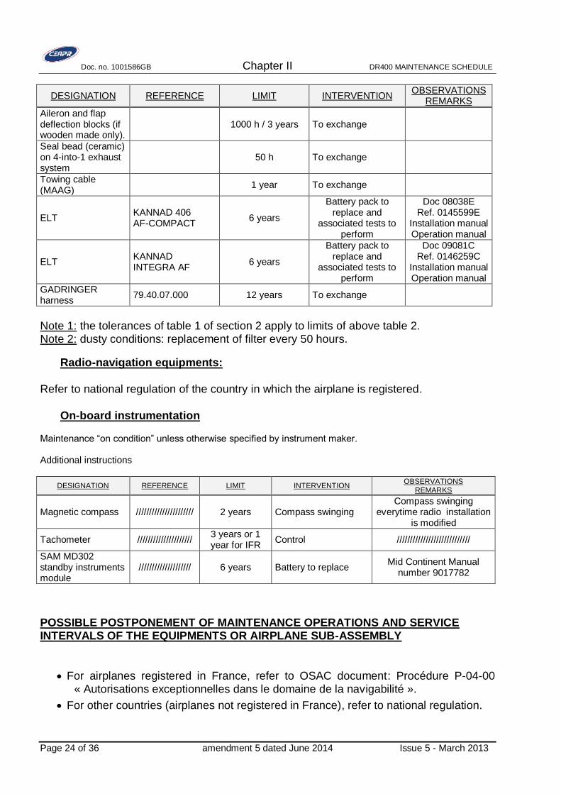
DESIGNATION REFERENCE LIMIT INTERVENTION OBSERVATIONS
REMARKS
Aileron and flap deflection blocks (if wooden made only).
1000 h / 3 years To exchange
Seal bead (ceramic) on 4-into-1 exhaust system
50 h To exchange
Towing cable (MAAG)
1 year To exchange
ELT KANNAD 406 AF-COMPACT
6 years
Battery pack to replace and
associated tests to perform
Doc 08038E Ref. 0145599E
Installation manual Operation manual
ELT KANNAD INTEGRA AF
6 years
Battery pack to replace and
associated tests to perform
Doc 09081C Ref. 0146259C
Installation manual Operation manual
GADRINGER harness
79.40.07.000 12 years To exchange
Note 1: the tolerances of table 1 of section 2 apply to limits of above table 2. Note 2: dusty conditions: replacement of filter every 50 hours.
Radio-navigation equipments:
Refer to national regulation of the country in which the airplane is registered.
On-board instrumentation Maintenance “on condition” unless otherwise specified by instrument maker. Additional instructions
DESIGNATION REFERENCE LIMIT INTERVENTION OBSERVATIONS
REMARKS
Magnetic compass ////////////////////// 2 years Compass swinging Compass swinging
everytime radio installation is modified
Tachometer ///////////////////// 3 years or 1 year for IFR
Control ////////////////////////////
SAM MD302 standby instruments module
//////////////////// 6 years Battery to replace Mid Continent Manual
number 9017782
POSSIBLE POSTPONEMENT OF MAINTENANCE OPERATIONS AND SERVICE INTERVALS OF THE EQUIPMENTS OR AIRPLANE SUB-ASSEMBLY
For airplanes registered in France, refer to OSAC document: Procédure P-04-00 « Autorisations exceptionnelles dans le domaine de la navigabilité ».
For other countries (airplanes not registered in France), refer to national regulation.
Doc. no. 1001586GB Chapter II DR400 MAINTENANCE SCHEDULE
Issue 5 - March 2013 Page 25 of 36
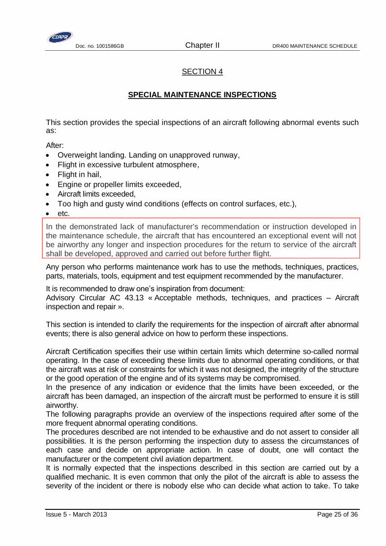
SECTION 4
SPECIAL MAINTENANCE INSPECTIONS
This section provides the special inspections of an aircraft following abnormal events such as:
After:
Overweight landing. Landing on unapproved runway,
Flight in excessive turbulent atmosphere,
Flight in hail,
Engine or propeller limits exceeded,
Aircraft limits exceeded,
Too high and gusty wind conditions (effects on control surfaces, etc.),
etc.
In the demonstrated lack of manufacturer's recommendation or instruction developed in the maintenance schedule, the aircraft that has encountered an exceptional event will not be airworthy any longer and inspection procedures for the return to service of the aircraft shall be developed, approved and carried out before further flight.
Any person who performs maintenance work has to use the methods, techniques, practices, parts, materials, tools, equipment and test equipment recommended by the manufacturer.
It is recommended to draw one’s inspiration from document: Advisory Circular AC 43.13 « Acceptable methods, techniques, and practices – Aircraft inspection and repair ». This section is intended to clarify the requirements for the inspection of aircraft after abnormal events; there is also general advice on how to perform these inspections. Aircraft Certification specifies their use within certain limits which determine so-called normal operating. In the case of exceeding these limits due to abnormal operating conditions, or that the aircraft was at risk or constraints for which it was not designed, the integrity of the structure or the good operation of the engine and of its systems may be compromised. In the presence of any indication or evidence that the limits have been exceeded, or the aircraft has been damaged, an inspection of the aircraft must be performed to ensure it is still airworthy. The following paragraphs provide an overview of the inspections required after some of the more frequent abnormal operating conditions. The procedures described are not intended to be exhaustive and do not assert to consider all possibilities. It is the person performing the inspection duty to assess the circumstances of each case and decide on appropriate action. In case of doubt, one will contact the manufacturer or the competent civil aviation department. It is normally expected that the inspections described in this section are carried out by a qualified mechanic. It is even common that only the pilot of the aircraft is able to assess the severity of the incident or there is nobody else who can decide what action to take. To take
Doc. no. 1001586GB Chapter II DR400 MAINTENANCE SCHEDULE
Page 26 of 36 Issue 5 - March 2013
into account situations where the services of a mechanic are not available, it is recommended that the following procedure be applied. Abnormal operating conditions, including, without limitation, those described in this section, must absolutely be recorded in the log book. Wherever possible, the registration should give an idea of the seriousness of the incident. An inspection of the aircraft will then have to be performed before the next flight; it will preferably be carried out by a mechanic with the appropriate qualifications. If it is impossible to obtain the services of a mechanic, the pilot of the aircraft will perform the inspection. In this case, the inspection will necessarily be limited to areas which are not subject to the issuance of a certificate for return to service after maintenance, that is to say, the inspection does not require disassembly of parts. If the pilot feels that the aircraft is in a satisfactory condition for the intended flight, it shall make an entry to that effect in the logbook, so a full inspection takes place upon return of the aircraft. The pilot will then take the planned flight or the flight segments until it reaches the facility where the remaining steps of the inspection can be made. No special flight permit is required in the circumstances. On the first occasion, the mechanic, with appropriate qualifications, shall inspect and approve the aircraft for return to service. If, to the opinion of the pilot, the aircraft is not airworthy, or if the severity of the incident is such that its airworthiness is questionable, even after a satisfactory preliminary inspection, the aircraft shall then be inspected by a mechanic who will sign the approval for return to service after the inspection, so that the airplane can resume its flight. In the following paragraphs, no distinction is made between actions that may be part of the preliminary inspection by the pilot and the actions taken by the mechanic. If there is any doubt as to the airworthiness of the aircraft, take off will not be allowed before the mechanic has signed approval for return to service after maintenance. Hard or overweight landing.
The landing gear of an aircraft is designed to withstand the impact of landing within certain weight limits and at a given rate of descent. Exceeding one or the other of these parameters during a landing will almost certainly damage the landing gear or its supporting structure. Landing gear may also suffer excessive stress when the airplane lands drifting, so that the front or tail wheel touches the runway before the main landing gear for example. However, if it is known or suspected that there was a hard landing, consult the flight crew to determine the landing conditions and whether the pilot heard noise characteristics of a structural damage. Damage caused by a hard landing primarily affects the landing gear and its supporting structure in the wing or fuselage, as well as the wing-to-fuselage connection points, the engine mount and attachment. Secondary damage can occur to the structure and the upper and lower surfaces of the fuselage, as well as the structure and wing skin, depending on the configuration and load of the aircraft. Because of the many factors involved, it would be impossible to give detailed instructions on how to perform the inspection, it varies depending on the type of incident and the aircraft type. However, preliminary inspection made after the incident should normally cover the following points:
Landing gear Remove the fairings. Check tires for creeping on wheel, flat, bumps, cuts, loss of pressure and any abnormal
dilation
Doc. no. 1001586GB Chapter II DR400 MAINTENANCE SCHEDULE
Issue 5 - March 2013 Page 27 of 36
Check the wheels and brakes for leaks, cracks or other damage; Inspect axles and torque links to check if they are bent or damaged; Check oleo struts for leaks and other; Detailed inspection of the undercarriage attachment and of adjacent structures by
looking for cracks or other damage and checking for play; this inspection may require removal of critical fastening bolts to allow to perform meticulous non-destructive testing;
Inspect structural elements adjacent to the attachment points of the undercarriage, looking for cracks, deformations, rivets or bolts showing play;
Inspect access doors and fairings to check if they are damaged or distorted; Jack airplane; have the nose wheel steering mechanism operate. Make sure of the easy sliding of the gear shock strut (after deflation, put a hose on the
valve not to lose hydraulic fluid).
Wings, fuselage Inspect extrados and intrados wing skin for damages; Search for traces of seepage or leakage of fuel at the wing tanks; Inspect the wing-to-fuselage junction fairings for cracks and signs of having moved; Make sure that the flight controls move freely and with full deflection; Inspect the balancing weights, the support of flight servo-unit; look for cracks on the
brackets and joints of the control surfaces and make sure that the control surfaces are free of damage and they do not jam in operation;
Inspect the fuselage skin for wrinkling or other damage; Make sure that emergency devices are not activated (Emergency Locator Transmitter); Check for deformation of pipes and ducts, or if they are leaking;
Engine Make sure that the engine and propeller controls move freely and with full travel; Inspect the engine mount and supports and make sure they are not damaged nor
distorted; check the tubular frames ensuring that they are not bent nor show cracked welds; check attachment bolts for damage or play;
Make sure rotary assemblies move fully free. Sparking plugs must be removed to make sure that propeller and inner parts of the engine rotate or move freely;
Inspect engine cowlings for wrinkling or distortion and make sure fasteners are in good condition;
Check for evidence of oil leakage, fuel leakage or hydraulic fluid leakage ; Inspect the battery support and attachments; Check proper alignment of the propeller shaft.
Tail assembly Make sure control surfaces move freely; Look for cracks in the joints of the rudder and stabilator; inspect the control surfaces for
cracks and distortion, particularly around the balance weight supports; Inspect the attachment points and fairings of the stabilizer, as well as the trim system
and its supports; make sure there is neither distortion nor play.
Structure - Skin Check the surface of the wing at the spar (integrity of trailing edge at wing rib no. 8
when moving the wing tip, signs of broken sticks, peeling of plywood, torn rib lacing knots etc.).
Inspection of the attachment of the stabilator bearings (peening, bruising of wood).
Doc. no. 1001586GB Chapter II DR400 MAINTENANCE SCHEDULE
Page 28 of 36 Issue 5 - March 2013
Propeller Inspect spinner and blades ends for shocks
Ground runs If the inspection has revealed no major structural deformation, then a ground run can be performed to make sure all systems and controls are working properly. It will include a general check for leaks, engines running. Flight through severe turbulence
Damage that can occur to an aircraft flying through turbulence are of the same type as the damage caused by a hard landing, except that they will be more evenly distributed and that the landing gear, wheels and brakes are likely to remain intact . During a flight in such conditions, the aircraft structure is subjected to sudden acceleration or transverse vertical, the effects of these can be multiplied by the inertia of the heavy components such as engines, fuel tanks. We can then expect that damage occurs to the main attachment points, including wing-to-fuselage or tail-to-fuselage attachments, as well as engine-to-cell attachment. Damage can also occur in parts of the wings, of the fuselage, of the stabilizer or of the control surfaces where the bending moment is at maximum, roughly half length thereof; deformation thus caused will result in wrinkle coating or cause other damage of this kind. The inspection performed after a flight turbulence report should include the "hard or overweight landing" inspections except, in most cases, the steps involved in the inspection of the landing gear. In all cases:
- Detailed inspection of the engine mount attachments - Visual inspection of all control surfaces, of their bearings and control levers. - Check the free movement of flight controls throughout their operating range. - Make sure of the proper sliding of the canopy (condition of rails).
Further dismantling and, in some cases, removal of parts of the coating may be necessary to permit inspection of the support structure in areas where there has been damage to the coating
Speed limits or load factor exceeded
In cases where it is reported that the aircraft has exceeded its approved speed limits or load factor, the inspection required is the same as that specified for a flight through severe turbulence. In cases where the exceeded limit applies to a given configuration, e.g. lowering limits of the flaps, the required inspection may then be limited to areas of the cell that were affected.
Incidents related to a burst tire If a tire burst during taxiing, takeoff or landing, fragments of the tire can damage parts of the aircraft which are in line with the wheel disc. Damage may also occur due to the fact that the wheel rolls on a paved runway and it transmits shocks to the leg of the landing gear and its supporting structure.

Doc. no. 1001586GB Chapter II DR400 MAINTENANCE SCHEDULE
Issue 5 - March 2013 Page 29 of 36
In most cases, the wheel concerned will be repaired or put out of operation. In addition, the following checks should be performed: Inspect the other wheels, the tire of which did not burst ; Inspect the brakes of the landing gear involved and look for signs of damage. The
cause of the burst can be overheating brakes that were not loose enough; it will then be necessary, when replacing the wheel, to pay a special attention to the condition of operation of the brakes, especially in regard to the frictionless rotation of the wheel, once the brakes are released;
examine the leg of the landing gear in question, including pipes and hydraulic hoses, looking for signs of damage or leaks of hydraulic fluid;
Inspect the supporting structure and the attachment points of the leg of the landing gear, looking for cracks, warped panels or loose rivets. In some cases, it may be required to remove some critical resistant structural support bolts in order to proceed to non-destructive testing;
Inspect the adjacent parts of the wing skin or of the fuselage for evidence of damage.
Strong wind or jet blast
Aircraft parked can be significantly damaged by strong wind or by the blast produced by a jet or propeller of other aircraft taxiing or performing a ground run in the vicinity. Small aircraft are particularly vulnerable to this type of damage that may be caused by the blast itself or by thrown debris. Following such incidents, inspect the aircraft as follows: Check control surfaces for deformation or other signs of internal damage. Control surface deflections; Flight Controls: make sure of the free movement of controls, inspect the cables at
pulleys level, check stops, inspect joints (lever and bell crank). Check whole cell, including windshields, for impact damage such as chips and marks,
and check if the engine air inlets, cooling ducts, etc. contain debris; If the blast was strong enough to move the entire plane, the need to conduct an internal
inspection to discover structural elements damaged, or a verification of symmetry of the whole aircraft, or both must be considered.
Landing gear: inspect the landing gear struts for deformation, crack initiation. Check the condition of axles. Inspect landing gear attachments to the fuselage and the wing. Check the condition of tires.
Bad fuelling
This kind of incident includes refueling with contaminated fuel. When it is realized that an aircraft tanks were filled with contaminated fuel or with fuel a degree inadequate, it must be determined if the fuel has already reached the engine. If by chance the problem is detected before the fuel reached the running engine, it is enough to drain all the fuel with care. To this end, the aircraft (or tanks concerned) will be emptied of all the fuel, making sure that the tanks are arranged so that the drain outlet is located at their lowest point. After draining and once the tanks are filled with clean fuel, finally supply lines must be cleaned and the engine operation checked by performing a ground runs. If the engines were supplied with polluted fuel, applicable corrective actions depend on the type of engine and type of pollution. One must refer to the maintenance manual and the

Doc. no. 1001586GB Chapter II DR400 MAINTENANCE SCHEDULE
Page 30 of 36 Issue 5 - March 2013
certification of the type of engine concerned or to the data sheets of the type certificate for additional details.
Significant change in climatic conditions
Check the tension of the flight control cables at each significant change of climatic conditions (temperatures).
Salty or tropical atmosphere
Close inspection for corrosion of all metal part every year.
Shock on propeller
Refer to AD 2004-10-14. Refer to propeller manufacturer document.
Impact on the leading edge of the wing
Damage to the wings of aircraft made of wood and fabric very often require repair. It was noted that further damage outside the impact area exposed, could often be caused to the structure of the wings. Therefore, in the context of flight safety, when a shock on the leading edge of the wings causes damage requiring repair, it is recommended to completely remove covering of the wing affected by the incident. This covering removal should allow a thorough inspection of the wooden structure and glued joints to make sure of the integrity of the wings before a return to service of the aircraft. Depending on how important is the shock, the wing main spar deforms to the rear in a flexion / torsion in the horizontal plane which can cause secondary cracks sometimes appearing at a certain distance from the main damage. If the spar exceeds the elastic limit, following the impact, the damage is transmitted to the spar itself. Cracks are formed in the grain direction of the plywood coating at the extrados and/or extrados (45 °) and more rarely against the direction of the fibers at the splice scarf joints of the plywood. Unsticking between the spar caps and the upper and lower surface coatings may also occur. In the case of an impact on the leading edge of an aircraft wing with a dihedral (aircraft type: Jodel, DR ...) a visual inspection allows, firstly, to measure the deformations at the dihedral rib tail by inspecting the lower and upper fabric at this level. If internal failure, the fabric relaxes with the deformation of the ribs rods.
Repair: Any repairs that would not have been already approved must be the subject of a record of repair submitted to EASA for approval.

Doc. no. 1001586GB Chapter II DR400 MAINTENANCE SCHEDULE
Issue 5 - March 2013 Page 31 of 36
SECTION 5
CONTROL FLIGHT
Control flights must be carried out at the end of the achievement of certain maintenance operations; the cases of current liability and the methods of their execution are defined below.
1. Case of liability
1.1. Complete control flight (see paragraphs 3 & 4)
A complete control flight consists of:
checking aircraft general performance as laid out in flight manual (take-off, climbing, and bearing) and the correct operation of various systems.
And,
carrying out procedures which do not usually apply to flight operations (especially emergency procedures).
A complete control flight shall be carried out:
after a 2000 h / 6 year inspection,
or
after major repairs following an accident unless an exemption was obtained when approval of the repair.
1.2. Abbreviated control flight
An abbreviated control flight only consists of checking some aircraft system functions that are directly or indirectly related to the work carried out.
An abbreviated control flight must be carried out when, at the completion of a maintenance operation, a ground test is not sufficient to make sure the airplane is operating correctly, specially:
after an intervention on the flight controls, except exemption after demonstration, planned in the maintenance schedule accepted by the qualified services, or

Doc. no. 1001586GB Chapter II DR400 MAINTENANCE SCHEDULE
Page 32 of 36 Issue 5 - March 2013
after replacement or reinstallation (*) of the engine (except for single engine fitted with fixed pitch propeller. An exemption can however be obtained from the qualified services, for the aircraft maintained within an approved framework, when it was shown by at least two consecutive control flights that the operations of replacement or reinstallation were carried out in a fully satisfactory way; the demonstration of reinstallation is worth only for the reinstallation; no exemption can be granted for a replacement relating to more half of the engines installed; or
when, after a design change or a repair of the aircraft, the need to carry out a control flight is stated in the design change file or approved repair file or
for the radio installations, after a maintenance inspection which required demounting and the bench test of the equipment, or after a routine inspection by the method known as of “global test”.
(*) Replacement is the removal of an engine followed by the installation of another engine, and reinstallation is the removal and reinstallation of an engine to its original position without any major intervention (such as the replacement of module) being carried out on this engine.
2. Remarks
At each control flight, check the carbon monoxide CO ratio during climb and during cruise. The CO ratio should permanently be lower than 50 ppm. Use an electronic portable CO detector with 1 ppm resolution. During measurements, take the precision of the detector into consideration.

Doc. no. 1001586GB Chapter II DR400 MAINTENANCE SCHEDULE
Issue 5 - March 2013 Page 33 of 36
A. DR400/135 CDI or DR400/155CDI reception / in flight control record
CEAPR DR400/135 CDI or DR400/155 CDI reception / in flight control record
Flight data Date Model Regist. Serial nr Location Pilot Mass / C QFE ZP Temp. Wind
Fuel on board Left hand Main Right hand Sup. LH Sup. Rear Sup. RH Total
Flight time Dep. Park. Take off Landing Ret. Park. Time Total
Flight 1
Flight 2
Flight 3
Engine S/N: RPM prop % power MAP P rail TH2O T oil P oil T gear Fuel flow T ecu A T ecu B
After start-up
Take-off
Climb FL 30
Climb FL 60
Cruise full throttle FL 50
Cruise 72% FL 50
Idle
Speeds Stall Cruise High speed
Trim mini Warning Stall PG 72% Adjustments VFE VNE OBS
VS 1 Vi = Vi = Ball Ailerons
VS 0 T° = T° = RPM:
Accessories and equipment
Painting aspect Fuselage Elevat. Rudder RH Flap RH
Aileron RH wing Cowlings Spinner LH wing LH Flap LH Aileron
Lights Nav lights Strobe Taxi light Ldg light
Flight controls Ailerons Elevator Rudder Elev. Tab Rud. Tab PA
Engine controls Throttle Mixture Carbu Propeller Friction Alt Air Cut. Mag Cut. Rich
Engine Instruments Oil Pr. Oil T° Cyl. T° Carb. T° EGT PA FF fuel Pres RPM Amp. Volt.
Brakes and gears LH Brake RH Brake Park. Straight ahead Steering Gnd Clear. Fonc. TR Sec. TR
Electric power supply Charge Voltage Breakers Regul. Alternat.
Instrument panel Painting Placards Markings Inst. Light Cab. Light Light test Shock m. Hourmeter Suction
Flight instruments Air speed Alti 1. Alti. 2 Vert. speed Ball ind. Horiz. 1 Horiz. 2 Dir.Gyro HSI Inst. Pan. Ind Compass
Avionic VHF 1 VHF 2 VOR 1 VOR 2 ATC MKR DME GPS ADF ILS
Listening Loud Speak Mike 1 Mike 2 Headph. 1 Headph. 2 Intercom ELT
Fuel LH gauge Pres. Sens. RH gauge Aux. LH Aux Rear Aux. RH Select LP warn LL warn
Seats Harnesses Belts Adjust. Fasten.
Air conditioning LH air vent RH air vent Defrost. Front heat. Rear Heat.
Canopy Sliding Latch Plexi Sun shield Tightness Jettison.
REMARKS CORRECTIVE ACTIONS VISA
Visa of reception pilot after corrective actions completed:
Formulaire 087-0A
Check the carbon monoxide CO ratio during climb and during cruise. The CO ratio should permanently be lower than 50 ppm. Use a portable electronic CO detector with 1 ppm resolution. During measurements, take the precision of the detector into consideration.

Doc. no. 1001586GB Chapter II DR400 MAINTENANCE SCHEDULE
Page 34 of 36 Issue 5 - March 2013
4. Complete control flight program – Lycoming engine
C.E.A.P.R.
Flight data Date Model Regist. Serial nr Location Pilot Mass / C QFE ZP Temp. Wind
Fuel on
board Left hand Main Right hand Supp. Rear Total
Flight time Dep. Park. Take off Landing Ret. Park. Time
Flight 1
Flight 2
Flight 3
Moteur Oil pres. Oil Temp. Cyl. Temp. Carb. Temp. Fuel Pres. RPM
Manifold
Pres. Fuel Flow Carb. Heat Mag. 1 Mag. 2
After start-up
Run up
1800 rpm
Take off
Climb
Cruise full
throttle
Cruise 75%
Idle
Speeds
Trim mini Warning Stall PG 75% VFE VNE OBS
VS 1 Ball Ailerons
VS 0 RPM:
Painting aspect Fuselage Elevator Rudder RH flap RH aileron RH wing Cowlings Spinner LH wing LH flap LH aileron
Lights Nav lights Strobe Taxi light Landing light
Flight controls Ailerons Elevator Rudder Elevator tab Rudder tab PA
Engine controls Throttle Mixture Carbu Propeller Friction Alt. air Cut. Mag Cut. Mixture
Engine instruments Oil pres. Oil Temp. Cyl. Temp Carb. Temp. EGT PA FF Fuel Pres. RPM Amp. Volt.
Brakes and gears LH Brake RH Brake Park. Straight ahead Steering Gnd Clear.
Electric
power supplyCharge Voltage Breakers Régul. Alternat.
Instrument
panelPainting Placards Markings Inst. Light Cab. Light Light test Shock m. Hourmeter Suction
Flight
instrumentsAir speed Alti 1. Alti. 2 Vert. Speed Ball indic. Horiz. 1 Horiz. 2 Dir. Gyro HSI
Turn & bank
indic.Compass
Avionics VHF 1 VHF 2 VOR 1 VOR 2 ATC MKR DME GPS ADF ILS
Listening Loud speaker Mike 1 Mike 2 Headset 1 Headset 2 Intercom ELT
Fuel LH gauge Press. Sens. RH gauge Aux. rear Select LP Alarm LL Alarm
Seats Harnesses Belts Adjust. Latch.
Air conditioning LH air vent RH air vent Defrost. Front heat. Rear heat.
Canopy Sliding Latch Plexi Tightness Jettison.
VISA
Reception / in flight control record
DR 400 - Lycoming
Temps de vol total
Stall Cruise High speed
Adjustments
Accessories and equipment
REMARKS CORRECTIVE ACTIONS
Formulaire 087-0B
Visa of reception pilot after corrective
actions completed: Check the carbon monoxide CO ratio during climb and during cruise. The CO ratio should permanently be lower than 50 ppm. Use a portable electronic CO detector with 1 ppm resolution. During measurements, take the precision of the detector into consideration.

Doc. no. 1001586GB Chapter II DR400 MAINTENANCE SCHEDULE
Issue 5 - March 2013 Amendment 7 dated April 2015 Page 35 of 36
SECTION 6
MAINTENANCE OPERATIONS TABLE
Following notes are related to right hand column of the maintenance operations table. Note 1: Refer to Lycoming documentation (operator’s manual, SB, SL SI…).
Note 2: Dusty conditions: cleaning of the filter element every 25 flight hours.
Note 3: Refer to the relevant maintenance manual issued by the manufacturer of the magneto.
Note 4: If the aircraft is equipped with a carbon detector (stuck inside the cabin), the removal of the exchanger will occur every 500 hours.
Note 5: The overhaul of the starter is linked to the general overhaul of the engine: refer to the latest issue of SI n°1157 Textron-Lycoming.
Note 6: Refer to the latest issue of the propeller Owner’s manual and to instructions (refer to section 1, §F).
Note 7: Before filling the oleo strut with hydraulic fluid, check the travel of the sliding leg.
Note 8: Cleaning of the fuel filter needs to shut off the fuel cock: test its efficiency.
Note 9: The fuel cock is to be disassembled only in an approved workshop.
Note 10: Refer to the manufacturer’s documentation depending on the equipment of the aircraft.
Note 11: Alternator belt: refer to Textron-Lycoming SI n°1129.
Note 12: Refer to section “Special maintenance inspections”.
Note 13: For DR400/140B equipped with STC EASA. 10014219, refer to Operation &
Maintenance Manual TAE and/or Supplement Airplane Maintenance Manual (refer to section 1, §F).
Note 14: Not applicable to DR400/140B equipped with STC EASA. 10014219.
Note 15: Serial number > 2209
Note 16: Serial number < 2210
Note 17: Serial number < 2216
Note 18: « flûtes » Option
Note 19: Silencer « APR » Option
Note 20: Refer to SB 020602 DR400 – Elevator – Anti-tab – Inspection procedures
Note 21: Refer to SB 169 Brake fluid reservoir cap
Note 22: DR400/160 and DR400/180: model before 1988.
Note 23: Removal of wheel and gear leg fairings shall be done every 50 hours after using the airplane on grass airfield.
Note 24: Operation shall also be done when exchanging the tires.
Note 25: Concerns luggage compartment door with part number 28.18.46.010. Aircraft serial number from 2210 on.
Doc. no. 1001586GB Chapter II DR400 MAINTENANCE SCHEDULE
Page 36 of 36 Amendment 7 dated April 2015 Issue 5 - March 2013
Note 26: Refer to SB 031104. 6 years or at least before the end of the engine life limit, whichever comes first.
Note 27: Refer to mandatory Service bulletin Lycoming no. 480 at latest issue.
Note 28: Refer to mandatory Service bulletin 120205
Note 29: In the event of significant use on surface coated, dusty or degraded (area start-up,
fixed point, taxiiage, take-off and landing in grass, sand, dirt or any surface in hard not maintained), the operation is to be carried out every 50 h.
Note 30: Only for aircraft fitted with electrical rudder trim P/N 32.18.00.000 (mounted on aircraft
after 1992). For other electrical rudder trim, the operation is to be carried out every 50 h.
Maintenance operation table
The maintenance operation table is the subject of the following annex.
Models concerned X: applicable O: option

Doc. 1001586GB ANNEX
MAINTENANCE OPERATIONS TABLE
DR 400 Maintenance schedule
Sec Rep
120
140B
160
180
180R
200R
500
TASKS 50 100 500 1000 2000 1 3 6
Notes
Remarks
Manuals references
21 0 X X X X X X X HEATING AND VENTILATINGl l l l l l l l
ME1001606, sec13
ME1001606, sec16, §16-10
21 10 X X X X X X XHeating: Check tightness of heating installation,
especially in the vicinity of heat exchangerl l l l l l l l 13
21 20 X X X X X X XCheck flexible ducts and clamps. Check
attachment byside engine controlsl l l l l l l 13
21 30 X X X X X X XClose examination of the hot air distribution box,
flexible controls. Test for good operating.l l l l l l
21 40 X X X X X X X
Ventilation: Check state of flexible ducts,
proofness of duct and plastic inlet bonded along
fuselage aft sides. Test of aerators.
l l l l l
21 50 X X X X X X XCheck cleanliness of lateral intake vent holes
and cabin air ventsl l l l l l l
21 60 X X X X X X X
Rear passengers ventilation: removal of the
aerators and close examination of the expansion
box (moisture, rotten areas, lack of protective
paint, etc.).
l l l l
21 70 X
Close examination of flexible ducts of the rear
passenger ventilation: from the fin root air inlet to
the expansion box located under the fuselage
arm-rest.
l l l l l l l
l l X X X X X X X l l l l l l l l l l
23 0 X X X X X X X RADIO-NAV EQUIPMENTl l l l
l l l10
ME1001606, sec15
23 10 X X X X X X XClose examination of antennas, bases and fixing
elements.l l l l l
23 20 X X X X X X X
Inspection of each coax-cable on all the length,
particularly when crossing bulkheads and
attachments.
l l l l l
23 30 X X X X X X XDetailed examination of radio racks and fixing
(search for cracks etc.).l l
23 40 X X X X X X XTest of Emergency Locator Transmitter. Check
attachments.l l l l l l l
l l X X X X X X X l l l l l l l l l l
24 0 X X X X X X X ELECTRICAL POWERl l l l l l l l
ME1001606, sec12
ME1001606, sec16, §16-9
24 10 X X X X X
Battery: detailed inspection of the battery in
order to detect possible leaks. Particularly check
around terminals.
l l l l l l l 13
24 20 X X X X X
Remove the battery and check the support
frame, the fixing area of the firewall (seek for
corrosion signs, cracks, defective fixing). Verify
the battery charge. Check electrolyte density and
level. Clean and protect the terminals with
grease.
l l l l l l l13
ME1001606, sec12, §12-1
24 30 X X
Battery: detailed inspection of the battery in
order to detect possible leaks. Particularly check
around terminals.
l l l l l l l ME1001606, sec16, §16-9
24 40 X X
Remove the battery and check the support
frame, the fixing area of the firewall (seek for
defective fixing, glue cracks…). Verify the battery
charge. Check electrolyte density and level.
Clean and protect the terminals with grease.
l l l l l l l ME1001606, sec16, §16-9
24 50 X X X X X X X
Close examination of master relay and starter
relay. Ensure that contacts are well-protected
with insulator caps. Check attachment to firewall.
l l l l ME1001606, sec12, §12-3
24 60 X X X X X X XCheck all electrical wires (burn traces, wear).
Check for efficient attachment.l l l l 13
24 70 X X X X X X X Check alternator belt tensioning. l l l l11, 13
Textron Lycoming SI 1129
Models concerned Ro
uti
ne
(ho
urs
)
Deta
iled
(ho
urs
)
Cale
nd
ar
tim
e
(years
)
Issue 5 - march 2013 Page 1 Amendment 7 April 2015

Doc. 1001586GB ANNEX
MAINTENANCE OPERATIONS TABLE
DR 400 Maintenance schedule
Sec Rep
120
140B
160
180
180R
200R
500
TASKS 50 100 500 1000 2000 1 3 6
Notes
Remarks
Manuals references
Models concerned Ro
uti
ne
(ho
urs
)
Deta
iled
(ho
urs
)
Cale
nd
ar
tim
e
(years
)
24 80 X X X X X X XRemoval of the alternator. Check ball bearings,
brushes, collector, attachments, diodes.l l l 13
24 90 X X X X X X X
Into cabin and fuselage
Detailed inspection of electrical wires over
complete length (behind instrument panel,
behind upholsteries, inside the fuselage…),
removing parts to allow access.
l l l
24 100 X X X X X X X Verify the good operating of cabin lights. l l l l l l l
24 110 X X X X X X X
Verify the good operating of wingtip
position/strobe lights, landing and taxi lights,
anticollision lights, rotating beacon. Check
glasses and fixing elements.
l l l l l l l
24 120 X X X X X X X Check presence of spare fuses. l l l l l l l 14
24 130 X X X X X X X
Check for good operating conditions the voltage
regulator and the charge drop warning light. l l l l 13
l l X X X X X X X l l l l l l l l l l
25 0 X X X X X X X SEATS l l l l l l l l ME1001606, sec14
25 10 X X X X X X XCheck sliding of each seat and locking
mechanism.l l l l
25 20 X X X X X X X Grease the locking mechanism. l l l l l l l
25 30 X X X X X X XDetailed examination of the fixing elements (seat
on structure).l l l l
25 40 X X X X X X XBending test of the back of the front seats in
order to point out possible cracks.l l l l
25 50 X X X X X X XRemoval of bottom cushion and visual
inspection of frame tubes for cracks.l l l
25 60 X X X X X X X
Seat belts or harnesses:
Close inspection of belts or harnesses. Check
anchor bolts.
l l l l l l l
25 70 X X X X X X X Check buckles for good operating. l l l l
25 80 X X X X X X X Test of the inertia reel safety belts operating. l l l l l l l
25 90 X X X X X X X
Upholsteries: check state of upholsteries,
attachments, particularly in rudder bar travel
area as well as in the seat slide control
mechanism.
l l l l l l
l l X X X X X X X l l l l l l l l l l
27 0 X X X X X X X FLIGHT CONTROLS l l l l l l l l ME1001606, sec6
27 10 X X X X X X XCheck all flight controls for free operating from
stop to stop (stabilator, rudder, ailerons)l l l l l l l
27 20 X X X X X X XEnsure that there is no abnormal play in the
controls.l l l l
27 30 X X X X X X X
Check the good operating of the elevator trim
control from block to block when stick is full nose
down and full nose up.
l l l l
27 40 X X X X X X XIndex guide tube: look for friction points and
marks of perforation in the elbowsl l l
27 50 X X X X X X X Verification of the control cable tensioning. l l l l l l l12
ME1001606, sec6, §6-1
27 60 X X X X X X XVisual inspection of pulleys, supports, cable
guides.l l l
27 70 X X X X X X X
Release the tension of cables and check them
for wear at each contact zone (pulleys, guides):
no damage acceptable. Visual examination of
the pulleys, test of rolling.
l l l l lFlight safety
sensitive !
27 80 X X X X X X XRemoval of all cables and check over complete
length: no damage acceptable.l l
Flight safety
sensitive !
27 90 X X X X X X X
Visual inspection of rudder bars, bearings, dual
control column sticks, dual control rods,. Check
the good condition of rod end bearings and axles
(crack, corrosion).
l l l l l
27 100 X X X X X X X
Removal of rudder pedals to check fixing axis of
rudder cables and of front wheel guide (link rod).
Replacement of the fixing screws of the rudder
pedals bearings.
l lFlight safety
sensitive !
Issue 5 - march 2013 Page 2 Amendment 7 April 2015

Doc. 1001586GB ANNEX
MAINTENANCE OPERATIONS TABLE
DR 400 Maintenance schedule
Sec Rep
120
140B
160
180
180R
200R
500
TASKS 50 100 500 1000 2000 1 3 6
Notes
Remarks
Manuals references
Models concerned Ro
uti
ne
(ho
urs
)
Deta
iled
(ho
urs
)
Cale
nd
ar
tim
e
(years
)
27 110 X X X X X X X
Mechanical control: Detailed examination of the
elevator trim mechanism including control gear
box, control flexible shaft, rigid sleeve. State of
slides, axles, attachment parts, spherical joint of
the deflection control system.
Electrical control: visual inspection of system,
check good condition of axles and actuator
cylinder. Visual inspection of attachment parts
and pyramid structure, actuator's attachment
points.
l l l l l
Ref & MM
Flight safety
sensitive !
27 120 X X X X X X X
Detailed examination of the flap root rib. Make
sure the fastening rivets of the rib (equipped with
floating anchor nuts) are in good condition.
l l20
BS 020602
27 130 X X X X X X X
Inside the cabin, remove the plastic beautifier in
order to carry out a detailed inspection of the flap
control mechanism. Condition of axles, safety-
pins, no crack, no wear on the “lock-in position”
aluminium plate.
Electrical control: visual inspection of system,
check good condition of axles and actuator
cylinder.
l l l l l l lFlight safety
sensitive !
27 140 X X X X X X X
Detailed examination of the control rod located
under the wings. State of bearings, swagings
corrosion, wear.
l l l l l l lFlight safety
sensitive !
27 150 O O O O O O OCheck the cable for good rolling-up when the
rudder trim is operatingl l l l l l l 30
27 160 O O O O O O O
Rudder trim. Check the route of the cables
around the pulleys. State of pulleys, axles,
presence of the safety screws (preventing
cables from sliping out of the pulleys).
l l l l l l l
27 170 O O O O O O OAutopilot. Check state of the servo: fixings, servo
cable to control cable attachment.l l l l l l l
27 180 X
After removal of the central fairing and cabin
protection, close examination of the flaps control.
State of axles, presence and efficiency of the
safety pins. Good operating of the electro-
mechanical control. Check of attachments.
l l l lFlight safety
sensitive !
27 190 O O O O O O OAutopilot. Verification, adjustment of the friction
clutch of the servosl l
Flight safety
sensitive !
l l X X X X X X X l l l l l l l l l l
31 0 X X X X X X X AIRSPEED CIRCUIT l l l l l l l l ME1001606, sec10
31 10 X X X X X X X Cleanliness of the pitot and static pressure linel l l l l l l
29
31 20 X X X X X X X
Inspection of the static line (route, fixings,
crushing). ll
l l l l l
31 30 X X X X X X X
Check state of the pitot line, fixings and tubes
fitting. l
l
l l l l l
31 40 X X X X X X X Detailed inspection of fixings and dampers l l l
l l X X X X X X X l l l l l l l l l l
32 0 X X X X X X X LANDING GEARS l l l l l l l l ME1001606, sec7
32 10 X X X X X X X
Remove the wheel fairings and leg fairings and
check them for good state. Visual inspection of
the sliding leg (search for leaks, traces of
corrosion, nicks, wear areas…).
l l l l l l l 23
32 20 X X X X X X X
Visual examination of the fixed strut (look for
cracks, corrosion), of the torque links, axles and
plastic bushes of the torque links.
l l l l l l
32 30 X X X X X X X
Check of the play in the bushings of the
compass (nose landing gear & main landing
gear)
l l l l l l
32 40 X X X X X X XFill-in and check of the hydraulic fluid level of the
oleo-strut.l l l l 7
Issue 5 - march 2013 Page 3 Amendment 7 April 2015

Doc. 1001586GB ANNEX
MAINTENANCE OPERATIONS TABLE
DR 400 Maintenance schedule
Sec Rep
120
140B
160
180
180R
200R
500
TASKS 50 100 500 1000 2000 1 3 6
Notes
Remarks
Manuals references
Models concerned Ro
uti
ne
(ho
urs
)
Deta
iled
(ho
urs
)
Cale
nd
ar
tim
e
(years
)
32 50 X X X X X X X Inflate tires. l l l l l l l l
32 55 X X X X X X X Inflate oleo-strut. l l
32 60 X X X X X X XRemoval of the sliding leg. Dye penetrant test of
the axle-to-leg weldings. Replace O-rings.l l
32 70 X X X X X X X
Main landing gears
visual inspection of the main landing gear
attachment bolts.
l l l l ME1001606, sec7, §7-3
32 80 X X X X X X X
Main landing gears
Remove the main landing gear. Dye penetrant
test of struts and links after external chemical
cleaning.
l l ME1001606, sec7, §7-3
32 90 X X X X X X X
Main landing gears
Detailed examination of the main landing gear
housing, of the fixing bolts and structures round
about.
l l ME1001606, sec7, §7-3
32 100 X X X X X X X
Nose landing gear
Check the support frame and the friction
moment of the anti-shimmy device.
Replacement of the anti-shimmy washer when
friction moment not achieved. Ensure that main
axle, two axle bearings, nut and lock washer are
in good operating condition.
l l l l ME1001606, sec7, §7-2-13
32 110 X X X X X X X
Nose landing gear
Detailed inspection of the centering control
mechanism: attachment of the bar, adjustment
of the cam operating point; chack cam and latch
for wear.
l l l l ME1001606, sec7, §7-2
32 120 X X X X X X X
Nose landing gear
Check steering rods (state of rod ends, wear of
rod bulkhead).
l l l l l l l ME1001606, sec7, §7-2
32 130 X X X X X X X
Nose landing gear
Remove the nose landing gear. Dye penetrant
test of the strut, supporting plates and links after
external chemical cleaning.
l l ME1001606, sec7, §7-2
32 140 X X X X X X X
Nose landing gear
Visual inspection of the supporting plate
(between strut and main axle): seek for cracks
around the welding areas.
l l l l l l l ME1001606, sec7, §7-2
32 150 X X X X X X XWheels:
check tires for possible cuts and defectsl l l l l ME1001606, sec7, §7-4
32 160 X X X X X X XWheels
Visual check of wheel hub for cracksl l l l ME1001606, sec7, §7-4
32 170 X X X X X X X
Wheels
Check marking to make sure that the tire is not
slipping
l l l l l ME1001606, sec7, §7-4
32 180 X X X X X X XWheels
Check state of bearings (manually or by ear)l l l l l l l ME1001606, sec7, §7-4
32 190 X X X X X X X
Wheels : Remove wheels. Check state of ball
bearings and inner and outer seating faces.
Lubricate ball bearings.
l l l l l24
ME1001606, sec7, §7-4
32 200 X X X X X X X Wheels : Check inner tube and valve (wear) l l l24
ME1001606, sec7, §7-4
32 210 X X X X X X X Brake system: check brake disk and linings l l l l l l l ME1001606, sec8
32 220 X X X X X X XBrake system: check brake fluid reservoir (level,
vent holes, leaks).l l l l l l l
21
BS 169
ME1001606, sec8
32 230 X X X X X X X
Brake system: Close inspection of the complete
brake circuits from wheel to hydraulic fluid
reservoir (seek for leaks from fittings, abnormal
wear of piping..).
l l l l ME1001606, sec8
32 240 X X X X X X X
Brake system: Make sure that master cylinder
and parking valve are correctly operating
(efficiency).
l l l l l l l ME1001606, sec8
32 250 X X X X X X XBrake system: Drain the brake circuit. Replace
hydraulic brake fluid. Bleed the brake circuit.l l ME1001606, sec8
l l X X X X X X X l l l l l l l l l l
Issue 5 - march 2013 Page 4 Amendment 7 April 2015

Doc. 1001586GB ANNEX
MAINTENANCE OPERATIONS TABLE
DR 400 Maintenance schedule
Sec Rep
120
140B
160
180
180R
200R
500
TASKS 50 100 500 1000 2000 1 3 6
Notes
Remarks
Manuals references
Models concerned Ro
uti
ne
(ho
urs
)
Deta
iled
(ho
urs
)
Cale
nd
ar
tim
e
(years
)
37 0 X X X X X X X VACUUM SYSTEM l l l l l l ME1001606, sec10
37 10 X X X X X X X
Visual inspection of hoses, engine side and
cabin side. ll
l l l l
37 20 X X X X X X X
Detailed inspection of the dry air vacuum pump,
attachments, fittings, vents. l l l l l13
l l X X X X X X X l l l l l l l l l l
53 0 X X X X X X X FUSELAGE l l l l l l l l ME1001606, sec4
53 10 X X X X X X X
Visual check of all the fuselage covering. Seek
for crushing, cracks, distorsion, peeled off
painting…
l l l l l l l
53 20 X X X X X X X
Detailed inspection of the fuselage cover. Close
examination of internal fuselage structure (seek
for rooted away areas, stringer gluing…).
l l l l l l l
53 30 X X X X X X XDetailed examination of the firewall bulkhead,
particularly around the battery area.l l l l l l l l 13, 14
53 40 X X X X X X X
Visual inspection of the cabin wooden floor after
removal of the carpet and upholsteries. Cleaning
of floor, carpet and upholsteries.
l l l l l l
53 50 X X X X X X XDetailed examination of the central airframe
section (wing attachment) and fixing bolts.l l l l
53 60 X X X X X X X Make sure that water drain holes are free. l l l l l l
53 70 X X X X X X X
Look for glue cracks, crushing, all over the rear
part of the fuselage. Check the tail skid shoe and
its fixing bolts.
l l l l l l l
53 80 X X X X X X X
Close examination of the rectangular section
structural bars holding the wing. Carefully check
the fixing bolts and the corresponding inside
fuselage structure
l l l l l
53 90 O O O O
Luggage compartment door (P/N 28.18.46.010)
Visual inspection of seal for tightness.
Replacement on condition.
Visual inspection of door casing adhesive on
fuselage dome.
Visual inspection of luggage compartment door
hinge and swivel fitting condition.
Check the two latch locks work properly,
possible adjustment of force.
Lubricate protect the locks.
l l l l 25
l l X X X X X X X l l l l l l l l l l
54 0 X X X X X X X POWERPLANT BRACKET l l l l l l ME1001606, sec4
54 10 X X X X X X XCheck the efficient sealing of the firewall from
the structural bulkhead (gluing, sealing).l l l l l l
54 20 X X X X X X X
Detailed inspection of the engine mount
attachment (crushing under plates, inside the
cabin).
l l l l l l
54 30 X X X X XSwivelling engine mount: state of the pivot points
(bores, corrosion,…) and bolts.l l l l l l 14
54 40 X X X X X X X
Checking and re-tightening of the fixing bolts
(crossing the firewall) with adding of a washer if
necessary.
l l l l l l
l l X X X X X X X l l l l l l l l l l
55 0 X X X X X X X CONTROL SURFACES l l l l l l l ME1001606, sec6
55 10 X X X X X X X
Overall inspection of the rudder (fabric covering,
painting, structures). Particularly check the tail
light area. Make sure there is no play between
bellcrank and structure.
l l l l l l l
55 20 X X X X X X X
Overall inspection of the horizontal stabilator
(fabric covering, painting, structures). Detailed
inspection of the sunk-in control lever zone
(crushing).
l l l l l l l
55 30 X X X X X X X
Remove the access panels, fin root fairing to
inspect the horizontal stabilator bearings and
brackets as well as the fin supporting frame.
l l l l l l l
Issue 5 - march 2013 Page 5 Amendment 7 April 2015

Doc. 1001586GB ANNEX
MAINTENANCE OPERATIONS TABLE
DR 400 Maintenance schedule
Sec Rep
120
140B
160
180
180R
200R
500
TASKS 50 100 500 1000 2000 1 3 6
Notes
Remarks
Manuals references
Models concerned Ro
uti
ne
(ho
urs
)
Deta
iled
(ho
urs
)
Cale
nd
ar
tim
e
(years
)
55 40 X X X X X X XCheck axles, bolts, bearings of the stabilator
pivot points (wear…).l l l l
55 50 X X X X X X XMake sure that blocks are in good condition
(mould, cracks, fixing…).l l
55 60 X X X X X X XCheck the gap between bolts and bearings of
the rudder pivot point.l l l
55 70 X X X X X X XCheck the hinge axles of rudder and hinge
fixation on vertical stabilizer and rudderl l l l
55 80 X X X X X X X
Remove the rudder. Close inspection of bolts
and bearings (wear). Reassemble the rudder
and check deflection angles.
l l lFlight safety
sensitive !
55 90 X X X X X X X Make sure that the drain holes are free. l l l l l l
55 100 X X X X X X X
Visual inspection of the balancing weight
supporting tube and fixing on stabilator spar
(corrosion of the tube, state of bolts).
l l l l lFlight safety
sensitive !
55 110 X X X X X X X Visual inspection of anti-tab control surfaces l l l l l l l
55 120 X X X X X X XCheck the play in anti-tab control surface piano
hinge.l l l l
55 130 X X X X X X X
Remove the anti-tab surface, check hinge and
pins (wear, corrosion). Reassemble the anti-tab
surface and check deflection.
l l l l l lFlight safety
sensitive !
55 140 X X X X X X XGrease the bearings and axles of the rudder and
stabilator pivot points.l l l l l l
l l X X X X X X X l l l l l l l l l l
56 0 X X X X X X X CANOPY l l l l l l l ME1001606, sec4
56 10 X X X X X X XCheck the locking system for good operation
and sliding guides for smooth travelling.l l l l l l l
56 20 X X X X X X XCheck glasses for good state and correct
assembly (crazing, cracks, sealing).l l l l l l l
56 30 X X X X X X X
Check the efficiency of the bonding between
glasses and frame all along the periphery
(depending on fixing mode).
l l l l l l l 15
56 40 X X X X X X
Inspection of the rivets and screws fixing the
glasses on the frame (depending on fixing
mode).
l l l l 14
56 50 X X X X X X X
Remove the sliding canopy. Check sliding
guides. Make sure the jettison system is well
operating.
l l l l l lFlight safety
sensitive !
56 60 O XCheck the adjustable rear view mirror for good
operating, fixation and sealing.l l l l l l l
l l X X X X X X X l l l l l l l l l l
57 0 X X X X X X X WINGS l l l l l l l l ME1001606, sec4
57 10 X X X X X X X
Check the state of the whole fabric covering
(cracks, rib lacing, tear…). EV of painting at
leading edge level, at spar level and between
wing tanks and main spar to make sure of no
possible ingress of water.
l l l l l l l
57 20 X X X Dismantle tanks for moisture and mold. l l
57 30 X X X X X X XCheck the ribs and the rear spar (aileron and
flaps) with slight thumb pressing.l l l l l l
57 40 X X X X X X X
Verify the state of the step area and the
protective sheet located at the trailing edge
(wear, sealing…).
l l l l l
57 50 X X X X X X X
General state of aileron control surface.
Particularly check the trailing edge strip of wood,
the fixing areas and the deflection blocks.
l l l l l l l
57 60 X X X X X X X
General state of the flaps. Look for loosen rivets,
defective hinge and good condition of the rib
where the control lever is attached.
l l l l l l l
57 70 X X X X X X XCheck condition and grease the flaps hinges and
axles of flaps control levers.l l l l l l l
57 80 X X X X X X X
Check condition and grease the axles of aileron
hinges. Check fixation of hinges to wing small
spar and aileron spar. Check aileron control
cable fork end bolts.
l l l l
Issue 5 - march 2013 Page 6 Amendment 7 April 2015
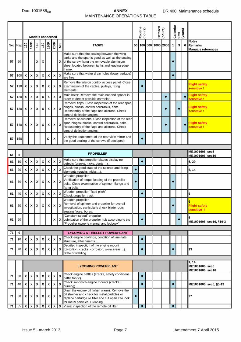
Doc. 1001586GB ANNEX
MAINTENANCE OPERATIONS TABLE
DR 400 Maintenance schedule
Sec Rep
120
140B
160
180
180R
200R
500
TASKS 50 100 500 1000 2000 1 3 6
Notes
Remarks
Manuals references
Models concerned Ro
uti
ne
(ho
urs
)
Deta
iled
(ho
urs
)
Cale
nd
ar
tim
e
(years
)
57 90 X X X
Make sure that the sealing between the wing
tanks and the spar is good as well as the sealing
of the screw fixing the removable aluminium
sheet located between tanks and leading edge
frame.
l l l
57 100 X X X X X X XMake sure that water drain holes (lower surface)
are free.l l l
57 110 X X X X X X X
Remove the aileron control access panel. Close
examination of the cables, pulleys, fixing
elements.
l l l lFlight safety
sensitive !
57 120 X X X X X X XMain bolts: Remove the main nut and spacer in
order to detect possible corrosion.l l
Flight safety
sensitive !
57 130 X X X X X X X
Removal flaps. Close inspection of the rear spar,
hinges, blocks, control bellcranks, bolts…
Reassembly of the flaps and ailerons. Check
control deflection angles.
l l lFlight safety
sensitive !
57 140 X X X X X X X
Removal of ailerons. Close inspection of the rear
spar, hinges, blocks, control bellcranks, bolts…
Reassembly of the flaps and ailerons. Check
control deflection angles.
l lFlight safety
sensitive !
57 150 O XVerify the attachment of the rear view mirror and
the good sealing of the screws (if equipped).l l l l
l l X X X X X X X l l l l l l l l l l
61 0 X X X X X X X PROPELLERl l l l l l l l
ME1001606, sec5
ME1001606, sec16
61 10 X X X X X X XMake sure that propeller blades display no
defects (cracks, nicks, dents…).l l l l 6, 29
61 20 X X X X X X XCheck the good state of the spinner and fixing
elements (cracks, nicks…).l l l l l 6, 14
61 30 X X X X X X X
Wooden propeller
Verification of torque loading of the propeller
bolts. Close examination of spinner, flange and
fixing bolts.
l l l l l l l l
61 40 X X X X X X XWooden propeller “fixed pitch”
Check propeller trackl l l l 6
61 50 X X X X X X X
Wooden propeller
Removal of spinner and propeller for overall
investigation, particularly check blade roots,
seating faces, bores.
l l l
6
Flight safety
sensitive !
61 60 X X
“Constant speed” propeller
Lubrication of the propeller hub according to the
“Propeller owner’s manual and logbook”
l l l l l l6
ME1001606, sec16, §16-3
l l X X X X X X X l l l l l l l l l l
71 0 X X X X X X X LYCOMING & THIELERT POWERPLANT l l l l l l l
71 10 X X X X X X XCheck engine cowlings, condition of laminate
structure, attachments…l l l l
71 20 X X X X X X X
Detailed inspection of the engine mount
(distortion, cracks, corrosion, worn areas…).
State of welding.
l l l l l l l 13
l l X X X X X X X l l l l l l l l l l
X X X X X X XLYCOMING POWERPLANT
l l l l l l l l
1, 14
ME1001606, sec5
ME1001606, sec16
71 30 X X X X X X XCheck engine baffles (cracks, safety conditions,
baffle fabric).l l l l
71 40 X X X X X X XCheck sandwich engine mounts (cracks,
burning). l l l l l l l ME1001606, sec5, §5-13
71 50 X X X X X X X
Drain the engine oil (when warm). Remove the
oil strainer and check for metal particles or
replace cartridge oil filter and cut open it to look
for metal particles. Cleaning.
l l l l l 27
71 55 X X X X X X X Visual inspection of the remote oil filter l l
Issue 5 - march 2013 Page 7 Amendment 7 April 2015

Doc. 1001586GB ANNEX
MAINTENANCE OPERATIONS TABLE
DR 400 Maintenance schedule
Sec Rep
120
140B
160
180
180R
200R
500
TASKS 50 100 500 1000 2000 1 3 6
Notes
Remarks
Manuals references
Models concerned Ro
uti
ne
(ho
urs
)
Deta
iled
(ho
urs
)
Cale
nd
ar
tim
e
(years
)
71 60 X X X X X X X
Inspection of oil cooler. Check for good condition
of honeycomb structure, leaks, fittings,
attachment points.
l l l l
71 70 X X X X X X X Check oil tubing. Overall state, fittings… l l l l l l l
71 80 X X X X X X XClose examination of the oil breather;
attachment, possible obstruction.l l l l l l l
71 90 XDetailed examination of the louver frame and its
fixation to the engine cowling.l l l l ME1001606, sec16, §16-6
71 100 X
Operating test of the louver in manual and
automatic mode. Make sure that a functional gap
remains around it.
l l l l l ME1001606, sec16, §16-6
71 110 X
Check the good operating condition and grease
the louver hinge, and the bolt of the control rod.
State of the rubber lip seal.
l l l l l l l l ME1001606, sec16, §16-6
71 120 XCheck the crossing of the louver control rod for
water proofness.l l l l l l l ME1001606, sec16, §16-6
71 130 X
Close examination of the louver linear actuator,
fixing elements and control linkage (axles, bolts,
bracket, bellcrank...).
l l l l ME1001606, sec16, §16-6
l l X X X X X X X l l l l l l l l l l
72 0 X X X X X X XTHIELERT Centurion 1.7, 2.0 & 2.0S
POWERPLANT13
l l X X X X X X X l l l l l l l l l l
73 0 X X X X X X X FUEL CIRCUITl l l l l l l l
ME1001606, sec9
ME1001606, sec16, §16-8
73 10 X X X X X X X Visual check of fuel tubing (state, cure date). l l l l l l l 13
73 20 X X X X X X XClose examination of inlet and outlet engine
driven pump fittings.l l l l
73 30 X X X X X Drain carburettor. l l l l l l l14
ME1001606, sec5, §5-5
73 40 X X X X X X X
Close examination of fuel pressure sending unit,
fuel pressure warning gauge, adaptor and
attachments. Check state of lines.
l l l l 13
73 50 X X X X X X X
Clean the decanting filters and their housing.
Check gathered particles for further investigation
if needed. Replacement depending on condition.
l l l l l l l l8, 13
ME1001606, sec9, §9.8
73 60 X X X X X X X
Detailed inspection of the tanks (seek for leaks,
corrosion, wear…), of the fixing strips (wear) and
outlet fitting.
l l l l l 13
73 70 O X X X Optional tank: detailed inspection for leaks. l l l l l l 13, 22
73 80 X X X X X X X
Close examination of the complete fuel line from
the tank to the engine driven pump (tubing,
hoses, selector, fittings, pump, filter…).
l l l 13
73 90 X X X X X X X
Check and calibration of the fuel transmitter
gauge. Make sure that the corresponding label is
correct.
l l l l13
ME1001606, sec9, §9.6
73 100 X X X X X X X Check the efficiency of vent lines. l l l l l l l 29
73 110 X X X X X X
Fittings or aluminium tubes using sqeezed
rubber element: check the inner tube diameter
for narrowing.
l l 14
73 120 X X X
A. P. R. fuel selector cock:
Removal of the fuel selector cock in order to
verify the length of the opening travel. Close
examination of the fuel cock control.
Fuel cock tightness test.
l l9
ME1001606, sec9, §9.9.9
73 130 X X X
Test the efficiency of fuel low level warning
lights. Operating conditions of “end of travel”
switches connecting these lights.
l l l l l
73 140 X X
Close examination of the electric fuel pump:
fittings, tightening, electrical connectors, fixing
parts, drain.
l l l l l l ME1001606, sec16, §16-8
73 150 X X
Detailed inspection of the fuel tubing and fittings
of the injection circuit (flexible hoses, distributor,
rigid pipes…) drain tubing.
l l l l l l l ME1001606, sec16, §16-8
Issue 5 - march 2013 Page 8 Amendment 7 April 2015

Doc. 1001586GB ANNEX
MAINTENANCE OPERATIONS TABLE
DR 400 Maintenance schedule
Sec Rep
120
140B
160
180
180R
200R
500
TASKS 50 100 500 1000 2000 1 3 6
Notes
Remarks
Manuals references
Models concerned Ro
uti
ne
(ho
urs
)
Deta
iled
(ho
urs
)
Cale
nd
ar
tim
e
(years
)
l l X X X X X X X l l l l l l l l l l
74 0 X X X X X X X IGNITION3, 14
ME1001606, sec5, §5-9
l l X X X X X X X l l l l l l l l l l
75 0 X X X X X X X AIR INTAKEl l l l l l l l
ME1001606, sec5
ME1001606, sec16
75 10 X X X X X
Visual inspection of carburettor heat box, good
condition of flap shutter, of its axles and
bearings.
l l l l l l l 14
75 20 X X X X X X X Check air filter. Clean. l l l l l l l l 2, 13
75 30 XCleaning and check of the wire mesh of the air
intake heat exchangerl l l l l l l l 14
75 40 X
Removal of the flexible duct from the exchanger
to the carburetor box and check of the air intake
system Removal of the mesh filter between box
and conduct for detailed inspection
l l l l l l 28
75 50 X X X X X Check air duct leading to the carburettor. l l l l l l l 2, 14, 16
75 60 X XDetailed inspection of coupling sleeve (bad
condition, tear…). Replace when damaged.l l l l l l l 17
75 70 X X X X X X Check air intake pipe. l l l l l l l 2, 13, 15
75 80 X XCheck the attachments of the filter casing to the
baffles and the removable filter gridl l l l l l
75 90 X XDetailed examination of the automatic alternate
air valve.l l l l l l l l
75 100 X X
Check efficiency and adjust the alternate air
valve spring setting. Check flexible control for
good operation.
l l l l l l
l l X X X X X X X l l l l l l l l l l
76 0 X X X X X X XLYCOMING ENGINE CONTROLS
l l l l l l l
14
ME1001606, sec5, §5-10
ME1001606, sec16
76 10 X X X X X X X
Mixture control: check control for good operating
conditions (sleeve, attachment of the sleeve…).
Check cable stop tightening per maintenance
manual.
l l l l l lBS111205
ME1001606, sec5
76 20 X X X X X X X
Throttle control: check for good operating
conditions (sleeve, attachment of the sleeve,
bracket…).
l l l l l l
76 30 X X X X XCarburettor heat control: state of the flexible
control, fixings and bracket.l l l l l l l
76 40 X X
Throttle control: check attachments under
engine crankcase, ball joint assy. Grease. Check
for good operating conditions.
l l l l l l l
76 50 X X
Propeller control: check fixing and state of the
ball joint actuating the regulator lever. Make sure
of good operating conditions of the control along
the whole travel. Check the flexible sleeve and
the rigid guide behind the instrument panel.
l l l l l l l
76 60 X X
Propeller control: detailed examination of the
supporting bracket located at the rear of the
engine (cracks, wear, corrosion…).
l l l
Issue 5 - march 2013 Page 9 Amendment 7 April 2015

Doc. 1001586GB ANNEX
MAINTENANCE OPERATIONS TABLE
DR 400 Maintenance schedule
Sec Rep
120
140B
160
180
180R
200R
500
TASKS 50 100 500 1000 2000 1 3 6
Notes
Remarks
Manuals references
Models concerned Ro
uti
ne
(ho
urs
)
Deta
iled
(ho
urs
)
Cale
nd
ar
tim
e
(years
)
l l X X X X X X X l l l l l l l l l l
77 0 X X X X X X X ENGINE CONTROLS l l l l l l l l ME1001606, sec5, §5-11
77 10 X X X X X XMake sure of good operating of the fuel pressure
drop warning lightl l l l l 13
77 20 X X
Fuel pipe connected to fuel flow instrument:
detailed inspection along the complete length.
Particularly check the fittings and the areas
subject to wear against other parts (bulkhead
crossing).
l l l l l l l l
l l X X X X X X X l l l l l l l l l l
78 0 X X X X X X X EXHAUST SYSTEMl l l l l l l l
ME1001606, sec5, §5-12
ME1001606, sec16
78 10 X X X X X X X
Detailed examination of the exhaust
components: flanges, formed tubes, muffler
(look for leaks, cracks, sign of corrosion…).
l l l l 13
78 20 X X X X X X XDetailed examination of the exhaust cabin and
carburettor heat shrouds.l l l l l l l l 14
78 30 X X X X X X XRemoval of cabin heat exchangers and check of
muffler for cracks.l l l l l l l 4, 14
78 40 X X X X XRemoval of heat exchanger for internal
inspection.l l l 14
78 50 O O O O O O ODetailed inspection of flexible ducts bends and
shock absorber mountings.l l l l l l l l 14, 18
78 60 O O O O O O ORemoval of hydro formed ball joints. Cleaning
and application of grease on contact areas.l l l l l l l 14, 18
78 70 O O O O O O O
Inspection before cleaning of the connecting part
between mufflers and silencer (cracks, leaks,
good condition of the fixing clamps), of the
flexible duct and of the silencer all over its length
(cracks, loose rivets…)
l l l l l l l 14, 19
l l X X X X X X X l l l l l l l l l l
79 0 X X X X X X X OIL SYSTEM l ME1001606, sec5
79 10 X X X X X X XOil line between engine and oil pressure switch:
careful cleaning of the oil hose and connectors,
including the restricted fitting.
l26
BS 031104
l l X X X X X X X l l l l l l l l l l
80 0 X X X X X X X STARTER l l l l ME1001606, sec5, §5-14
80 10 X X X X X X XExamination of the starter, fixing bolts, state of
gears, state of electrical connections and wiring l l l l 14
80 20 X X X X X X XRemoval and overhaul of starter (ball bearing,
carbon brushes…)
5, 14
Textron Lycoming SI 1157
l l X X X X X X X l l l l l l l l l l
86 0 X X TOWINGl l l l l l l l
14
ME1001606, sec15, §15-8
86 10 X X X
Towing hook: greasing of all moving parts, axles.
Check and lubrication of the hook release
control cable and handle.
l l l l l l l lDR 400/140B avec STC
EASA 10014219 (155CDI)
86 20O O
"MAAG" cable winding system: refer to the
manufacturer's manual.
86 30 O O
Unwind the towing cable out and check it
completely.
Adjust the unwinding brake to get a cable
tension of 60 N.
Inspection and cleaning of the winding drum as
well as the guide-tubes.
Check the adjustment of the pressure switch
and the correct operating of the electrical clutch.
l l l l l l l l
86 40 O O
Dismantling and close examination of the
unwinding brake. l l l l l l
Issue 5 - march 2013 Page 10 Amendment 7 April 2015