
Dr. Uri Mahlab
51
Optical Network from Point to Point to MESH networks Dr. Uri Mahlab 17 December 2007 TAU
Transcript of Dr. Uri Mahlab
Optical Network from Point to Point
to
MESH networksDr. Uri Mahlab
17 December 2007
TAU

2
Content
The market as a driven force
1st generation optical fiber communication
networks.
Optical technologies for the 1st and 1.5 generation
Enabling technologies for 2nd generation optical networks.
Mesh optical networks.
conclusions
3
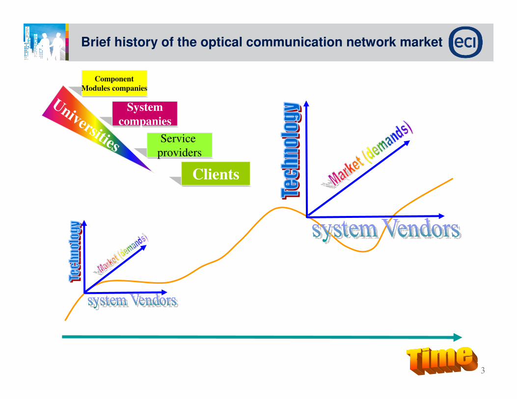
Brief history of the optical communication network market
Clients
Service
providers
System
companies
Component
Modules companies
Universities
4
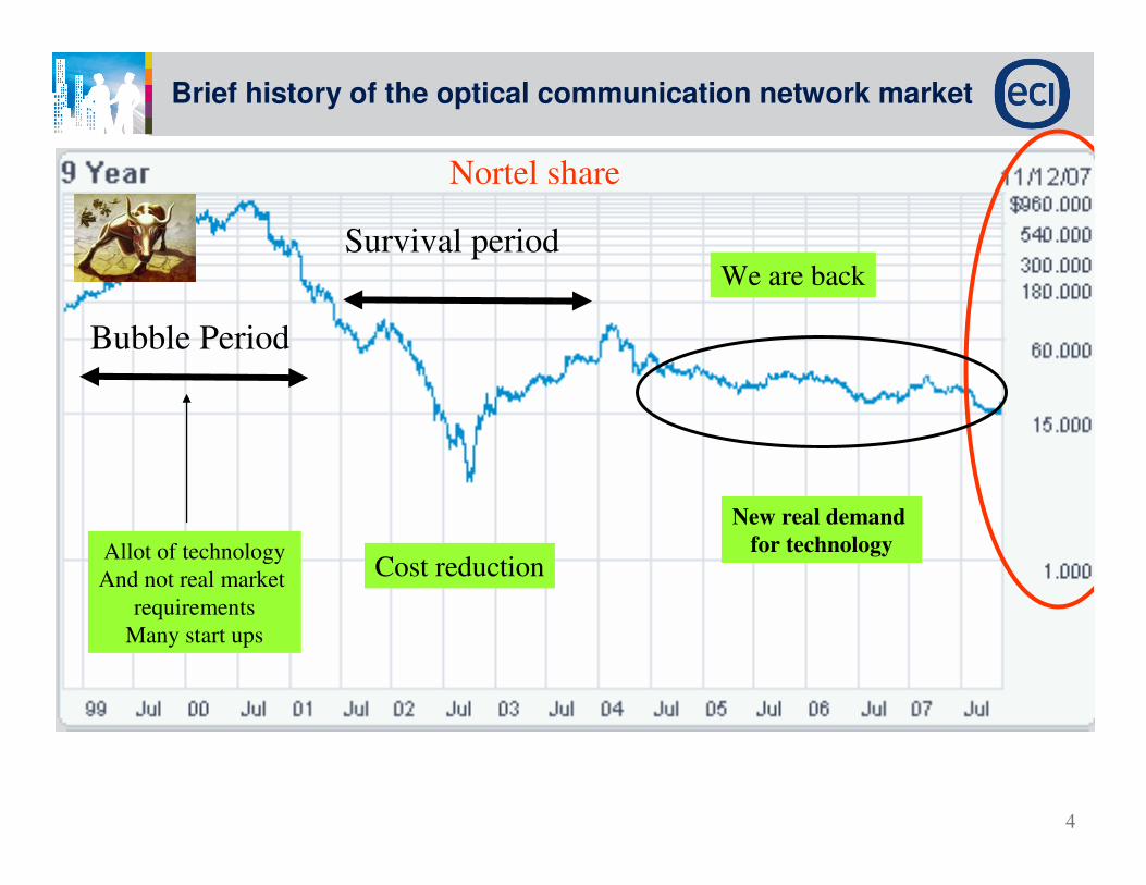
Brief history of the optical communication network market
Bubble Period
Allot of technology
And not real market
requirements
Many start ups
Survival period
Cost reduction
We are back
New real demand
for technology
Nortel share
5
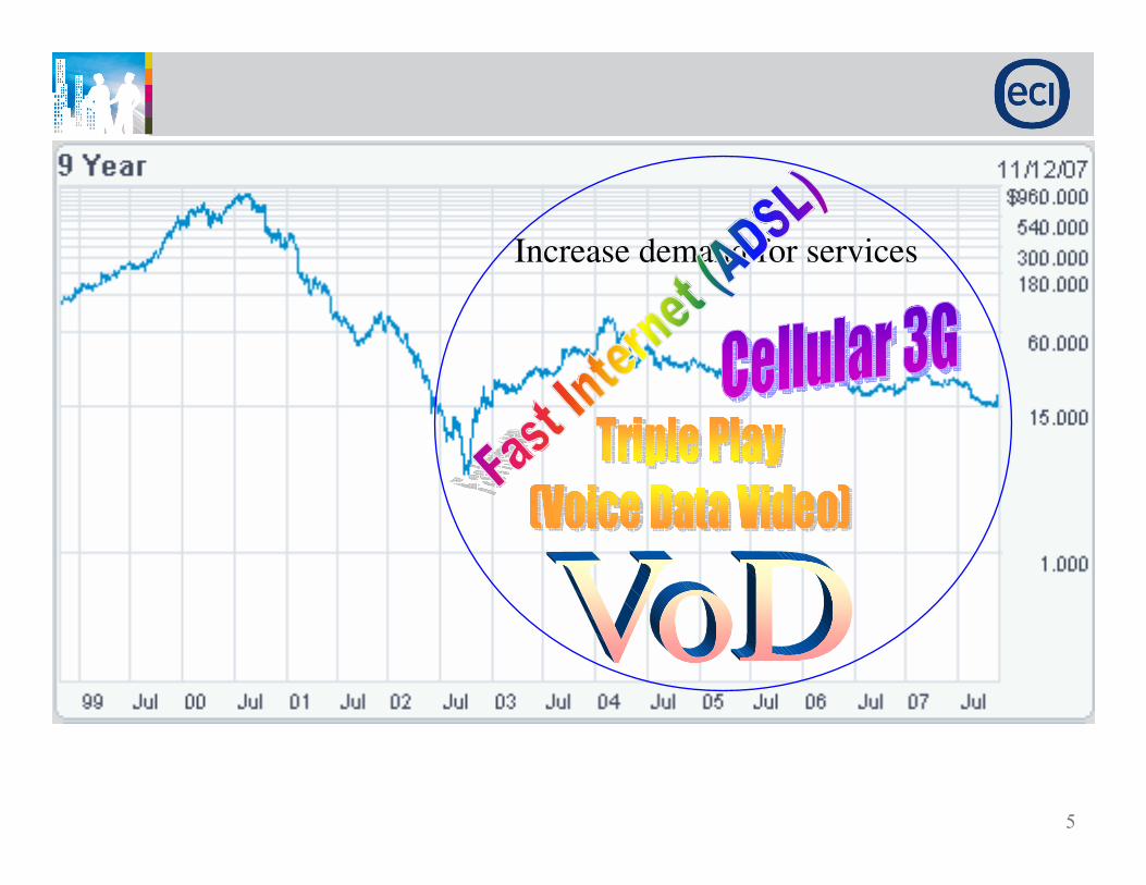
Increase demand for services

6
the market is driven also
by tough standards !!!

7
Market of Tough standards
Add some slides for showing - risks
8

9

10
Transition
To absorption of new technologies
form survival situation

11Confidential text here

12
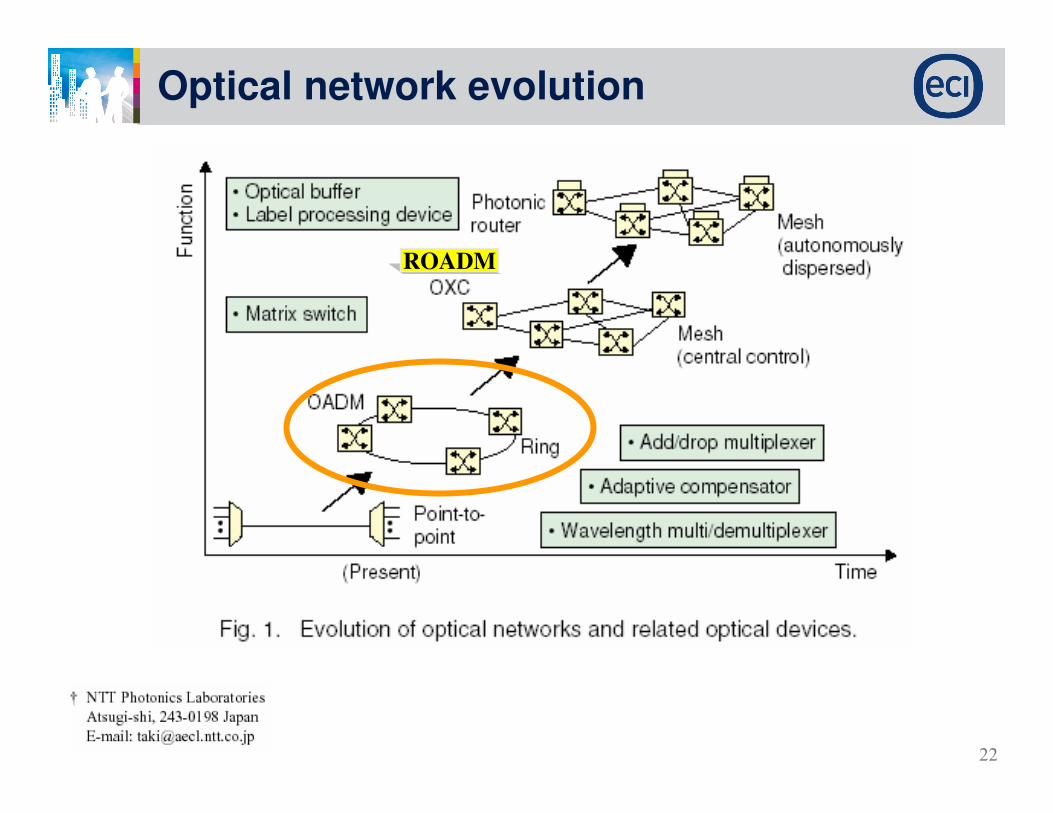
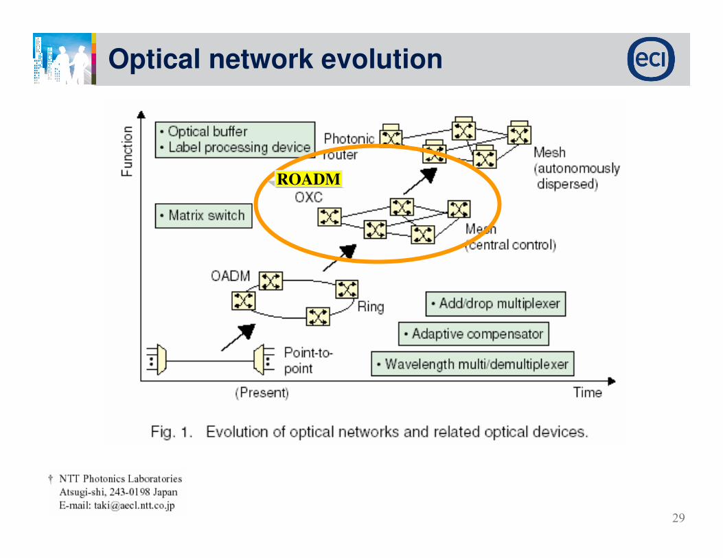
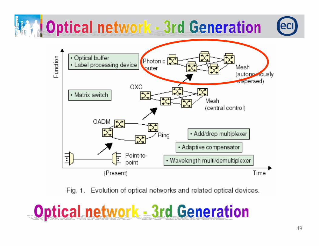
Optical network evolution
13
Design an optical network that answer the basic requirements from two point of views:
OLD requirementsConnectivity
Quality of Signal
Cost effective/ Competitive network
Problem Definition
14
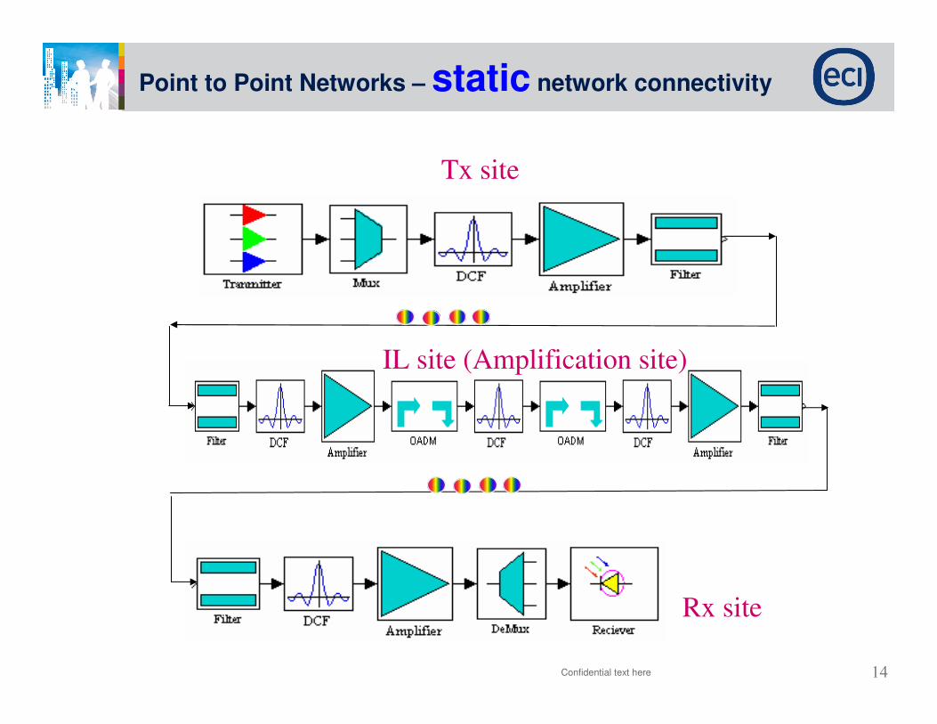
Point to Point Networks – static network connectivity
Confidential text here
Tx site
IL site (Amplification site)
Rx site
15
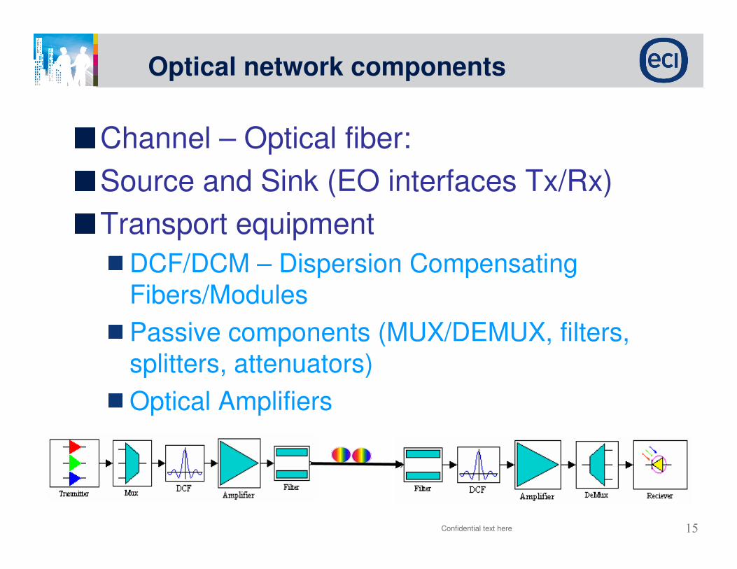
Optical network components
Confidential text here
Channel – Optical fiber:
Source and Sink (EO interfaces Tx/Rx)
Transport equipment
DCF/DCM – Dispersion Compensating Fibers/Modules
Passive components (MUX/DEMUX, filters, splitters, attenuators)
Optical Amplifiers

16
The optical fiber channel
Channel – Optical fiber:
Attenuation
Dispersion
Polarization mode dispersion
Non linearity
Attenuation
Rayleigh scattering is the main mechanism of attenuation
The most used band is 1529 ÷÷÷÷1560 nm called “C-band”
Typical attenuation of the C-band is 0.25 dB/km
Dispersion•Causes signal degradation as it passes
the fiber
•Depends on the wavelength
•It is a serious limitation on the signal
transmission distance
•Can be compensated
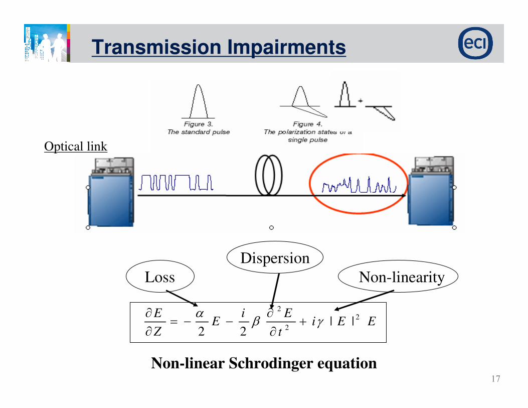
17
Optical link
Loss Non-linearity
EEit
EiE
Z
E 2
2
2
||22
γβα
+∂
∂−−=
∂
∂
Non-linear Schrodinger equation
Dispersion
Transmission Impairments
18
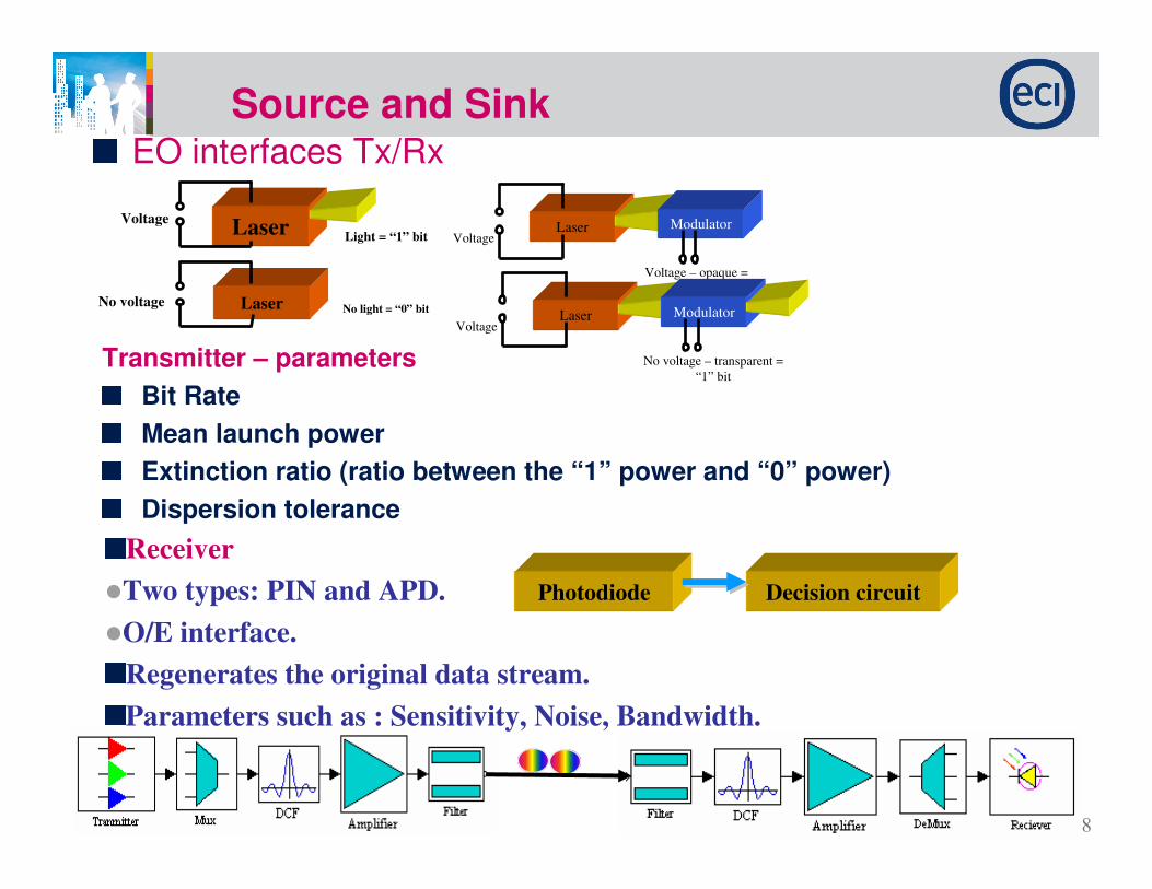
Source and Sink
Confidential text here
EO interfaces Tx/Rx
LaserVoltage
Light = “1” bit
LaserNo voltageNo light = “0” bit
LaserVoltage
Modulator
Voltage – opaque =
“0” bit
LaserVoltage
Modulator
No voltage – transparent =
“1” bitTransmitter – parameters
Bit Rate
Mean launch power
Extinction ratio (ratio between the “1” power and “0” power)
Dispersion tolerance
Receiver
�Two types: PIN and APD.
�O/E interface.
Regenerates the original data stream.
Parameters such as : Sensitivity, Noise, Bandwidth.
Photodiode Decision circuit

19
Multiplexer/Demultiplexers, Filters, DCF
Passive components (MUX/DEMUX, filters, splitters, attenuators, couplers)
Attenuation=Insertion loss
Bandwidth
Bandwidth shape
Technology
STAR coupler
AWG
λN
λ2
λ1
λ1
λ2
λN
.
.
.
.
.
.
FiberFiber
λ λ, . . .
λ1 2 N
, ,λ λ
, . . .λ
1 2 N, ,
Optical multiplexer Optical demultiplexer
•Needed for compensation of the chromatic dispersion
•Depends on the type of fiber
•Attenuation=Insertion loss
•Dispersion ripple
DCF/DCM - Dispersion compensation fiber/modules
20
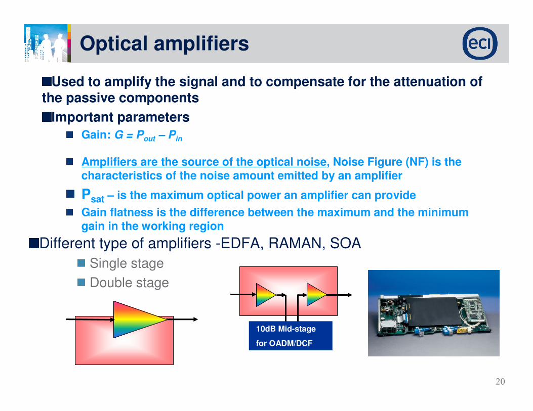
Optical amplifiers
Used to amplify the signal and to compensate for the attenuation of the passive components
Important parameters
Gain: G = Pout – Pin
Amplifiers are the source of the optical noise, Noise Figure (NF) is the characteristics of the noise amount emitted by an amplifier
Psat – is the maximum optical power an amplifier can provide
Gain flatness is the difference between the maximum and the minimum gain in the working region
Different type of amplifiers -EDFA, RAMAN, SOA
Single stage
Double stage
10dB Mid-stage
for OADM/DCF

21Confidential text here
22
Optical network evolution
ROADM
23
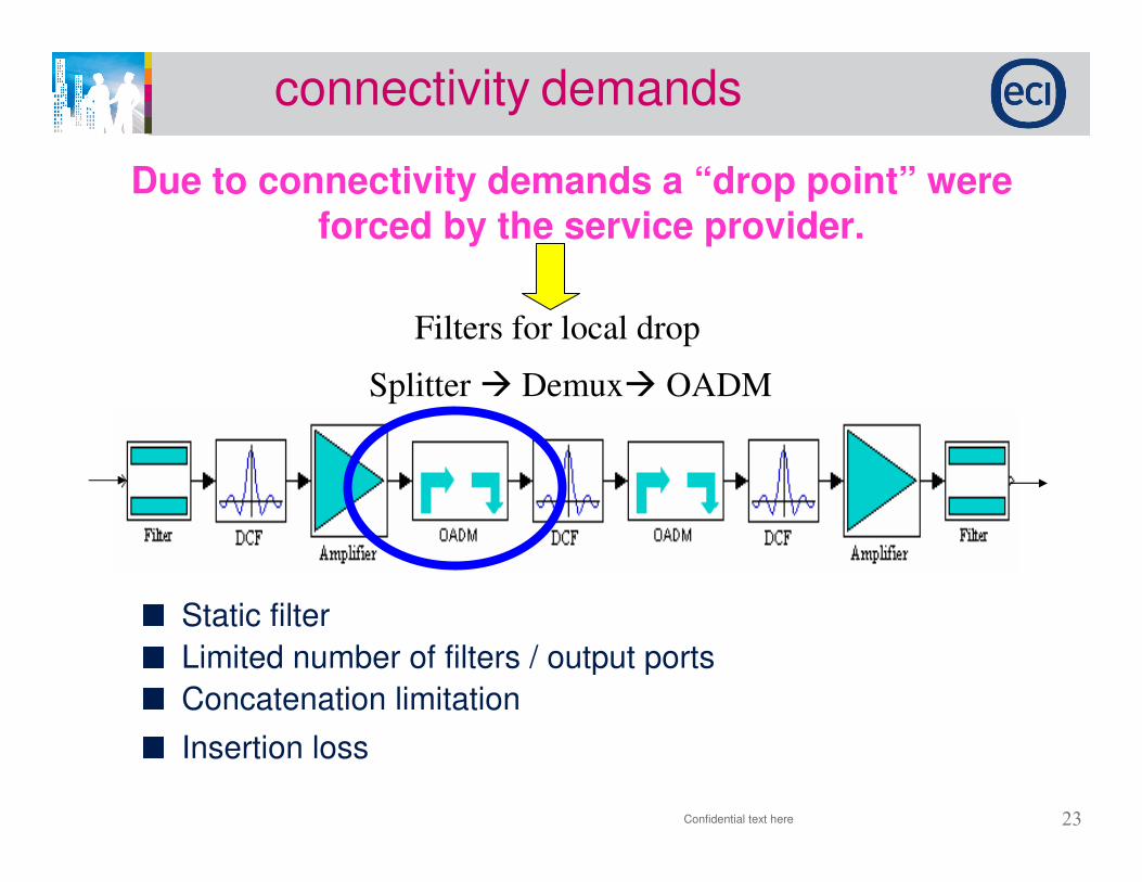
connectivity demands
Confidential text here
Due to connectivity demands a “drop point” were forced by the service provider.
Filters for local drop
Splitter � Demux� OADM
Static filter
Limited number of filters / output ports
Concatenation limitation
Insertion loss
24
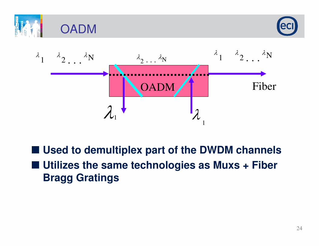
OADM
Used to demultiplex part of the DWDM channels
Utilizes the same technologies as Muxs + Fiber Bragg Gratings
OADM
λ λ. . .
λ1 2 N
Fiber
λ1 λ1
λ . . . λ2 Nλ λ
. . .λ
1 2 N

25
OADM – Optical Add Drop Multilpexing/filter
OADM – Bragg gratings
Periodical structure written on the fiber
Acts as a filter – reflects one wavelength and transmits other
Add Drop
Fiber Bragg grating
1 2
3λ1 λ2 λ3 λ4 λ1 λ2 λ3 λ4
λ2λ2
Coupler
OADM – parameters
•Through loss
•Add loss
•Drop loss
•Isolation – the amount of power,
which is transferred from one port to
another
26
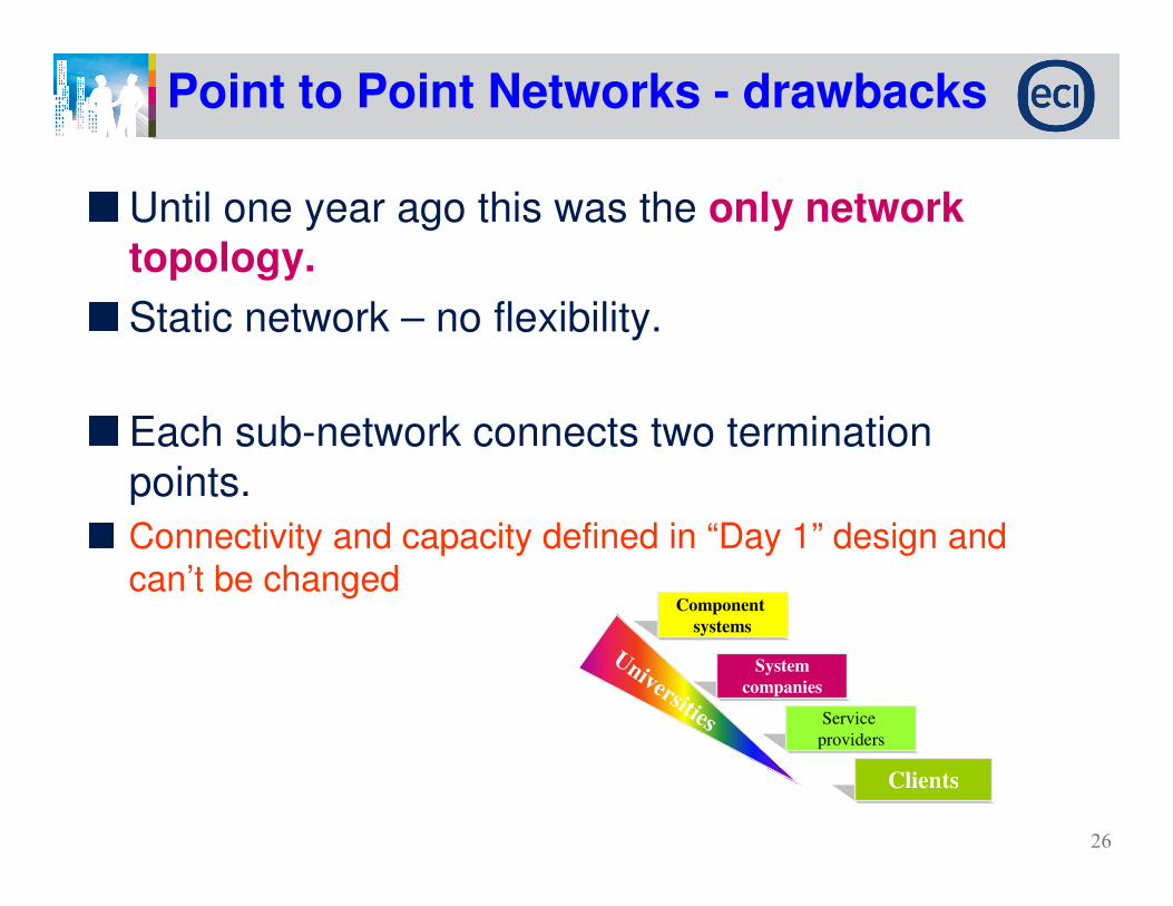
Until one year ago this was the only network
topology.
Static network – no flexibility.
Each sub-network connects two termination points.
Connectivity and capacity defined in “Day 1” design and can’t be changed
Point to Point Networks - drawbacks
Clients
Service
providers
System
companies
Component
systems
Universities
27
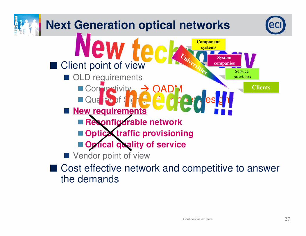
Next Generation optical networks
Confidential text here
Client point of viewOLD requirements
Connectivity
Quality of Signal
New requirements
Reconfigurable network
Optical traffic provisioning
Optical quality of service
Vendor point of view
Cost effective network and competitive to answer the demands
� OADM� Proper design
Clients
Service
providers
System
companies
Component
systems
Universities

28Confidential text here
29
Optical network evolution
ROADM
30Confidential text here
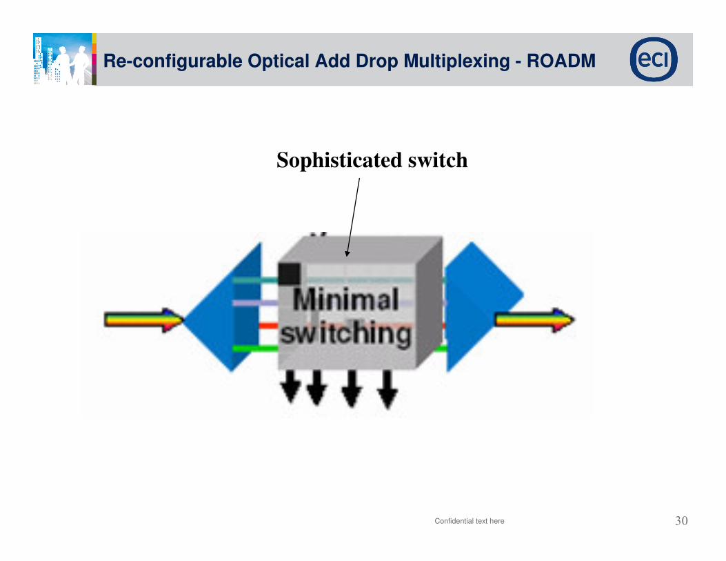
Re-configurable Optical Add Drop Multiplexing - ROADM
Sophisticated switch

31
WBWAVELENGTH
BLOCKER
Re-configurable Optical Add Drop Multiplexing - ROADM
WSSWAVELENGTH
SELECTIVE
SWITCH
PLCSilica-based
Planar
Lightwave
circuitOADM
ROADM
OXC
Technologies
&
Architecture
2nd generation
1.5st generation
2.Xnd generation
32
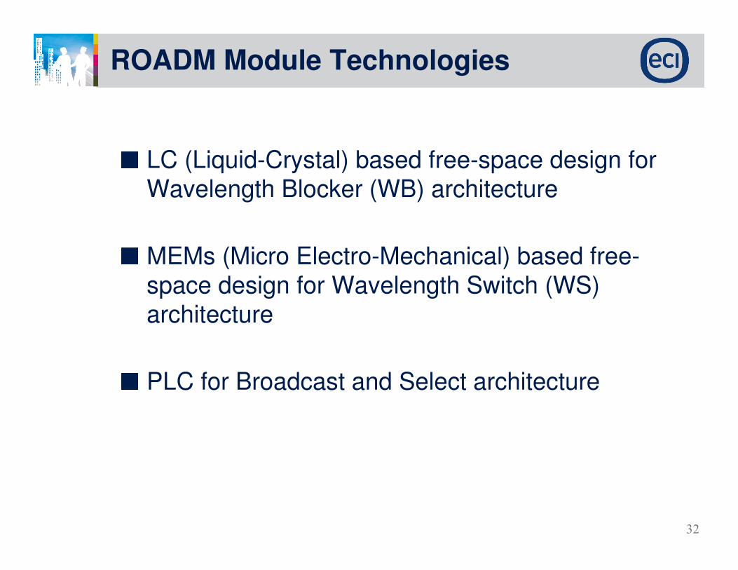
ROADM Module Technologies
LC (Liquid-Crystal) based free-space design for Wavelength Blocker (WB) architecture
MEMs (Micro Electro-Mechanical) based free-space design for Wavelength Switch (WS) architecture
PLC for Broadcast and Select architecture

33
LC Wavelength Blocker
Free space design is bulky and not scalable
Costly engineering design to ensure ruggedness against environmental variations
Cost of materials is high (~$6k), market value low (~$8k), no sign for cost reduction as key components have stabilized to fundamental limits (i.e. limited supplier base, low volumes and acceptable yields)
Diffraction grating
Folding mirror
Spherical Mirror
Liquid
crystal cell
(below)
Optical Bench
Front end
P1
P2
Grating
100x40x20 (mm)
Wavelength Blocker
34
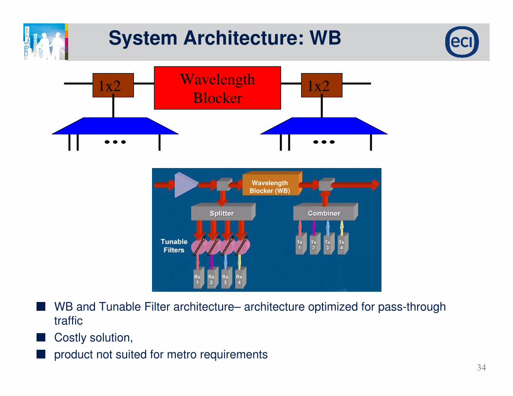
System Architecture: WB
WB and Tunable Filter architecture– architecture optimized for pass-through traffic
Costly solution,
product not suited for metro requirements
Wavelength
Blocker (WB)
$8k
1x2 1x2Wavelength
Blocker

35
MEMs Wavelength Switch
Bulky and costly design; 32 sequential MEMs array
Costly hermetic sealing to ensure moveable flaps (i.e. MEMs chip) does not “stick” because of contaminants
Also, cost of materials is high (~$18k), cost reduction curve still not clear
Current market value is $24k for a 8-channel add/drop
IN
OUTExpress
INAdd
OUTDrop
Fibers
Micro
LensesSelfocLens
Sphericalmirror
DiffractionGrating
32 MEMS
Micro-Mirror Array

36
Micro-Electro-Mechanical Systems (MEMS)
Micro-Electro-Mechanical Systems (MEMS) is the integration of mechanical elements, sensors, actuators, and electronics on a common silicon substrate through microfabrication technology.
Electronics are fabricated using integrated circuit (IC) process sequences (e.g., CMOS, Bipolar, or BICMOS processes).
The micromechanical components are fabricated using compatible "micromachining" processes that selectively etch away parts of the silicon wafer or add new structural layers to form the mechanical and electromechanical devices.
37
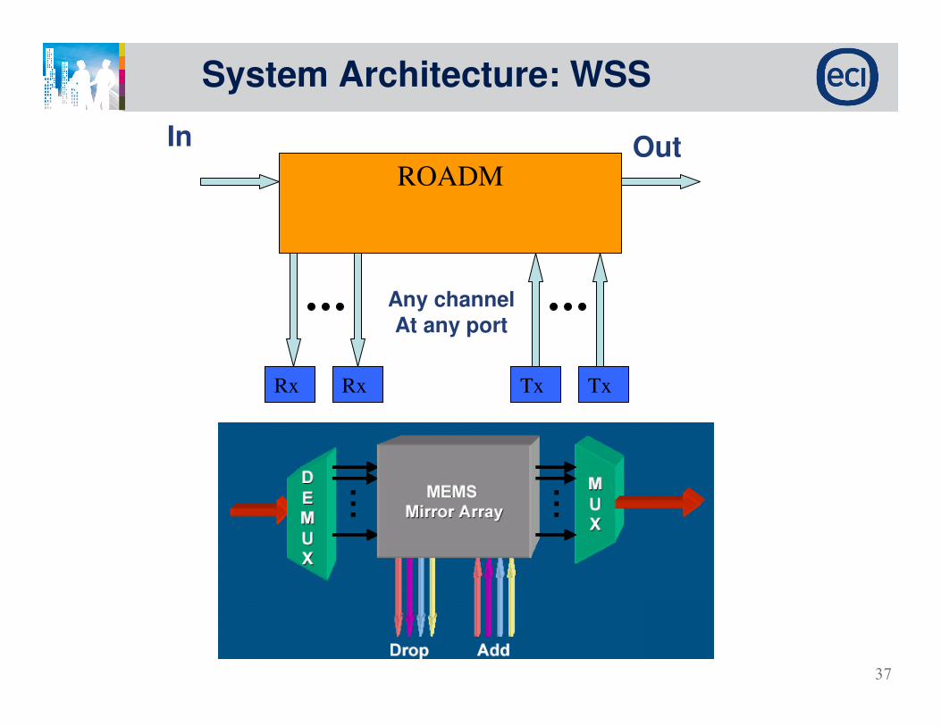
System Architecture: WSS
ROADM
Rx Rx Tx Tx
In Out
Any channel
At any port

38Confidential text here
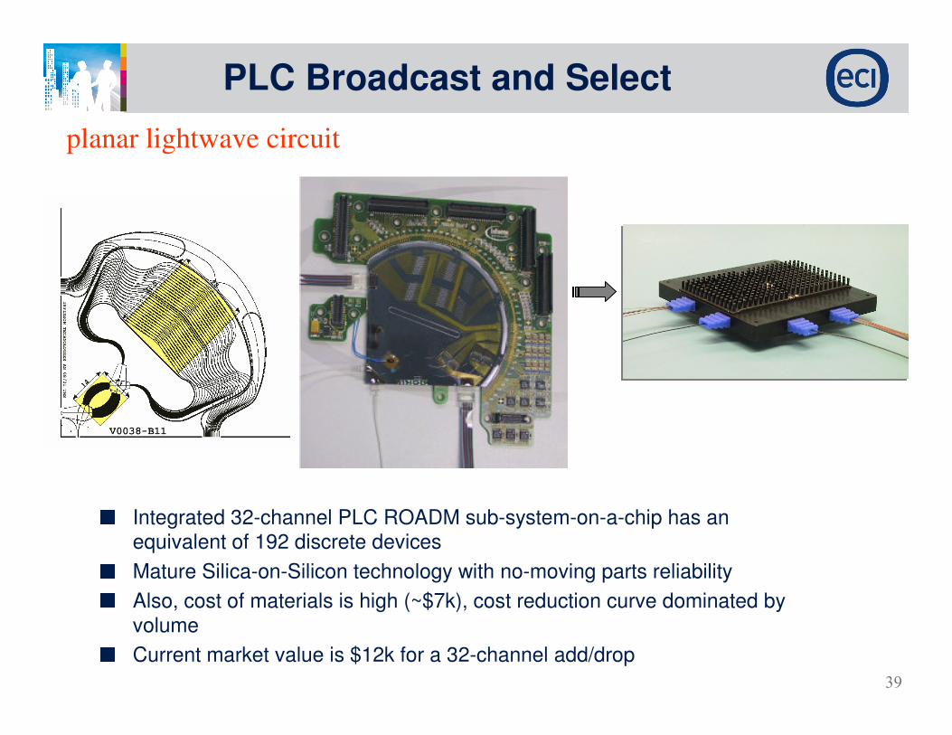
PLC - planar lightwave circuit
•optical devices that can process optical signals
directly in the optical layer
•essential for the construction of next-generation
advanced optical networks.
•Making full use of the superior characteristics of
waveguides formed by planar lightwave circuit
(PLC) technology.
• can perform highspeed and flexible optical-signal
processing for various purposes.
39
PLC Broadcast and Select
Integrated 32-channel PLC ROADM sub-system-on-a-chip has an equivalent of 192 discrete devices
Mature Silica-on-Silicon technology with no-moving parts reliability
Also, cost of materials is high (~$7k), cost reduction curve dominated by volume
Current market value is $12k for a 32-channel add/drop
planar lightwave circuit

40
ROADM Summary
Confidential text here
Local ADD/ DROP features as OADM
Advantages:Reconfigurable
Number of active drops
Connectivity – channel assignment in each port.
First generation of the OXC
Disadvantage:High insertion loss
Non mature technology although proved.
Weak standardization
Still expensive
Based mechanical - ??? Vibration/end of life edge effects
Based PLC – No”Multi degree” feature

41Confidential text here
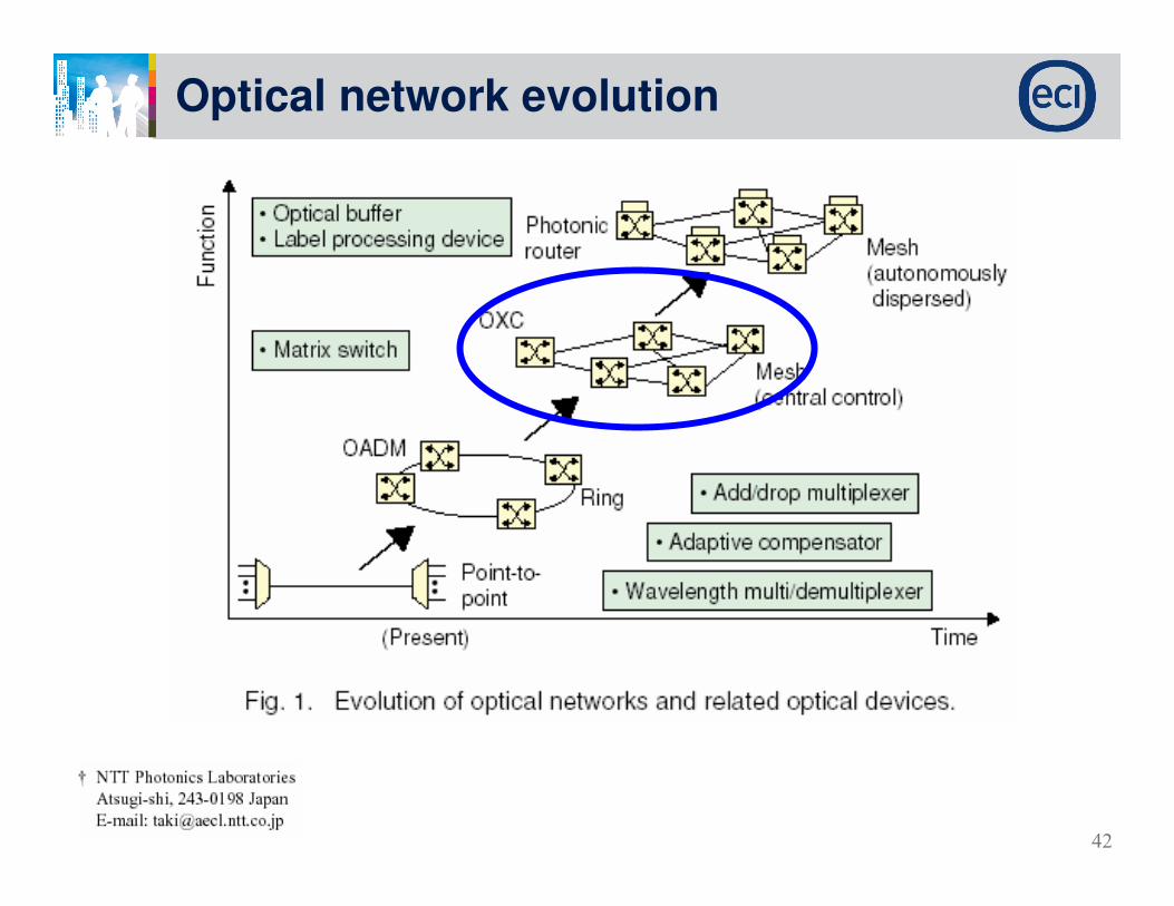
42
Optical network evolution

43Confidential text here
End to end automation � Insert Lambda turn-up assuming pre-deployment
Any-Port Reconfigurable OADM � OXC

44
Next Generation architecture
fiber

45
Mesh network
What do we expect from the Mesh network
New requirements Dynamic and fast connectivity
Quality of Signal � Quality of Service
Optical traffic provisioning
Cost effective/ Competitive network
Mesh + reconfigurability achieved by ROADM
Physical limitation Fiber/distance
Control plan routing
Reconfigurable elements
OSNR
No Linearity

46
Physical layer design – MESH challenges
Tx OE OE OE OE
You change here
You influence here
OE OE OE
OE OE OE OE
OE OE OE
OE OE OE OE Rx
How do we find a path? WRA
How do we find a protection path? WRAHow we understand that the path we’ve found is good?
Or here
How do we plan?
Or here
Or any other Rx
47Confidential text here
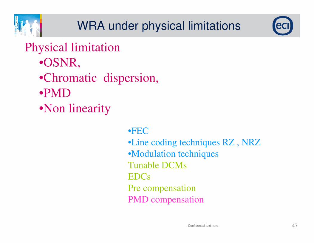
Physical limitation
•OSNR,
•Chromatic dispersion,
•PMD
•Non linearity
WRA under physical limitations
•FEC
•Line coding techniques RZ , NRZ
•Modulation techniques
Tunable DCMs
EDCs
Pre compensation
PMD compensation

48
Mesh Problem Definition
GivenA set of nodes
Fibers Physical details and infrastructure
Given traffic table connectivity
Constraint Wavelength allocation – Difficult optimization problem
Bit rates
BER/OSNR
cost
ObjectiveFind the Optimum (i.e., minimum cost) network(s)
Optical QoSAdaptive bit Rate / Capacity / Decrease BER to moderate level.
Confidential text here
49

50
conclusions
1) Today market encourages the technology
2) Optical networks transition from static to intelligent
Re-configurable service oriented networks
3) ROADM/OXC are the main Key Technologies
4) Physical limitation are still the main challenge !!!

51Confidential text here
Thank
you