Dr Stephen Marich - Marich Consulting Services - Module 4: Wheel and rail profiles
26
Wheel/Rail Interface Forum – Brisbane, May 2014 Wheel and Rail Profiles The Wheel/Rail Interface
-
Upload
informa-australia -
Category
Business
-
view
551 -
download
9
description
Dr Stephen Marich delivered the presentation at 2014 RISSB Wheel Rail Interface Forum. The RISSB Wheel Rail Interface Forum reviewed the fundamentals of what happens between wheel and rail before focusing on the practicalities of monitoring, interventions, maintenance, management and the critical importance of the interdisciplinary cooperation. For more information about the event, please visit: http://www.informa.com.au/wheelrailinterface14
Transcript of Dr Stephen Marich - Marich Consulting Services - Module 4: Wheel and rail profiles

Wheel/Rail Interface Forum – Brisbane, May 2014
Wheel and Rail Profiles
The Wheel/Rail Interface

Wheel/Rail Interface Forum – Brisbane, May 2014
The Basics
For new wheels in equilibrium position (wheelset centre = track centre), R is generally 0
Rolling Radius Differential (R)
R = RLR – RRR = 0
Rail C/L Rail C/L
Left Rail Right
Rail
RLR RRR
Track C/L
Wheelset C/L

Wheel/Rail Interface Forum – Brisbane, May 2014
The Basics
C/L of Track
Right Rail (Low)Left Rail (High)
RhrRlr
C/L of Wheelset
y
Rolling Radius DifferentialHowever, as wheelset moves towards one rail (Left), RLR > RRR
When RLR > RRR wheelset tries to move back to equilibrium
position (R = 0) Wheelset Steering (Creep Forces)

Wheel/Rail Interface Forum – Brisbane, May 2014
The Basics
Conicity
Conicity () of wheel = angle between wheel tread and horizontal axis of axle
For cylindrical
wheel = 0
For conical tread
wheel with 1:20
taper = 0.05
Horizontal Line of
Axle
Vertical1:20 Conical Wheel
Tread
Rail Centre
Line
Conicity (1:20)

Wheel/Rail Interface Forum – Brisbane, May 2014
The Basics
As wheels and rail become worn or special tread profiles areused, the conicity will depend on the lateral location of thewheelset relative to the rail. In this case, the term “effectiveconicity” (eff) is used.
Effective Conicity
C/L of Track
Right Rail (Low)Left Rail (High)
RhrRlr
eff
C/L of Wheelset
y
eff = 0.5 R/y
R = Rhr - Rlr

Wheel/Rail Interface Forum – Brisbane, May 2014
Rolling Radius Differential Vs Effective Conicity
An increase in R leads to improved wheelset steering in curved track and hence reduced wear but higher creep forces and hence more surface defects.
An increase in R also leads to an increase in eff.
High eff leads to wheelset/bogie instability in shallow curves and tangent track (hunting), which reduces the safe operating speed.
Hence, sharp curves need higher R/higher eff and shallow curves/tangent track need lower R/lower eff..
Conflicting requirements achieved by modifying the rail profiles by grinding
R = Rhr – Rlr eff = 0.5 R/y
The Requirements

Wheel/Rail Interface Forum – Brisbane, May 2014
The Requirements
As R increases, steering increases.
Hence, sharper curves need wheel/rail profiles that give higher R.
Right/Low Rail
Conical
Wheel
Profiled or worn
Rail/Wheel
Profiled Rail
and Wheel
Track Centre
Wheelset Lateral
Position (y)
Rolling Radius
Difference (r)
Flanging
Left/High Rail
Curved Track
Requirements
Tangent Track
Requirements
Curved Track
Requirements
Tangent Track
Requirements
Wheel/Rail Interface Forum – Brisbane, May 2014
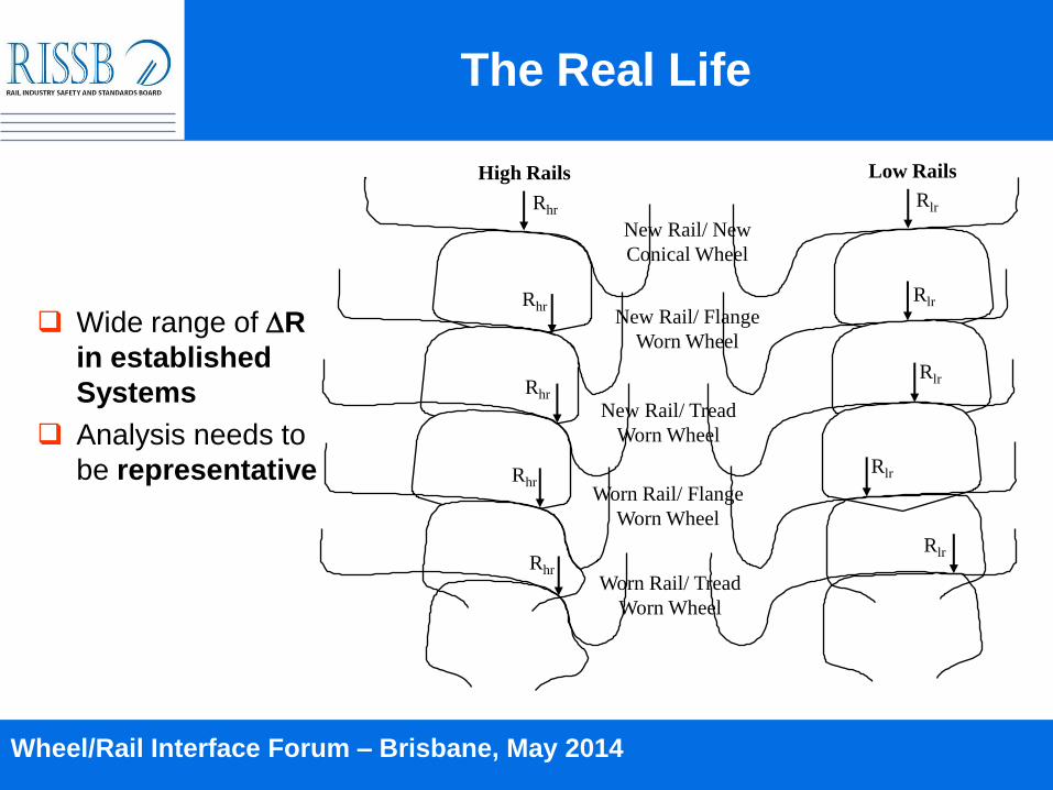
The Real Life
New Rail/ New
Conical Wheel
High Rails Low Rails
New Rail/ Flange
Worn Wheel
New Rail/ Tread
Worn Wheel
Worn Rail/ Flange
Worn Wheel
Worn Rail/ Tread
Worn Wheel
RhrRlr
RhrRlr
Rhr
Rlr
RhrRlr
Rhr
Rlr
Wide range of R
in established
Systems
Analysis needs to
be representative

Wheel/Rail Interface Forum – Brisbane, May 2014
Wheel/Rail Profiling
Aim to control R, eff and contact characteristics,
and hence wheelset steering characteristics,
dynamics and contact stresses.

Wheel/Rail Interface Forum – Brisbane, May 2014
The General Requirements
The wheel and rail profiles
should have conformal contact
to reduce the contact stresses.
Aim to avoid field side contact,
which leads to high contact
stresses and plastic flow.
Also produces rail head rotation
and hence reduced allowable
rail head wear limits.

Wheel/Rail Interface Forum – Brisbane, May 2014
The General Requirements
Field Side Contact – Function of Both Rail and Wheel
Profiles and Maintenance
Rail Rotation
Tread Hollowing
Low Rail Contact
Eccentric Load
Central Contact is
Best
Higher Critical
Stresses

Wheel/Rail Interface Forum – Brisbane, May 2014
The General Requirements
High leg of relatively sharp curves:
Relatively conformal contact between
rail gauge corner and wheel throat
extending almost to the centre of the
rail to:
Reduce contact stresses (hence
RCF)
Reduce two point contact (hence
wear)
Increase rolling radius differential
(hence improve wheelset steering)
A minor undercut in gauge corner
region may also be applied to
reduce contacts (care is required
since excessive undercut will lead
to high wear rate)
Large
Conformal
Contact
Low Stresses
Wheel/Rail Interface Forum – Brisbane, May 2014
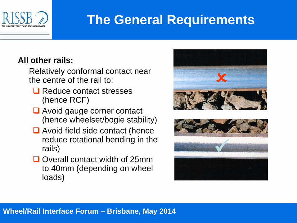
All other rails:
Relatively conformal contact near the centre of the rail to:
Reduce contact stresses (hence RCF)
Avoid gauge corner contact (hence wheelset/bogie stability)
Avoid field side contact (hence reduce rotational bending in the rails)
Overall contact width of 25mm to 40mm (depending on wheel loads)
The General Requirements
Wheel/Rail Interface Forum – Brisbane, May 2014
The General Steps
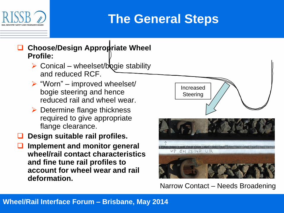
Choose/Design Appropriate Wheel Profile:
Conical – wheelset/bogie stability and reduced RCF.
“Worn” – improved wheelset/ bogie steering and hence reduced rail and wheel wear.
Determine flange thickness required to give appropriate flange clearance.
Design suitable rail profiles.
Implement and monitor general wheel/rail contact characteristics and fine tune rail profiles to account for wheel wear and rail deformation.
Increased
Steering
Narrow Contact – Needs Broadening
Wheel/Rail Interface Forum – Brisbane, May 2014
The Flange Thickness
70 60 50 40 30 20
10 0
-40 -30 -20 -10 0 10 20 30 40
a x x
b c c 16mm
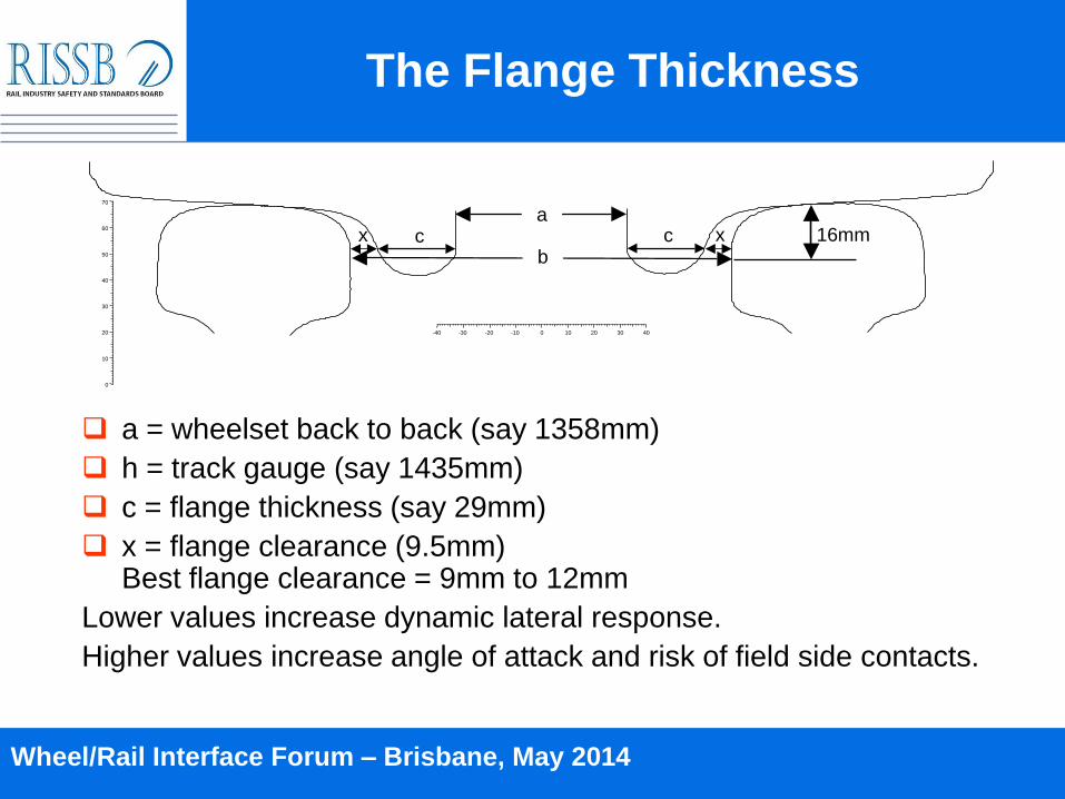
a = wheelset back to back (say 1358mm)
h = track gauge (say 1435mm)
c = flange thickness (say 29mm)
x = flange clearance (9.5mm)Best flange clearance = 9mm to 12mm
Lower values increase dynamic lateral response.
Higher values increase angle of attack and risk of field side contacts.

Wheel/Rail Interface Forum – Brisbane, May 2014
The Implementation
Now accepted practice in majority of Systems
Rail Grinding

Wheel/Rail Interface Forum – Brisbane, May 2014
The Monitoring – Manual

Wheel/Rail Interface Forum – Brisbane, May 2014
The Monitoring – Automatic
Laser based Systems.
Currently mostly used for general wear analysis, for example:
Rail gauge face and wheel flange wear.
Rail running surface wear.
Wheel tread hollowing.

Wheel/Rail Interface Forum – Brisbane, May 2014
If You Get It Right
Improve wheel/rail interaction characteristics.
Control of corrugations, dipped welds and joints.
Control of RCF and other defects.
Increase allowable rail wear limits.
Improve wheelset/bogie dynamics (hunting).
Reduce adverse influence of „rogue‟ wheels/bogies.
Control track gauge.
Reduce noise/vibrations.
Moderate adverse influence of higher axle loads.

Wheel/Rail Interface Forum – Brisbane, May 2014
The Benefits – Wear
For poor profiles note:
Increased wear rate (x 2-4)
Increased curve radius of flanging wheels
General Effect of Profiles on Flange Energy (Wear),
Lubricated
0
20
40
60
80
100
120
140
160
180
200
200 300 400 500 600 700 800 900 1000
Curve Radius (m)
Fla
ng
e E
nerg
y (
Wear)
(N
m/m
)
Narrow Conformal Gauge Corner Contact
Broad Conformal Gauge Corner Contact
Mild Gauge Corner Undercut
Heavy Gauge Corner Undercut
Wheel/Rail Interface Forum – Brisbane, May 2014
The Benefits – Allowable Wear Limit
C/L
22.5mm15mm
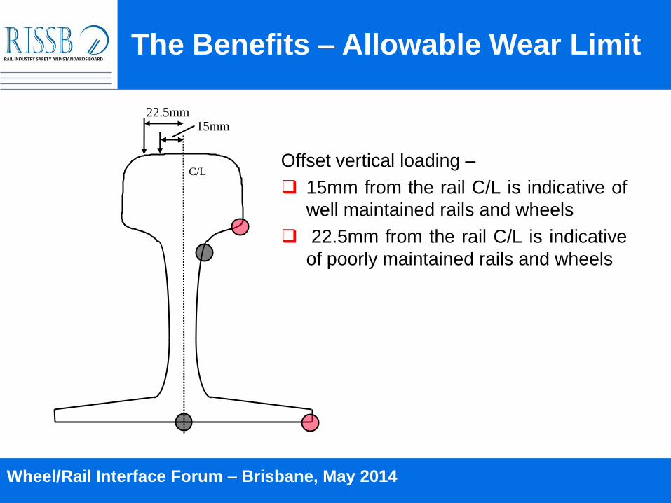
Offset vertical loading –
15mm from the rail C/L is indicative of
well maintained rails and wheels
22.5mm from the rail C/L is indicative
of poorly maintained rails and wheels

Wheel/Rail Interface Forum – Brisbane, May 2014
The Benefits – Allowable Wear Limit
Note: Control of wheel/rail contact
increases allowable rail head wear limit in SC rails from 27% to
45%
Effect of Wheel Load Eccentricity on Rail Stresses and
Wear Limits
0
100
200
300
400
500
600
700
800
900
0 5 10 15 20 25 30 35 40 45 50 55 60 65 70
Percentage Rail Head Loss
Str
ess (
MP
a)
L/V=0.2, @ 15mm load eccentricity
L/V=0.2, @ 22.5mm load eccentricity
347 MPa, Stress Limit
for SC Rails

Wheel/Rail Interface Forum – Brisbane, May 2014
0.0
0.5
1.0
1.5
2.0
2.5
40 45 50 55 60 65 70 75 80 85 90
Speed (kph)
Conformal Contact
Two Point Contact
Conformal Contact + Friction Mod
Hu
nti
ng
Severi
ty I
nd
ex
Severe
Hunting
The Benefits – Reduced Hunting

Wheel/Rail Interface Forum – Brisbane, May 2014
Getting it Wrong
Insufficient metal removal from contact surface (required to control surface defects).
Out of tolerance profiles.
Excessive undercutting in the rail gauge corner region.
Excessive time between maintenance cycles in both wheels and rails.
Insufficient time for completion of maintenance (poor planning).
Introduction (rather than removal) of surface irregularities.
Note: Profiles can last a long time and hence the consequences

Wheel/Rail Interface Forum – Brisbane, May 2014
Surface Condition After Grinding

Wheel/Rail Interface Forum – Brisbane, May 2014
Concluding Remarks –
Wheel/Rail Profiles
Wheel and rail profiles have a very substantial influence on a wide range of factors, including:
Wheel and rail lives.
Defect development
Noise and vibration.
Wheelset and bogie dynamics (and hence operating speeds).
The main stages of establishing the best profiles strategy are:
Identify main requirements:
Wear and Lubrication Vs Defects and Stability
Design of the profiles (consider actual track/vehicle condition)
Implementation, monitoring of performance and fine tuning.
Planning of the required rail maintenance activities.
Commitment to a long term maintenance strategy.