Dr Robert Loss Room 301-143 Telephone 351 7747 : Fax 351 2377 Email [email protected] Dr...
34
Dr Robert Loss Room 301-143 Telephone 351 7747 : Fax 351 2377 Email [email protected] Physics 114 Physics 114 Lecture 6 Lecture 6 Electromagnetic Electromagnetic induction induction Perth Western Australia University of Technology School of Physical Sciences Department of Applied Physics
-
Upload
dominick-richard -
Category
Documents
-
view
219 -
download
0
Transcript of Dr Robert Loss Room 301-143 Telephone 351 7747 : Fax 351 2377 Email [email protected] Dr...
Dr Robert LossRoom 301-143
Telephone 351 7747 : Fax 351 2377Email [email protected]
Dr Robert LossRoom 301-143
Telephone 351 7747 : Fax 351 2377Email [email protected]
Physics 114Physics 114Lecture 6Lecture 6
Electromagnetic Electromagnetic inductioninduction
Perth Western AustraliaUniversity of Technology
School of Physical Sciences
Department of Applied Physics

2Curtin University P114 1995
Electromagnetic Electromagnetic inductioninduction
• A changing magnetic field can produce (induce) an electrical potential in a conductor
• Moving a conductor through a magnetic field can produce (induce) an electrical potential in the conductor
• The direction of the induced current opposes the change in the magnetic field
• The advantages of alternating current over direct current
THE BIG IDEAS
3Curtin University P114 1995
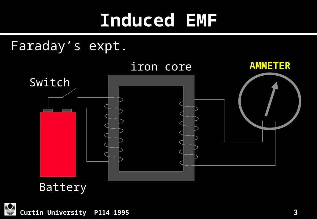
Induced EMFFaraday’s expt.
iron coreSwitch
Battery
AMMETER
4Curtin University P114 1995
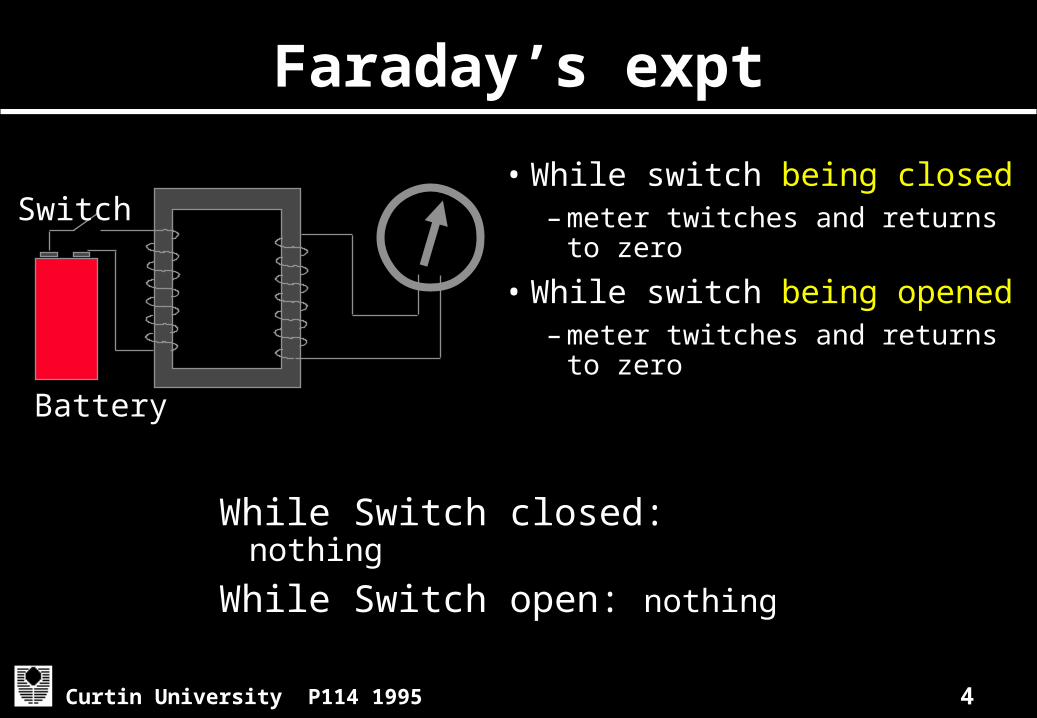
Faraday’s expt
• While switch being closed– meter twitches and returns
to zero
• While switch being opened– meter twitches and returns
to zero
While Switch closed: nothing
While Switch open: nothing
Switch
Battery
5Curtin University P114 1995
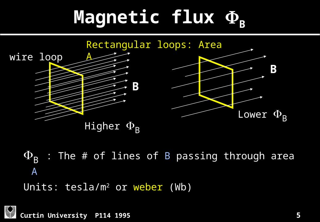
B : The # of lines of B passing through area A
Units: tesla/m2 or weber (Wb)
Magnetic flux B
Higher B
Lower B
Rectangular loops: Area Awire loop
B
B
6Curtin University P114 1995
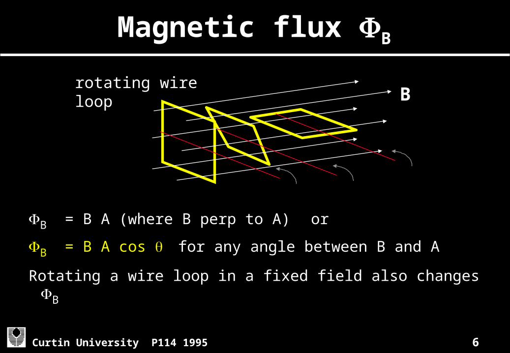
Magnetic flux B
B = B A (where B perp to A) or
B = B A cos for any angle between B and A
Rotating a wire loop in a fixed field also changes B
rotating wire loop B
7Curtin University P114 1995
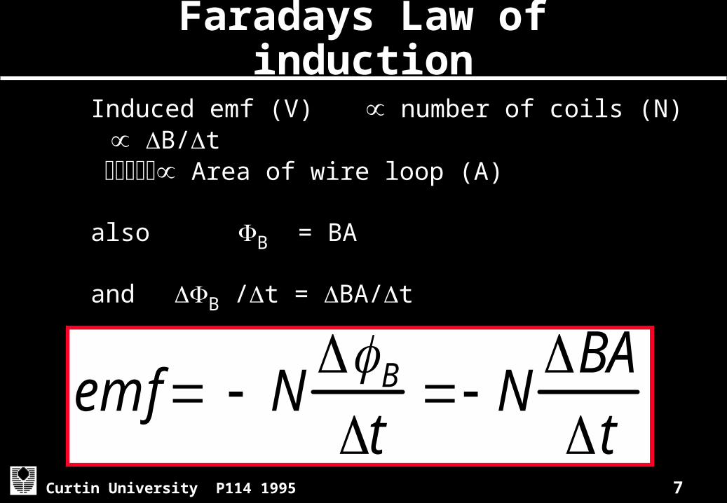
Faradays Law of induction
Induced emf (V) number of coils (N) B/t Area of wire loop (A) also B = BA
and B /t = BA/t
emf NBt
NBAt
8Curtin University P114 1995
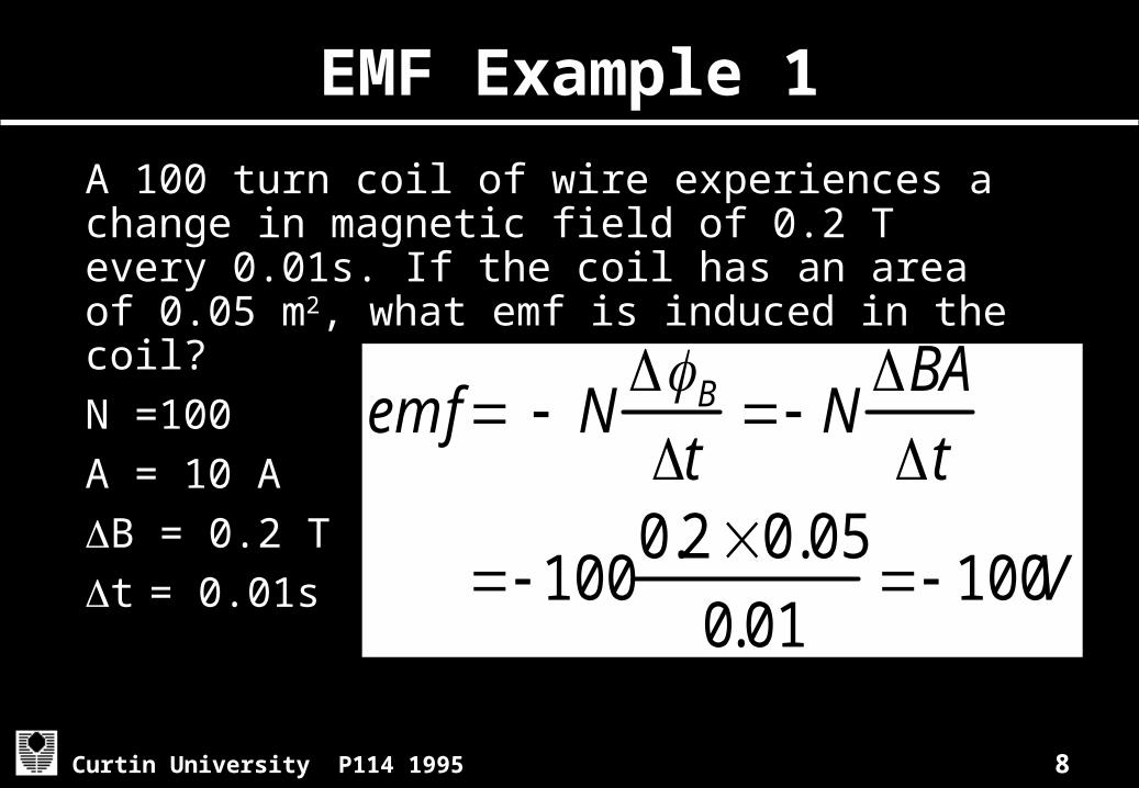
EMF Example 1
A 100 turn coil of wire experiences a change in magnetic field of 0.2 T every 0.01s. If the coil has an area of 0.05 m2, what emf is induced in the coil?N =100A = 10 AB = 0.2 Tt = 0.01s
emf NBt
NBAt
1000.2 0.05
0.01 100V

9Curtin University P114 1995
Why the negative sign?
What is the direction of the induced current?Consider a static conductor in a region where B is as shown below AND increasing.
Binducing increasing
X
oooo
XXX
(i) ?
10Curtin University P114 1995
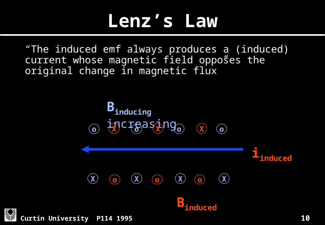
Lenz’s Law
“The induced emf always produces a (induced) current whose magnetic field opposes the original change in magnetic flux”
Binducing increasing
X
o
o
o
o
o
o
o X
X
X
X
X
X
Binduced
iinduced

11Curtin University P114 1995
Consequences of Lenz’s Law
If Lenz’s Law was not correct the induced Binduced would ADD to the Binducing
- producing more iinduced
- producing more Binduced
- etc . . . . . . - leading to a “runaway” production of
current and finally wire meltdown.
12Curtin University P114 1995
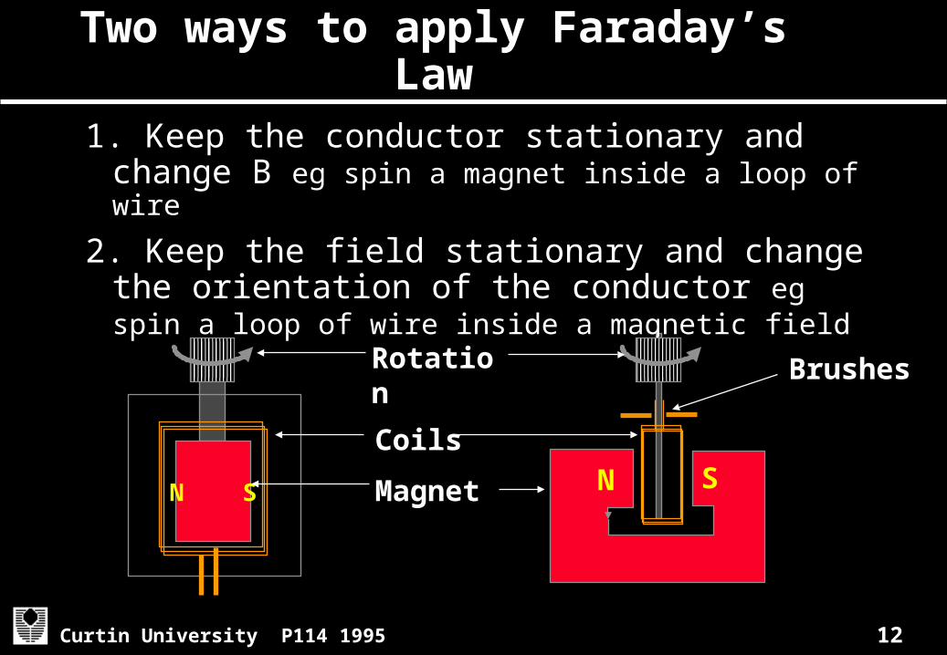
Two ways to apply Faraday’s Law
1. Keep the conductor stationary and change B eg spin a magnet inside a loop of wire
2. Keep the field stationary and change the orientation of the conductor eg spin a loop of wire inside a magnetic field
N S N SMagnet
Coils
Rotation
Brushes

13Curtin University P114 1995
Applying Faraday’s Law
move a conductor through a magnetic field eg moving a length of wire inside a magnetic field
conductive loop
Bvelocity v
o
o
o
o
o
o
o
o
o
o
o
o
o
o
o
o
o
o
o
o
o
o
o
o
l
area A, covered per unit time t
14Curtin University P114 1995
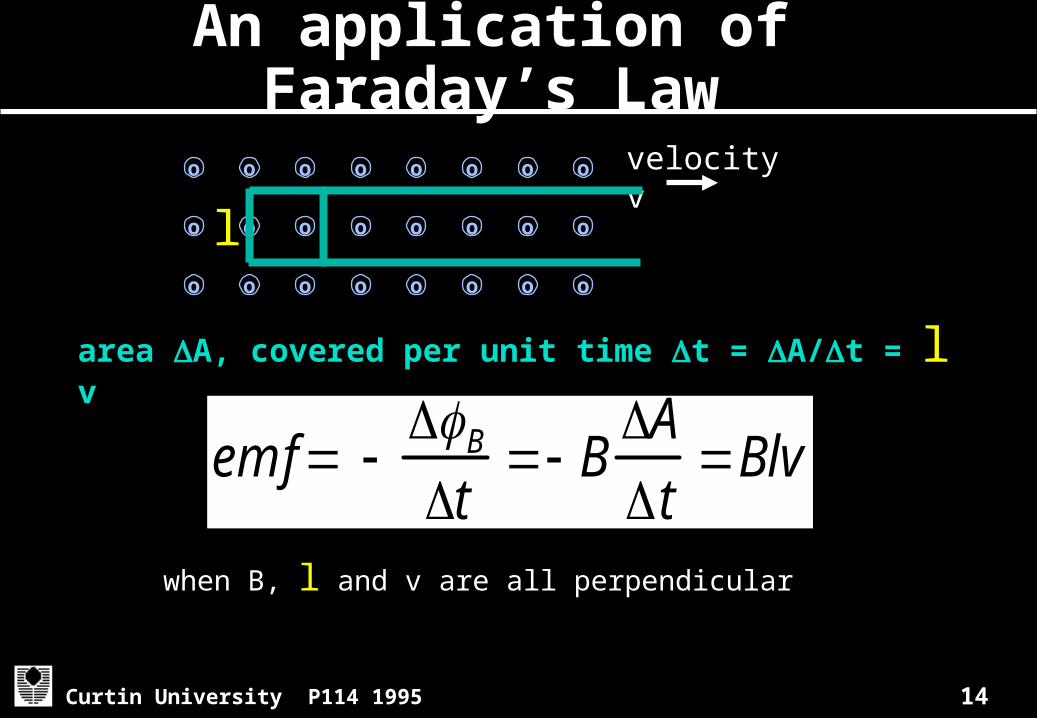
An application of Faraday’s Law
when B, l and v are all perpendicular
area A, covered per unit time t = A/t = l v
velocity vo
o
o
o
o
o
o
o
o
o
o
o
o
o
o
o
o
o
o
o
o
o
o
o
l
emf Bt
BAt
Blv
15Curtin University P114 1995
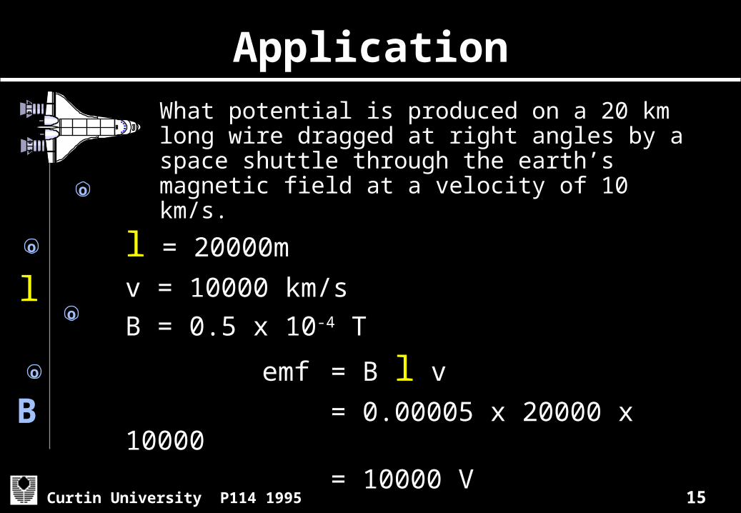
ApplicationWhat potential is produced on a 20 km long wire dragged at right angles by a space shuttle through the earth’s magnetic field at a velocity of 10 km/s.
l = 20000m
v = 10000 km/sB = 0.5 x 10⁻⁴ T
emf = B l v = 0.00005 x 20000 x 10000 = 10000 V
l
o
o
o
o
B

16Curtin University P114 1995
AC signals
V
time
Vo
Any signal (eg voltage) component which changes periodically over time
Vo = Vp =maximum voltage
VPP = peak to peak voltage = 2 x Vp
Period (T) time for one cycle Frequency (f) = 1/T
VPPT
17Curtin University P114 1995
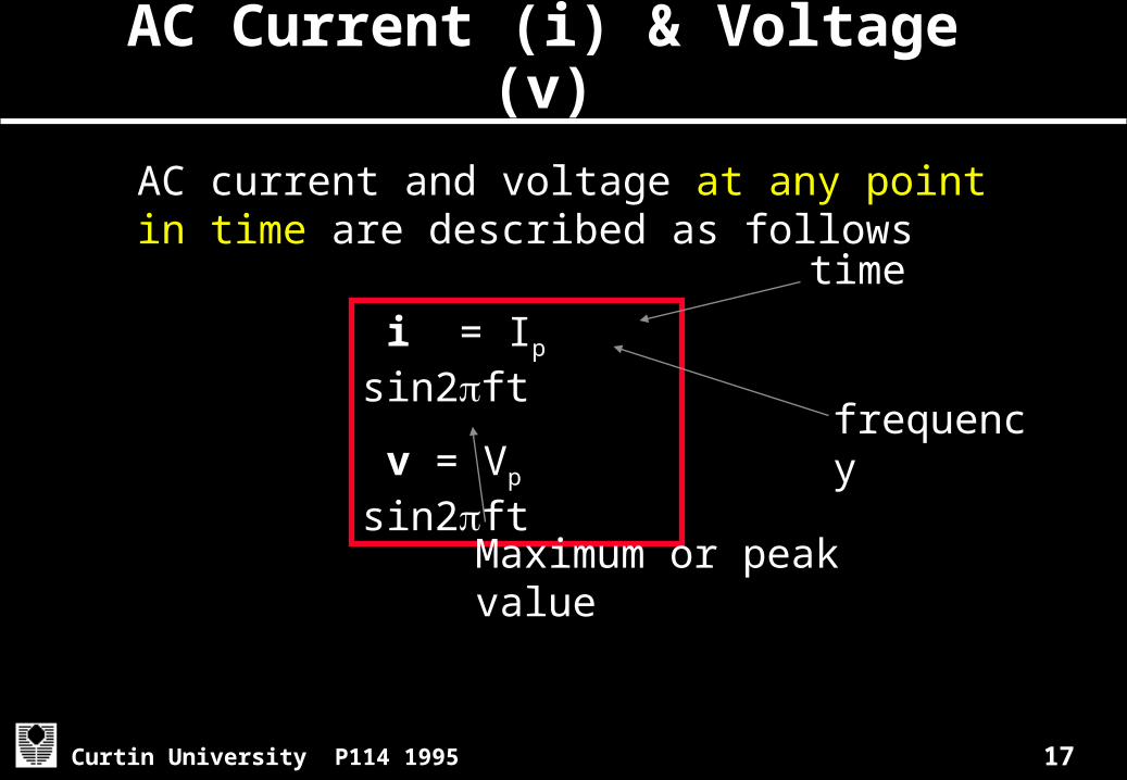
i = Ip sin2ft
v = Vp sin2ft
AC Current (i) & Voltage (v)
AC current and voltage at any point in time are described as follows
frequency
Maximum or peak value
time
18Curtin University P114 1995
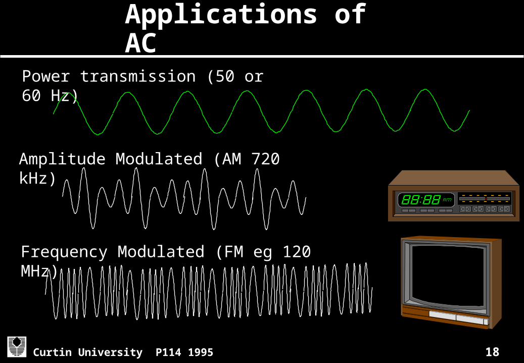
Applications of AC
Amplitude Modulated (AM 720 kHz)
Frequency Modulated (FM eg 120 MHz)
Power transmission (50 or 60 Hz)
19Curtin University P114 1995
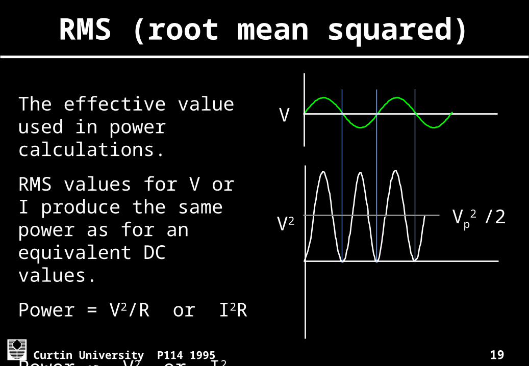
RMS (root mean squared)
The effective value used in power calculations.
RMS values for V or I produce the same power as for an equivalent DC values.
Power = V2/R or I2R
Power V2 or I2
V
Vp2
/2V2

20Curtin University P114 1995
RMS (root mean squared)
The voltage that produces Vp2
/2 equivalent .
Likewise for current
Vrms Vp
2
2Vp
20.707VP
irms ip2
0.707ip

21Curtin University P114 1995
ApplicationWhat are the peak voltages for AC power with Vrms or 240V and 120V respectively?
Vrms = 0.707 Vp or Vp = 1.41 Vrms
= 1.4 x 240 = 340 V
and for 120 V = 1.41 x 120 = 170 V
22Curtin University P114 1995
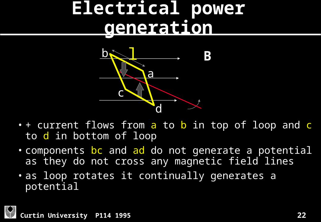
Electrical power generation
• + current flows from a to b in top of loop and c to d in bottom of loop
• components bc and ad do not generate a potential as they do not cross any magnetic field lines
• as loop rotates it continually generates a potential
Ba
b
dc
l
23Curtin University P114 1995
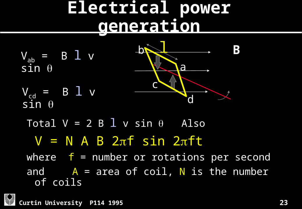
Electrical power generation
Total V = 2 B l v sin Also V = N A B 2f sin 2ftwhere f = number or rotations per secondand A = area of coil, N is the number of
coils
Ba
b
dc
lVab = B l v sin
Vcd = B l v sin
24Curtin University P114 1995
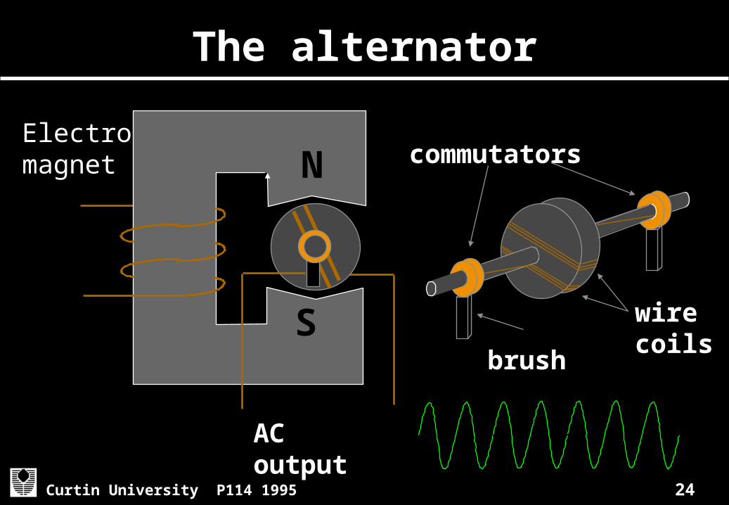
The alternator
N
S
AC output
Electromagnet
wire coils
commutators
brush
25Curtin University P114 1995
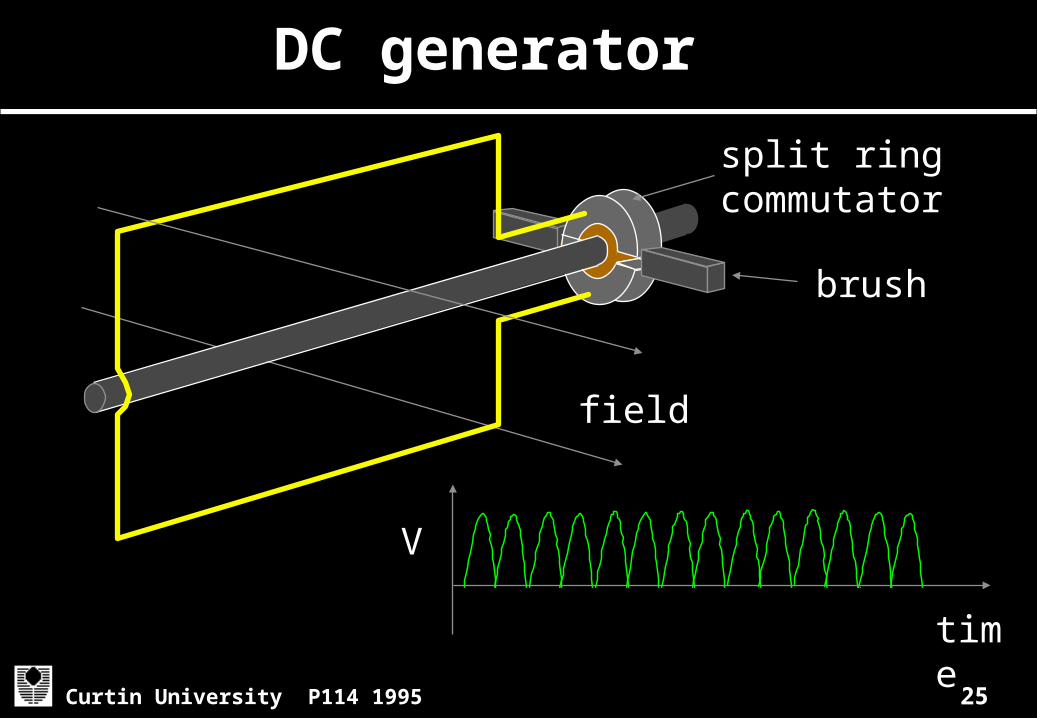
DC generator
brush
split ring commutator
field
time
V

26Curtin University P114 1995
Types of DC generators
A
+
N
S
-
Series
A
+
N
S
- +
A
N
S
-
Shunt Compound
i V i or i V is const

27Curtin University P114 1995
Transformers
A device for changing AC voltages
Vin
primary
Vout
Np =6 Ns =12
secondary
soft Fe laminated core
28Curtin University P114 1995
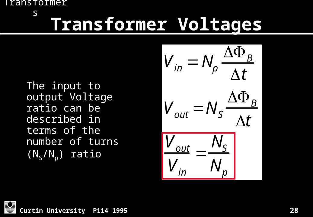
Transformer Voltages
The input to output Voltage ratio can be described in terms of the number of turns (NS/Np) ratio
V in NpB
t
Vout NSB
tVoutV in
NSNp
Transformers
29Curtin University P114 1995
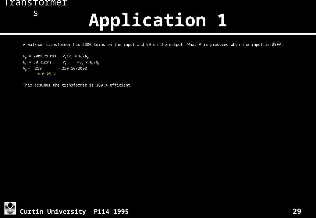
Application 1A walkman transformer has 2000 turns on the input and 50 on the output. What V is produced when the input is 250V.
Np = 2000 turns VS/Vp = NS/Np
NS = 50 turns VS =Vp x NS/Np
Vp = 250 = 250 50/2000
= 6.25 V
This assumes the transformer is 100 % efficient
Transformers
30Curtin University P114 1995
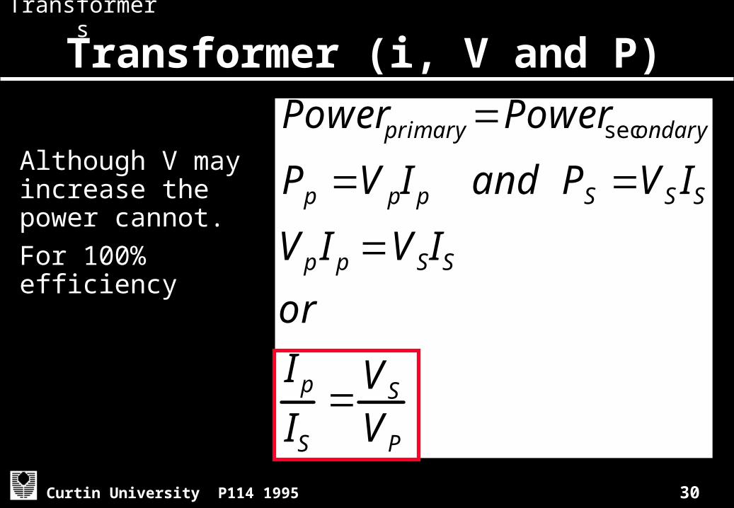
Transformer (i, V and P)
Although V may increase the power cannot.For 100% efficiency
Power primary Powersecondary
Pp V pIp and PS VS ISVp Ip VSISor
IpIS
VSVP
Transformers

31Curtin University P114 1995
Application 2
A step down transformer has turns ratio of 10:1 What is the input voltage and current if it transfers 150 W at 100V input?
Np/NS= 10 Vs =Vp x NS /Np
Vp = 100 = 100 x 1/10
Power = 150W = 10 V from P = V i i = P/V = 150/10 =15 A
Transformers

32Curtin University P114 1995
Adv and disadv of AC
ADVANTAGES• AC voltages can easily be increased
or decreased using transformers• easier to generate• reduced transmission losses• easier to control unwanted signalsDISADVANTAGES• Most small appliances require DC
33Curtin University P114 1995
Summary
• A changing magnetic field can produce an electrical potential in a conductor
• Moving a conductor through a magnetic field can produce an electrical potential in the conductor
• The direction of the induced current opposes the change in the magnetic field
• The advantages of alternating current over direct current
• P072 Q21.2 and 27.11, P21.3, 27.1 and 27.5

34Curtin University P114 1995
Challenge
• Which of the the following do you think is the most useful/important to society?
–Generator–Electric motor –Transformer
Briefly explain how it works and why you think it is the most important.