Dr. L. Christofi 1 Local & Metropolitan Area Networks ACOE322 Lecture 3 LAN types.
95
Dr. L. Christofi 1 Local & Metropolitan Area Networks ACOE322 Lecture 3 LAN types
-
Upload
hugo-mckinney -
Category
Documents
-
view
213 -
download
0
Transcript of Dr. L. Christofi 1 Local & Metropolitan Area Networks ACOE322 Lecture 3 LAN types.

Dr. L. Christofi 1
Local & Metropolitan Area Networks
ACOE322
Lecture 3LAN types

Dr. L. Christofi 2
0. LAN types• The types of LANs we will examine in this
section are as follows:
1. Ethernet (IEEE 802.3)
2. Token Ring (IEEE 802.5)
3. Fiber Distributed Data Interface (FDDI)
4. Wireless LANs (IEEE 802.11)

Dr. L. Christofi 3
1. Ethernet LANs
1.1 Traditional Ethernet (CSMA/CD)
1.2 10Mbps Ethernet
1.3 100Mbps Ethernet (Fast Ethernet - FE)
1.4 1000Mbps Ethernet (Gigabit Ethernet - GE)

Dr. L. Christofi 4
1.1 Ethernet (CSMA/CD)• The most widely used LANs today are based on Ethernet
and have been standardized by the IEEE 802.3 standards committee
• The Ethernet uses Carrier Sense Multiple Access with Collision Detection (CSMA/CD) as the access method
• Recall: —Layers specified by 802.3:
• Ethernet Physical Layer• Ethernet Medium Access (MAC) Sublayer
• Possible Topologies:— Bus— Branching non-rooted tree for large Ethernets

Dr. L. Christofi 5
Network Interface Card (NIC)• Each station on an Ethernet network (such as a PC,
workstation or printer) has its own NIC.
• The NIC fits inside the station and it is the interface between the station and the network.
• In most desktop computers, the NIC is an Ethernet card (10, 100 or 1000 Mbps) that is plugged into a slot on the computer motherboard.

Dr. L. Christofi 6
How does Ethernet work?• The NIC provides the station with a 6-byte
physical address, normally written in hex notation. This is the MAC address.
• Using MAC addresses to distinguish between machines, Ethernet transmits frames of data across baseband cables using CSMA/CD (IEEE 802.3)

Dr. L. Christofi 7
What is a MAC Address?• Media Access Control (MAC) Address is the
physical address of any device, e.g. a NIC in a computer on the network.
• The MAC address is 6-bytes long and has two parts of 3 bytes long.
The first 3 bytes specify the company that made the NIC
the second 3 bytes are the
serial number of the NIC
Example:
06 7A D3 01 BF 2C

Dr. L. Christofi 8
Minimal Bus Configuration
Host
Transceiver
TransceiverCable
Coaxial Cable
Terminator

Dr. L. Christofi 9
Typical Large-Scale Configuration
Host
Repeater
Ethernetsegment

Dr. L. Christofi 10
Ethernet Configuration

Dr. L. Christofi 11
Ethernet Physical Layer• Transceiver• Transceiver Cable
—4 Twisted Pairs—15 Pin Connectors
• Channel Logic—Manchester Phase Encoding—64-bit preamble for synchronization

Dr. L. Christofi 12
Ethernet Physical Configuration(for thick coaxial cable)• Segments of 500 meters maximum• Maximum total cable length of 1500 meters
between any two transceivers• Maximum of 2 repeaters in any path• Maximum of 100 transceivers per segment• Transceivers placed only at 2.5 meter
marks on cable

Dr. L. Christofi 13
Manchester Encoding
Recall:• 1 bit = high->low voltage signal
• 0 bit = low->high voltage signal
1 0 1 1 0 0Data stream
Encodedbit pattern
Ethernet uses Manchester Encoding scheme

Dr. L. Christofi 14
Ethernet Synchronization• 64-bit frame preamble used to synchronize
reception• 7 bytes of 10101010 followed by a byte
containing 10101011• Manchester encoded, the preamble appears
like a sine wave

Dr. L. Christofi 15
Ethernet Cabling Options• 10Base5: Thick Coax• 10Base2: Thin Coax (“cheapernet”)• 10Base-T: Twisted Pair• 10Base-F: Fiber optic• Each cabling option carries with it a
different set of physical layer constraints (e.g., max. segment size, nodes/segment, etc.)

Dr. L. Christofi 16
Ethernet: MAC Layer• Data encapsulation
—Frame Format—Addressing—Error Detection
• Link Management—CSMA/CD—Backoff Algorithm

Dr. L. Christofi 17
Ethernet Frame Format
FCS(4 bytes)
Destination(6 bytes)
Length (2 bytes)
Data(46-1500 bytes)
Pad
Source(6 bytes)
Multicast bit
64 Bytes < Ethernet frame size < 1518 Bytes

Dr. L. Christofi 18
Ethernet MAC Frame Address Field• Destination and Source Addresses:
—6 bytes each
• Two types of destination addresses—Physical address: Unique for each user—Multicast address: Group of users—First bit of address determines which type of
address is being used0 = physical address1 = multicast address

Dr. L. Christofi 19
Communicating Within the LAN
Unicast
Broadcast
Multicast

Dr. L. Christofi 20
IEEE 802.3 frame format (1)
64 Bytes* < Ethernet frame size < 1518 Bytes*
* Excluding Preamble and SFD

Dr. L. Christofi 21
IEEE 802.3 frame format (2)• Preamble: a 7-byte pattern of alternating 1s and 0s to
establish bit synchronization• Start frame delimiter (SFD):The sequence 10101011
indicates the actual start of the frame• Destination address (DA): specifies the station(s) for
which the frame is intended• Source address (SA): specifies the station that sent the
frame• Length/type: length of LLC data field in bytes or Ethernet
type field• LLC data: data unit supplied by LLC• Pad: bytes added to ensure that the frame is long enough
for proper CD operation. Filled when Length < 46.• Frame check sequence (FCS): a 4-byte CRC check,
based on all fields except preamble, SFD and FCS.

Dr. L. Christofi 22
CSMA/CD revisited• Recall:
—CSMA/CD is a “carrier sense” protocol.• If channel is idle, transmit immediately• If busy, wait until the channel becomes idle
—CSMA/CD can detect collections.• Abort transmission immediately if there is a collision• Try again later according to a backoff algorithm
• Carrier sense reduces the number of collisions
• Collision detection reduces the impact of collisions

Dr. L. Christofi 23
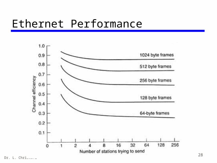
CSMA/CD inefficiency• Inefficiency of CSMA/CD
— When two frames collide, the medium remains unusable for the duration of transmission of both damaged frames
— For long frames, compared to propagation time, the amount of wasted capacity can be considerable.
— This waste can be reduced if a station continues to listen to the medium while transmitting

Dr. L. Christofi 24
CSMA/CD and Ethernet• Ethernet:
—Short end-to-end propagation delay—Broadcast channel
• Ethernet access protocol:—CSMA/CD with Binary Exponential Backoff
Algorithm

Dr. L. Christofi 25
Ethernet Backoff Algorithm:Binary Exponential Backoff• If collision,
—Choose one slot randomly from 2k slots, where k is the number of collisions the frame has suffered.
—One contention slot length = 2 x end-to-end propagation delay
This algorithm can adapt to changes in network
load.

Dr. L. Christofi 26
Binary Exponential Backoff (cont’d)
slot length = 2 x end-to-end delay = 15 s
A B
@ t=0ms: Assume A and B collide (kA = kB = 1)A, B choose randomly from 21 slots:
[0,1]Assume A chooses 1, B chooses 1
@ t=30ms: A and B collide (kA = kB = 2)A, B choose randomly from 22 slots:
[0,3]Assume A chooses 2, B chooses 0
@ t=45ms: B transmits successfully
@ t=75ms: A transmits successfully

Dr. L. Christofi 27
Binary Exponential Backoff (cont’d)
• In Ethernet,—Binary exponential backoff will allow a maximum
of 15 retransmission attempts—If 16 backoffs occur, the transmission of the
frame is considered a failure.
Dr. L. Christofi 28
Ethernet Performance

Dr. L. Christofi 29
Ethernet Features and Advantages• Passive interface:
— No active element• Broadcast:
— All users can listen• Distributed control:
— Each user makes own decision
SimpleReliable
Easy to reconfigure

Dr. L. Christofi 30
Ethernet Disadvantages
• Lack of priority levels
• Cannot perform real-time communication
• Security issues

Dr. L. Christofi 31
Ethernet Switching• Recent development: Connect many
Ethernet segments or subnets through an “Ethernet switch”
to segment 1
to segment 2to segment 3
to segment 4
Dr. L. Christofi 32
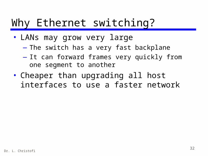
Why Ethernet switching?• LANs may grow very large
—The switch has a very fast backplane—It can forward frames very quickly from one
segment to another
• Cheaper than upgrading all host interfaces to use a faster network

Dr. L. Christofi 33
1.2 10Mbps Ethernet• Physical configurations
—10BASE5—10BASE2—10BASE-T—10BASE-F
Note: 10 refers to data rate in Mbps, BASE=Baseband5= 50Ω coaxial cable2= thinner 50Ω coaxial cableT= Unshielded twisted pair cableF = Fiber Optic cable

Dr. L. Christofi 34
10BASE-T medium specification• Unshielded twisted pair (UTP) cables are found prewired in
office buildings as excess telephone cable and can be used for LANs
• 10BASE-T defines a star topology• Stations attach to a multiport repeater via a point-to-point link• The link consists of two UTPs.• The data rate is 10Mbps using Manchester encoding• Length of link is limited to 100m• If an optical cable is used, the maximum length is 500m.• A 10BASE-T system can be mixed with 10BASE5 and 10BASE2
systems via repeaters• Maximum transmission path between any two stations is 5
segments and 4 repeater sets.—A segment is a point-to-point link or a coaxial cable—The maximum number of coaxial cable segments in a path
is 3.

Dr. L. Christofi 35
10BASE-F medium specification • Added to IEEE 802.3 in 1993• Advantages of the distance and transmission on
optical fiber• 10BASE-FP (passive): passive-star topology for
stations/repeaters with up to 1 km per segment; makes synchronous retransmission
• 10BASE-FL (link): a point-to-point link for connecting stations/repeaters at up to 2 km; asynchronous signaling; any timing distortions are propagated through a series of repeaters
• 10BASE-FB (backbone): a point-to-point link for connecting repeaters at up to 2 km; a cascade up to 15 repeaters in sequence to activate greater length.

Dr. L. Christofi 36
High speed LANsStandard Ethernet LANs and MANs (up to 10Mbps) are based on one copper wire.
This is OK for low speed and short distances but not suitable for high speed and longer distances -> use fiber instead.
Fast and Gigabit Ethernet
FDDI (Fiber Distributed Data Interface)
HIPPI (High Performance Parallel Interface)

Dr. L. Christofi 37
1.3 Fast Ethernet• Operates at 100 Mbps• Standardized in IEEE 802.3 as 100BASE-T and 100BASE-F • Basic idea behind Fast Ethernet (FE) was simple: keep
all the old packet format, interfaces, procedural rules and cables, but just reduce the bit time from 100ns to 10ns.

Dr. L. Christofi 38
IEEE 802.3 100BASE-T Physical Layer Medium Alternatives

Dr. L. Christofi 39
Configuration and operation• In its simplest form, a 100BASE-T network
is configured in a star-wire topology, with all stations connected directly to a central point (multiport repeater).
• The repeater is responsible for detecting collisions, not the attached devices. Its functions are:—A valid signal appearing on any input is repeated
on all output links—If two inputs occur at the same time, a jam signal
is transmitted on all links

Dr. L. Christofi 40
Collision domain• Used to define a single CSMA/CD network• This means that if two stations transmit at the same
time, a collision will occur.—Stations separated by a simple multiport repeater are
within the same collision domain—Stations separated by a bridge are in different collision
domains
Bridged EthernetSeparates collision domains

Dr. L. Christofi 41
Example: 100-Mbps Ethernet Backbone Strategy

Dr. L. Christofi 42
1.4 Gigabit Ethernet (GE)• Operates at 1Gbps• Same strategy as FE• CSMA/CD protocol and frame format, same as in 10Mbps
and 100Mbps Ethernet• Compatible with 100BASE-T and 10BASE-T

Dr. L. Christofi 43
Protocol architecture• The MAC layer is an enhanced version of the basic
802.3 MAC algorithm• A separate Gigabit Medium-Independent Interface
(GMII) is optional except for the UTP

Dr. L. Christofi 44
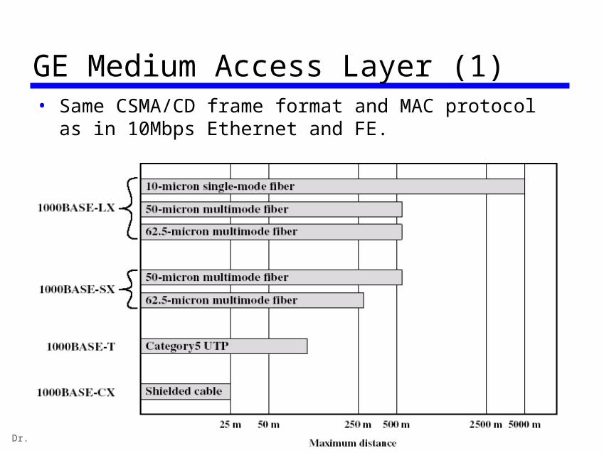
GE Physical layer• 1000BASE-LX
—Long-wavelength option—Supports duplex links up up to 550m for multimode
fiber or up to 5km for single mode fiber• 1000BASE-SX
—Short-wavelength—Supports duplex links up to 550m for multimode fiber
• 1000BASE-CX—Supports 1Gbps among devices located within a single
room using copper jumpers (STP cable up to 25m long)• 1000BASE-T
—Makes use of 4 pairs CAT5 UTP cables to support devices over a range of up to 100m
Dr. L. Christofi 45
GE Medium Access Layer (1)• Same CSMA/CD frame format and MAC protocol as in
10Mbps Ethernet and FE.

Dr. L. Christofi 46
GE Medium Access Layer (2)• For hub operation (half duplex) there are two
enhancements to the basic CSMA/CD scheme—Carrier extension
• Appends a set of special symbols to the end of short MAC frames so that the resulting block is at least 4096 bit times in duration, up from the minimum 512 bit times imposed at standard Ethernet and FE.
—Frame bursting• Allows for multiple short frames to be transmitted
consequentially without releasing control for CSMA/CD between frames
• Avoid the overhead of carrier extension when a single station has a number of small frames ready to send

Dr. L. Christofi 47
2. Token Ring• Widely used although not as popular as
Ethernet
• Based on IEEE 802.5 standard
• We will now examine the Medium Access Layer and then the Physical layer aspects of this specification

Dr. L. Christofi 48
IEEE 802.5 Token Ring Medium Access Control

Dr. L. Christofi 49
Token ring operation• Based on the use of a small frame, called a
token, that circulates when all stations are idle• Whenever a station wishes to send a frame, it
first waits for the token• On receipt of the token, it initiates
transmission of the frame, which includes the address of the intended recipient at its header
• The frame is repeated by all stations in the ring, until it circulates back to the initiating station, where it is removed
• The intended recipient also retains a copy of the frame

Dr. L. Christofi 50
Token Passing (1)
Token is traveling along the ringStation A captures the token and
sends its data to D

Dr. L. Christofi 51
Token Passing (2)
Station D copies the frame and sends the data back to
the ring
Station A receives the frame and releases the token

Dr. L. Christofi 52
MAC frame (1)

Dr. L. Christofi 53
MAC frame (2)• The MAC frame consists of the following fields:
—Starting Delimiter (SD): Indicates start of frame—Access Control (AC): Contains info for priority, reservation
variables and monitor bit—Frame Control (FC): indicates if this is an LLC data frame—Destination address (DA): As with 802.3—Source address (SA): As with 802.3—Data Unit (DU): Contains LLC data unit—Frame Check Sequence (FCS): As with 802.3—End Delimiter (ED): Contains the error detection bit (E),
which is set if any repeater detects an error and the Intermediate (I) bit, which is used to indicate that this is a frame other than the final one of a multiple frame transmission
—Frame Status (FS): Contains the address recognized (A) and frame Copied (C) bits.

Dr. L. Christofi 54
Token maintenance• To overcome error conditions, one station is designated
as the active monitor—Periodically issues an Active-Monitor-Present control frame
to assure other stations that there is an active monitor on the ring
—To detect a lost-token condition, the monitor uses a valid-frame timer that is greater than the time required to traverse the ring.
—The timer is reset every valid token or data frame— If the time expires, the monitor issues a priority 0 token— If it sees a persistently circulating data frame with the
monitor bit set, it absorbs it and transmits a priority 0 token—No token should circulate completely around the ring at a
constant nonzero priority level— If the active monitor detects another active monitor, it
immediately goes into standby status.

Dr. L. Christofi 55
Dedicated Token Ring (DTR)• A Ring can be configured in a star topology by use of a
hub, or concentrator.• The token-passing algorithm can be used so that the
ring capacity is still shared and access control is determined by the token.
• It is also possible to have the central hub function as a switch with the connection between each station as a full-duplex point-to-point link.
• The DTR specification defines the use of stations and concentrators in the switched mode.
• The DTR concentrator acts as a frame-level relay rather than a bit-level repeater: each link from concentrator to station is a dedicated full-duplex link with immediate access possible (token passing is not used).

Dr. L. Christofi 56
Example DTR configuration (1)

Dr. L. Christofi 57
Example DTR configuration (2)• A DTR switch consists of C-ports and a data transfer
unit (DTU). A C-port may operate in 2 modes:—Transmit immediate protocol (TXI)
• Full duplex mode of transmission• C-port or device does not need the capture of a token to
transmit frames and can transmit frames at any time
—Token-passing protocol (TPP)• Classic IEEE802.5 protocol, that allows integration of
classic token-passing stations and ring-concentrators into a DTR configuration
• C-port behaves as if it is part of a ring and passes the token accordingly
• The DTU is the switching mechanism that connects the C-ports within a DTR switch

Dr. L. Christofi 58
Token ring trade-offs• Advantage
—Flexible control over access that it provides
• Disadvantage—The requirement for token maintenance
• Loss of token prevents further utilization of the ring• Duplication of the token cal also disrupt ring
operation• One station must be selected as monitor to ensure
that exactly one token is on the ring and to reinsert a free token if necessary

Dr. L. Christofi 59
IEEE 802.5 Token Ring Physical layer• The standard imposes a maximum frame
size of —4.550 bytes at 4Mbps, and —18.200 bytes for 16Mbps and 100Mbps—This compares with a maximum frame size of
1518 bytes for IEEE 802.3 LANs
• At 4Mbps and 16Mbps, token-passing access control or switched DTR technique can be used
• At 100Mbps, the DTR technique is mandatory.

Dr. L. Christofi 60
IEEE 802.5 physical layer medium alternatives

Dr. L. Christofi 61
3. FDDI (Fiber Distributed Data Interface)• This is a 100Mbps token Ring LAN/MAN specification• Uses Optical Fiber cabling• High reliability (dual rings)• Immune to interference• Standardized by ANSI
Distances of up to 200 km Up to 1000 hosts attached

Dr. L. Christofi 62
Fiber Distributed Data Interface (FDDI) Standards
• ANSI ASC X3T9.5 Standard Committee
• ISO 9314 Standard Series
• FDDI serves both LAN and MAN
• FDDI – a token ring scheme, similar to the IEEE 802.5 specification
• FDDI was designed to accommodate better the rate of 100 Mbps
• Some differences are at the MAC layer and at the physical layer.

Dr. L. Christofi 63
FDDI operation • FDDI protocols are closely modelled to the 802.5
protocols. – To transmit data, a station must first capture the
token. – Then it transmits a frame and removes it when it
comes around again.
• The difference between FDDI and 802.5 is that in 802.5 a station may not generate a new token until its frame has gone all the way around and come back.
– With FDDI, the amount of time wasted waiting for the frame is substantial due to the large distances and large number of station involved. For this reason, a station is allowed to put a new token back onto the ring as soon as it has finished transmitting its frames.

Dr. L. Christofi 64
FDDI MAC frame format
Similar to Token Ring

Dr. L. Christofi 65
FDDI MAC Frame • Preamble: synchronizes the frame with each station’s
clock• Starting Delimiter (SD): Indicates the start of frame• Frame Control (FC): Indicates if this is a synchronous
or asynchronous frame• Destination address (DA): specifies the station(s) for
which the frame is intended• Source address (SA): specifies the station that sent
the frame• Information: Contains LLC data unit or control info• Frame Check Sequence (FCS): 4-byte CRC• End Delimiter (ED): marks the end of the frame• Frame Status (FS): Contains the error detected (E),
address recognized (A) and frame copied (F) indicators

Dr. L. Christofi 66
FDDI token frame • Preamble: synchronizes the frame with
each station’s clock• Starting Delimiter (SD): Indicates the
start of frame• Frame Control (FC): has the bit pattern
1000 0000 or 1100 0000 to indicate that this is a token
• End Delimiter (ED): marks the end of the token frame

Dr. L. Christofi 67
Comparison of FDDI and IEEE 802.5 Token Ring (1)

Dr. L. Christofi 68
Comparison of FDDI and IEEE 802.5 Token Ring (2)• Quite similar• The FDDI frame includes a preamble to aid
in clocking, which is more demanding at the higher data rate
• Both 2-byte and 4-byte addresses are allowed in the same network with FDDI—More flexible than the scheme used on all 802
standards
• Some differences in control bits—FDDI does not include priority and reservation bits—Capacity allocation is handled in a different way

Dr. L. Christofi 69
FDDI MAC Protocol
• Fundamentally, the same as IEEE 802.5 Token Ring MAC Protocol but with two differences:
• First Difference—In FDDI, a station waiting for a token seizes the
token by aborting (failing to repeat) the token transmission as soon as the token frame is recognized. The station begins transmitting one or more data frames. No flipping a bit to convert a token [high data rate].
• Second Difference—A station that has been transmitting data frames
releases a new token as soon as it completes data frame transmission, even if it has not begun to receive its own transmission.
Dr. L. Christofi 70
FDDI Token Ring Operation (1)

Dr. L. Christofi 71
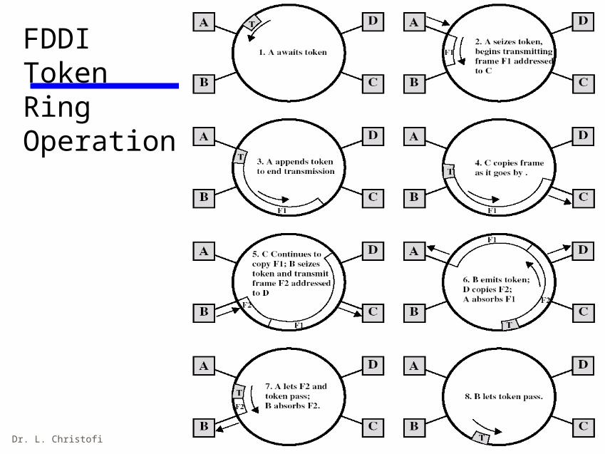
FDDI Token Ring Operation (2)• With reference to the previous slide:
—After station A has seized the token, it transmits frame F1 and immediately transmits a new token.
—F1 is addressed to station C, which occupies it as it circulates past.
—The frame eventually returns to A, which is absorbed.
—Meanwhile, B seizes the token issued by A and transmits F2 followed by a token
—This action could be repeated any number of times, so that at any one time there may be multiple frames circulating the ring
—Each station is responsible for absorbing its own frames based on the source address field

Dr. L. Christofi 72
FDDI Dual Ring Operation
(a) FDDI consists of 2 counter-rotating rings.
(b) In the event of failure of both rings at one point, the two rings can be joined together to form a single long ring

Dr. L. Christofi 73
FDDI Physical Layer specifications• The FDDI standard specifies a ring topology
operation at 100Mbps

Dr. L. Christofi 74
4. Wireless LANs• Wireless LANs dispense with cables and use radio or
infrared frequencies to transmit signals through the air.
• WLANs are growing in popularity because they eliminate cabling and facilitate network access from a variety of locations and for mobile workers.
• The most common wireless networking standard is IEEE 802.11, often called Wireless Ethernet or Wireless LAN.

Dr. L. Christofi 75
Wireless Ethernet (IEEE 802.11) Key Points• The principal technologies used for wireless LANS
are — infrared — spread spectrum — narrowband microwave.
• The IEEE 802.11 standard defines a set of services and physical layer options for wireless LANs.
• The IEEE 802.11 services include managing associations, delivering data, and security.
• The IEEE 802.11 physical layer includes infrared and spread spectrum and covers a range of data rates.
Dr. L. Christofi 76
Technology• Infrared (IR) LANs: Individual cell of IR
LAN limited to single room.— IR light does not penetrate opaque walls.
• Spread spectrum LANs: Mostly operate in ISM (industrial, scientific, and medical) bands.—No Federal Communications Commission (FCC)
licensing is required in USA.
• Narrowband microwave: Microwave frequencies but not use spread spectrum—Some require FCC licensing

Dr. L. Christofi 77
Infrared Wireless LANs• Less flexible than IEEE 802.11 WLANs because, as with
TV remote controls that are also infrared based, they require line of sight to work.
• Infrared Hubs and NICs are usually mounted in fixed positions to ensure they will hit their targets.
• The main advantage of infrared WLANs is reduced wiring.
• A new version, called diffuse infrared, operates without a direct line of sight by bouncing the infrared signal off of walls, but is only able to operate within a single room and at distances of only about 50-75 feet.

Dr. L. Christofi 78
Terminology• Access Point (AP): Provides access to the
distribution system via the wireless medium.
• Basic Service Set (BSS): A set of stations controlled by a single coordination function.
• Coordination function: Determines when a station is operating.
• Distribution System (DS): Interconnection between BSS and LANs to form an ESS.
• Extended Service Set (ESS): A set of interconnected BSSs and LANs.
• MPDU / MSDU: MAC Protocol/Service Data unit.

Dr. L. Christofi 79
Wireless LAN Topology
• WLAN topologies are the same as on Ethernet: physical star, logical bus.
• Wireless LAN devices use the same radio frequencies, so they must take turns using the network.
• Instead of hubs, WLANs use devices called access points (AP). Maximum transmission range is about 100-500 feet. Usually a set of APs are installed making wireless access possible in several areas in a building or corporate campus.
• Each WLAN computer uses an NIC that transmits radio signals to the AP.
• Because of the ease of access, security is a potential problem, so IEEE 802.11 uses 40-bit data encryption to prevent eavesdropping.

Dr. L. Christofi 80
Access Point

Dr. L. Christofi 81
Wireless LAN Applications (1)
• (1) LAN Extension:— Saves installation of LAN cabling.— Eases relocation and other modifications to network
structure.
• However, increasing reliance on twisted pair cabling for LANs as newer buildings are prewired with Cat 5.
• Wireless LAN to replace wired LANs has not happened.
• Buildings with large open areas: role for the wireless LAN (Airports, Manufacturing plants, stock exchange trading floors, warehouses).

Dr. L. Christofi 82
Single Cell Wireless LAN

Dr. L. Christofi 83
Multi-Cell Wireless LAN

Dr. L. Christofi 84
Wireless LAN Applications (2)
• (2) Cross-Building interconnect:—Connect LANs in nearby buildings.—Point-to-point wireless link.—Connect bridges or routers.
• (3) Nomadic Access:—Link between LAN hub and mobile data terminal
like a Laptop or notepad computer.—Also useful in extended environment such as
campus or cluster of buildings.—Users move around with portable computers.—May wish access to servers on wired LAN.

Dr. L. Christofi 85
Infrastructure Wireless LAN

Dr. L. Christofi 86
Wireless LAN Applications (3)
• (4) Ad Hoc Networking (=special purpose networking)—Point-to-point wireless link, Peer-to-peer
network.—Set up temporarily to meet some immediate
need.—E.g. group of employees, each with laptop or
palmtop, in business or classroom meeting.—Network for duration of meeting.

Dr. L. Christofi 87
Ad Hoc Wireless LAN

Dr. L. Christofi 88
Wireless LAN Requirements (1)• Throughput: MAC should make efficient use of
the wireless medium to maximise capacity.
• Number of nodes: Support hundreds of nodes.
• Connection to backbone LAN: Use control modules to connect to both types of LANs.
• Service area: Diameter of 100 to 300m
• Battery power consumption: Wireless LAN have features to reduce power consumption.

Dr. L. Christofi 89
Wireless LAN Requirements (2)• Transmission robustness and security:
The design must permit reliable transmission in noisy environment and protection from eavesdropping.
• Collocated network operation: Two or more wireless LANs in same area.
• License-free operation.
• Handoff/Roaming: Mobile stations can move.
• Dynamic configuration: Addition, deletion, and relocation of end systems without disruption to users.

Dr. L. Christofi 90
Advantages / Disadvantages
• Extremely high data rates.• Use ceiling reflection to cover entire room.• Does not penetrate walls or other opaque objects.• More easily secured against eavesdropping than
microwave.• Inexpensive and simple
• Background radiation• Sunlight, indoor lighting• Noise, requiring higher power and limiting range• Power limited by concerns of eye safety and power
consumption.

Dr. L. Christofi 91
MAC Frame• Frame Control: Control management or data.• Duration/Connection ID: Time the channel is allocated
in μs for a transmission of a frame.• Addresses: Source, destination, transmitting station and
receiving station.• Sequence control: Contains data fragmentation and
reassembly and the number of frames.• Frame body: Contains an MSDU.• Frame Check Sequence: CRC.

Dr. L. Christofi 92
IEEE 802.11 Services
Service Provider Category
Association Distribution system MSDU delivery
Authentication Station LAN access and security
Deauthentication
Station LAN access and security
Dissassociation Distribution system MSDU delivery
Distribution Distribution system MSDU delivery
Integration Distribution system MSDU delivery
MSDU delivery Station MSDU delivery
Privacy Station LAN access and security
Reassocation Distribution system MSDU delivery

Dr. L. Christofi 93
IEEE 802.11xx standards
• IEEE 802.11a: 5GHz, Orthogonal FDM, data rates of 6-54Mbps.
• IEEE 802.11b: 5.5Mbps and 11Mbps.
• IEEE 802.11g: Higher speed extension of 802.11b 20 Mbps.
• IEEE 802.16: Wi-Fi – Starbucks Wi-Fi spot 100 Mbps.
• IEEE 802.21 WiMax, over 100 Mbps, 50km range, broadband speeds.

Dr. L. Christofi 94
Review Questions• List and briefly define the four
application areas of wireless LANs.• List and briefly define the key
requirements for wireless LANs.• What are some key advantages and
disadvantages of wireless LANs.• List and define some of the IEEE 802.11
services.• List and describe the IEEE 802.11xx
family.

Dr. L. Christofi 95
• W. Stalling, Local and Metropolitan Area Networks, 6th edition, Prentice Hall, 2000
References
• F. Halsall, Data Communications, Computer Networks and Open Systems, 4th edition, Addison Wesley, 1995
• B.A. Forouzan, Data Communications and Networking, 3rd edition, McGraw-Hill, 2004
• W. Stallings, Data and Computer Communications, 7th edition, Prentice Hall, 2004