Dr. Charles Kim - MWFTR - Learning Environment. Charles Kim Department of ... a8-bit processor...
37
1 EECE416 :Microcomputer Fundamentals and Design X86 Assembly Programming Part 1 Dr. Charles Kim Department of Electrical and Computer Engineering Howard University www.MWFTR.com
Transcript of Dr. Charles Kim - MWFTR - Learning Environment. Charles Kim Department of ... a8-bit processor...

1
EECE416 :Microcomputer Fundamentals and Design
X86 Assembly Programming
Part 1
Dr. Charles KimDepartment of Electrical and Computer Engineering
Howard University
www.MWFTR.com
ckim
Typewritten Text
EECE416 Electrical and Computer Engineering Howard University Instructor: Dr. Charles Kim www.mwftr.com/416F15.html
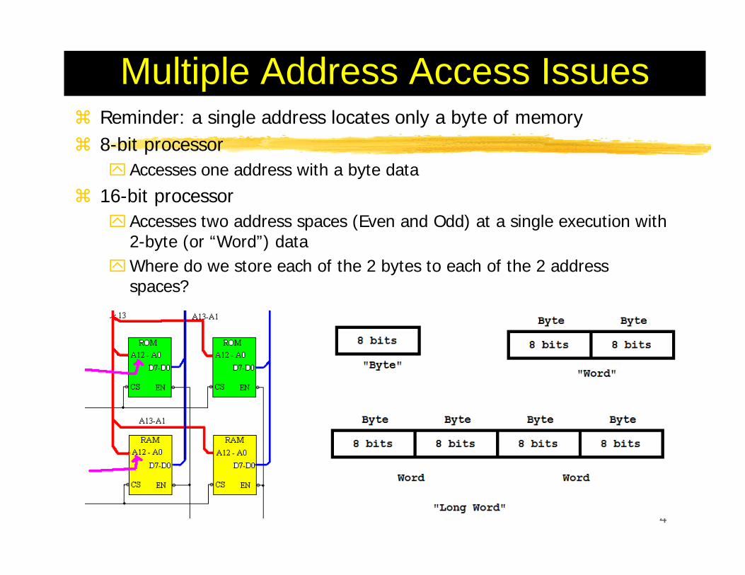
Multiple Address Access IssuesReminder: a single address locates only a byte of memory8-bit processor
Accesses one address with a byte data
16-bit processorAccesses two address spaces (Even and Odd) at a single execution with 2-byte (or “Word”) dataWhere do we store each of the 2 bytes to each of the 2 address spaces?
4

5
Big-Endian vs. Little-EndianBig-Endian: Words are stored with the lower 8- bits (“Lower Byte”) in the higher of the two storage locations (“Addresses”): Motorola
“Big guy (“Upper Byte”) ends at lower address”Little- Endian: Lower-order byte stored in the lowest address: Intel 80x86 family
Little guys (“Lower Byte”) ends at lower address”

“Endianness”Endian or Endian-Architecture
how multi-byte data is represented by a computer system and is dictated by the CPU architecture of the systemNot all computer systems are designed with the same endian architectureIssues with software and interface
6

Endian-Neutral Approaches
ConversionByte SwapNetwork I/O Macro
“Endian Neutral”: allowing the code to be ported easily between processors of different Endian-architectures, and without rewriting any code. Endian-neutral software is developed by identifying system memory and external data interfaces, and using Endian-neutral coding practices to implement the interfaces.
7

HOMEWORKTechnical Report on “Endian-Neutral Approaches”
What? Why? How? 2 - 3 pages; 1” margin all sides; 11 pt; Times New Roman; No cover page (Title and your name at the top, and start in the first page); single space; single column; again the importance of the first paragraph. No figure, no photo, text only.Submission Due: Hardcopy + Softcopy by 5:00pm Date: Tuesday Oct 6
8

9
x86 Architecture First x86 Family member: 8086 ( 8088). 1978
Cf. 4004 8080 8085
808616-bit registers, external data bus20-bit addressing (1MB address space)Segmentation : 64KB⌧Why? Internal 16-bit
register cannot hold 20-bit address

10
X86 Modes of OperationProtected Mode (from i286)
Native State of the Processor in which all instructions and features are availablePrograms a re given separate memory areas (“Segments”), and the processor prevents programs from referencing memory outside their assigned segments.
Real Address ModeA few extra features available for this mode by which direct access to system memory and hardware devices is possible (Windows 98, and MS-DOS)Programs running in real-address mode can cause the OS crash
Virtual-8086 ModeWhile in Protected Mode, processor can directly execute real-address mode software such as MS-DOS programs in a safe multitasking environment [Windows XP]
System Management ModePower Management and System SecurityCustomized by manufacturers for a particular system setup

11
x86 Memory ManagementReal Address Mode
1 MB Memory can be accessed 0x000000 –0x0FFFFF [Details to come]Processor runs one program at a timeApplication programs are allowed to access any memory location including that is linked directly to system hardwareMS-DOS and Windows95 and 98
Protected Mode [Details to come]Access to a total of 4GB MemoryMultiple programs run at the same time – own reserved memory areaWindows and Linux
12
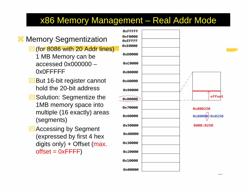
x86 Memory Management – Real Addr Mode
Memory Segmentization(for 8086 with 20 Addr lines) 1 MB Memory can be accessed 0x000000 –0x0FFFFF But 16-bit register cannot hold the 20-bit addressSolution: Segmentize the 1MB memory space into multiple (16 exactly) areas (segments)Accessing by Segment (expressed by first 4 hex digits only) + Offset (max. offset = 0xFFFF)

13
x86 Memory Management – Real Addr Mode
20-bit address calculation16-bit segment value16-bit offset valueMemory address = (16-bit Segvalue) *0x10 + (16-bit Offset)16-bit segment value is placed in one of the segment registers: ⌧CS: Code seg register⌧DS: data seg register⌧SS: Stack seg register⌧ES, FS, GS, etc

14
x86 Memory Management –Protected ModePowerful native modeIn Microsoft Assembler (MASM)
“Flat (Segment) Mode” is appropriate for protected mode programmingJust 1 32-bit address register is enough (for up to 4 GB Memory space)Actual address location calculation is done in the background

15
x86 Architecture80286
“Protected Mode” first introduced Segment register contents as selector or pointer
⌧24-bit base address 16MB memory size
8038632-bit registers for operands and addressing( 4GB space)Lower half of 32 bits is equivalent to 16 bits of earlier generations [Backward (upward) compatibility with 16-bit registers]Some new instructions was added (like bit manipulation)Max 4GB segmentation of physical spaceNew Parallel Processing Stages introduced: Bus Interface Unit, Code Prefetch Unit, Instruction Decode Unit, Execution Unit, Segment Unit, Paging Unit

16
Overview of Basic Execution
Set of resources for Executing instructions and for Storing code, data, and state informationResources:
8 General data registers6 Segment registersStatus and control registers
Holding the following items (for all):Operands for logical and arithmetic operationsOperands for address calculationsMemory pointers

17
General-Purpose Data RegistersE??: “Extended” or “32-bit”??X: “16-bit”Primaries
EAX (accumulator for operands and results data) EBX (Pointer to data in Segment) ECX (Counter)EDX (for I/O pointer)
SecondariesEBP (base pointer to data on the stack in DS segment) ESI (Source pointer) EDI (data pointer) for string instructionsESP (Stack pointer)holds the stack pointer (restricted use)ESP points to the top item on the stack and the EBP points to the "previous" top of the stack before the function was called.

EFLAG Register32-bit register
Initial state: 00000002HContains a group of status flags (S), a control flag (C), and a group of system flags (X)

Status Flags

Control Flag (DF)
DF (Direction Flag)The direction flag controls the string instructions (MOVS, CMPS, SCAS, LODS, and STOS). DF=1 string instructions to auto-decrement (that is, to process strings from high addresses to low addresses). DF=0 string instructions to auto-increment (process strings from low addresses to high addresses).STD Set DF flagCLD Clear DF flag

System Flags

MASM Screen Capture
22

Notational ConventionsLittle Endian MachineBit and Byte Oder
Smaller address at the bottom of figureAddress increases toward topBit positions numbered from right to leftthe bytes of a word are numbered starting from the least significant byte
23

How does a simple code look?
24

Assembly Language FundamentalsInteger Constants
[{+/-}] digits [radix]Radix⌧H hexadecimal⌧q/o Octal⌧D Decimal {Default}⌧b Binary⌧Example: *Note: Hex constant beginning with a letter must
have a leading 0
25

Assembly Language FundamentalsCharacter Constants
A single character enclosed in single or double quotes⌧“A” ⌧“d”
MASM stores the value in memory as the character’s binary ASCII code
String ConstantsA sequence of characters (including spaces) enclosed in single or double quotes⌧‘ABC’⌧“Good night, Gracie”⌧‘Say “Good night,” Gracie’
26
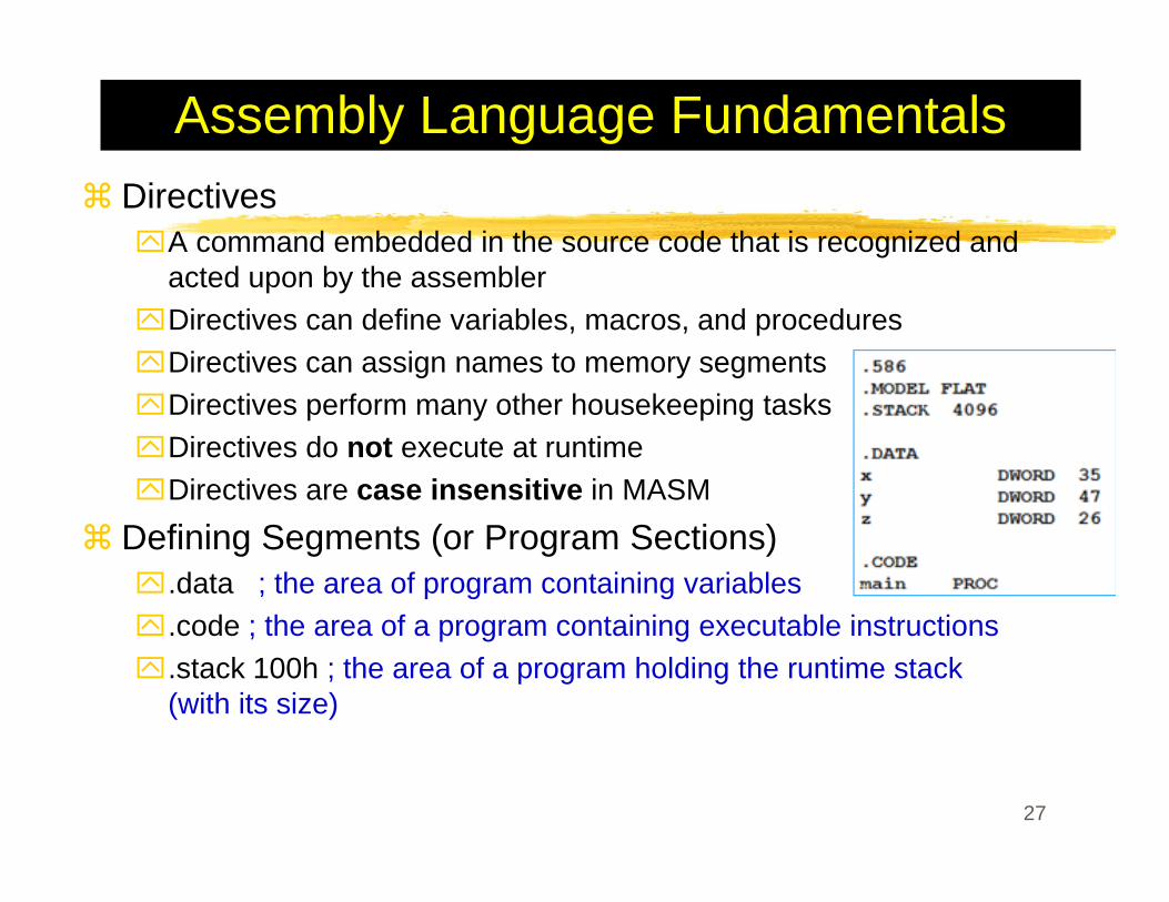
Assembly Language FundamentalsDirectives
A command embedded in the source code that is recognized and acted upon by the assemblerDirectives can define variables, macros, and proceduresDirectives can assign names to memory segmentsDirectives perform many other housekeeping tasksDirectives do not execute at runtimeDirectives are case insensitive in MASM
Defining Segments (or Program Sections) .data ; the area of program containing variables.code ; the area of a program containing executable instructions.stack 100h ; the area of a program holding the runtime stack (with its size)
27

28
Assembly Language FundamentalsInstruction: “A statement that becomes executable when a program is assembled” – Instrcutions are translated by the assembler into machine language bytes, which are loaded and executed by the CPU at runtimeInstruction Format
Label, Instructional mnemonic, argument1, argument2, argument3Label: Identifier (followed by a colon)Mnemonic: a reserved name for a class of instruction opcodes which have the same functionOperands (arguments): The operands argument1, argument2, and argument3 are optional. ⌧ 0 to 3 operands⌧ 2 types of form: literals (i.e., numer) or identifiers for data items.
When two operands are present in an arithmetic or logical instruction⌧ the right operand is the source (src) and⌧ the left operand, the destination (dst).
Example: Count DWORD 100 ; data labelLOADREG: MOV EAX, SUBTOTAL;code label mnemonic dst, src

29
Assembly Language FundamentalsInstruction Mnemonic: a short word that identifies an instructionExample
Example

30
Assembly Language FundamentalsCommentsSingle Line Comments (;)
; This line is a commentBlock Comments: Begin with the COMMENT directive and a user-specified symbol

Assembly Language FundamentalsNOP (No Operation) Instruction
Takes up 1 byte of program storage Does not do any workUse when to align code to even-addressed boundaries (which, in x86, loads data more quickly.)
31

Assembly Language Fundamentals - ExamplesAdding and Subtracting IntegersTITLE directiveLine commentINCLUDE directive
.code directivePROC directive – start
CALL a procedureExit --- halt to program (Not a MASM keyword, but of Irvine32.inc)ENDP directive – endEND directive – last line to be assembledOutput (DumpRegs)
32
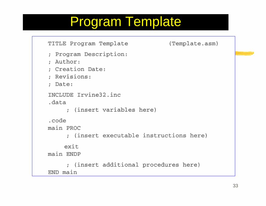
Program Template
33

Assembling, Linking, and Running Programs
Step 1: Create an ASCII text file named source file using a text editor Step 2: Assemble the source file. The assembler reads the source file and produces an object file, a machine language translation of the program. Optionally, it produced a listing file. {VS: BUILD SOLUTION}Step 3: The linker reads the object file and checks to see if the program contains any calls to procedures in a link library. The linker combines them with the object file, and produces the executable file.Step 4: OS loader utility reads the executable file into memory and branches the CPU to the program’s starting address, and the program begins to execute. {VS: START W/ or W/O DEBUGGING}
34

Source Program
35
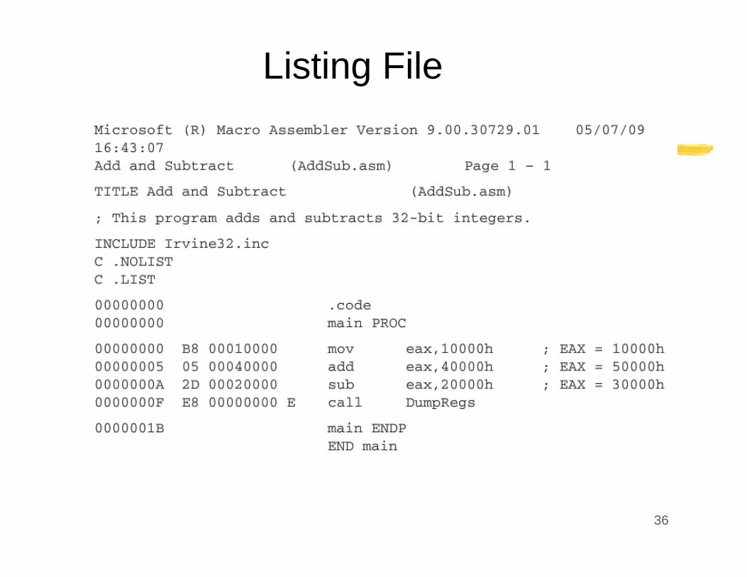
Listing File
36

Listing File
37

Listing File
38

Web Page for Instruction and Link Library
39