DPP Source Development Status - Blue Sky eLearnclient.blueskybroadcast.com/SPIE/EUV08/content/pdf/02...
22
DPP Source Development Status panel discussion: “Reliable High Power EUV Source Technology for HVM: LPP or DPP ? ” EUVL Workshop, June 10-12, 2008, Maui J.Kleinschmidt
Transcript of DPP Source Development Status - Blue Sky eLearnclient.blueskybroadcast.com/SPIE/EUV08/content/pdf/02...

DPP Source Development Status
panel discussion:
“Reliable High Power EUV Source Technology for HVM: LPP or DPP ? ”
EUVL Workshop, June 10-12, 2008, Maui
J.Kleinschmidt

2008 International Workshop on EUV Lithography, June 10-12, 2008, Maui, HI 2
LPP DPP
Starting point

2008 International Workshop on EUV Lithography, June 10-12, 2008, Maui, HI 3
LPP DPP
We will come back to these argumentswith updated values after the presentation of our DPP development status

2008 International Workshop on EUV Lithography, June 10-12, 2008, Maui, HI 4
We started with 2 approaches• high electrical input pulse energies (> 6J ) at
moderate repetition rates (10 kHz - 20 kHz) based on RDE source Laser Assisted Tin Droplet evaporation (LAD)
• high repetition rates ( > 40 kHz ) at electrical input pulse energies ≤
6J based on RDE source
with Laser Assisted Tin Surface evaporation (LAS)
Status DPP development

2008 International Workshop on EUV Lithography, June 10-12, 2008, Maui, HI 5
Status DPP development laser assisted
Tin droplet evaporation Tin surface evaporation
Tin droplets / diameter : 85 μm , frequency:105 kHz direction of the droplet stream : horizontal
Distance to nozzle: 60 mm
Distance to nozzle: 270 mm
•••
•
dropletbeam
LAD arrangement :droplet on demand andcontinuous droplet injection have been tested

2008 International Workshop on EUV Lithography, June 10-12, 2008, Maui, HI 6
Tin surface evaporationtotal emission
∅
1.3 mm
Status DPP development
0
50
100
150
200
250
0 5 10 15 20
input pulse energy / J
EUV
pul
se e
nerg
y / m
J/2
π
Tin droplet evaporationtotal emission∅
1.3 mm
♦♦♦
laser assistedTin droplet evaporation Tin surface evaporation
main results /Tin droplet evaporation :
EUV pulse energy ~ 100 mJ /2π
out of ∅
1 … 1.3 mmoperating modes
- single shot - burst regime
100 pulses , 5 kHz500 W / 2π

2008 International Workshop on EUV Lithography, June 10-12, 2008, Maui, HI 7
Summary
•
Demonstrated intrinsic conversion efficiency ~ 2% for both cases
•
No benefits of LAD concerning the collectable ( ∅
1.3 mm ) EUV pulse energies ( mJ/2π ) for input pulse energy range < 10 J
•
Mass limited Tin injection with LAD is possible but needs droplet diameters < 40 μm for a source with ~ 1000 W/2π inband power and ~ 10 kHz repetition rate, very difficult to realize
•
The LAD arrangement is more complex comparatively because of the Tin droplet generation and injection
Status DPP development laser assisted
Tin droplet evaporation Tin surface evaporation

2008 International Workshop on EUV Lithography, June 10-12, 2008, Maui, HI 8
Conclusion:Because of the relatively higher complexity, and possibly worse reliability of LAD , we favored LAS
Question:Is the RDE technology with laser assisted Tin surface ( LAS ) evaporation scalable to HVM power level ?
Status DPP development laser assisted
Tin droplet evaporation Tin surface evaporation

2008 International Workshop on EUV Lithography, June 10-12, 2008, Maui, HI 9
Power scaling of RDE-DPP with LAS
• Higher EUV powers up to HVM ranges can be achieved by
– Increased electrical pulse energy (E)– Increased pulse frequency (f)– Improved conversion efficiency (CE)
• Design of proof-of-principleexperiments using the same basic principle and slightly modified alpha source hardware
Tin bath
capacitor bank
laserVacuum
Tin Film
coolingE
CE
f
1.3 mm ∅
Status DPP development

10
Constant CE and collection efficiency
Coll.eff.=70%
34 mJ
1 mm1 mm
82 mJ
Coll.eff.=68%
0 2 4 6 80
1
2
3
4
0
20
40
60
80
100
intri
nsic
CE
[%]
input energy [J]
colle
ctio
n ef
ficie
ncy
[%]
0 2 4 6 80
20
40
60
80
100
outp
ut e
nerg
y [m
J/2π
]
input energy [J]
Power scaling: pulse energy
Status DPP development
2008 Workshop on EUV Lithography, June 10-12, 2008, Maui,HI

11
Averaged over 128 measurements
Δt=10 μs (f=100 kHz)
Δt=200 μs (f = 5 kHz)
Coll. eff. = 67%1 mmColl. eff. = 67%
f = 1/Δt time
ΔT fixed Δt variable
Double pulse experiment to mimic high frequency f
Coll. eff. = 65%
0 20 40 60 80 100 1200
1000
2000
3000
4000
outp
ut p
ower
[W/2
π]
frequency [kHz]
0 20 40 60 80 100 1200
20
40
60
80
100
outp
ut e
nerg
y [m
J/2π
]
frequency [kHz]
Power record:3800 W / 2π
Power scaling: frequency Constant CE and collection efficiency
Status DPP development
2008 Workshop on EUV Lithography, June 10-12, 2008, Maui,HI

2008 International Workshop on EUV Lithography, June 10-12, 2008, Maui, HI 12
Latest result using liquid tin electrodes 300 pulses at 40 kHz
No accumulation of plasma remnants
Double pulses good mimic for high frequency operation
0 50 100 150 200 250 3000
10
20
300 2 4 6
EU
V [m
J/2π
]
pulse number
time [ms]
Status DPP development

13
Status of heat removal capability
• Tin Handling Box (for electrode cooling) for 100kW input power– Improved cooling needed → active tin pumping
– Component release for high reliability
• Debris Mitigation System for 100kW input power– Building on 4 years of Sn DMT experience
– Water cooled → temperatures remain under control
PumpWater Chiller
Heat Transfer
Circulation
Lamp Head
Bath
520 K
700 K
600 K
650 K
550 K
max. 590°C cooling water
Releasing integrated source and SoCoMo at Beta power levels starts 2008
2008 Workshop on EUV Lithography, June 10-12, 2008, Maui,HI
Status DPP development

2008 International Workshop on EUV Lithography, June 10-12, 2008, Maui, HI 14
Philips/Xtreme IF power roadmap supporting timely introduction of Beta and HVM
Q4/07 Q4/08 Q4/09 Q4/10 Q4/11 Q4/12 Q4/13
10
100
10
100
EU
V in
band
pow
er a
t IF
(W)
Time
Alpha based
Beta product
500500
HVM product
Status DPP development

2008 International Workshop on EUV Lithography, June 10-12, 2008, Maui, HI 15
• Last year’s results:
• New debris mitigation system shows 10Gshot lifetime proven by accelerated lifetime tests on samples
• More resistent collector materials realize additional 6x lifetime increase
0
0,5
1
1,5
2
2,5
3
3,5
4
4,5
5
0 20 40 60 80 100 120Operating hours
EUV
pow
er @
IF (a
lpha
col
lect
or)
/ W
Constant EUV power at intermediate focus !
continuous operation
1 Gshot
=> 60Gshot or half-year lifetime already
+ =
0 5 10 15 20 25 300
20
40
60
80
100
exposed sample reference sample
Ref
lect
ivity
/ %
angle / °
Status DPP development
Collector lifetime

2008 International Workshop on EUV Lithography, June 10-12, 2008, Maui, HI 16
Summary
•
Demonstrated intrinsic conversion efficiencies in the range of ~ 2 % up to 6 J input pulse energy
•
cooling capability of important components sufficientfor ~ 100 kW electrical input power ( current status )
•
DPP sources with laser assisted Tin surface evaporation are scalable to HVM power level,
•
4 sr grazing incidence collector feasible
•
proven lifetime of optical samples > 10 Gshot10 Gshot (DPP) corresponds to ~ 200 Gshot (LPP)
Status DPP development
2008 International Workshop on EUV Lithography, June 10-12, 2008, Maui, HI 17
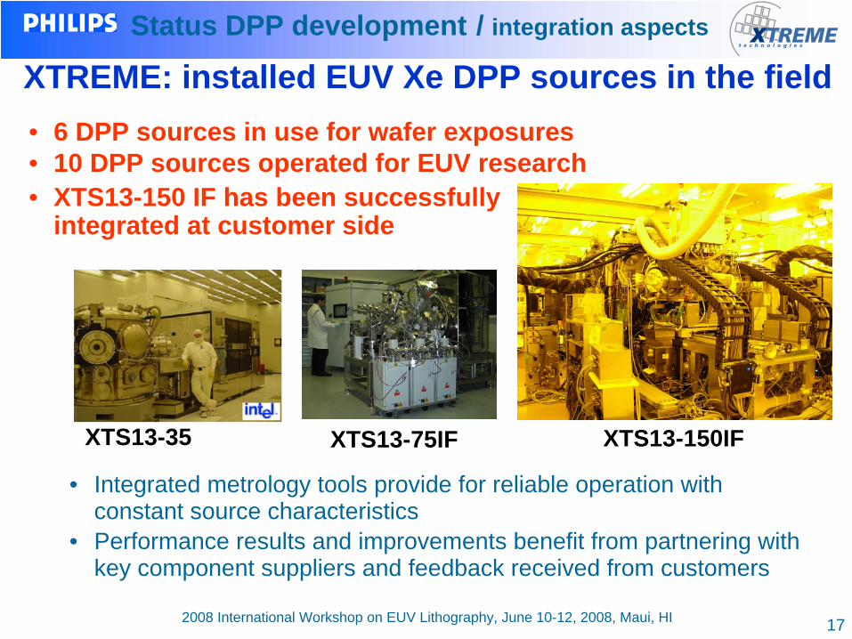
• Integrated metrology tools provide for reliable operation with constant source characteristics
• Performance results and improvements benefit from partnering with key component suppliers and feedback received from customers
Status DPP development / integration aspects
XTREME: installed EUV Xe DPP sources in the field• 6 DPP sources in use for wafer exposures• 10 DPP sources operated for EUV research• XTS13-150 IF has been successfully
integrated at customer side
XTS13-75IFXTS13-35 XTS13-150IF

2008 International Workshop on EUV Lithography, June 10-12, 2008, Maui, HI 18
Philips: installed EUV Sn DPP sources in the field
• All sources and SoCoMos running 100% duty cycle• On-site service engineers presence leads to short feedback loops
and continuous improvements on all spec points
• ASML – Veldhoven / Netherlands• IMEC – Leuven / Belgium• CNSE – Albany / USA• 5 operational sources in development
in Aachen / Germany
Albany/Leuve n
Aachen
Status DPP development / integration aspects

2008 International Workshop on EUV Lithography, June 10-12, 2008, Maui, HI 19
LPP DPP
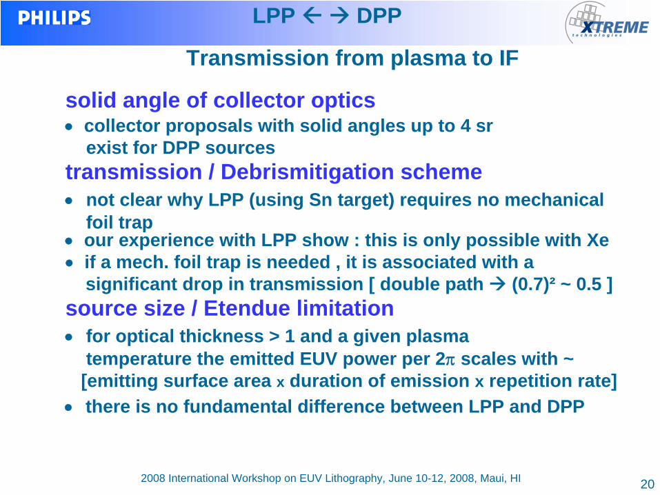
Transmission from plasma to IF
see:remarks onnext page
updated table DPP LPPclaimed
LPPrealistic
coll solid angle / 2π X reflectivity(50%)
0.32 ( 4 sr ) 0.36 ( 5 sr ) 0.36 ( 5 sr )
transmission of Debris tool 0.7 1 ~ 0.5
aperture transmission(Etendue limitation)
0.5 1 ~ 0.7
gas transmission 0.9 0.9 0.9
total transmission 0.1 0.32 ~ 0.11
LPP coll. eff. / DPP coll.eff.
~ 3 ~ 1
2008 International Workshop on EUV Lithography, June 10-12, 2008, Maui, HI 20
solid angle of collector optics•
collector proposals with solid angles up to 4 sr exist for DPP sources
transmission / Debrismitigation scheme•
not clear why LPP (using Sn target) requires no mechanical foil trap
•
our experience with LPP show : this is only possible with Xe•
if a mech. foil trap is needed , it is associated with a significant drop in transmission [ double path (0.7)² ~ 0.5 ]
source size / Etendue limitation•
for optical thickness > 1 and a given plasma temperature the emitted EUV power per 2π
scales with ~ [emitting surface area x duration of emission x repetition rate]
•
there is no fundamental difference between LPP and DPP
LPP DPP
Transmission from plasma to IF

2008 International Workshop on EUV Lithography, June 10-12, 2008, Maui, HI 21
Summary / physical background• Tin plasma densities for CO2 - LPP ( ncrit = 1019 cm-3)
nearly same as for DPP ( 1 … 5 1018 cm-3 )• about same plasma temperature of ~ 35… 40 eV⇒
for optical thickness > 1 and a given plasma temperature the emitted EUV power in 2π
scales with ~ [emitting surface area x duration of emission x repetition rate]
⇒ same EUV power in 2π at same repetition rate will result in same plasma size
• Demonstrated conversion efficiencies for both technologies in the range 2 – 3 %No principal advantage based on physical background for LPP generation of EUV light
LPP DPP
2008 International Workshop on EUV Lithography, June 10-12, 2008, Maui, HI 22
Summary / integration aspects
• DPP sources at the time technically superior ( integrated sources in field , long term operation )
• LPP sources still at the stage of laboratory sources ( no integrated system in the field, short term operation )
• LPP is missing experience in the system engineering and has no long-term advantages over DPP
LPP DPP