DP Sensors Input Mangement
24
DP Operator Course DP Sensors Input Management Training Manual July 2010 Kongsberg Maritime AS Page 4.5.1 Rev. 11 Training DP Sensors Input Mangement Introduction The Kongsberg Dynamic Positioning (K-Pos DP) systems need several different sensors to determine the position, heading and to calculate the necessary thrust output to position the vessel. In this chapter we will describe the different sensors and give some advice on how to handle the different sensors.
Transcript of DP Sensors Input Mangement

DP Operator Course DP Sensors Input Management
Training Manual
July 2010 Kongsberg Maritime AS Page 4.5.1
Rev. 11 Training
DP Sensors
Input Mangement
Introduction
The Kongsberg Dynamic Positioning (K-Pos DP) systems need several different sensors to
determine the position, heading and to calculate the necessary thrust output to position the
vessel.
In this chapter we will describe the different sensors and give some advice on how to handle
the different sensors.
DP Sensors Input Management DP Operator Course
Training Manual
Page 4.5.2 Kongsberg Maritime AS July 2010
Training Rev. 11
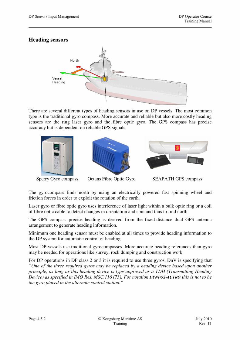
Heading sensors
There are several different types of heading sensors in use on DP vessels. The most common
type is the traditional gyro compass. More accurate and reliable but also more costly heading
sensors are the ring laser gyro and the fibre optic gyro. The GPS compass has precise
accuracy but is dependent on reliable GPS signals.
Sperry Gyro compass Octans Fibre Optic Gyro SEAPATH GPS compass
The gyrocompass finds north by using an electrically powered fast spinning wheel and
friction forces in order to exploit the rotation of the earth.
Laser gyro or fibre optic gyro uses interference of laser light within a bulk optic ring or a coil
of fibre optic cable to detect changes in orientation and spin and thus to find north.
The GPS compass precise heading is derived from the fixed-distance dual GPS antenna
arrangement to generate heading information.
Minimum one heading sensor must be enabled at all times to provide heading information to
the DP system for automatic control of heading.
Most DP vessels use traditional gyrocompasses. More accurate heading references than gyro
may be needed for operations like survey, rock dumping and construction work.
For DP operations in DP class 2 or 3 it is required to use three gyros. DnV is specifying that
“One of the three required gyros may be replaced by a heading device based upon another
principle, as long as this heading device is type approved as a TDH (Transmitting Heading
Device) as specified in IMO Res. MSC.116 (73). For notation DYNPOS-AUTRO this is not to be
the gyro placed in the alternate control station.”
DP Operator Course DP Sensors Input Management
Training Manual
July 2010 Kongsberg Maritime AS Page 4.5.3
Rev. 11 Training
Gyro in position calculations
The heading input is first of all used by the DP system for automatic
heading control, but the heading is also used to find the vessels
position from the position measurements for each individual
position reference system.
Conversion from antenna position to vessel’s centre
The position-reference systems are measuring the position of an
antenna, transducer or gimbal’s head. The DP system needs to
convert those antenna positions to the vessel’s centre in order to
have one common point where all the position-reference systems
are compared. To do this we need to know the antennas’ position on
the vessel and the vessel’s heading.
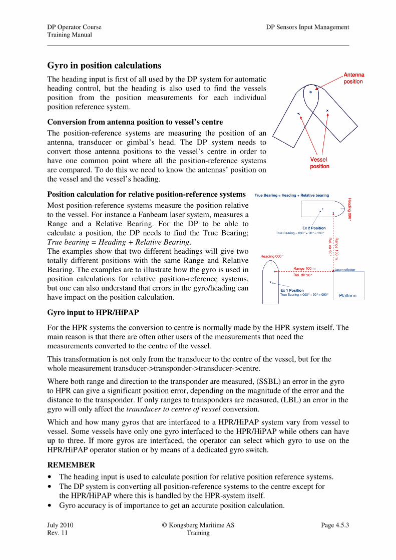
Position calculation for relative position-reference systems
Most position-reference systems measure the position relative
to the vessel. For instance a Fanbeam laser system, measures a
Range and a Relative Bearing. For the DP to be able to
calculate a position, the DP needs to find the True Bearing;
True bearing = Heading + Relative Bearing.
The examples show that two different headings will give two
totally different positions with the same Range and Relative
Bearing. The examples are to illustrate how the gyro is used in
position calculations for relative position-reference systems,
but one can also understand that errors in the gyro/heading can
have impact on the position calculation.
Gyro input to HPR/HiPAP
For the HPR systems the conversion to centre is normally made by the HPR system itself. The
main reason is that there are often other users of the measurements that need the
measurements converted to the centre of the vessel.
This transformation is not only from the transducer to the centre of the vessel, but for the
whole measurement transducer->transponder->transducer->centre.
Where both range and direction to the transponder are measured, (SSBL) an error in the gyro
to HPR can give a significant position error, depending on the magnitude of the error and the
distance to the transponder. If only ranges to transponders are measured, (LBL) an error in the
gyro will only affect the transducer to centre of vessel conversion.
Which and how many gyros that are interfaced to a HPR/HiPAP system vary from vessel to
vessel. Some vessels have only one gyro interfaced to the HPR/HiPAP while others can have
up to three. If more gyros are interfaced, the operator can select which gyro to use on the
HPR/HiPAP operator station or by means of a dedicated gyro switch.
REMEMBER
• The heading input is used to calculate position for relative position reference systems.
• The DP system is converting all position-reference systems to the centre except for
the HPR/HiPAP where this is handled by the HPR-system itself.
• Gyro accuracy is of importance to get an accurate position calculation.
Antenna
position
Vessel
position
Antenna
position
Vessel
position
Range 100 m
Rel. dir 90°
Ra
ng
e 1
00
m
Re
l. dir 9
0°
Platform
Laser reflector
Heading 000°
Hea
din
g 0
90
°
Ex 1 Position
Ex 2 Position
True Bearing = Heading + Relative bearing
True Bearing = 000° + 90° = 090°
True Bearing = 090° + 90° = 180°
DP Sensors Input Management DP Operator Course
Training Manual
Page 4.5.4 Kongsberg Maritime AS July 2010
Training Rev. 11
Latitude and speed corrections in gyros.
The gyro compass settles with its North-South axis at right angles to the resultant movement
of the Earth's rotation and the ship's movement. The error is westerly when sailing north and
easterly when sailing south. Sailing east or west gives no error. The magnitude of the error is
related to the vessels speed, course and latitude.
This error can be corrected for in most gyros. Traditionally one has set the latitude and speed
by means of knobs on the gyros panel. If the vessel had a speed log, this was normally
connected to the ships gyro, automatically compensating for the speed.
Today you will often find that a GPS is connected to the gyro in order to get an automatic
compensation for both speed and latitude. You need to be aware of that this connection
creates a new failure mode for DP where a position calculation error in the GPS will give a
wrong correction both for speed and latitude resulting in a sudden change in the gyro reading.
This error can easily become more than 10° because of high calculated speed in the GPS.
As described earlier, the vessel heading is also used to calculate measured positions from the
different position reference systems to the centre of the vessel, so a gyro error will also effect
the position of the vessel.
Exactly what will happen if the speed and latitude correction to gyros becomes wrong
depends on the vessel installations.
• If all gyros are corrected from different GPSes, a problem with satellites can still give
the same error in all of them. In this case you might get a heading out of limit message
and possibly a position out of limit which will be corrected by the DP by changing the
vessels heading and position. This again might effect the operation, and if close to
another object, possibly cause a collision.
• If the different GPSes is giving different speeds and latitudes, the gyros will be
corrected differently. A gyro might then be rejected, and if this leads to a change of
used gyro in the system, and there is a difference between the gyros, this again could
lead to a change in position and heading.
The only way to avoid this problem is to switch off the automatic speed and latitude
compensation in the gyros when on DP. Note that this problem will also affect the auto pilot
when sailing.
When operating on DP the vessel will be stationary or move slowly, and thus the speed error
in the gyros will be so small that they can be ignored and the automatic correction is not
needed.
RECOMMENDATION!
Kongsberg Maritime recommend that when on DP you should change the automatic
correction mode in the gyros to manual mode and set the correct latitude and the speed
to zero on the gyros own operator panel.

DP Operator Course DP Sensors Input Management
Training Manual
July 2010 Kongsberg Maritime AS Page 4.5.5
Rev. 11 Training
Operation/selection
The gyro dialogue is opened from the Sensor menu or by pushing the Gyro button on
the operator panel.
Sensor OK is a status signal coming
from the sensor itself and makes the
heading sensor available for selection.
Sensor Enable is a status set by the
operator to give the DP system access to
use the sensor.
The operator will normally enable all
available and reliable sensors.
There can be a maximum of three
sensors enabled at one time.
Sensor Preference is a status set by the
operator to tell the DP system which
sensor to use.
This sensor will be used as the DP
systems heading reference as long as the
sensor is reported OK and it is not rejected by any of the tests.
The operator should set Preference on the most reliable sensor.
In Use is a status signal coming from the DP controller indicating which sensor is used by the
system.
Gyro Heading is showing the heading received from each of the sensors.
Added Correction is a value the operator can set when a sensor is not enabled to correct the
sensors reading if it is not correct. Added correction can be used to compensate for an offset
of the ships gyrocompass compared with a surveyor’s gyrocompass. To ensure consistent data
for all users of a gyrocompass, it is recommended to adjust the gyrocompass itself.
Used Heading is the heading the DP system is using. This is the Gyro Heading + Added
Correction
Sensor view
The sensor view is showing each sensor reading, deviation between sensors and a historical
graph.
Gyro status lamp
The Gyro button on the operator panel has a status lamp that has three different statuses:
ON: at least one gyro enabled and accepted by the system
FLASHING: problems with either measurements (if more than one gyro selected), or
problems with the signals from the gyro.
OFF: no gyrocompasses are enabled.

DP Sensors Input Management DP Operator Course
Training Manual
Page 4.5.6 Kongsberg Maritime AS July 2010
Training Rev. 11
Tests, limits and messages
Message Description Message explain
Gyro difference
When 2 heading sensors are used and the
difference between them is more than 2° the
Gyro difference alarm will be given.
The DP operator needs to decide which of
the sensors are correct and then set
Preference on this sensor. The other sensor
should be disabled.
NOTE! If you switch to a sensor which has a
difference higher than the gyro prediction
error limit for the system you will get a Gyro
Prediction Error message and the sensor will
be rejected. (See the description of Gyro
Prediction Error). This implies that action has
to be taken immediately if the sensor that is
set as Preference starts to drift.
Description This message is reported if the difference between the
values read from two sensors exceeds a limit. The
reason for the message may be an error in one of the
sensors.
This message can only be given if two sensors are
enabled.
Additional information
Channel
Sensor number 1
Sensor number 2
Possible consequences
The system may use data from the sensor that has an
error.
Corrective actions
No action is necessary if the error message is only
reported occasionally. If reported frequently, check
which of the sensors that have the error, and if needed,
disable and repair the sensor.
Gyro rejected
When 3 sensors are used and one of them
deviates more than 2° from the median (the
one in the middle) it will be rejected.
If it is the sensor that is set as Preference
which is rejected, the DP system will switch
to the median sensor.
(The Preference will not switch, but the In
Use sensor will switch.)
The Gyro Rejected alarm will be given.
Description This message is reported if the difference between the
value that is read from the sensor and the median value
of all the enabled sensors of this type exceeds a limit.
The data from the sensor is not used by the DP system.
The reason for the message may be a faulty sensor.
This message can be reported when three or more
sensors of this type is enabled.
Additional information
Channel
Possible consequences
The DP system will automatically use data from the
other enabled sensors.
Corrective actions
No actions are necessary if the error message is only
reported occasionally. If reported frequently, disable
and repair the faulty sensor.
Gyro Prediction Error
If there is a difference of more than 6°
between the model and the measurement the
sensor is rejected by the prediction test. The
limit may be different for different vessels
and is set between 4° to 10°.
Note!
This message is given if two sensors are
enabled. If one sensor is enabled the system
will go directly to Heading Dropout and if
three sensors are enabled the failed sensor
will be rejected by the median test (voting).
Description
This message is reported if the difference between the
value read from the sensor and the Vessel Model value
exceeds a limit. This message is only given if two
sensors are enabled.
The data from the erroneous sensor is not used by the
system.
The reason for the fault may be an error in the sensor.
Possible consequences
The DP system will automatically use data from the
other sensor (if enabled).
Corrective actions
Check the sensor - DP interface.
Consider to disable the sensor.
DP Operator Course DP Sensors Input Management
Training Manual
July 2010 Kongsberg Maritime AS Page 4.5.7
Rev. 11 Training
Description Message explain
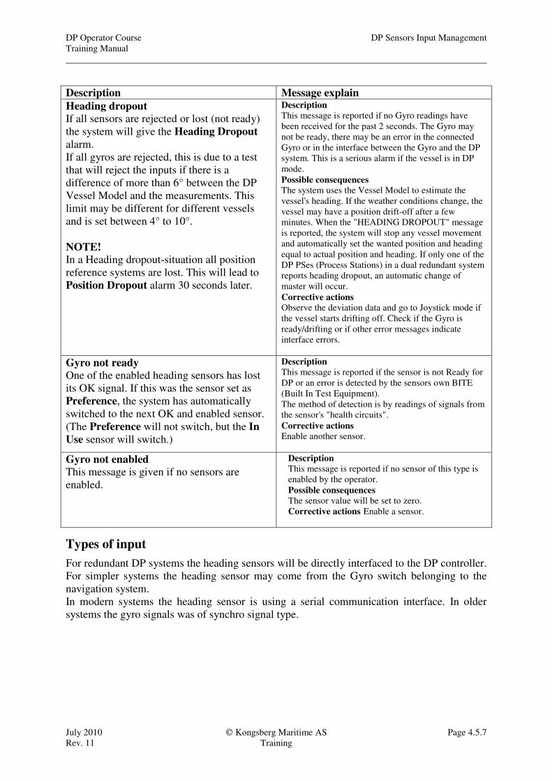
Heading dropout
If all sensors are rejected or lost (not ready)
the system will give the Heading Dropout
alarm.
If all gyros are rejected, this is due to a test
that will reject the inputs if there is a
difference of more than 6° between the DP
Vessel Model and the measurements. This
limit may be different for different vessels
and is set between 4° to 10°.
NOTE!
In a Heading dropout-situation all position
reference systems are lost. This will lead to
Position Dropout alarm 30 seconds later.
Description
This message is reported if no Gyro readings have
been received for the past 2 seconds. The Gyro may
not be ready, there may be an error in the connected
Gyro or in the interface between the Gyro and the DP
system. This is a serious alarm if the vessel is in DP
mode.
Possible consequences
The system uses the Vessel Model to estimate the
vessel's heading. If the weather conditions change, the
vessel may have a position drift-off after a few
minutes. When the "HEADING DROPOUT" message
is reported, the system will stop any vessel movement
and automatically set the wanted position and heading
equal to actual position and heading. If only one of the
DP PSes (Process Stations) in a dual redundant system
reports heading dropout, an automatic change of
master will occur.
Corrective actions Observe the deviation data and go to Joystick mode if
the vessel starts drifting off. Check if the Gyro is
ready/drifting or if other error messages indicate
interface errors.
Gyro not ready
One of the enabled heading sensors has lost
its OK signal. If this was the sensor set as
Preference, the system has automatically
switched to the next OK and enabled sensor.
(The Preference will not switch, but the In
Use sensor will switch.)
Description This message is reported if the sensor is not Ready for
DP or an error is detected by the sensors own BITE
(Built In Test Equipment).
The method of detection is by readings of signals from
the sensor's "health circuits".
Corrective actions Enable another sensor.
Gyro not enabled This message is given if no sensors are
enabled.
Description
This message is reported if no sensor of this type is
enabled by the operator.
Possible consequences
The sensor value will be set to zero.
Corrective actions Enable a sensor.
Types of input
For redundant DP systems the heading sensors will be directly interfaced to the DP controller.
For simpler systems the heading sensor may come from the Gyro switch belonging to the
navigation system.
In modern systems the heading sensor is using a serial communication interface. In older
systems the gyro signals was of synchro signal type.

DP Sensors Input Management DP Operator Course
Training Manual
Page 4.5.8 Kongsberg Maritime AS July 2010
Training Rev. 11
Notes on gyro alignment
Accurate alignment of the gyro axis to the ships axis is crucial to the accuracy of the DP.
A gyro alignment error will cause the following problems. 1. The vessels heading is wrong
2. The internal coordinate system in the DP is incorrect
3. The models position displayed on the DP screen is wrong.
4. The position reference systems will drift apart and the vessel will move when the vessel is changing
heading.
5. The position reference systems will drift apart when the vessel is moved.
The following example illustrates this.
Start situation:
Gyro alignment error 1° to
starboard.
All three PRS calibrated OK
• The GPS antenna is 10 meter ahead and 0.5 meter to port of the centre of the vessel.
• The Fanbeam unit is placed 11.6 meter ahead and 3.5 meter to port of the centre of the vessel and the
Fanbeam reflector is 50 meter to the port of the vessel.
• The HPR transponder B01 is 112 meter to the port of the vessel.
Situation 1:
The vessel has rotated 90° to
port from the initial heading.
Situation 2:
The vessel has moved 64
meter NW from the initial
position.
DP Operator Course DP Sensors Input Management
Training Manual
July 2010 Kongsberg Maritime AS Page 4.5.9
Rev. 11 Training
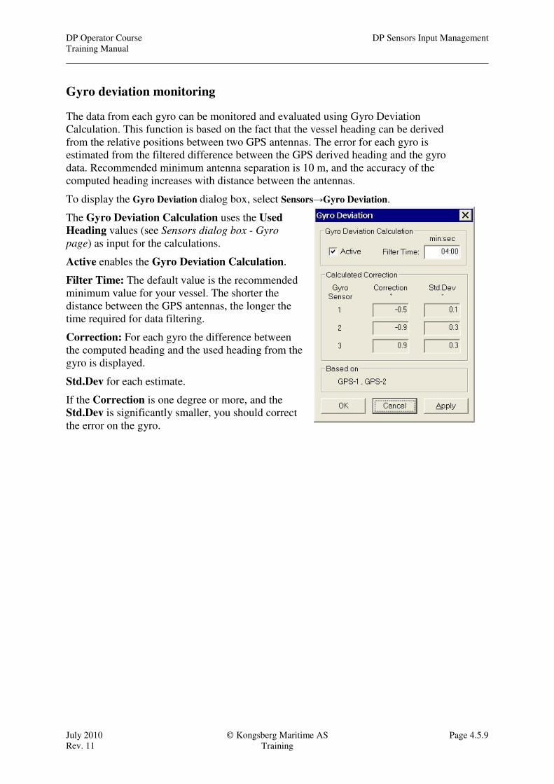
Gyro deviation monitoring
The data from each gyro can be monitored and evaluated using Gyro Deviation
Calculation. This function is based on the fact that the vessel heading can be derived
from the relative positions between two GPS antennas. The error for each gyro is
estimated from the filtered difference between the GPS derived heading and the gyro
data. Recommended minimum antenna separation is 10 m, and the accuracy of the
computed heading increases with distance between the antennas.
To display the Gyro Deviation dialog box, select Sensors→Gyro Deviation.
The Gyro Deviation Calculation uses the Used
Heading values (see Sensors dialog box - Gyro
page) as input for the calculations.
Active enables the Gyro Deviation Calculation.
Filter Time: The default value is the recommended
minimum value for your vessel. The shorter the
distance between the GPS antennas, the longer the
time required for data filtering.
Correction: For each gyro the difference between
the computed heading and the used heading from the
gyro is displayed.
Std.Dev for each estimate.
If the Correction is one degree or more, and the
Std.Dev is significantly smaller, you should correct
the error on the gyro.

DP Sensors Input Management DP Operator Course
Training Manual
Page 4.5.10 Kongsberg Maritime AS July 2010
Training Rev. 11
Vertical Reference Sensors
At least one vertical reference sensor must be available to provide the system with roll and
pitch information. This information is used to adjust the measurements received from the
position-reference systems for the vessel’s roll and pitch motions.
From the two examples above we see how the position measurements are effected by the
vessels motions. These effects are removed by referring the position reference systems to a
fixed horizontal plane generated by the Vertical Reference Sensor.
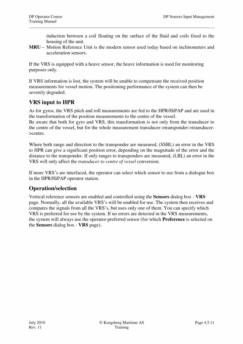
There are different types of sensors in use. The common term is VRS – Vertical Reference
Sensor. We are distinguishing between different types of sensors by giving then different
names.
VRU Datawell VRS MRU
VRU – Vertical Reference Unit. This term was used for a vertical gyro type used in the first
DP systems. The VRU is a unit used in the aviation industry to establish the artificial
horizon for the pilot.
VRS – Vertical Reference Sensor is the term we used for an analogue sensor made by
Datawell. A sphere half filled with a fluid is giving a horizontal plane. The motion of
the outer housing which is fixed to the vessels hull is measured by means of
DP Operator Course DP Sensors Input Management
Training Manual
July 2010 Kongsberg Maritime AS Page 4.5.11
Rev. 11 Training
induction between a coil floating on the surface of the fluid and coils fixed to the
housing of the unit.
MRU – Motion Reference Unit is the modern sensor used today based on inclinometers and
acceleration sensors.
If the VRS is equipped with a heave sensor, the heave information is used for monitoring
purposes only.
If VRS information is lost, the system will be unable to compensate the received position
measurements for vessel motion. The positioning performance of the system can then be
severely degraded.
VRS input to HPR
As for gyros, the VRS pitch and roll measurements are fed to the HPR/HiPAP and are used in
the transformation of the position measurements to the centre of the vessel.
Be aware that both for gyro and VRS, this transformation is not only from the transducer to
the centre of the vessel, but for the whole measurement transducer->transponder->transducer-
>centre.
Where both range and direction to the transponder are measured, (SSBL) an error in the VRS
to HPR can give a significant position error, depending on the magnitude of the error and the
distance to the transponder. If only ranges to transponders are measured, (LBL) an error in the
VRS will only affect the transducer to centre of vessel conversion.
If more VRS’s are interfaced, the operator can select which sensor to use from a dialogue box
in the HPR/HiPAP operator station.
Operation/selection
Vertical reference sensors are enabled and controlled using the Sensors dialog box - VRS
page. Normally, all the available VRS’s will be enabled for use. The system then receives and
compares the signals from all the VRS’s, but uses only one of them. You can specify which
VRS is preferred for use by the system. If no errors are detected in the VRS measurements,
the system will always use the operator-preferred sensor (for which Preference is selected on
the Sensors dialog box - VRS page).

DP Sensors Input Management DP Operator Course
Training Manual
Page 4.5.12 Kongsberg Maritime AS July 2010
Training Rev. 11
Sensor OK is a status signal coming
from the sensor itself and makes the
sensor available for selection.
Sensor Enable is a status set by the
operator to give the DP system access to
use the sensor.
The operator will normally enable all
available and reliable sensors.
There can be a maximum of three sensors
enabled at one time.
Sensor Preference is a status set by the
operator to tell the DP system which
sensor to use.
This sensor will be used as long as the
sensor is reported OK and it is not
rejected by any of the tests.
The operator should set Preference on the most reliable sensor.
In Use is a status signal coming from the DP controller indicating which sensor is used by the
system.
Pitch Roll and Heave is showing the pitch roll and heave received from each of the sensors.
Sensor view
The sensor view is showing each sensor reading for pitch, roll and heave, indicating which
sensor are used (white background) and the root mean square (RMS) values of the sensor
used.
VRS status lamp
The VRS button on the operator panel has a status lamp which shows the status of the VRS:
ON At least one VRS is enabled and accepted by the system.
FLASHING The measurements from one of the enabled VRSs are not accepted by the
system or an error situation exists in at least one of the VRS channels if only a
single VRS has been enabled.
OFF No VRS’s are enabled.
Types of input
The VRS sensors are directly interfaced to the DP controller.
The old VRUs were using synchro signals.
The Datawell VRS is using analogue signals ± 10 volt.
The MRUs can be interfaced either by serial communication or analogue ± 10 volt signals
DP Operator Course DP Sensors Input Management
Training Manual
July 2010 Kongsberg Maritime AS Page 4.5.13
Rev. 11 Training
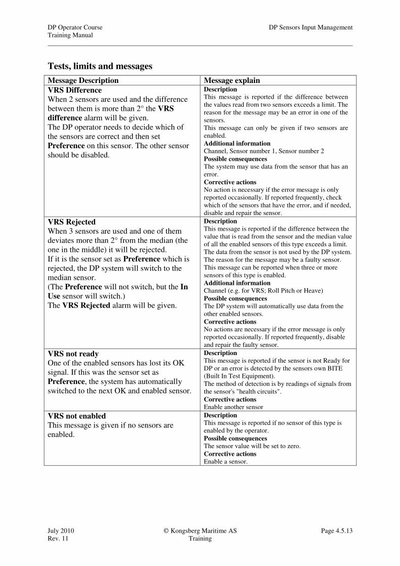
Tests, limits and messages
Message Description Message explain
VRS Difference
When 2 sensors are used and the difference
between them is more than 2° the VRS
difference alarm will be given.
The DP operator needs to decide which of
the sensors are correct and then set
Preference on this sensor. The other sensor
should be disabled.
Description This message is reported if the difference between
the values read from two sensors exceeds a limit. The
reason for the message may be an error in one of the
sensors.
This message can only be given if two sensors are
enabled.
Additional information
Channel, Sensor number 1, Sensor number 2
Possible consequences
The system may use data from the sensor that has an
error.
Corrective actions No action is necessary if the error message is only
reported occasionally. If reported frequently, check
which of the sensors that have the error, and if needed,
disable and repair the sensor.
VRS Rejected
When 3 sensors are used and one of them
deviates more than 2° from the median (the
one in the middle) it will be rejected.
If it is the sensor set as Preference which is
rejected, the DP system will switch to the
median sensor.
(The Preference will not switch, but the In
Use sensor will switch.)
The VRS Rejected alarm will be given.
Description This message is reported if the difference between the
value that is read from the sensor and the median value
of all the enabled sensors of this type exceeds a limit.
The data from the sensor is not used by the DP system.
The reason for the message may be a faulty sensor.
This message can be reported when three or more
sensors of this type is enabled.
Additional information Channel (e.g. for VRS; Roll Pitch or Heave)
Possible consequences The DP system will automatically use data from the
other enabled sensors.
Corrective actions No actions are necessary if the error message is only
reported occasionally. If reported frequently, disable
and repair the faulty sensor.
VRS not ready
One of the enabled sensors has lost its OK
signal. If this was the sensor set as
Preference, the system has automatically
switched to the next OK and enabled sensor.
Description
This message is reported if the sensor is not Ready for
DP or an error is detected by the sensors own BITE
(Built In Test Equipment).
The method of detection is by readings of signals from
the sensor's "health circuits".
Corrective actions Enable another sensor
VRS not enabled
This message is given if no sensors are
enabled.
Description
This message is reported if no sensor of this type is
enabled by the operator.
Possible consequences
The sensor value will be set to zero.
Corrective actions
Enable a sensor.

DP Sensors Input Management DP Operator Course
Training Manual
Page 4.5.14 Kongsberg Maritime AS July 2010
Training Rev. 11
Wind sensor
At least one wind sensor should normally be enabled to provide the system with wind speed
and direction information.
Normally, all available wind sensors will be enabled. The system then receives and compares
the signals from all the sensors, and if there are differences exceeding certain limits between
the sensors, a Wind difference message will be reported. Only one of the sensors is In Use to
calculate the wind force acting on the vessel. That is normally the sensor that the operator has
set as Preference.
Wind Feed-Forward
In order to counteract the wind forces as quickly as possible, the feed-forward concept is used.
This means that the DP system will not allow the vessel to drift away from the required
position, but automatically compensates for the wind forces acting on the vessel by providing
the thrusters with the necessary extra thrust in the appropriate direction as soon as the wind
forces are detected.
Operating without wind sensor input
There can be situations where you want to temporarily stop using the input from the wind
sensors, such as during helicopter operations or when operating close to another large
structure where there may be sudden disturbances of the measured wind. If you disable all the
wind sensors, the system continues to use the wind speed and direction values that were
measured just before the most recent wind sensor was disabled.
DP Operator Course DP Sensors Input Management
Training Manual
July 2010 Kongsberg Maritime AS Page 4.5.15
Rev. 11 Training
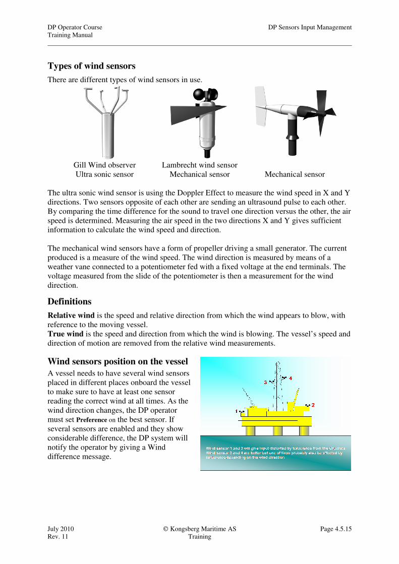
Types of wind sensors
There are different types of wind sensors in use.
Gill Wind observer Lambrecht wind sensor
Ultra sonic sensor Mechanical sensor Mechanical sensor
The ultra sonic wind sensor is using the Doppler Effect to measure the wind speed in X and Y
directions. Two sensors opposite of each other are sending an ultrasound pulse to each other.
By comparing the time difference for the sound to travel one direction versus the other, the air
speed is determined. Measuring the air speed in the two directions X and Y gives sufficient
information to calculate the wind speed and direction.
The mechanical wind sensors have a form of propeller driving a small generator. The current
produced is a measure of the wind speed. The wind direction is measured by means of a
weather vane connected to a potentiometer fed with a fixed voltage at the end terminals. The
voltage measured from the slide of the potentiometer is then a measurement for the wind
direction.
Definitions
Relative wind is the speed and relative direction from which the wind appears to blow, with
reference to the moving vessel.
True wind is the speed and direction from which the wind is blowing. The vessel’s speed and
direction of motion are removed from the relative wind measurements.
Wind sensors position on the vessel
A vessel needs to have several wind sensors
placed in different places onboard the vessel
to make sure to have at least one sensor
reading the correct wind at all times. As the
wind direction changes, the DP operator
must set Preference on the best sensor. If
several sensors are enabled and they show
considerable difference, the DP system will
notify the operator by giving a Wind
difference message.

DP Sensors Input Management DP Operator Course
Training Manual
Page 4.5.16 Kongsberg Maritime AS July 2010
Training Rev. 11
Wind sensor problems
Different situations might necessitate wind sensors to be de-selected. If all wind sensors are
de-selected, the DP system will continue to use the wind from the last period.
Wind sensor in turbulent area while the vessel is hit
by the wind coming under the platform. This gives
erroneous wind compensation from the DP system
and thus unstable positioning.
Wind sensors in the mast are measuring full wind
while the vessels hull is in sheltered area. This
gives over-compensation from the DP system and
as a result the positioning will be unstable.
A helicopter can disturb the wind measurements
resulting in unwanted reactions from the DP system
When sitting close to another installation you must
be aware of possible hazards like exhaust outlets or
water spray that may hit the wind sensors.
DP Operator Course DP Sensors Input Management
Training Manual
July 2010 Kongsberg Maritime AS Page 4.5.17
Rev. 11 Training
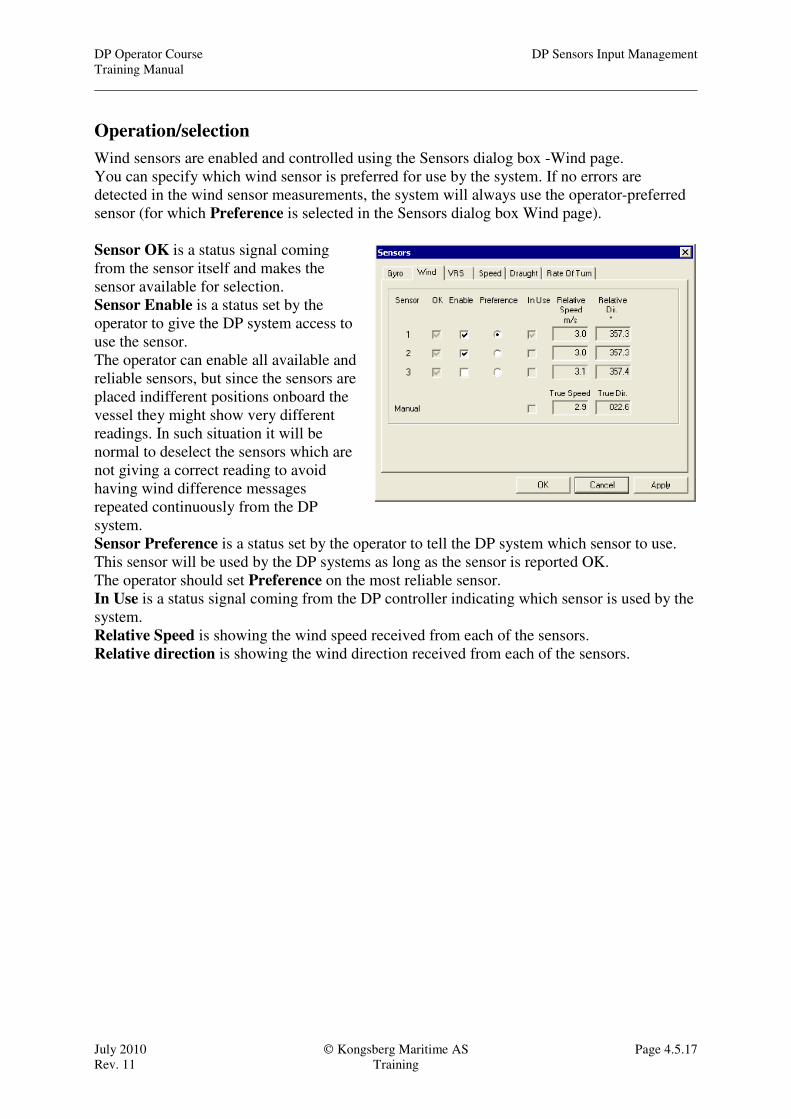
Operation/selection
Wind sensors are enabled and controlled using the Sensors dialog box -Wind page.
You can specify which wind sensor is preferred for use by the system. If no errors are
detected in the wind sensor measurements, the system will always use the operator-preferred
sensor (for which Preference is selected in the Sensors dialog box Wind page).
Sensor OK is a status signal coming
from the sensor itself and makes the
sensor available for selection.
Sensor Enable is a status set by the
operator to give the DP system access to
use the sensor.
The operator can enable all available and
reliable sensors, but since the sensors are
placed indifferent positions onboard the
vessel they might show very different
readings. In such situation it will be
normal to deselect the sensors which are
not giving a correct reading to avoid
having wind difference messages
repeated continuously from the DP
system.
Sensor Preference is a status set by the operator to tell the DP system which sensor to use.
This sensor will be used by the DP systems as long as the sensor is reported OK.
The operator should set Preference on the most reliable sensor.
In Use is a status signal coming from the DP controller indicating which sensor is used by the
system.
Relative Speed is showing the wind speed received from each of the sensors.
Relative direction is showing the wind direction received from each of the sensors.
DP Sensors Input Management DP Operator Course
Training Manual
Page 4.5.18 Kongsberg Maritime AS July 2010
Training Rev. 11
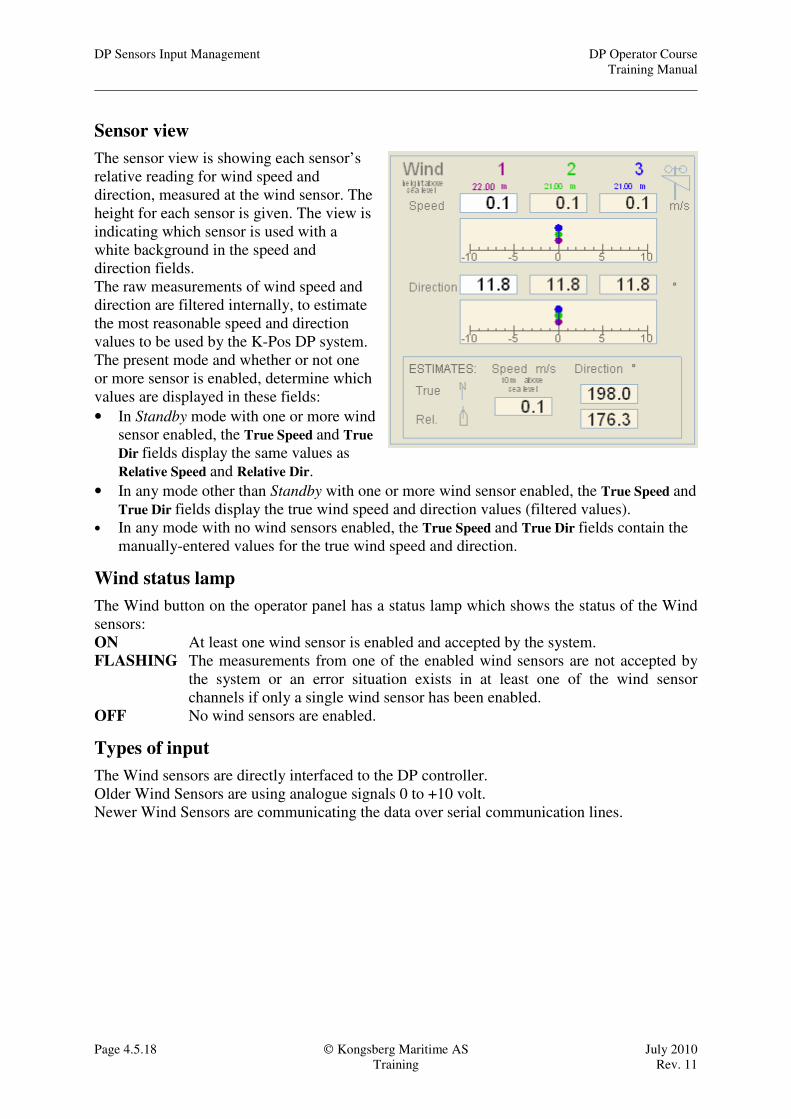
Sensor view
The sensor view is showing each sensor’s
relative reading for wind speed and
direction, measured at the wind sensor. The
height for each sensor is given. The view is
indicating which sensor is used with a
white background in the speed and
direction fields.
The raw measurements of wind speed and
direction are filtered internally, to estimate
the most reasonable speed and direction
values to be used by the K-Pos DP system.
The present mode and whether or not one
or more sensor is enabled, determine which
values are displayed in these fields:
• In Standby mode with one or more wind
sensor enabled, the True Speed and True
Dir fields display the same values as
Relative Speed and Relative Dir.
• In any mode other than Standby with one or more wind sensor enabled, the True Speed and
True Dir fields display the true wind speed and direction values (filtered values).
• In any mode with no wind sensors enabled, the True Speed and True Dir fields contain the
manually-entered values for the true wind speed and direction.
Wind status lamp
The Wind button on the operator panel has a status lamp which shows the status of the Wind
sensors:
ON At least one wind sensor is enabled and accepted by the system.
FLASHING The measurements from one of the enabled wind sensors are not accepted by
the system or an error situation exists in at least one of the wind sensor
channels if only a single wind sensor has been enabled.
OFF No wind sensors are enabled.
Types of input
The Wind sensors are directly interfaced to the DP controller.
Older Wind Sensors are using analogue signals 0 to +10 volt.
Newer Wind Sensors are communicating the data over serial communication lines.

DP Operator Course DP Sensors Input Management
Training Manual
July 2010 Kongsberg Maritime AS Page 4.5.19
Rev. 11 Training
Tests, limits and messages
Message Description Message explain
Wind difference
When more than one sensor is enabled and
the difference in speed is more than 6 m/s or
direction more than 45.8° the Wind
difference alarm will be given.
The DP operator needs to decide which of
the sensors are correct and then set
Preference on this sensor. The other sensor
should be disabled.
Description This message is reported if the difference between the
values read from two sensors exceeds a limit. The
reason for the message may be an error in one of the
sensors.
This message can only be given if two sensors are
enabled.
Additional information
Channel, Sensor number 1, Sensor number 2
Possible consequences
The system may use data from the sensor that has an
error.
Corrective actions No action is necessary if the error message is only
reported occasionally. If reported frequently, check
which of the sensors that have the error, and if
needed, disable and repair the sensor.
Wind sensor rejected
Faulty jumps in readings from a wind sensor
would lead to an unwanted increase in thrust
setpoint.
If the wind speed is above a predefined limit
a wind sensor will be rejected if the wind
measurement increases by more than a certain
limit over a certain interval or changes
direction of more than a certain limit over a
certain interval.
The alarm Wind sensor rejected is given:
The input data to the test is the difference
between new measurements, and low pass
filtered speed data with a small time constant.
A rejected sensor will be accepted again if it
is deselected and then selected again or if the
DP system is set to Standby mode
Description
The difference between the value received from the
sensor and previous values received exceeds fatal limit
and the sensor is rejected.
The reason for this fault may be an error in the sensor,
or its interface to the PS (Process Station).
Additional information
Failed measurement (Speed or Direction)
Measured value (m/s or degrees)
Filtered value (m/s or degrees)
Possible consequences
Wind data are frozen if only one wind sensor is
enabled. DP will loose dynamic update of wind data.
Corrective actions
Disable failed sensor.
Check failed sensor and its interface to the PS.
Wind Sensor not ready
One of the enabled sensors has lost its OK
signal. If this was the sensor set as
Preference, the system has automatically
switched to the next OK and enabled sensor.
(The Preference will not switch, but the In
Use sensor will switch.)
Description
This message is reported if the sensor is not Ready for
DP or an error is detected by the sensors own BITE
(Built In Test Equipment).
The method of detection is by readings of signals from
the sensor's "health circuits".
Corrective actions Enable another sensor.
Wind Sensor not enabled
This message is given if no sensors are
enabled.
Description
This message is reported if no sensor of this type is
enabled by the operator.
Possible consequences The sensor value will be set to zero.
Corrective actions
Enable a sensor.

DP Sensors Input Management DP Operator Course
Training Manual
Page 4.5.20 Kongsberg Maritime AS July 2010
Training Rev. 11
REMEMBER
Remember the following rules for automatic and manual switching of sensors!
With 3 Gyros
The DP system will use the gyro set as Preference as long as it is inside the median limit of
2°.
If the sensor set as Preference is voted out, the median gyro will be used.
The rejected gyro should be disabled.
With 2 Gyros
The DP system will normally always use the gyro set as Preference.
If the difference between the two gyros is more than 2° the Gyro difference alarm will be
given.
The DP operator has to decide which Gyro is correct and thus set Preference on that Gyro.
The faulty gyro should be disabled.
The DP Vessel Model will follow the gyro set as Preference. The DP operator should switch
to the correct gyro before the difference is more than 6° between the DP Vessel Model and
the correct gyro. If the difference is more than 6° when the switching is performed, the system
might go into Heading Dropout. (Limit is normally 6°, but can be configured from 4° to 10°)
If the Heading Dropout situation persists, to resolve the situation, the DP system must be set
to Standby mode before going back in with correct inputs.
Gyro OK
If the gyro set as Preference looses the OK signal the “next” gyro will be used.
The automatic switching will be from sensor 1 to sensor 2, from sensor 2 to sensor 3 and from
sensor 3 to sensor 1.
VRS
The same principles for switching apply as for Gyro.
Wind
DP system will always use sensor set as Preference if sensor is OK.
The operator should set Preference on the most correct sensor according to the prevailing
conditions and disable faulty sensors if necessary.
Switching as for Gyro, but there is no voting for wind sensors.

DP Operator Course DP Sensors Input Management
Training Manual
July 2010 Kongsberg Maritime AS Page 4.5.21
Rev. 11 Training
OTHER SENSORS
Draught sensor
For optimum positioning performance, the system must have accurate information regarding
the vessel’s draught at all times.
The vessel draught can either be specified by the operator or measured by a draught sensor.
The source of draught information is selected and controlled using the Sensors dialog box -
Draught page.
If the information from the draught sensors is correct and reliable, then this should be used in
preference to manually-entered or fixed values.
Sensor: When Sensor is selected, you
can enable the draught sensor that is to
be used. If more than one sensor is
enabled, the system uses the average of
all the enabled sensors. If Sensor is
selected but no sensors are enabled, the
Manual value is used by the system.
Manual: When manual is selected, the
draught value entered under Fixed
Draught is used by the system. If you
try to enter a value that is too high or
too low, the value is rejected by the
system and a message informing you
about the legal range for draught is
displayed.
Operation: When Operation is
selected, the predefined operational
draught value is used by the system.
Transit: When Transit is selected, the predefined transit draught value is used by the system.
Used Draught shows the draught value that is currently used by the system. This field is for
information only.
DP Sensors Input Management DP Operator Course
Training Manual
Page 4.5.22 Kongsberg Maritime AS July 2010
Training Rev. 11
Speed sensor
Speed measurements can be used as an addition to position measurements to improve the
vessel speed control in high speed modes (Auto Pilot, Auto Track High Speed and Seismic
Track). The speed information can be from different sources, e.g. Doppler Log sensors and
GPS speed sensors. You can enable available speed sensors or enter a manual alongships
vessel speed value. In high speed operations all enabled sensors will be used by the system
and an average is calculated. It is recommended to also enable Manual speed input since the
Manual value will be updated based on the In Use sensors. Should all sensors be lost, you then
have an initial Manual value that reflects the real situation.
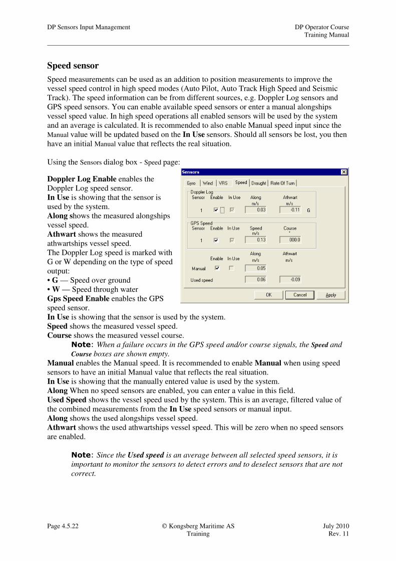
Using the Sensors dialog box - Speed page:
Doppler Log Enable enables the
Doppler Log speed sensor.
In Use is showing that the sensor is
used by the system.
Along shows the measured alongships
vessel speed.
Athwart shows the measured
athwartships vessel speed.
The Doppler Log speed is marked with
G or W depending on the type of speed
output:
• G — Speed over ground
• W — Speed through water
Gps Speed Enable enables the GPS
speed sensor.
In Use is showing that the sensor is used by the system.
Speed shows the measured vessel speed.
Course shows the measured vessel course.
Note: When a failure occurs in the GPS speed and/or course signals, the Speed and
Course boxes are shown empty.
Manual enables the Manual speed. It is recommended to enable Manual when using speed
sensors to have an initial Manual value that reflects the real situation.
In Use is showing that the manually entered value is used by the system.
Along When no speed sensors are enabled, you can enter a value in this field.
Used Speed shows the vessel speed used by the system. This is an average, filtered value of
the combined measurements from the In Use speed sensors or manual input.
Along shows the used alongships vessel speed.
Athwart shows the used athwartships vessel speed. This will be zero when no speed sensors
are enabled.
Note: Since the Used speed is an average between all selected speed sensors, it is
important to monitor the sensors to detect errors and to deselect sensors that are not
correct.
DP Operator Course DP Sensors Input Management
Training Manual
July 2010 Kongsberg Maritime AS Page 4.5.23
Rev. 11 Training
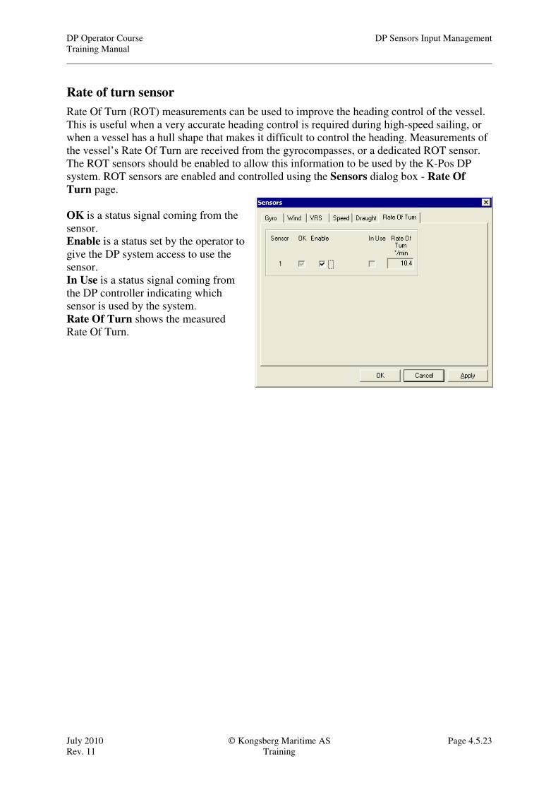
Rate of turn sensor
Rate Of Turn (ROT) measurements can be used to improve the heading control of the vessel.
This is useful when a very accurate heading control is required during high-speed sailing, or
when a vessel has a hull shape that makes it difficult to control the heading. Measurements of
the vessel’s Rate Of Turn are received from the gyrocompasses, or a dedicated ROT sensor.
The ROT sensors should be enabled to allow this information to be used by the K-Pos DP
system. ROT sensors are enabled and controlled using the Sensors dialog box - Rate Of
Turn page.
OK is a status signal coming from the
sensor.
Enable is a status set by the operator to
give the DP system access to use the
sensor.
In Use is a status signal coming from
the DP controller indicating which
sensor is used by the system.
Rate Of Turn shows the measured
Rate Of Turn.

DP Sensors Input Management DP Operator Course
Training Manual
Page 4.5.24 Kongsberg Maritime AS July 2010
Training Rev. 11
Tension sensors
Fore operations where forces are applied to the vessel these needs to be measured for the DP
system to work in a safe way. The forces measured will be added to the feed-forward and thus
directly compensated by the thrusters. Typical operations are ploughing, cable lay, pipe lay.
Force Surge: The force acting on the
vessel in the alongship direction.
Force Sway: The force acting on the
vessel in the athwartship direction.
Moment: The moment of the force
acting on the vessel.
None: The sensor is not used.
Measured: shows the measured
values from the tension sensors.
Manual: You can enter manual
tension values to be used in the
Manual text boxes
Calculated: The Moment is calculated
based on the selected Force Surge and
Force Sway.
Details: Click this button to show the
Details part of the dialog box.
Hide: Click this button to hide the
Details part of the dialog box.
Scale/Bias: Additional sensor scaling
can be entered. Used sensor value =
measured value*Scale/100 + Bias
Max value: Measurements will be
limited upwards to this value. To
avoid increasing tension until
something breaks, the maximum value
should be set to a safe level. This is
for example used for ploughing to
avoid breaking the towing wire if the
plough gets stuck on the seabed
Min value: Measurements will be
limited to this value. This function is
needed to hold a minimum tension in
the pipe, during pipe lay, to avoid the
vessel moving astern which would
result in a buckled or broken pipe.
Filter Constant: Because tension
measurements can be noisy it might be
necessary to filter them and to set a
time delay before the sensor is
reported erroneous.
Point of Attack: You can enter values
in the Along and Athwart text boxes to inform the system about the position of the point at
which the force is acting on the vessel.