DP Pump - Megacontrol
52
Control units Installation and operating instructions Series: Megacontrol
-
Upload
rahmat-nur-ilham -
Category
Documents
-
view
220 -
download
19
description
DP Pump - Megacontrol
Transcript of DP Pump - Megacontrol
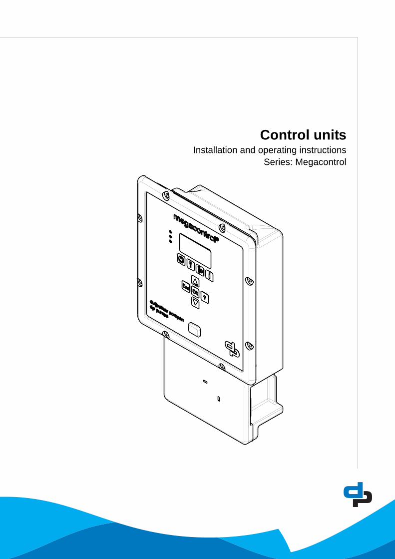
Control unitsInstallation and operating instructions
Series: Megacontrol

2
Table of Contents
1 Introduction1.1 Preface................................................................................................................................................... 41.2 Icons and symbols ................................................................................................................................. 4
2 Identification, service and technical support2.1 Identification, service and technical support .......................................................................................... 52.2 Supplementary documentation .............................................................................................................. 5
3 Warranty3.1 Terms of warranty .................................................................................................................................. 6
4 Safety and environment4.1 General .................................................................................................................................................. 74.2 Environmental aspects........................................................................................................................... 7
5 Introduction5.1 General .................................................................................................................................................. 85.2 Intended use .......................................................................................................................................... 85.3 Working range........................................................................................................................................ 85.4 Functioning ............................................................................................................................................ 9
6 Transport6.1 Transport and storage.......................................................................................................................... 10
7 Installation7.1 Mechanical installation..........................................................................................................................117.2 Electrical installation .............................................................................................................................117.3 Commissioning .................................................................................................................................... 12
8 Operation8.1 Control panel (HMI).............................................................................................................................. 138.2 Manual operation of the pumps ........................................................................................................... 158.3 Retrieve and reset a fault..................................................................................................................... 16
9 Hydro-unit configuration9.1 Hydro-Unit MC ..................................................................................................................................... 189.2 Hydro-Unit MC ++ ................................................................................................................................ 199.3 Hydro-Unit MCJ ................................................................................................................................... 209.4 Hydro-Unit MCF ................................................................................................................................... 219.5 Hydro-Unit MCMF ................................................................................................................................ 229.6 Hydro-Unit Level control ...................................................................................................................... 239.7 Explanation of parameters ................................................................................................................... 23
10 Parameters10.1 Parameter list....................................................................................................................................... 26
11 Faults11.1 Failure messages Megacontrol............................................................................................................ 4211.2 Failure messages Danfoss VFD .......................................................................................................... 43

3
12 Annexes12.1 Megacontrol ......................................................................................................................................... 4712.2 Built-in diagram.................................................................................................................................... 4812.3 Electrical connections .......................................................................................................................... 4812.4 EC Declaration of conformity ............................................................................................................... 51
4
1 Introduction
1.1 Preface
This manual contains important information for reliable, proper and efficient operation. Compliance with the operating instructions is of vital importance to ensure reliability and a long service life of the product and to avoid any risks.The first chapters contain information about this manual and safety in general. The following chapters provide information about normal use, installation, maintenance and repairs of the product. The annex contains the declaration(s) of conformity.
• Make yourself familiar with the content.• Accurately follow the directions and instructions.• Never change the sequence of the operations to
be carried out.• Keep this manual or a copy of it together with the
logbook in a fixed place near the product which can be accessed by all personnel.
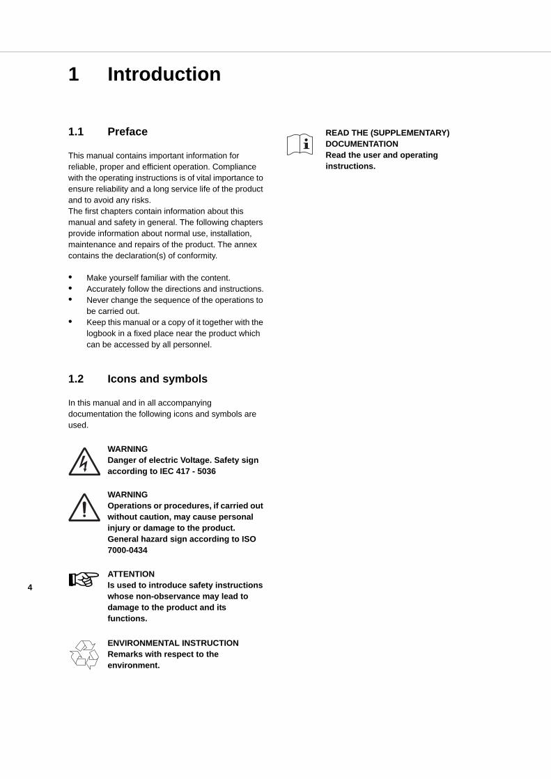
1.2 Icons and symbols
In this manual and in all accompanying documentation the following icons and symbols are used.
WARNINGDanger of electric Voltage. Safety sign according to IEC 417 - 5036
WARNINGOperations or procedures, if carried out without caution, may cause personal injury or damage to the product. General hazard sign according to ISO 7000-0434
ATTENTIONIs used to introduce safety instructions whose non-observance may lead to damage to the product and its functions.
ENVIRONMENTAL INSTRUCTIONRemarks with respect to the environment.
READ THE (SUPPLEMENTARY) DOCUMENTATIONRead the user and operating instructions.

5
2 Identification, service and technical support
2.1 Identification, service and technical support
The system is identified based on the text “Megacontrol” as given on the front of the system.Table 1: Control unit
The following address data are available for service and technical support:Table 2: Address service department
2.2 Supplementary documentation
This version is valid from Megacontrol version V1.57. Apart from this manual, the additional documentation given below is available as well:Table 3: Supplementary documentation
Table 4: Megacontrol versions
Indication MeaningMegacontrol Type of Control unit
DP-Pumps
Kalkovenweg 132401 LJ Alphen a/d RijnThe Netherlands
Tel: +31 172 488388Fax: +31 172 468930Internet: www.dp-pumps.comE-mail: [email protected]
Document Date/version CodeGeneral terms of delivery 10-1998 119 / 1998Manual WSD-Sensor 11-2009 BE00000250Technical documentationDocumentationAlso see: www.dp-pumps.com
Firm ware version (see parameter: 4-1-3) Manualversion
Megacontrol V 1.27 03-2008Megacontrol V 1.36 10-2009Megacontrol V 1.43 06-2011Megacontrol V 1.52 01-2013Megacontrol V 1.57 01-2014Also see: www.dp-pumps.com

6
3 Warranty
3.1 Terms of warranty
The warranty period is settled by the terms of your contract or at least by the general terms and conditions of sales.
ATTENTIONModifications or alterations of the product supplied are only permitted after consultation with the manufacturer. Original spare parts and accessories authorized by the manufacturer ensure safety. The use of other parts can invalidate any liability of the manufacturer for consequential damage.
ATTENTIONThe warranty relating to the operating reliability and safety of the product supplied is only valid if the product is used in accordance with its designated use as described in the following sections of this manual. The limits stated in the data sheet must not be exceeded under any circumstances.
The warranty becomes invalid if one or more of the points below occur.• The buyer makes modifications himself.• The buyer carries out repairs himself or has
these carried out by a third party.• The product has been handled or maintained
improperly.• The product has non original DP-Pumps spare
parts fitted.
DP-Pumps repairs defects under warranty when:
• They are caused by flaws in the design, the material or the production.
• They are reported within the warranty period.Other terms of warranty have been included in the general terms of delivery, which are available upon request.

7
4 Safety and environment
4.1 General
This DP-Pumps product has been developed using state-of-the-art technology; it is manufactured with utmost care and subject to continuous quality control.DP-Pumps does not accept any liability for damage and injury caused by not observing the directions and instructions in this manual, or in cases of carelessness during the installation procedure, use and maintenance of the product.Non-compliance with safety instructions can jeopardize the safety of personnel, the environment and the product itself. Non-compliance with these safety instructions will also lead to forfeiture of any and all rights to claims for damages. For example, in particular non-compliance can result in:
• failure of important pump/system functions,• failure of prescribed maintenance and servicing
practices,• injury to persons by electrical, mechanical and
chemical effects,• hazard of the environment due to leakage of
hazardous substances,• explosions.
Depending on specific activities, extra safety measures may be required. Contact DP-Pumps if a potential danger arises during use.
ATTENTIONThe owner of the product is responsible for compliance with the local safety regulations and internal company guidelines.
ATTENTIONNot only must the general safety instructions laid down in this chapter on "Safety" be complied with, but also the safety instructions outlined under specific headings.
4.2 Environmental aspects
4.2.1 GeneralThis product of DP-Pumps is designed to function in an environmentally friendly way during their entire life.
ENVIRONMENTAL INSTRUCTIONAlways act according to the laws, by-laws regulations and instructions with respect to health, safety and the environment.
4.2.2 DismantlingDismantle the product and dispose of it in an environmentally friendly way. The owner is responsible for this.
ENVIRONMENTAL INSTRUCTIONAsk at the local government about the re-use or the environmentally friendly processing of discarded materials.
ENVIRONMENTAL INSTRUCTIONAll components of the Megacontrol are manufactured in accordance with RoHS directive 2002/95/EC.
8
5 Introduction
5.1 General
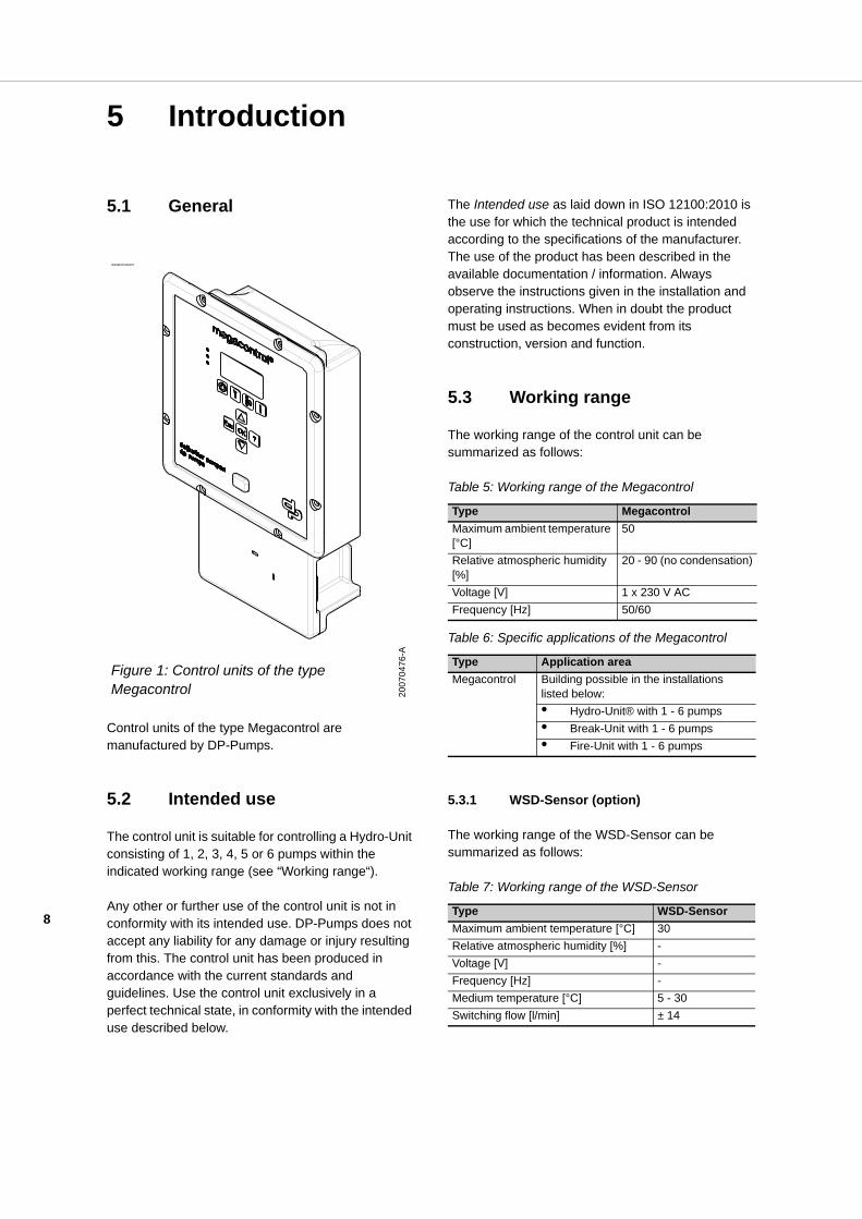
Control units of the type Megacontrol are manufactured by DP-Pumps.
5.2 Intended use
The control unit is suitable for controlling a Hydro-Unit consisting of 1, 2, 3, 4, 5 or 6 pumps within the indicated working range (see “Working range“).
Any other or further use of the control unit is not in conformity with its intended use. DP-Pumps does not accept any liability for any damage or injury resulting from this. The control unit has been produced in accordance with the current standards and guidelines. Use the control unit exclusively in a perfect technical state, in conformity with the intended use described below.
The Intended use as laid down in ISO 12100:2010 is the use for which the technical product is intended according to the specifications of the manufacturer. The use of the product has been described in the available documentation / information. Always observe the instructions given in the installation and operating instructions. When in doubt the product must be used as becomes evident from its construction, version and function.
5.3 Working range
The working range of the control unit can be summarized as follows:
Table 5: Working range of the Megacontrol
Table 6: Specific applications of the Megacontrol
5.3.1 WSD-Sensor (option)
The working range of the WSD-Sensor can be summarized as follows:
Table 7: Working range of the WSD-Sensor
ID2982/07062007
Figure 1: Control units of the type Megacontrol 20
0704
76-A
Type MegacontrolMaximum ambient temperature [°C]
50
Relative atmospheric humidity [%]
20 - 90 (no condensation)
Voltage [V] 1 x 230 V ACFrequency [Hz] 50/60
Type Application areaMegacontrol Building possible in the installations
listed below:• Hydro-Unit® with 1 - 6 pumps• Break-Unit with 1 - 6 pumps• Fire-Unit with 1 - 6 pumps
Type WSD-SensorMaximum ambient temperature [°C] 30Relative atmospheric humidity [%] -Voltage [V] -Frequency [Hz] -Medium temperature [°C] 5 - 30Switching flow [l/min] ± 14

9
Table 8: Specific applications WSD
5.4 Functioning
5.4.1 Standard operation
The Megacontrol is an intelligent control unit for different components of pressurization systems consisting out of a maximum of 6 pumps. The required system pressure is sensed by a pressure sensor on the outlet side of the installation.
When as a result of a decreasing water volume the pressure drops below the pressure set point, a pump will be switched on.
When the required system pressure has been reached, the pumps are switched off one at a time. The minimum run time is optimized constantly, which results in a considerable energy saving.
5.4.2 Custom made settings
The Megacontrol can be programmed through the human machine interface (HMI) operating panel and has been protected against unauthorized use by a password.
Also, the service port provides access to the parameters of the program which can be used to optimize the functionality of the installation, (see: “Parameter list”).
WARNINGFor access to the parameters of the program using the service port, always use the special service port cable!
The special service port cable (Art. nr. 6147117698) can by ordered separately.
5.4.3 Number of operating hours per pump
The current number of operating hours of a pump determines which pump will be switched on or off next. The pump with the fewest operating hours will be switched on first and the pump with the most operating hours will be switched off first. This makes sure that all pumps have an equal number of operating hours, including the backup pump.
5.4.4 Test run
In order to prevent pumps from standing still for a longer period of time, an automatic test run procedure is provided as a standard.
5.4.5 Functioning WSD-Sensor (option)
In combination with the Megacontrol, the WSD can generate a failure message when, during a (adjustable) period of time, insufficient refreshment of the membrane switch vessel occurs.
The failure message is generated when:• Insufficient refreshment occurs;• The membrane of the membrane switch vessel
is defective;• There is no air left in the membrane switch
vessel;• The installation is not set / installed correctly.
5.4.6 Temperature-sensor (option)
When the Megacontrol is fitted with a temperature sensor, it can generate a temperature-dependent failure message.
Type ApplicationsWSD Installations with a maximum of 3
membrane switch vessels.

10
6 Transport
6.1 Transport and storage
1. Transport the control unit in the position as indicated on the pallet or packaging.
2. Check if the control unit is stable.3. Observe the instructions on the packaging (if
present).
ATTENTIONStore the control unit in a dry and dust-free place.
11
7 Installation
7.1 Mechanical installation
ATTENTIONContact the supplier if parts are missing or damaged.
Build in the control unit using suitable fastening material. Consult the annex “Built-in diagram" for the correct overall dimensions.
7.2 Electrical installation
WARNINGOnly authorized personnel is allowed to connect the control unit electrically in accordance with the local regulations.
Electrical connections• Make sure that the electric control unit
specifications correspond with the power supply to which is connected.
• Consult the annex "Electrical diagram" for a list of all electrical power points.
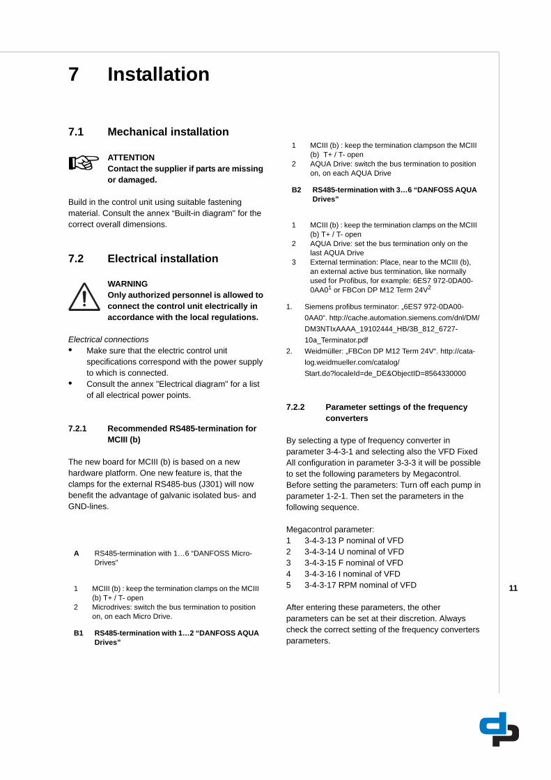
7.2.1 Recommended RS485-termination for MCIII (b)
The new board for MCIII (b) is based on a new hardware platform. One new feature is, that the clamps for the external RS485-bus (J301) will now benefit the advantage of galvanic isolated bus- and GND-lines.
7.2.2 Parameter settings of the frequency converters
By selecting a type of frequency converter in parameter 3-4-3-1 and selecting also the VFD Fixed All configuration in parameter 3-3-3 it will be possible to set the following parameters by Megacontrol.Before setting the parameters: Turn off each pump in parameter 1-2-1. Then set the parameters in the following sequence.
Megacontrol parameter:1 3-4-3-13 P nominal of VFD 2 3-4-3-14 U nominal of VFD 3 3-4-3-15 F nominal of VFD 4 3-4-3-16 I nominal of VFD 5 3-4-3-17 RPM nominal of VFD
After entering these parameters, the other parameters can be set at their discretion. Always check the correct setting of the frequency converters parameters.
A RS485-termination with 1…6 “DANFOSS Micro-Drives”
1 MCIII (b) : keep the termination clamps on the MCIII (b) T+ / T- open
2 Microdrives: switch the bus termination to position on, on each Micro Drive.
B1 RS485-termination with 1…2 “DANFOSS AQUA Drives”
1 MCIII (b) : keep the termination clampson the MCIII (b) T+ / T- open
2 AQUA Drive: switch the bus termination to position on, on each AQUA Drive
B2 RS485-termination with 3…6 “DANFOSS AQUA Drives”
1 MCIII (b) : keep the termination clamps on the MCIII (b) T+ / T- open
2 AQUA Drive: set the bus termination only on the last AQUA Drive
3 External termination: Place, near to the MCIII (b), an external active bus termination, like normally used for Profibus, for example: 6ES7 972-0DA00-0AA01 or FBCon DP M12 Term 24V2
1. Siemens profibus terminator: „6ES7 972-0DA00-0AA0“. http://cache.automation.siemens.com/dnl/DM/DM3NTIxAAAA_19102444_HB/3B_812_6727-10a_Terminator.pdf
2. Weidmüller: „FBCon DP M12 Term 24V“. http://cata-log.weidmueller.com/catalog/Start.do?localeId=de_DE&ObjectID=8564330000
12
7.2.3 Using contactors
ATTENTIONAlways place, using contactors and/or auxiliary relays, a suitable RC filter or varistor across the coil, e.g. Siemens 3RT29-16-1CD00
7.3 Commissioning
The control unit is fully programmed and preset with factory default settings. Use the control panel, or the service port to access the parameters of the program which can be used to optimize the functionality of the installation, (see: “Parameter list”).
13
8 Operation
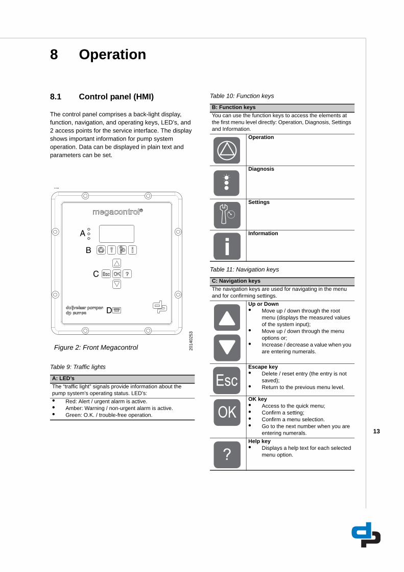
8.1 Control panel (HMI)
The control panel comprises a back-light display, function, navigation, and operating keys, LED’s, and 2 access points for the service interface. The display shows important information for pump system operation. Data can be displayed in plain text and parameters can be set.
Table 9: Traffic lights
Table 10: Function keys
Table 11: Navigation keys
ID 2944
Figure 2: Front Megacontrol 2014
0253
A: LED’sThe “traffic light” signals provide information about the pump system’s operating status. LED’s:• Red: Alert / urgent alarm is active.• Amber: Warning / non-urgent alarm is active.• Green: O.K. / trouble-free operation.
A
B
C
D
B: Function keysYou can use the function keys to access the elements at the first menu level directly: Operation, Diagnosis, Settings and Information.
Operation
Diagnosis
Settings
Information
C: Navigation keysThe navigation keys are used for navigating in the menu and for confirming settings.
Up or Down • Move up / down through the root
menu (displays the measured values of the system input);
• Move up / down through the menu options or;
• Increase / decrease a value when you are entering numerals.
Escape key • Delete / reset entry (the entry is not
saved);• Return to the previous menu level.
OK key • Access to the quick menu;• Confirm a setting;• Confirm a menu selection.• Go to the next number when you are
entering numerals.Help key• Displays a help text for each selected
menu option.
14
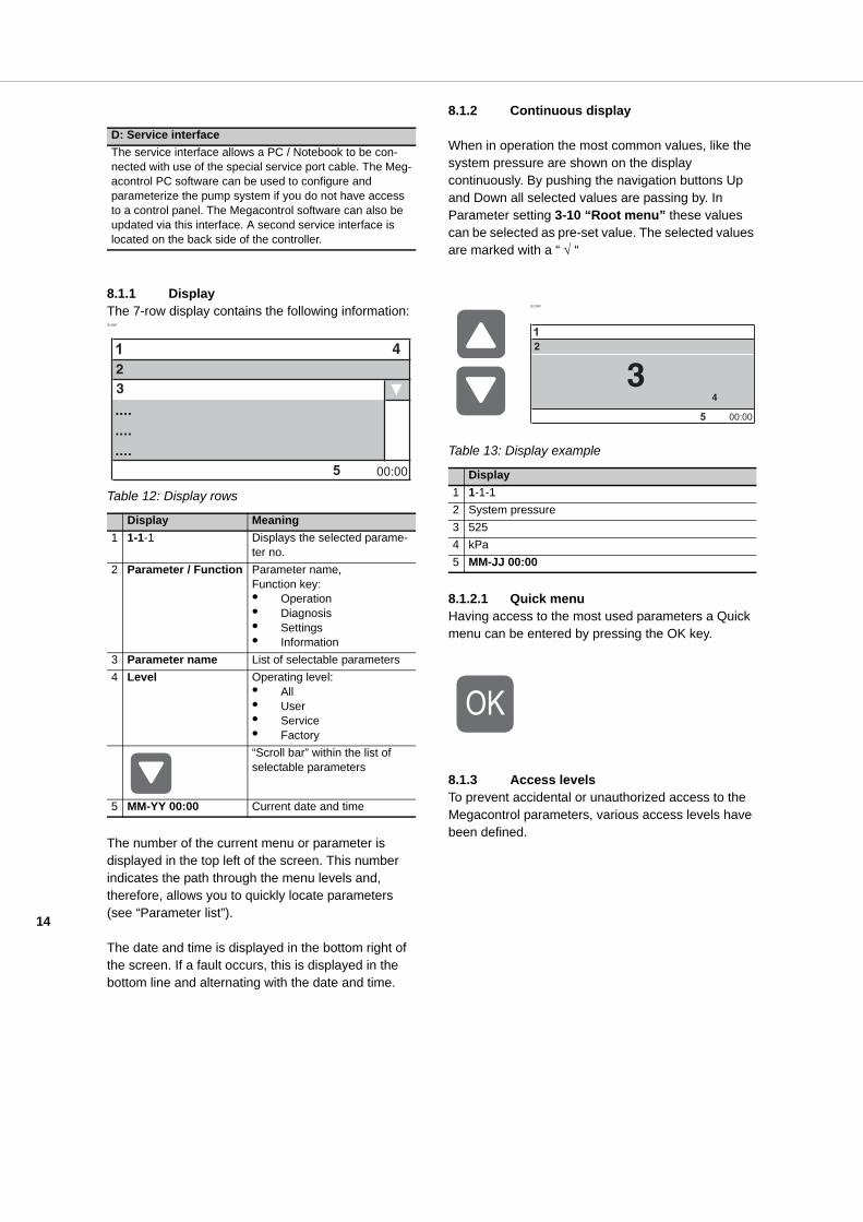
8.1.1 DisplayThe 7-row display contains the following information:ID 2987
Table 12: Display rows
The number of the current menu or parameter is displayed in the top left of the screen. This number indicates the path through the menu levels and, therefore, allows you to quickly locate parameters (see “Parameter list”).
The date and time is displayed in the bottom right of the screen. If a fault occurs, this is displayed in the bottom line and alternating with the date and time.
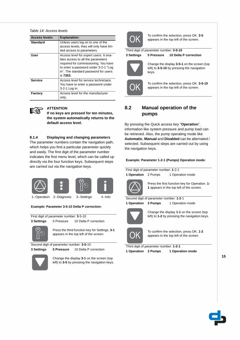
8.1.2 Continuous display
When in operation the most common values, like the system pressure are shown on the display continuously. By pushing the navigation buttons Up and Down all selected values are passing by. In Parameter setting 3-10 “Root menu” these values can be selected as pre-set value. The selected values are marked with a “ √ “
Table 13: Display example
8.1.2.1 Quick menuHaving access to the most used parameters a Quick menu can be entered by pressing the OK key.
8.1.3 Access levelsTo prevent accidental or unauthorized access to the Megacontrol parameters, various access levels have been defined.
D: Service interfaceThe service interface allows a PC / Notebook to be con-nected with use of the special service port cable. The Meg-acontrol PC software can be used to configure and parameterize the pump system if you do not have access to a control panel. The Megacontrol software can also be updated via this interface. A second service interface is located on the back side of the controller.
Display Meaning1 1-1-1 Displays the selected parame-
ter no.2 Parameter / Function Parameter name,
Function key: • Operation • Diagnosis• Settings • Information
3 Parameter name List of selectable parameters4 Level Operating level:
• All• User• Service • Factory“Scroll bar” within the list of selectable parameters
5 MM-YY 00:00 Current date and time
23
5
4
ID 2955
Display1 1-1-12 System pressure3 5254 kPa5 MM-JJ 00:00
2
35
4
15
Table 14: Access levels
ATTENTIONIf no keys are pressed for ten minutes, the system automatically returns to the default access level.
8.1.4 Displaying and changing parameters The parameter numbers contain the navigation path, which helps you find a particular parameter quickly and easily. The first digit of the parameter number indicates the first menu level, which can be called up directly via the four function keys. Subsequent steps are carried out via the navigation keys.
8.2 Manual operation of the pumps
By pressing the Quick access key “Operation”, information like system pressure and pump load can be retrieved. Also, the pump operating mode like Automatic, Manual and Disabled can be alternated / selected. Subsequent steps are carried out by using the navigation keys.
Access levels: Explanation:Standard Unless users log on to one of the
access levels, they will only have lim-ited access to parameters.
User Access level for expert users. It ena-bles access to all the parameters required for commissioning. You have to enter a password under 3-2-1 “Log in”. The standard password for users is 7353.
Service Access level for service technicians. You have to enter a password under 3-2-1 Log in.
Factory Access level for the manufacturer only.
1--Operation 2--Diagnosis 3--Settings 4--Info
Example: Parameter 3-5-10 Delta P correction:
First digit of parameter number: 3-5-103 Settings 5 Pressure 10 Delta P correction
Press the third function key for Settings. 3-1 appears in the top left of the screen.
Second digit of parameter number: 3-5-103 Settings 5 Pressure 10 Delta P correction
Change the display 3-1 on the screen (top left) to 3-5 by pressing the navigation keys.
To confirm the selection, press OK. 3-5 appears in the top left of the screen.
Third digit of parameter number: 3-5-103 Settings 5 Pressure 10 Delta P correction
Change the display 3-5-1 on the screen (top left) to 3-5-10 by pressing the navigation keys.
To confirm the selection, press OK. 3-5-10 appears in the top left of the screen.
Example: Parameter 1-2-1 (Pumps) Operation mode:
First digit of parameter number: 1-2-11 Operation 2 Pumps 1 Operation mode
Press the first function key for Operation. 1-1 appears in the top left of the screen.
Second digit of parameter number: 1-2-11 Operation 2 Pumps 1 Operation mode
Change the display 1-1 on the screen (top left) to 1-2 by pressing the navigation keys.
To confirm the selection, press OK. 1-2 appears in the top left of the screen.
Third digit of parameter number: 1-2-11 Operation 2 Pumps 1 Operation mode
16
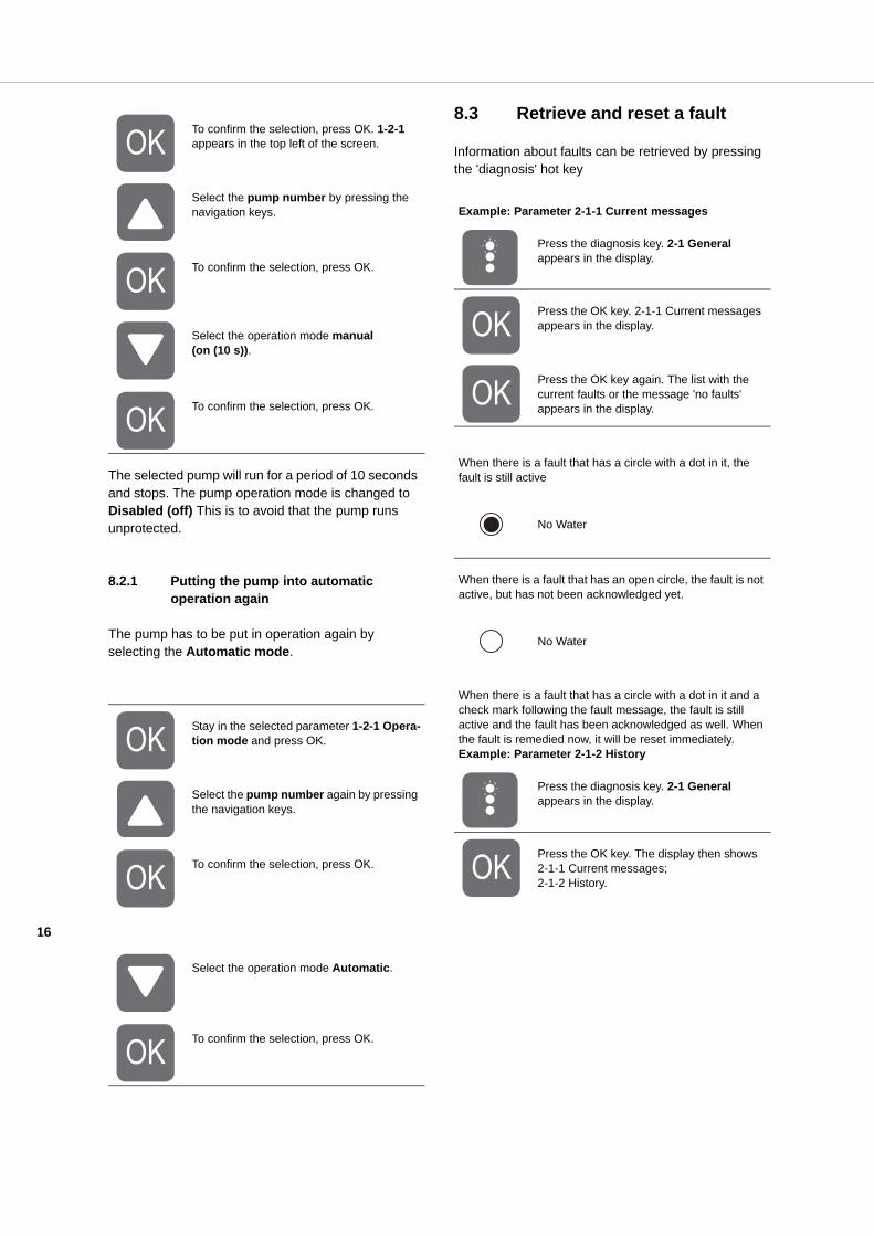
The selected pump will run for a period of 10 seconds and stops. The pump operation mode is changed to Disabled (off) This is to avoid that the pump runs unprotected.
8.2.1 Putting the pump into automatic operation again
The pump has to be put in operation again by selecting the Automatic mode.
8.3 Retrieve and reset a fault
Information about faults can be retrieved by pressing the 'diagnosis' hot key
To confirm the selection, press OK. 1-2-1 appears in the top left of the screen.
Select the pump number by pressing the navigation keys.
To confirm the selection, press OK.
Select the operation mode manual (on (10 s)).
To confirm the selection, press OK.
Stay in the selected parameter 1-2-1 Opera-tion mode and press OK.
Select the pump number again by pressing the navigation keys.
To confirm the selection, press OK.
Select the operation mode Automatic.
To confirm the selection, press OK.
Example: Parameter 2-1-1 Current messages
Press the diagnosis key. 2-1 General appears in the display.
Press the OK key. 2-1-1 Current messages appears in the display.
Press the OK key again. The list with the current faults or the message 'no faults' appears in the display.
When there is a fault that has a circle with a dot in it, the fault is still active
No Water
When there is a fault that has an open circle, the fault is not active, but has not been acknowledged yet.
No Water
When there is a fault that has a circle with a dot in it and a check mark following the fault message, the fault is still active and the fault has been acknowledged as well. When the fault is remedied now, it will be reset immediately.Example: Parameter 2-1-2 History
Press the diagnosis key. 2-1 General appears in the display.
Press the OK key. The display then shows 2-1-1 Current messages; 2-1-2 History.
17
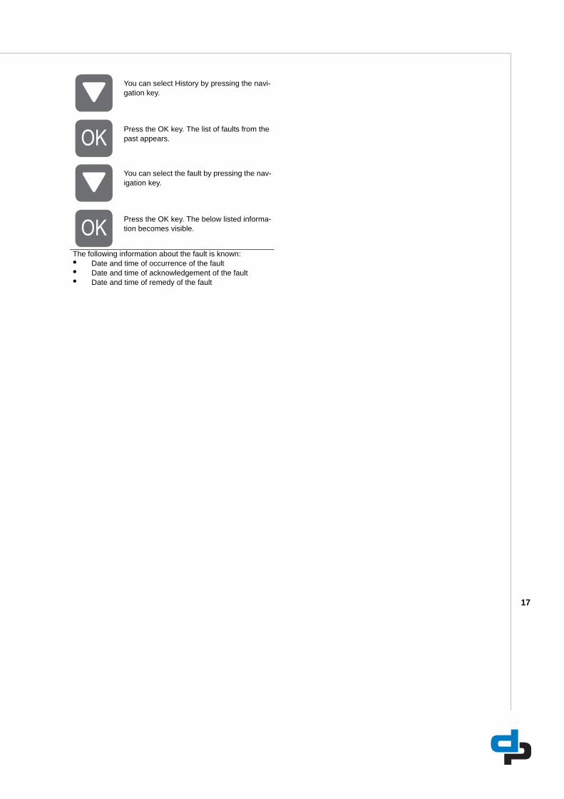
You can select History by pressing the navi-gation key.
Press the OK key. The list of faults from the past appears.
You can select the fault by pressing the nav-igation key.
Press the OK key. The below listed informa-tion becomes visible.
The following information about the fault is known:• Date and time of occurrence of the fault• Date and time of acknowledgement of the fault• Date and time of remedy of the fault
18
9 Hydro-unit configuration
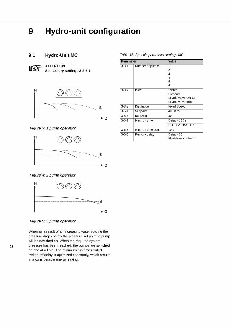
9.1 Hydro-Unit MC
ATTENTIONSee factory settings 3-2-2-1
When as a result of an increasing water volume the pressure drops below the pressure set point, a pump will be switched on. When the required system pressure has been reached, the pumps are switched off one at a time. The minimum run time related switch-off delay is optimized constantly, which results in a considerable energy saving.
Table 15: Specific parameter settings MC
Figure 3: 1 pump operation
Figure 4: 2 pump operation
Figure 5: 3 pump operation
Q
H
S
Q
H
S
Q
H
S
Parameter Value3-3-1 Number of pumps 1
23456
3-3-2 Inlet SwitchPressureLevel / valve ON-OFFLevel / valve prop.
3-3-3 Discharge Fixed Speed3-5-1 Set point 400 kPa3-5-3 Bandwidth 303-6-2 Min. run time Default 180 s
DOL ≤ 2.2 kW 90 s3-6-3 Min. run time corr. 10 s3-6-8 Run-dry delay Default 30
Float/level control 1
19
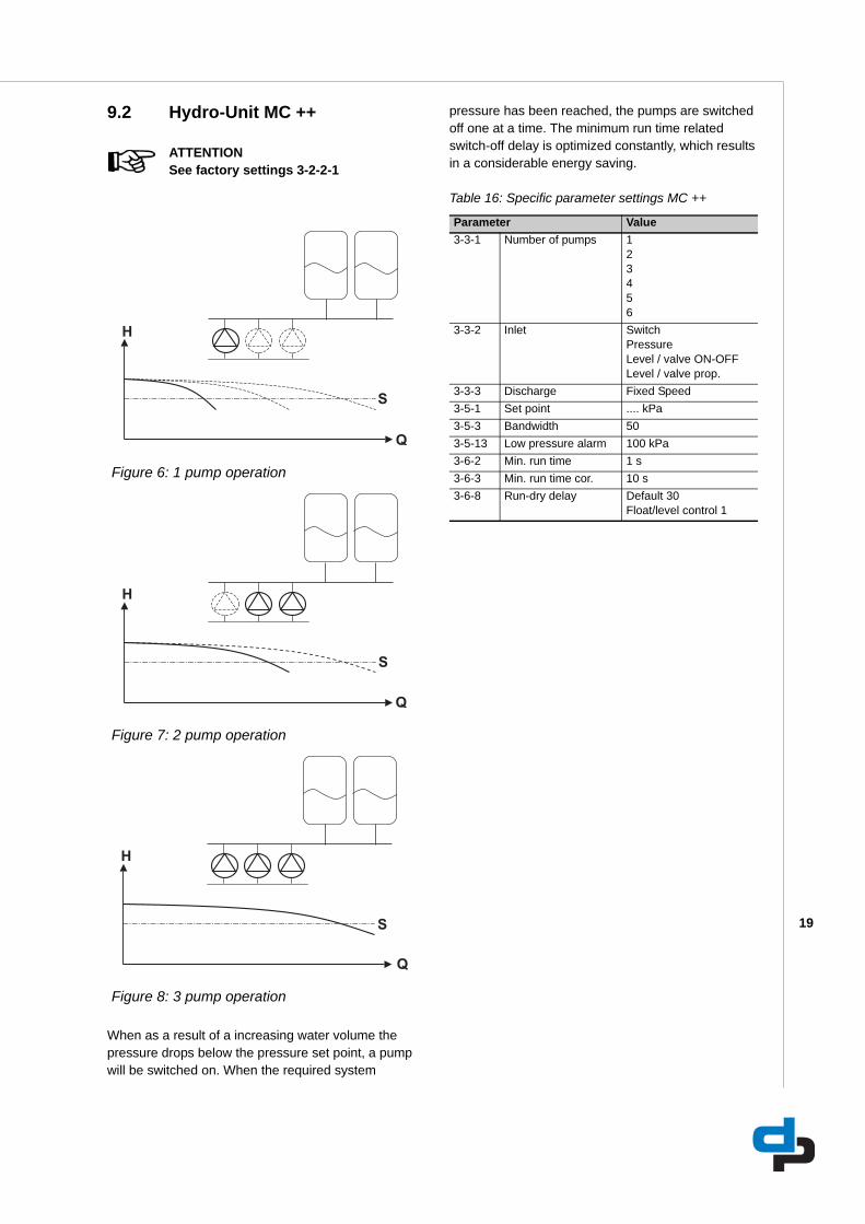
9.2 Hydro-Unit MC ++
ATTENTIONSee factory settings 3-2-2-1
When as a result of a increasing water volume the pressure drops below the pressure set point, a pump will be switched on. When the required system
pressure has been reached, the pumps are switched off one at a time. The minimum run time related switch-off delay is optimized constantly, which results in a considerable energy saving.
Table 16: Specific parameter settings MC ++
Figure 6: 1 pump operation
Figure 7: 2 pump operation
Figure 8: 3 pump operation
Parameter Value3-3-1 Number of pumps 1
23456
3-3-2 Inlet SwitchPressureLevel / valve ON-OFFLevel / valve prop.
3-3-3 Discharge Fixed Speed3-5-1 Set point .... kPa3-5-3 Bandwidth 503-5-13 Low pressure alarm 100 kPa3-6-2 Min. run time 1 s3-6-3 Min. run time cor. 10 s3-6-8 Run-dry delay Default 30
Float/level control 1

20
9.3 Hydro-Unit MCJ
ATTENTIONSee factory settings 3-2-2-1
The Hydro-Unit MCJ is fitted with a jockey pump, especially suited for installations with strongly fluctuating water consumption. The jockey pump is a smaller pump with less capacity but the same pressure as the main pumps of the installation. The jockey pump will be started first. If the water consumption is larger than the capacity of the jockey pump, one or more main pumps will be switched on, whereas the jockey pump is switched off. If the capacity of the main pumps is not sufficient, in case of a large water consumption, the jockey pump will also be switched on. A Hydro-Unit can also be fitted with 2 jockey pumps which are each other's backups.
Table 17: Specific parameter settings MCJ
Figure 9: 1 jockey pump operation
Figure 10: 1 main pump operation
Figure 11: 2 main pumps operation
Q
H
S
S
Q
H
S
Q
H
Parameter Value3-3-1 Number of pumps 1
23456
3-3-2 Inlet SwitchPressureLevel / valve ON-OFFLevel / valve prop.
3-3-3 Discharge One Jockey3-5-1 Set point .... kPa3-5-3 Bandwidth 303-6-2 Min. run time Default 180 s
DOL ≤ 2.2 kW 90 s3-6-3 Min. run time corr. 10 s3-6-8 Run-dry delay Default 30 s
Float/level control 1 s

21
9.4 Hydro-Unit MCF
ATTENTIONSee factory settings 3-2-2-1
The Hydro-Unit MCF is equipped with one variable frequency drive. If the Hydro-Unit is rotation-controlled, the required system pressure is sensed by a pressure sensor on the outlet side of the installation. An integrated adjustable PID-controller in the software of the Megacontrol ensures that the system pressure remains constant by successively switching on or off one or more (whether or not) rotation-controlled pumps with delay. A pump is only switched on when 100% or respectively 0% of the speed has been reached.
Table 18: Specific parameter settings MCF
Figure 12: 1 pump operation, 1 pump variable
Figure 13: 2 pump operation, 1 pump variable
Figure 14: 3 pump operation, 1 pump variable
Parameter Value3-3-1 Number of pumps 1
23456
3-3-2 Inlet SwitchPressureLevel / valve ON-OFFLevel / valve prop.
3-3-3 Discharge VFD change-over3-4-3-1 Communication Analog 0-20 mA3-4-3-2 Proportional const. 603-4-3-3 Integral const. 203-5-1 Set point .... kPa3-5-3 Bandwidth 53-5-4 Accumulation press. 30 kPa3-6-2 Min. run time 1 s3-6-3 Min. run time corr. 0 s3-6-8 Run-dry delay Default 30
Float/level control

22
9.5 Hydro-Unit MCMF
ATTENTIONSee factory settings 3-2-2-1
The Hydro-Unit MCMF is equipped with multiple variable frequency drives. If the Hydro-Unit is rotation-controlled, the required system pressure is sensed by a pressure sensor on the outlet side of the installation. An integrated adjustable PID-controller in the software of the Megacontrol ensures that the system pressure remains constant by successively switching on or off one or more (whether or not) rotation-controlled pumps with delay. A pump is only switched on when 100% or respectively 0% of the speed has been reached.
Table 19: Specific parameter settings MCMF
Figure 15: 1 pump operation, 1 pump variable
Figure 16: 2 pump operation, 2 pump variable
Figure 17: 3 pump operation, 3 pump variable
Parameter Value3-3-1 Number of pumps 1
23456
3-3-2 Inlet SwitchPressureLevel / valve ON-OFFLevel / valve prop.
3-3-3 Discharge VFD fixed all3-4-3-1 Communication Analog 4-20mA
Danfoss VLT 2800PumpDriveDanfoss MicroDriveDanfoss AquaDrive
3-4-3-2 Proportional const. 203-4-3-3 Integral const. 53-4-3-4 Differential const. 13-4-3-5-1 No flow detection
0-1000 kPa10
0-2500 kPa 203-4-3-5-3 No flow step 53-4-3-7 VFD Write slave nr. ID3-4-3-8 Serial com. active. Active3-5-1 Set point .... kPa3-5-3 Bandwidth 103-5-4 Accumulation press. 30 kPa3-5-13 Low pressure alarm 100 kPa3-6-2 Min. run time 10 s3-6-3 Min. run time corr. 0 s3-6-8 Run-dry delay Default 30
Float/level control 1

23
9.6 Hydro-Unit Level controlID2962/29052007
Figure 18: Megacontrol Level controlTable 20: Parameters supply valve ON/OFF
Table 21: Parameters supply valve prop.
Table 22: Parameters general.
Table 23: Parameters threshold
9.7 Explanation of parameters
9.7.1 Pressure settings set points
Figure 19: Pressure settings set points fixed speed Table 24: Pressure settings set points fixed speed
Table 25: Pressure settings set points variable speed
ID Parameter3-4-1-4-9 Supply valve ON/OFF
A 3-4-1-4-7 High water levelB 3-4-1-4-9-2 Level 1 closed
3-4-1-4-9-4 Level 1A closedC 3-4-1-4-9-1 Level 1 open
3-4-1-4-9-3 Level 1A openE 3-4-1-4-6 Critical water levelF 3-4-1-4-5 Low level resetG 3-4-1-4-4 Low level shutdown
ID Parameter3-4-1-4-10 Supply valve prop.
A 3-4-1-4-7 High water level3-4-1-4-10-1 Level setpoint 13-4-1-4-10-2 Level setpoint 1A
D 3-4-1-4-10-3 HysteresisE 3-4-1-4-6 Critical water levelF 3-4-1-4-5 Low level resetG 3-4-1-4-4 Low level shutdown
ID ParameterH 3-4-1-4-3 Sensor levelI 3-4-1-4-1 0% levelJ 3-4-1-4-2 100% level
ID Parameter3-4-1-4-8 Threshold
T 3-4-1-4-8-1 Threshold 1 ON3-4-1-4-8-2 Threshold 1 OFF3-4-1-4-8-3 Threshold 2 ON3-4-1-4-8-4 Threshold 2 OFF
ID ParameterS 3-5-1 Set pointA 3-5-3 BandwidthB Switch-off pressureC Switch-on pressureD 2 x bandwidth
ID3100
Figure 20: Pressure settings set points variable speed 31
00/3
1032
008
ID ParameterA 3-5-4 Accumulation pressureB 3-5-3 BandwidthC Switch-on pressure 1st pumpD Switch-off pressure last pumpS 3-5-1 Set point
Q
H
S
A B
C
D
Q
H
S
A
B
D
C

24
9.7.2 Delta P + correction
Table 26: Parameters set points
9.7.3 Delta P - correction
Table 27: Parameters set points
Figure 21: 1-pump operation
Figure 22: 2-pumps operation
Figure 23: 3-pumps operation
ID ParameterS 3-5-1 Set point+ 3-5-10 Delta P
SP = Set pointy = New set pointΔp = Delta P (always positive)n = Total number of pumps of the installationx = Number of pumps switched on
Figure 24: 1-pump operation
Figure 25: 2-pumps operation
Figure 26: 3-pumps operation
ID ParameterS 3-5-1 Set point- 3-5-10 Delta P
SP = Set pointy = New set pointΔp = Delta P (always positive)n = Total number of pumps of the installationx = Number of pumps switched on
25
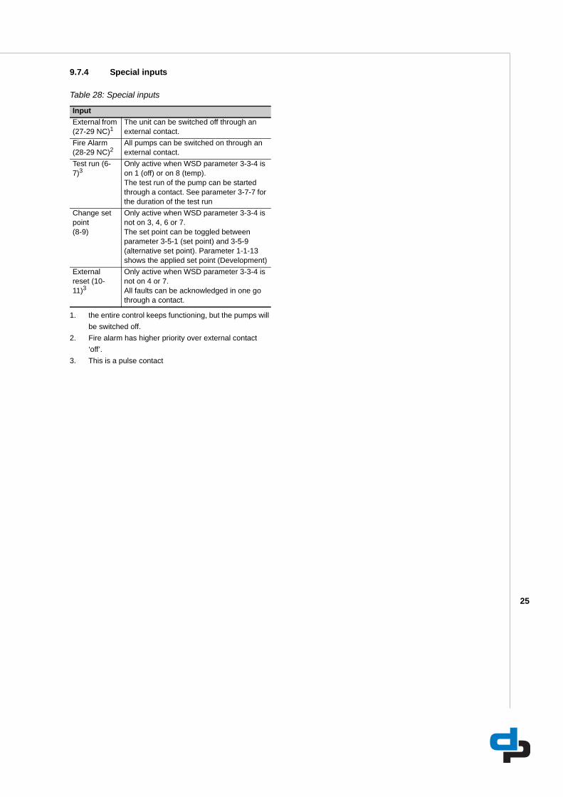
9.7.4 Special inputs
Table 28: Special inputs
InputExternal from (27-29 NC)1
1. the entire control keeps functioning, but the pumps will be switched off.
The unit can be switched off through an external contact.
Fire Alarm (28-29 NC)2
2. Fire alarm has higher priority over external contact ‘off’.
All pumps can be switched on through an external contact.
Test run (6-7)3
3. This is a pulse contact
Only active when WSD parameter 3-3-4 is on 1 (off) or on 8 (temp).The test run of the pump can be started through a contact. See parameter 3-7-7 for the duration of the test run
Change set point(8-9)
Only active when WSD parameter 3-3-4 is not on 3, 4, 6 or 7.The set point can be toggled between parameter 3-5-1 (set point) and 3-5-9 (alternative set point). Parameter 1-1-13 shows the applied set point (Development)
External reset (10-11)3
Only active when WSD parameter 3-3-4 is not on 4 or 7.All faults can be acknowledged in one go through a contact.

26
10 Parameters
10.1 Parameter list
The parameters of the main menu are related to the standard (default) settings of the installation. The standard (default) settings can be adjusted where necessary and may also be reset whenever required. On the basis of the standard set parameters, an
installation will operate as it should. Additional, extra parameters may be used, e.g. those under 'advanced', 'pressure', 'delays' and 'clock'. In order to use these additional parameters, you should activate the corresponding sub menus.
ATTENTIONFor unit-specific values see: 'Factory settings'.
ATTENTIONCertain parameters are not visible, depending on the configuration.
Table 29: Access level parameter list
10.1.1 Operation (Quick access button "pump")Table 30: Parameter list MCIII version 1.57 EN
Access level Read WriteEverybody e eUser c cService s sFactory f fNobody n
Para
met
er
Stan
dard
Min
Max
Rea
dW
rite
Hel
p te
xt
1 Operation e n Operating status and information 1-1 System e n Information on the operating status
and measurements of the complete system
1-1-1 System pressure 0 e n Actual system pressure (dis-charge side)
1-1-2 System load 0 e n Actual load in % of all pumps in operation (100% is one pump full speed)
1-1-3 RDP switch 0 not present,present e n Presence of a run dry protection signal by means of a pressure switch or float switch
1-1-4 Inlet pressure 0 e n Actual pressure at the inlet con-nection (suction side)
1-1-5 Level content in % 0 e n Actual water level in the receiver tank in % of the content (Storage tank at suction side)
1-1-6 Level height 0 e n Actual water height in the receiver tank (storage tank at suction side)

27
1-1-7 Ambient temp. (WSD) 0 e n Actual ambient temperature when temperature sensor is available (WSD functionality)
1-1-8 Digital inputs s s Displaying the activity status of all the digital inputs 0 = not active 1 = active
1-1-9 Position suppl.valve e n Position of the supply valve propor-tional 0% ... 100%
Position suppl.valve 0 open,closed e n Position of the supply valve 1 = open 2 = closed
1-1-10 Power down speed 0 s n Calculated power down speed if NFD is running in energy saving mode
1-1-11 state NFC 0 nfdMin,nfdInac-tive,nfdStable-Time,nfdGoingDown,nfdFinished,nfd-Max
d n Shows the current state of the no flow detection.
1-1-12 used setpoint 0 d n used setpoint 1-1-13 NTC Temperature 0 d n On board NTC temperature 1-1-14 WSD pulses tank 1 0 e n WSD Pulse count of the tank 1 1-1-15 WSD pulses tank 2 0 e n WSD Pulse count of the tank 2 1-1-16 WSD pulses tank 3 0 e n WSD Pulse count of the tank 3
1-2 Pumps e n Information on the operating status and measurements of the selected pump
1-2-1 Operating mode e e Displaying operating mode of the selected pump
Pump number 1 1 3 e e Selection of the pump of which the operating mode is required
Operating mode 1 Automatic,Manual (on 10s),Disabled (off)
e e Operating mode of the selected pump (continuous active) - Auto-matic - Manual (on) - Disabled (off)
1-2-2 Pump load e n Displaying the load of the selected pump
1-2-3 Thermal fail. flags s n Displaying the activity status of all thermal protection inputs 0 = not active 1 = active
1-2-4 Running hours pump e n Displaying the total running hours per pump in HHHHHH MM
1-2-5 Number of pumpstarts c n Displaying the total numbers of starts per pump
1-3 Time and statistics e n Operating time and statistics 1-3-1 Act runtime Op hours 0 e n Operating hours of the system in
HHHHHH 1-3-2 Time to service 0 e n Period of time until next service /
maintenance 1-3-3 Act Minimum Runtime 0 e n Actual minimum pump runtime in
seconds
1-4 Debugging f f
Para
met
er
Stan
dard
Min
Max
Rea
dW
rite
Hel
p te
xt
28
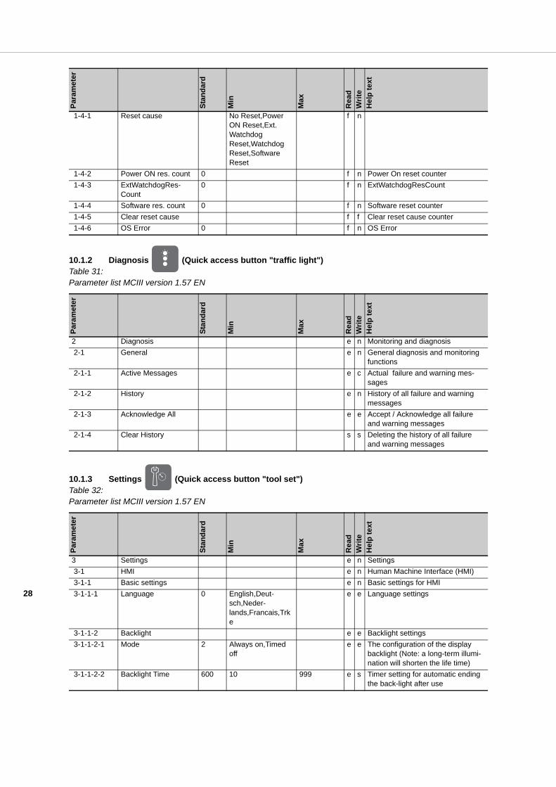
10.1.2 Diagnosis (Quick access button "traffic light")Table 31: Parameter list MCIII version 1.57 EN
10.1.3 Settings (Quick access button "tool set")Table 32: Parameter list MCIII version 1.57 EN
1-4-1 Reset cause No Reset,Power ON Reset,Ext. Watchdog Reset,Watchdog Reset,Software Reset
f n
1-4-2 Power ON res. count 0 f n Power On reset counter 1-4-3 ExtWatchdogRes-
Count0 f n ExtWatchdogResCount
1-4-4 Software res. count 0 f n Software reset counter 1-4-5 Clear reset cause f f Clear reset cause counter 1-4-6 OS Error 0 f n OS Error
Para
met
er
Stan
dard
Min
Max
Rea
dW
rite
Hel
p te
xt
2 Diagnosis e n Monitoring and diagnosis 2-1 General e n General diagnosis and monitoring
functions 2-1-1 Active Messages e c Actual failure and warning mes-
sages 2-1-2 History e n History of all failure and warning
messages 2-1-3 Acknowledge All e e Accept / Acknowledge all failure
and warning messages 2-1-4 Clear History s s Deleting the history of all failure
and warning messages
Para
met
er
Stan
dard
Min
Max
Rea
dW
rite
Hel
p te
xt
3 Settings e n Settings 3-1 HMI e n Human Machine Interface (HMI) 3-1-1 Basic settings e n Basic settings for HMI 3-1-1-1 Language 0 English,Deut-
sch,Neder-lands,Francais,Trke
e e Language settings
3-1-1-2 Backlight e e Backlight settings 3-1-1-2-1 Mode 2 Always on,Timed
offe e The configuration of the display
backlight (Note: a long-term illumi-nation will shorten the life time)
3-1-1-2-2 Backlight Time 600 10 999 e s Timer setting for automatic ending the back-light after use
Para
met
er
Stan
dard
Min
Max
Rea
dW
rite
Hel
p te
xt
29
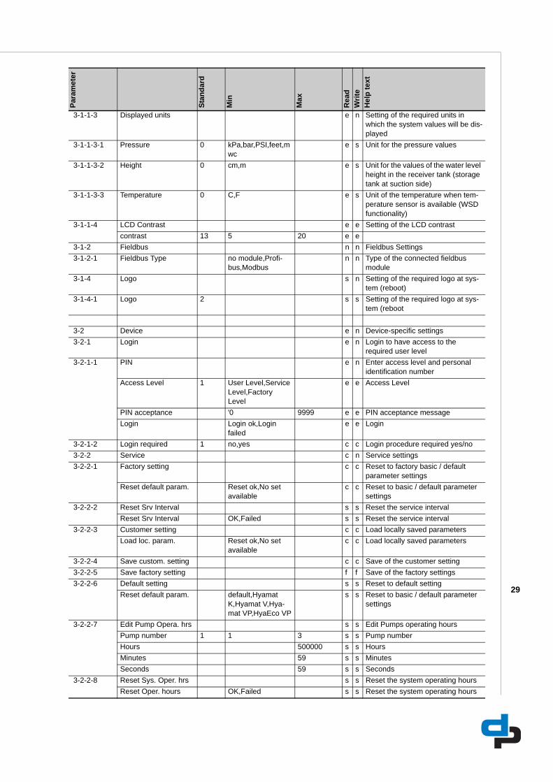
3-1-1-3 Displayed units e n Setting of the required units in which the system values will be dis-played
3-1-1-3-1 Pressure 0 kPa,bar,PSI,feet,mwc
e s Unit for the pressure values
3-1-1-3-2 Height 0 cm,m e s Unit for the values of the water level height in the receiver tank (storage tank at suction side)
3-1-1-3-3 Temperature 0 C,F e s Unit of the temperature when tem-perature sensor is available (WSD functionality)
3-1-1-4 LCD Contrast e e Setting of the LCD contrastcontrast 13 5 20 e e
3-1-2 Fieldbus n n Fieldbus Settings 3-1-2-1 Fieldbus Type no module,Profi-
bus,Modbusn n Type of the connected fieldbus
module 3-1-4 Logo s n Setting of the required logo at sys-
tem (reboot) 3-1-4-1 Logo 2 s s Setting of the required logo at sys-
tem (reboot
3-2 Device e n Device-specific settings 3-2-1 Login e n Login to have access to the
required user level 3-2-1-1 PIN e n Enter access level and personal
identification numberAccess Level 1 User Level,Service
Level,Factory Level
e e Access Level
PIN acceptance '0 9999 e e PIN acceptance messageLogin Login ok,Login
failede e Login
3-2-1-2 Login required 1 no,yes c c Login procedure required yes/no 3-2-2 Service c n Service settings 3-2-2-1 Factory setting c c Reset to factory basic / default
parameter settings Reset default param. Reset ok,No set
availablec c Reset to basic / default parameter
settings 3-2-2-2 Reset Srv Interval s s Reset the service interval
Reset Srv Interval OK,Failed s s Reset the service interval 3-2-2-3 Customer setting c c Load locally saved parameters
Load loc. param. Reset ok,No set available
c c Load locally saved parameters
3-2-2-4 Save custom. setting c c Save of the customer setting 3-2-2-5 Save factory setting f f Save of the factory settings 3-2-2-6 Default setting s s Reset to default setting
Reset default param. default,Hyamat K,Hyamat V,Hya-mat VP,HyaEco VP
s s Reset to basic / default parameter settings
3-2-2-7 Edit Pump Opera. hrs s s Edit Pumps operating hoursPump number 1 1 3 s s Pump numberHours 500000 s s HoursMinutes 59 s s MinutesSeconds 59 s s Seconds
3-2-2-8 Reset Sys. Oper. hrs s s Reset the system operating hoursReset Oper. hours OK,Failed s s Reset the system operating hours
Para
met
er
Stan
dard
Min
Max
Rea
dW
rite
Hel
p te
xt

30
3-2-3 Factory Test f n 3-2-3-1 Factory Test f f
Test result Failed,Passed f f
3-3 Configuration e n System configuration 3-3-1 Number of pumps 3 1 6 e s Total number of pumps in the sys-
tem 3-3-2 Inlet 1 Switch,Pres-
sure,Flow Con-trol,Level / valve on-off,Level / valve prop.
e s Setting of the applicable configura-tion at the inlet connection (suction side of the system)
3-3-3 Discharge 1 Fixed speed,One jockey,Two jockey,VFD chang-over,VFD fixed all
e s Setting of the applicable configura-tion at the discharge connection (pressure side of the system)
3-3-4 WSD 1 OFF,1 tank,2 tanks,3 tanks,1 tank + temp,2 tanks + temp,3 tanks + temp,Tem-perature
e s Setting of the applicable configura-tion of the WSD: (membrane tank refreshments and ambient temp.)
3-3-5 Leakage detection 2 ON,OFF e s Leakage detection 3-3-6 MPO Functionality 0 OFF,ON s s Synchron pump operation 3-3-7 PumpMode int/ext 0 Internal,External e s Pump mode is either Internaly (Via
HMI or Service) or externaly (via digital input) changed.
3-4 System settings e n System parameter settings 3-4-1 Inlet e n Parameter setting for the inlet con-
nection (suction side of the system) 3-4-1-1 Sensor press. 4 mA 0 -100 1000 e s Measured value at 4mA 3-4-1-2 Sensor press. 20 mA 1000 -100 9999 e s Measured value at 20mA 3-4-1-3 Damp. Time Inlet 200 100 2000 f f Damping time for smoothing the
measured value, to compensate peaks in the measured values
3-4-1-4 Level config e s Parameter setting for the level con-trol in the receiver tank (storage tank at suction side)
3-4-1-4-1 0% level 0 0 99 e s Lowest possible level in the receiver tank at which no air is sucked in. In relation to the bottom
3-4-1-4-2 100% level 200 0 999 e s Highest possible level in the receiver tank before overflow is trig-gered. In relation to the bottom.
3-4-1-4-3 Sensor level 0 -100 999 e s The position where the level sensor is located in the receiver tank. In relation to the bottom.
3-4-1-4-4 Low level shut down 10 0 99 e s Low water level to protect the pumps for dry running. (system shut down)
3-4-1-4-5 Low level reset 15 0 99 e s Reset level to reset the system after low level shut down
3-4-1-4-6 Critical water level 30 0 99 e s Critical level at which the tank threatens to become empty. (back-up storage left)
3-4-1-4-7 High water level 105 0 199 e s High water level at which the tank threatens to become over-full
Para
met
er
Stan
dard
Min
Max
Rea
dW
rite
Hel
p te
xt
31
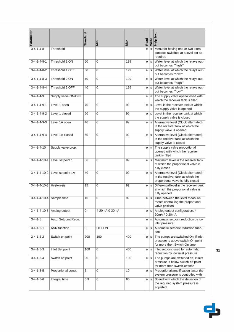
3-4-1-4-8 Threshold e s Menu for having one or two extra contacts switched at a level set as required
3-4-1-4-8-1 Threshold 1 ON 50 0 199 e s Water level at which the relays out-put becomes ""high""
3-4-1-4-8-2 Threshold 1 OFF 50 0 199 e s Water level at which the relays out-put becomes ""low""
3-4-1-4-8-3 Threshold 2 ON 40 0 199 e s Water level at which the relays out-put becomes ""high""
3-4-1-4-8-4 Threshold 2 OFF 40 0 199 e s Water level at which the relays out-put becomes ""low""
3-4-1-4-9 Supply valve ON/OFF e n The supply valve open/closed with which the receiver tank is filled
3-4-1-4-9-1 Level 1 open 70 0 99 e s Level in the receiver tank at which the supply valve is opened
3-4-1-4-9-2 Level 1 closed 90 0 99 e s Level in the receiver tank at which the supply valve is closed
3-4-1-4-9-3 Level 1A open 40 0 99 e s Alternative level (Clock alternated) in the receiver tank at which the supply valve is opened
3-4-1-4-9-4 Level 1A closed 60 0 99 e s Alternative level (Clock alternated) in the receiver tank at which the supply valve is closed
3-4-1-4-10 Supply valve prop. e n The supply valve proportional opened with which the receiver tank is filled
3-4-1-4-10-1 Level setpoint 1 80 0 99 e s Maximum level in the receiver tank at which the proportional valve is fully closed
3-4-1-4-10-2 Level setpoint 1A 40 0 99 e s Alternative level (Clock alternated) in the receiver tank at which the proportional valve is fully closed
3-4-1-4-10-3 Hysteresis 15 0 99 e s Differential level in the receiver tank at which the proportional valve is fully opened
3-4-1-4-10-4 Sample time 10 0 99 e s Time between the level measure-ments controlling the proportional valve position
3-4-1-4-10-5 Analog output 0 4-20mA,0-20mA e s Analog output configuration, 4-20mA / 0-20mA
3-4-1-5 Auto. Setpoint Redu. e n Automatic setpoint reduction by low inlet pressure
3-4-1-5-1 ASR function 0 OFF,ON e s Automatic setpoint reduction func-tion
3-4-1-5-2 Switch on point 200 100 400 e s The pumps are switched On, if inlet pressure is above switch-On point for more then Switch-On time
3-4-1-5-3 Inlet Set point 100 0 400 e s Inlet setpoint used for automatic reduction by low inlet pressure
3-4-1-5-4 Switch off point 90 0 100 e s The pumps are switched off, if inlet pressure is below switch-off point for more then switch-off time
3-4-1-5-5 Proportional const. 3 0 10 e s Proportional amplification factor the system pressure is controlled with
3-4-1-5-6 Integral time 0.9 0 60 e s Speed with which the deviation of the required system pressure is adjusted
Para
met
er
Stan
dard
Min
Max
Rea
dW
rite
Hel
p te
xt
32
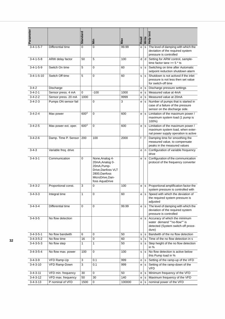
3-4-1-5-7 Differential time 0 0 99.99 e s The level of damping with which the deviation of the required system pressure is controlled
3-4-1-5-8 ARW delay factor 50 5 100 d d Setting for ARW control, sample-time factor tarw >= 5 * ts
3-4-1-5-9 Switch On time 5 0 60 s s Switching on time after Automatic setpoint reduction shutdown alarm
3-4-1-5-10 Switch Off time 5 0 60 s s Shutdown is not actived if the inlet pressure is not less then set value for switch-off time
3-4-2 Discharge e s Discharge pressure settings 3-4-2-1 Sensor press. 4 mA 0 -100 1000 e s Measured value at 4mA 3-4-2-2 Sensor press. 20 mA 1000 9999 e s Measured value at 20mA 3-4-2-3 Pumps ON sensor fail 0 3 e s Number of pumps that is started in
case of a failure of the pressure sensor on the discharge side.
3-4-2-4 Max power 6001 0 600 e s Limitation of the maximum power / maximum system load (1 pump is 100%)
3-4-2-5 Max power ext. oper. 6001 0 600 e s Limitation of the maximum power / maximum system load, when exter-nal power supply operation is active
3-4-2-6 Damp. Time P. Sensor 200 100 2000 f f Damping time for smoothing the measured value, to compensate peaks in the measured values
3-4-3 Variable freq. drive e n Configuration of variable frequency drive
3-4-3-1 Communication 0 None,Analog 4-20mA,Analog 0-20mA,Pump-Drive,Danfoss VLT 2800,Danfoss MicroDrive,Dan-foss AquaDrive
e s Configuration of the communication protocol of the frequency converter
3-4-3-2 Proportional const. 3 0 100 e s Proportional amplification factor the system pressure is controlled with
3-4-3-3 Integral time 1 0 60 e s Speed with which the deviation of the required system pressure is adjusted
3-4-3-4 Differential time 0 0 99.99 e s The level of damping with which the deviation of the required system pressure is controlled
3-4-3-5 No flow detection e s Accuracy of which the minimum water demand ""no-flow"" is detected (System switch-off proce-dure)
3-4-3-5-1 No flow bandwith 6 0 50 s s Bandwith of the no flow detection 3-4-3-5-2 No flow time 16 0 60 s s Time of the no flow detection in s 3-4-3-5-3 No flow step 1 1 50 s s Step height of the no flow detection
in % 3-4-3-5-4 No flow max. power 100 0 100 s s No flow detection is active below
this Pump load in % 3-4-3-9 VFD Ramp-Up 3 0.1 999 e s Setting of the ramp-up of the VFD 3-4-3-10 VFD Ramp-Down 3 0.1 999 e s Setting of the ramp-down of the
VFD 3-4-3-11 VFD min. frequency 30 0 50 e s Minimum frequency of the VFD 3-4-3-12 VFD max. frequency 50 30 140 e s Maximum frequency of the VFD 3-4-3-13 P nominal of VFD 1500 0 100000 e s nominal power of the VFD
Para
met
er
Stan
dard
Min
Max
Rea
dW
rite
Hel
p te
xt
33
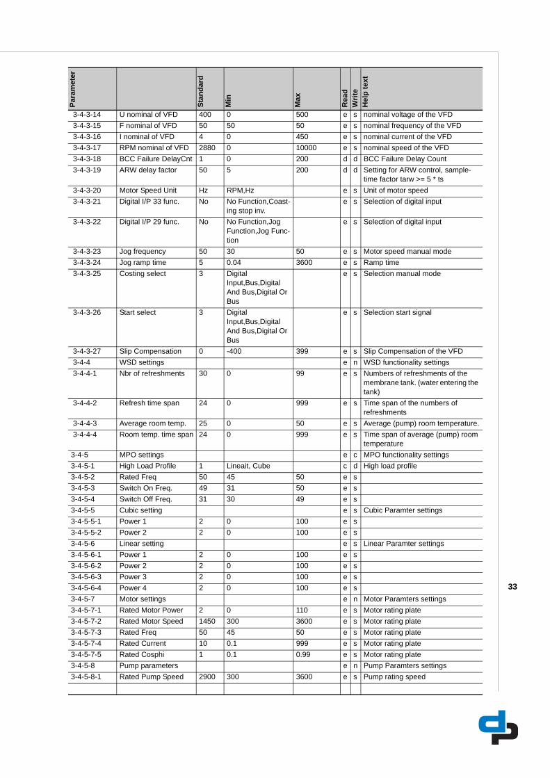
3-4-3-14 U nominal of VFD 400 0 500 e s nominal voltage of the VFD 3-4-3-15 F nominal of VFD 50 50 50 e s nominal frequency of the VFD 3-4-3-16 I nominal of VFD 4 0 450 e s nominal current of the VFD 3-4-3-17 RPM nominal of VFD 2880 0 10000 e s nominal speed of the VFD 3-4-3-18 BCC Failure DelayCnt 1 0 200 d d BCC Failure Delay Count 3-4-3-19 ARW delay factor 50 5 200 d d Setting for ARW control, sample-
time factor tarw >= 5 * ts 3-4-3-20 Motor Speed Unit Hz RPM,Hz e s Unit of motor speed 3-4-3-21 Digital I/P 33 func. No No Function,Coast-
ing stop inv.e s Selection of digital input
3-4-3-22 Digital I/P 29 func. No No Function,Jog Function,Jog Func-tion
e s Selection of digital input
3-4-3-23 Jog frequency 50 30 50 e s Motor speed manual mode 3-4-3-24 Jog ramp time 5 0.04 3600 e s Ramp time 3-4-3-25 Costing select 3 Digital
Input,Bus,Digital And Bus,Digital Or Bus
e s Selection manual mode
3-4-3-26 Start select 3 Digital Input,Bus,Digital And Bus,Digital Or Bus
e s Selection start signal
3-4-3-27 Slip Compensation 0 -400 399 e s Slip Compensation of the VFD 3-4-4 WSD settings e n WSD functionality settings 3-4-4-1 Nbr of refreshments 30 0 99 e s Numbers of refreshments of the
membrane tank. (water entering the tank)
3-4-4-2 Refresh time span 24 0 999 e s Time span of the numbers of refreshments
3-4-4-3 Average room temp. 25 0 50 e s Average (pump) room temperature. 3-4-4-4 Room temp. time span 24 0 999 e s Time span of average (pump) room
temperature3-4-5 MPO settings e c MPO functionality settings3-4-5-1 High Load Profile 1 Lineait, Cube c d High load profile3-4-5-2 Rated Freq 50 45 50 e s3-4-5-3 Switch On Freq. 49 31 50 e s3-4-5-4 Switch Off Freq. 31 30 49 e s3-4-5-5 Cubic setting e s Cubic Paramter settings3-4-5-5-1 Power 1 2 0 100 e s3-4-5-5-2 Power 2 2 0 100 e s3-4-5-6 Linear setting e s Linear Paramter settings3-4-5-6-1 Power 1 2 0 100 e s3-4-5-6-2 Power 2 2 0 100 e s3-4-5-6-3 Power 3 2 0 100 e s3-4-5-6-4 Power 4 2 0 100 e s3-4-5-7 Motor settings e n Motor Paramters settings3-4-5-7-1 Rated Motor Power 2 0 110 e s Motor rating plate3-4-5-7-2 Rated Motor Speed 1450 300 3600 e s Motor rating plate3-4-5-7-3 Rated Freq 50 45 50 e s Motor rating plate3-4-5-7-4 Rated Current 10 0.1 999 e s Motor rating plate3-4-5-7-5 Rated Cosphi 1 0.1 0.99 e s Motor rating plate3-4-5-8 Pump parameters e n Pump Paramters settings3-4-5-8-1 Rated Pump Speed 2900 300 3600 e s Pump rating speed
Para
met
er
Stan
dard
Min
Max
Rea
dW
rite
Hel
p te
xt
34
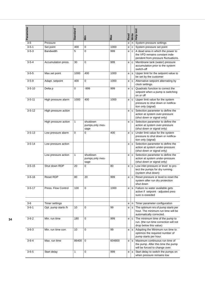
3-5 Pressure e n System pressure settings 3-5-1 Set point 400 0 1000 e c System pressure set point 3-5-3 Bandwidth 5 0 999 e c A dead area in which the power to
the VFD remains constant inde-pendent from pressure fluctuations.
3-5-4 Accumulation press. 30 0 999 e c Membrane tank (water) pressure accumulation prior to the system switch-off
3-5-5 Max.set point 1000 400 1000 e s Upper limit for the setpoint value to be set by the customer
3-5-9 Adapt. setpoint 400 0 1000 e c Alternative setpoint alternating by clock settings.
3-5-10 Delta p 0 -999 999 e c Quadratic function to correct the setpoint when a pump is switching on or off
3-5-11 High pressure alarm 1000 400 1000 e c Upper limit value for the system pressure to shut down or notifica-tion only (signal)
3-5-12 High pressure action e c Selection parameter to define the action at system over-pressure (shut down or signal only)
High pressure action 1 shutdown pumps,only mes-sage
e c Selection parameter to define the action at system over-pressure (shut down or signal only)
3-5-13 Low pressure alarm 0 0 400 e c Under limit value for the system pressure to shut down or notifica-tion only (signal)
3-5-14 Low pressure action e c Selection parameter to define the action at system under-pressure (shut down or signal only)
Low pressure action 1 shutdown pumps,only mes-sage
e c Selection parameter to define the action at system under-pressure (shut down or signal only)
3-5-15 Shut down RDP 20 0 80 e c Low inlet pressure or level to pro-tect the pumps for dry running. (system shut down)
3-5-16 Reset RDP 80 20 999 e c Reset pressure or level to reset the system after run dry protection shut down
3-5-17 Press. Flow Control 100 0 1000 e s Failure no water available gets active if setpoint - adjusted pres-sure is exeeded
3-6 Timer settings e n Timer parameter configuration 3-6-1 Opt. pump starts /h 10 0 99 e s The optimum nrs of pump starts per
hour. The minimum run time will be automatically corrected.
3-6-2 Min. run time 180 0 999 e c The minimum time of the pump to run. (the run time correction will not drop below this value)
3-6-3 Min. run time corr. 10 0 99 e s Adapting the Minimum run time to optimize the required number of pump starts per hour.
3-6-4 Max. run time 86400 0 604800 e s Maximum continuous run time of the pump. After this time the pump will be forced to change over.
3-6-5 Start delay 1 0 999 e s Start delay to switch the pumps on when pressure remains low
Para
met
er
Stan
dard
Min
Max
Rea
dW
rite
Hel
p te
xt
35
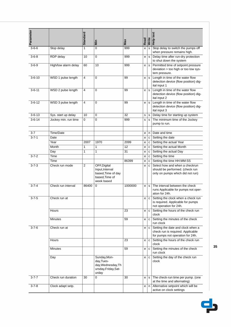
3-6-6 Stop delay 1 0 999 e s Stop delay to switch the pumps off when pressure remains high.
3-6-8 RDP delay 10 0 999 e s Delay time after run-dry protection to shut down the system
3-6-9 High/low alarm delay 60 10 999 e s Permitted time of setpoint pressure deviation > too high or too low sys-tem pressure.
3-6-10 WSD 1 pulse length 4 0 99 e s Length in time of the water flow detection device (flow position) dig-ital input 1
3-6-11 WSD 2 pulse length 4 0 99 e s Length in time of the water flow detection device (flow position) dig-ital input 2
3-6-12 WSD 3 pulse length 4 0 99 e s Length in time of the water flow detection device (flow position) dig-ital input 3
3-6-13 Sys. start up delay 10 0 32 s s Delay time for starting up system 3-6-14 Jockey min. run time 0 0 999 s s The minimum time of the Jockey
pump to run.
3-7 Time/Date e n Date and time 3-7-1 Date e c Setting the date
Year 2007 1970 2099 e c Setting the actual YearMonth 1 1 12 e c Setting the actual MonthDay 1 1 31 e c Setting the actual Day
3-7-2 Time e c Setting the timeTime 86399 e c Setting the time HH:MM:SS
3-7-3 Check run mode 2 OFF,Digital Input,Interval based,Time of day based,Time of week based
e c Select how and when a checkrun should be performed. (check run only on pumps which did not run)
3-7-4 Check run interval 86400 0 1000000 e s The interval between the check runs Applicable for pumps not oper-ation for 24h.
3-7-5 Check run at e c Setting the clock when a check run is required. Applicable for pumps not operation for 24h.
Hours 23 e c Setting the hours of the check run clock
Minutes 59 e c Setting the minutes of the check run clock
3-7-6 Check run at e c Setting the date and clock when a check run is required. Applicable for pumps not operation for 24h.
Hours 23 e c Setting the hours of the check run clock
Minutes 59 e c Setting the minutes of the check run clock
Day Sunday,Mon-day,Tues-day,Wednesday,Thursday,Friday,Sat-urday
e c Setting the day of the check run clock
3-7-7 Check run duration 30 0 30 e s The check-run time per pump. (one at the time and alternating)
3-7-8 Clock adapt setp. e n Alternative setpoint which will be active on clock settings
Para
met
er
Stan
dard
Min
Max
Rea
dW
rite
Hel
p te
xt
36
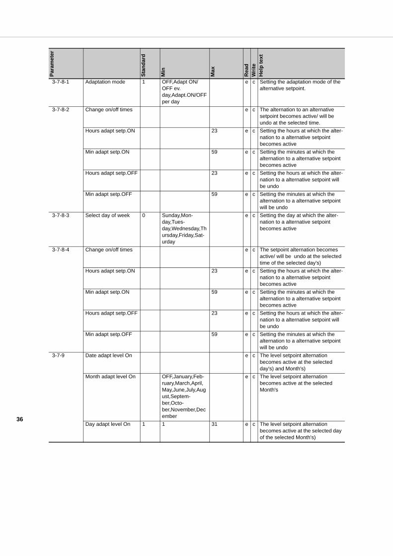
3-7-8-1 Adaptation mode 1 OFF,Adapt ON/OFF ev. day,Adapt.ON/OFF per day
e c Setting the adaptation mode of the alternative setpoint.
3-7-8-2 Change on/off times e c The alternation to an alternative setpoint becomes active/ will be undo at the selected time.
Hours adapt setp.ON 23 e c Setting the hours at which the alter-nation to a alternative setpoint becomes active
Min adapt setp.ON 59 e c Setting the minutes at which the alternation to a alternative setpoint becomes active
Hours adapt setp.OFF 23 e c Setting the hours at which the alter-nation to a alternative setpoint will be undo
Min adapt setp.OFF 59 e c Setting the minutes at which the alternation to a alternative setpoint will be undo
3-7-8-3 Select day of week 0 Sunday,Mon-day,Tues-day,Wednesday,Thursday,Friday,Sat-urday
e c Setting the day at which the alter-nation to a alternative setpoint becomes active
3-7-8-4 Change on/off times e c The setpoint alternation becomes active/ will be undo at the selected time of the selected day's)
Hours adapt setp.ON 23 e c Setting the hours at which the alter-nation to a alternative setpoint becomes active
Min adapt setp.ON 59 e c Setting the minutes at which the alternation to a alternative setpoint becomes active
Hours adapt setp.OFF 23 e c Setting the hours at which the alter-nation to a alternative setpoint will be undo
Min adapt setp.OFF 59 e c Setting the minutes at which the alternation to a alternative setpoint will be undo
3-7-9 Date adapt level On e c The level setpoint alternation becomes active at the selected day's) and Month's)
Month adapt level On OFF,January,Feb-ruary,March,April,May,June,July,August,Septem-ber,Octo-ber,November,December
e c The level setpoint alternation becomes active at the selected Month's
Day adapt level On 1 1 31 e c The level setpoint alternation becomes active at the selected day of the selected Month's)
Para
met
er
Stan
dard
Min
Max
Rea
dW
rite
Hel
p te
xt
37
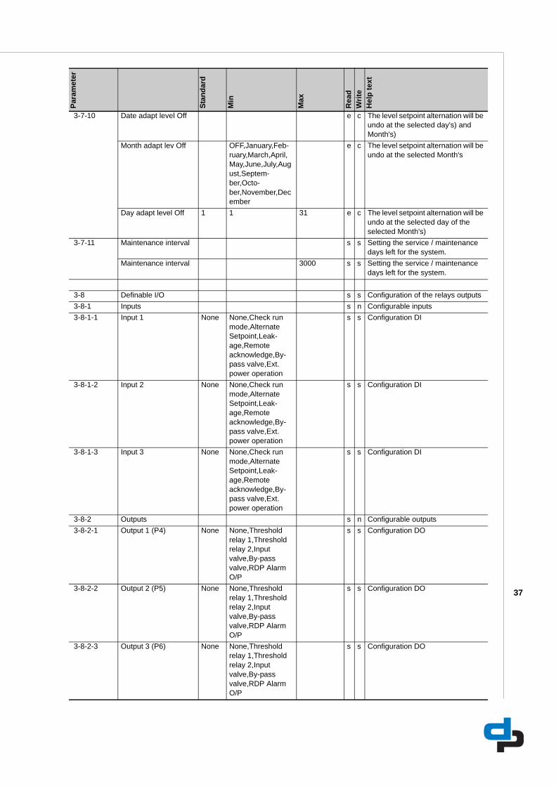
3-7-10 Date adapt level Off e c The level setpoint alternation will be undo at the selected day's) and Month's)
Month adapt lev Off OFF,January,Feb-ruary,March,April,May,June,July,August,Septem-ber,Octo-ber,November,December
e c The level setpoint alternation will be undo at the selected Month's
Day adapt level Off 1 1 31 e c The level setpoint alternation will be undo at the selected day of the selected Month's)
3-7-11 Maintenance interval s s Setting the service / maintenance days left for the system.
Maintenance interval 3000 s s Setting the service / maintenance days left for the system.
3-8 Definable I/O s s Configuration of the relays outputs 3-8-1 Inputs s n Configurable inputs 3-8-1-1 Input 1 None None,Check run
mode,Alternate Setpoint,Leak-age,Remote acknowledge,By-pass valve,Ext. power operation
s s Configuration DI
3-8-1-2 Input 2 None None,Check run mode,Alternate Setpoint,Leak-age,Remote acknowledge,By-pass valve,Ext. power operation
s s Configuration DI
3-8-1-3 Input 3 None None,Check run mode,Alternate Setpoint,Leak-age,Remote acknowledge,By-pass valve,Ext. power operation
s s Configuration DI
3-8-2 Outputs s n Configurable outputs 3-8-2-1 Output 1 (P4) None None,Threshold
relay 1,Threshold relay 2,Input valve,By-pass valve,RDP Alarm O/P
s s Configuration DO
3-8-2-2 Output 2 (P5) None None,Threshold relay 1,Threshold relay 2,Input valve,By-pass valve,RDP Alarm O/P
s s Configuration DO
3-8-2-3 Output 3 (P6) None None,Threshold relay 1,Threshold relay 2,Input valve,By-pass valve,RDP Alarm O/P
s s Configuration DO
Para
met
er
Stan
dard
Min
Max
Rea
dW
rite
Hel
p te
xt
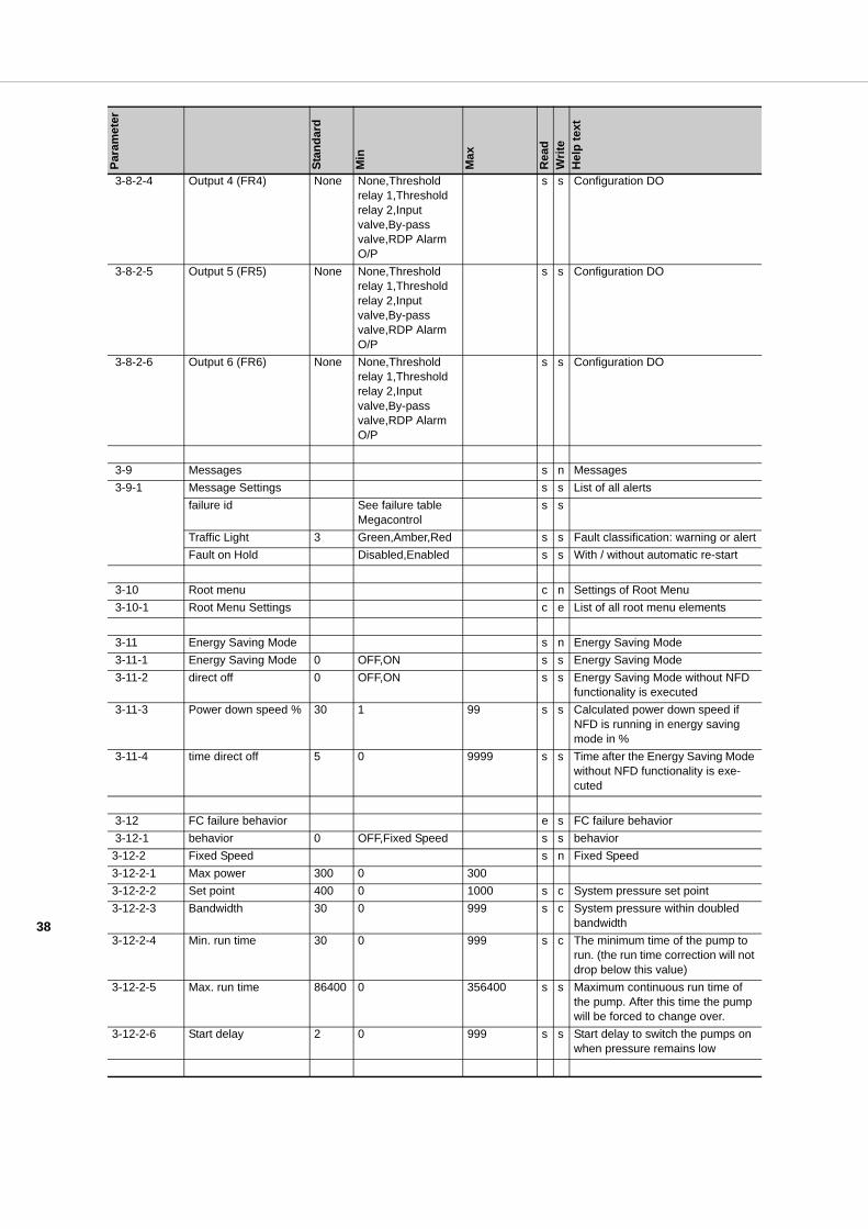
38
3-8-2-4 Output 4 (FR4) None None,Threshold relay 1,Threshold relay 2,Input valve,By-pass valve,RDP Alarm O/P
s s Configuration DO
3-8-2-5 Output 5 (FR5) None None,Threshold relay 1,Threshold relay 2,Input valve,By-pass valve,RDP Alarm O/P
s s Configuration DO
3-8-2-6 Output 6 (FR6) None None,Threshold relay 1,Threshold relay 2,Input valve,By-pass valve,RDP Alarm O/P
s s Configuration DO
3-9 Messages s n Messages 3-9-1 Message Settings s s List of all alerts
failure id See failure table Megacontrol
s s
Traffic Light 3 Green,Amber,Red s s Fault classification: warning or alertFault on Hold Disabled,Enabled s s With / without automatic re-start
3-10 Root menu c n Settings of Root Menu 3-10-1 Root Menu Settings c e List of all root menu elements
3-11 Energy Saving Mode s n Energy Saving Mode 3-11-1 Energy Saving Mode 0 OFF,ON s s Energy Saving Mode 3-11-2 direct off 0 OFF,ON s s Energy Saving Mode without NFD
functionality is executed 3-11-3 Power down speed % 30 1 99 s s Calculated power down speed if
NFD is running in energy saving mode in %
3-11-4 time direct off 5 0 9999 s s Time after the Energy Saving Mode without NFD functionality is exe-cuted
3-12 FC failure behavior e s FC failure behavior 3-12-1 behavior 0 OFF,Fixed Speed s s behavior3-12-2 Fixed Speed s n Fixed Speed3-12-2-1 Max power 300 0 3003-12-2-2 Set point 400 0 1000 s c System pressure set point3-12-2-3 Bandwidth 30 0 999 s c System pressure within doubled
bandwidth3-12-2-4 Min. run time 30 0 999 s c The minimum time of the pump to
run. (the run time correction will not drop below this value)
3-12-2-5 Max. run time 86400 0 356400 s s Maximum continuous run time of the pump. After this time the pump will be forced to change over.
3-12-2-6 Start delay 2 0 999 s s Start delay to switch the pumps on when pressure remains low
Para
met
er
Stan
dard
Min
Max
Rea
dW
rite
Hel
p te
xt
39
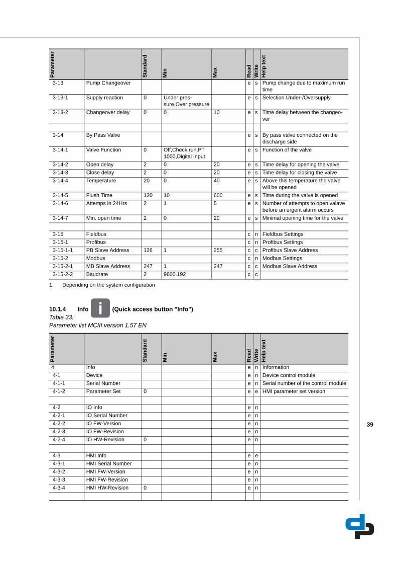
10.1.4 Info (Quick access button "Info")Table 33: Parameter list MCIII version 1.57 EN
3-13 Pump Changeover e s Pump change due to maximum run time
3-13-1 Supply reaction 0 Under pres-sure,Over pressure
e s Selection Under-/Oversupply
3-13-2 Changeover delay 0 0 10 e s Time delay between the changeo-ver
3-14 By Pass Valve e s By pass valve connected on the discharge side
3-14-1 Valve Function 0 Off,Check run,PT 1000,Digital Input
e s Function of the valve
3-14-2 Open delay 2 0 20 e s Time delay for opening the valve 3-14-3 Close delay 2 0 20 e s Time delay for closing the valve 3-14-4 Temperature 20 0 40 e s Above this temperature the valve
will be opened 3-14-5 Flush Time 120 10 600 e s Time during the valve is opened 3-14-6 Attemps in 24Hrs 2 1 5 e s Number of attempts to open valave
before an urgent alarm occurs 3-14-7 Min. open time 2 0 20 e s Minimal opening time for the valve
3-15 Fieldbus c n Fieldbus Settings 3-15-1 Profibus c n Profibus Settings 3-15-1-1 PB Slave Address 126 1 255 c c Profibus Slave Address 3-15-2 Modbus c n Modbus Settings 3-15-2-1 MB Slave Address 247 1 247 c c Modbus Slave Address 3-15-2-2 Baudrate 2 9600.192 c c
1. Depending on the system configuration
Para
met
er
Stan
dard
Min
Max
Rea
dW
rite
Hel
p te
xt
4 Info e n Information 4-1 Device e n Device control module 4-1-1 Serial Number e n Serial number of the control module 4-1-2 Parameter Set 0 e e HMI parameter set version
4-2 IO Info e n 4-2-1 IO Serial Number e n 4-2-2 IO FW-Version e n 4-2-3 IO FW-Revision e n 4-2-4 IO HW-Revision 0 e n
4-3 HMI Info e e 4-3-1 HMI Serial Number e n 4-3-2 HMI FW-Version e n 4-3-3 HMI FW-Revision e n 4-3-4 HMI HW-Revision 0 e n
Para
met
er
Stan
dard
Min
Max
Rea
dW
rite
Hel
p te
xt

40
10.1.5 Quick menu (Quick access button "OK")Table 34: Parameter list MCIII version 1.57 EN
4-4 Profibus Info e e 4-4-1 PB FW-Version e n 4-4-2 PB FW-Revision e n 4-4-3 PB HW-Revision 0 e n
4-5 Modbus Info e e 4-5-1 MB FW-Version e n 4-5-2 MB FW-Revision e n 4-5-3 MB HW-Revision 0 e n
Para
met
er
Stan
dard
Min
Max
Rea
dW
rite
Hel
p te
xt
3-2-1-1.1 PIN e n Enter access level and personal identification number
3-4-1-4-8-1 Threshold 1 ON 50 0 199 e s Water level at which the relays out-put becomes ""high""
3-4-1-4-8-2 Threshold 1 OFF 50 0 199 e s Water level at which the relays out-put becomes ""low""
3-4-1-4-8-3 Threshold 2 ON 40 0 199 e s Water level at which the relays out-put becomes ""high""
3-4-1-4-8-4 Threshold 2 OFF 40 0 199 e s Water level at which the relays out-put becomes ""low""
3-4-1-4-9-1 Level 1 open 70 0 99 e s Level in the receiver tank at which the supply valve is opened
3-4-1-4-9-2 Level 1 closed 90 0 99 e s Level in the receiver tank at which the supply valve is closed
3-4-1-4-10-1 Level setpoint 1 80 0 99 e s Maximum level in the receiver tank at which the proportional valve is fully closed
3-4-1-4-10-3 Hysteresis 15 0 99 e s Differential level in the receiver tank at which the proportional valve is fully opened
3-4-1-4-10-4 Sample time 10 0 99 e s Time between the level measure-ments controlling the proportional valve position
3-4-3-2 Proportional const. 3 0 100 e s Proportional amplification factor the system pressure is controlled with
3-4-3-3 Integral time 1 0 60 e s Speed with which the deviation of the required system pressure is adjusted
3-4-3-4 Differential time 0 99.99 e s The level of damping with which the deviation of the required system pressure is controlled
3-4-3-9 VFD Ramp-Up 3 0.1 999 e s Setting of the ramp-up of the VFD 3-4-3-10 VFD Ramp-Down 3 0.1 999 e s Setting of the ramp-down of the
VFD 3-4-3-27 Slip Compensation -400 399 e s Slip Compensation of the VFD
Para
met
er
Stan
dard
Min
Max
Rea
dW
rite
Hel
p te
xt
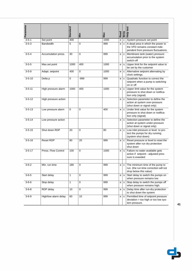
41
3-5-1 Set point 400 1000 e c System pressure set point 3-5-3 Bandwidth 5 0 999 e c A dead area in which the power to
the VFD remains constant inde-pendent from pressure fluctuations.
3-5-4 Accumulation press. 30 0 999 e c Membrane tank (water) pressure accumulation prior to the system switch-off
3-5-5 Max.set point 1000 400 1000 e s Upper limit for the setpoint value to be set by the customer
3-5-9 Adapt. setpoint 400 0 1000 e c Alternative setpoint alternating by clock settings.
3-5-10 Delta p 0 -999 999 e c Quadratic function to correct the setpoint when a pump is switching on or off
3-5-11 High pressure alarm 1000 400 1000 e c Upper limit value for the system pressure to shut down or notifica-tion only (signal)
3-5-12 High pressure action e c Selection parameter to define the action at system over-pressure (shut down or signal only)
3-5-13 Low pressure alarm 0 0 400 e c Under limit value for the system pressure to shut down or notifica-tion only (signal)
3-5-14 Low pressure action e c Selection parameter to define the action at system under-pressure (shut down or signal only)
3-5-15 Shut down RDP 20 0 80 e c Low inlet pressure or level to pro-tect the pumps for dry running. (system shut down)
3-5-16 Reset RDP 80 20 999 e c Reset pressure or level to reset the system after run dry protection shut down
3-5-17 Press. Flow Control 100 0 1000 e s Failure no water available gets active if setpoint - adjusted pres-sure is exeeded
3-6-2 Min. run time 180 0 999 e c The minimum time of the pump to run. (the run time correction will not drop below this value)
3-6-5 Start delay 1 0 999 e s Start delay to switch the pumps on when pressure remains low
3-6-6 Stop delay 1 0 999 e s Stop delay to switch the pumps off when pressure remains high.
3-6-8 RDP delay 10 0 999 e s Delay time after run-dry protection to shut down the system
3-6-9 High/low alarm delay 60 10 999 e s Permitted time of setpoint pressure deviation > too high or too low sys-tem pressure.
Para
met
er
Stan
dard
Min
Max
Rea
dW
rite
Hel
p te
xt

42
11 Faults
11.1 Failure messages Megacontrol
Table 35: Faults list Megacontrol
Failure message: Explanation: Failureoutput:
Failure PT. Dis. Failure Pressure Transmitter discharge side (value >20mA) replace PT and reset system UrgentSys. press.to low System pressure too long under minimum value (3-5-13) Urgent1
Sys press.to high System pressure too long above maximum value (3-5-11) Urgent1
Sys. press.to low System pressure too long under minimum value (3-5-13) Non urgent2
Sys press.to high System pressure too long above maximum value (3-5-11) Non urgent2
No water No sufficient water or -pressure available at suction side Urgent1
No water No sufficient water or -pressure available at suction side Non urgent2
Maintenance req. Maintenance is required Non urgentMore pumps fail More than two pumps out of order UrgentNo refresh tank # No water refreshm in tank # (sensed by the flow detector) check precharged air pressure UrgentAver temp to high Average room temperature to high (sensed by the temperature sensor) UrgentCurr temp to high Current room temperature to high (sensed by the temperature sensor) Non urgentTemp.failure Pump # Failure pump #. Solve problem and reset the system Non urgentFailure valve Failure supply valve. Solve problem and reset the system UrgentInlet sensor fail Failure inlet Sensor for level or pressure. (signal out of range) replace Sensor and reset
system.Urgent
High water level Water level in receiver tank too high Non urgentCrit. water level Water level in receiver tank critical (near to empty) Non urgentLow water level Water level in receiver tank too low (system shut down for run dry protection) Urgent1
Low water level Water level in receiver tank too low (system shut down for run dry protection) Non urgent2
Comm. Error FC # Communication to variable frequency drive # is broken Non urgentIncor. check sum F # FC # Incorrect check sum within the protocol Non urgentTemp. sensor fail Failure Room Temperature Sensor. replace R.T.S. and reset system Non urgent24V out of range Failure message due to internal 24V supply out of range Non urgent5V out of range failure message due to internal 5V supply out of range Non urgent3V out of range Failure message due to internal 3V supply out of range Non urgentExternal off Failure message due to an external off command UrgentFire alarm Failure message due to an external fire alarm command UrgentFailure VFD Failure of the VFD drive at discharge mode VFD change-over or VFD fixed one UrgentBr. Wire Sens.dis Failure Pressure Transmitter discharge side (value lower then 4mA) connect or replace
Pressure Transmitter and reset systemUrgent
Br. Wire Sens.Inl Failure inlet Sensor for level or pressure. (wire break detection) Replace Sensor and reset system.
Urgent
Fail. several FCs Failure for more than one FC occurs UrgentLeakage There is a leakage in the unit. Solve problem and reset the system UrgentEeprom HW Error The Eeprom data was not saved due to HW problem UrgentManual off Pump # off
Not urgent
Manual On Pump # Not urgentMore Pumps off Not urgentInternal Failure P# Not urgentMains Failure P# Not urgentOver voltageP# Not urgentUnder voltage P# Not urgentOverload Failure P# Not urgentBrake resistor P# Not urgent

43
11.2 Failure messages Danfoss VFD
ATTENTIONThe error codes are displayed in the error log of the Megacontrol. For specific information about the error codes please consult the (technical) documentation of the VFD concerned.
Table 36: VLT 2800
Temp. Failure P# Not urgentATM Failure P# Not urgentFlushing Not urgentValve opened oftenly
Urgent
Circuit Fail. FC# Not urgentExt. Power Opera-tion
External power supply operation Not urgent
Setpoint Reduction Automatic Setpoint Reduction because of inlet pressure dropdown Not urgentFactory Test Not urgentMPO Failure Incorrect switching point configured or sensor failure Not urgentASR Shutdown Automatic Setpoint Reduction Shutdown because of inlet pressure dropdown UrgentOccured: Failures that have occurred recently.Acknowledged: Failures that got acknowledged.Cleared: Failures that got clearedData:No failures
1. Manual alarm reset = Urgent.2. Automatic alarm reset = Non urgent.
Failure message: Explanation: Failureoutput:
Error code: Explanation: Warning: Alarm: Trip lock:2 Live zero error (LIVE ZERO ERROR) x x x4 Mains phase loss (MAINS PHASE LOSS) x x x5 Voltage warning high (DC LINK VOLTAGE HIGH) x6 Voltage warning low (DC LINK VOLTAGE LOW) x7 Overvoltage (DC LINK OVERVOLTAGE) x x x8 Undervoltage (DC LINK UNDERVOLT) x x x9 Inverter overload (INVERTER TIME) x x10 Motor overloaded (MOTOR TIME) x x11 Motor thermistor (MOTOR THERMISTOR) x x12 Current limit (CURRENT LIMIT) x x13 Overcurrent (OVERCURRENT) x x x14 Earth fault (EARTH FAULT) x x15 Switch mode fault (SWITCH MODE FAULT) x x16 Short-circuit (CURR. SHORT CIRCUIT) x x17 Serial communication timeout (STD BUS TIMEOUT) x x18 HPFB bus timeout (HPFB TIMEOUT) x x33 Out of frequency range (OUT FREQ RNG/ROT LIM) x34 HPFB communication fault (PROFIBUS OPT. FAULT) x x35 Inrush fault (INRUSH FAULT) x x36 Overtemperature (OVERTEMPERATURE) x x37-45 Internal fault (INTERNAL FAULT) x x50 AMT not possible x

44
Table 37: VLT Aquadrive FC200
51 AMT fault re. nameplate data (AMT TYPE. DATA FAULT) x54 AMT wrong motor (AMT WRONG MOTOR) x55 AMT timeout (AMT TIMEOUT) x56 AMT warning during AMT (AMT WARN. DURING AMT) x99 Locked (LOCKED) x
Error code: Explanation: Warning: Alarm/Trip: Alarm/Trip Lock:1 10 Volts low X2 Live zero error (X) (X)3 No motor (X)4 Mains phase loss X5 DC link voltage high X6 DC link voltage low X7 DC over voltage X X8 DC under voltage X X9 Inverter overloaded X X10 Motor overload temperature (X) (X)11 Motor thermistor over temperature (X) (X)12 Torque limit X X13 Over Current X X X14 Earth fault X X X15 Hardware mismatch X X16 Short Circuit X X17 Control word time out (X) (X)23 Internal fan fault X24 External fan fault X25 Brake resistor short-circuit X26 Brake resistor power limit (X) (X)27 Brake chopper fault X X28 Brake check failed (X) (X)29 Heatsink temp X X X30 Motor phase U missing (X) (X) (X)31 Motor phase V missing (X) (X) (X)30 Motor phase W missing (X) (X) (X)33 Inrush fault X X34 Field bus communication fault X X35 Out of frequency range X X36 Mains failure X X37 Phase imbalance X X38 Internal fault39 Heatsink sensor X X40 Overload of digital output terminal 27 (X)41 Overload of Digital Output Terminal 29 (X)42 Overload of Digital Output On X30/6 or overload of digital out-
put on X30/7(X)
46 Power card supply X X47 24 V supply low X X X48 1.8 V supply low X X49 Speed limit X50 AMA calibration failed X51 AMA check Unom and Inom X52 AMA low Inom X53 AMA motor too big X54 AMA motor too small X55 AMA parameter out of range X
Error code: Explanation: Warning: Alarm: Trip lock:
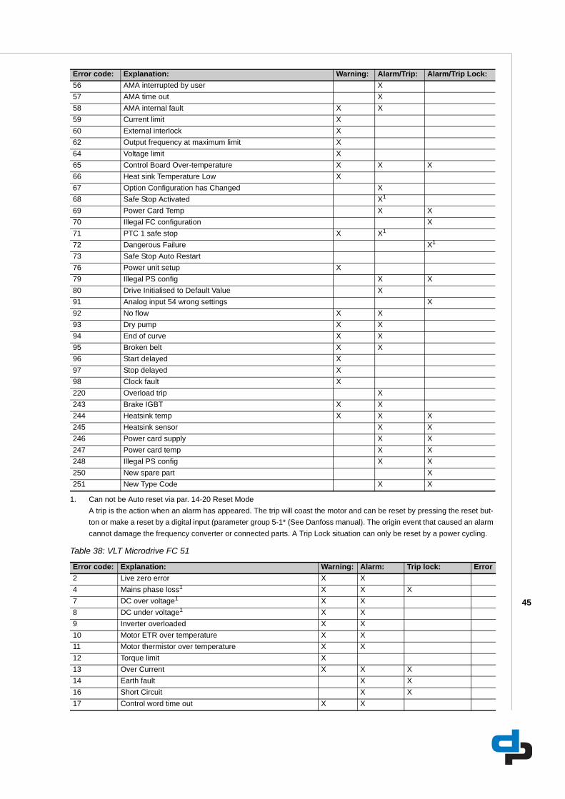
45
Table 38: VLT Microdrive FC 51
56 AMA interrupted by user X57 AMA time out X58 AMA internal fault X X59 Current limit X60 External interlock X62 Output frequency at maximum limit X64 Voltage limit X65 Control Board Over-temperature X X X66 Heat sink Temperature Low X67 Option Configuration has Changed X68 Safe Stop Activated X1
69 Power Card Temp X X70 Illegal FC configuration X71 PTC 1 safe stop X X1
72 Dangerous Failure X1
73 Safe Stop Auto Restart76 Power unit setup X79 Illegal PS config X X80 Drive Initialised to Default Value X91 Analog input 54 wrong settings X92 No flow X X93 Dry pump X X94 End of curve X X95 Broken belt X X96 Start delayed X97 Stop delayed X98 Clock fault X220 Overload trip X243 Brake IGBT X X244 Heatsink temp X X X245 Heatsink sensor X X246 Power card supply X X247 Power card temp X X248 Illegal PS config X X250 New spare part X251 New Type Code X X
1. Can not be Auto reset via par. 14-20 Reset ModeA trip is the action when an alarm has appeared. The trip will coast the motor and can be reset by pressing the reset but-ton or make a reset by a digital input (parameter group 5-1* (See Danfoss manual). The origin event that caused an alarm cannot damage the frequency converter or connected parts. A Trip Lock situation can only be reset by a power cycling.
Error code: Explanation: Warning: Alarm: Trip lock: Error2 Live zero error X X4 Mains phase loss1 X X X7 DC over voltage1 X X8 DC under voltage1 X X9 Inverter overloaded X X10 Motor ETR over temperature X X11 Motor thermistor over temperature X X12 Torque limit X13 Over Current X X X14 Earth fault X X16 Short Circuit X X17 Control word time out X X
Error code: Explanation: Warning: Alarm/Trip: Alarm/Trip Lock:
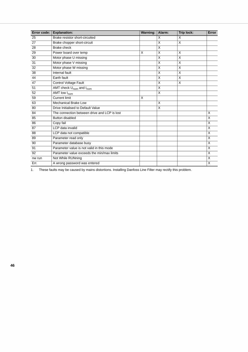
46
25 Brake resistor short-circuited X X27 Brake chopper short-circuit X X28 Brake check X29 Power board over temp X X X30 Motor phase U missing X X31 Motor phase V missing X X32 Motor phase W missing X X38 Internal fault X X44 Earth fault X X47 Control Voltage Fault X X51 AMT check Unom and Inom X52 AMT low Inom X59 Current limit X63 Mechanical Brake Low X80 Drive Initialised to Default Value X84 The connection between drive and LCP is lost X85 Button disabled X86 Copy fail X87 LCP data invalid X88 LCP data not compatible X89 Parameter read only X90 Parameter database busy X91 Parameter value is not valid in this mode X92 Parameter value exceeds the min/max limits Xnw run Not While RUNning XErr. A wrong password was entered X
1. These faults may be caused by mains distortions. Installing Danfoss Line Filter may rectify this problem.
Error code: Explanation: Warning: Alarm: Trip lock: Error
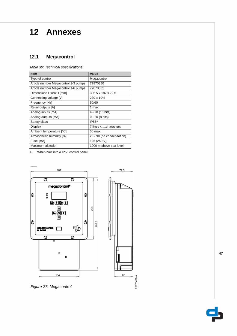
47
12 Annexes
12.1 Megacontrol
Table 39: Technical specifications
Item ValueType of control MegacontrolArticle number Megacontrol 1-3 pumps 77870350Article number Megacontrol 1-6 pumps 77870351Dimensions HxWxD [mm] 306.5 x 187 x 72.5Connecting voltage [V] 230 ± 10%Frequency [Hz] 50/60Relay outputs [A] 1 max.Analog inputs [mA] 4 - 20 (10 bits)Analog outputs [mA] 0 - 20 (8 bits)Safety class IP551
1. When built into a IP55 control panel.
Display 7 lines x ....charactersAmbient temperature [°C] 50 max.Atmospheric humidity [%] 20 - 90 (no condensation)Fuse [mA] 125 (250 V)Maximum altitude 1000 m above sea level
ID2986/07062007
Figure 27: Megacontrol 2007
0476
-A
187
134
306.
5
204
72.5
62
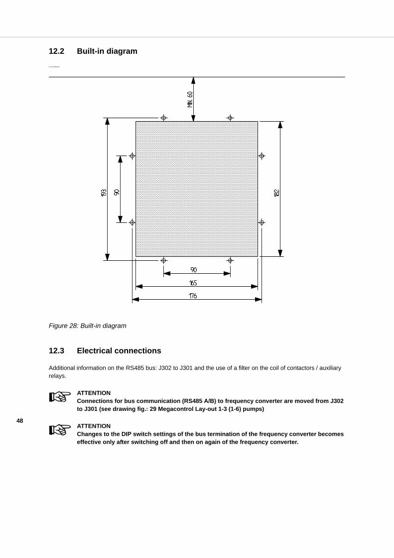
48
12.2 Built-in diagramID 2970/29052007
Figure 28: Built-in diagram
12.3 Electrical connections
Additional information on the RS485 bus: J302 to J301 and the use of a filter on the coil of contactors / auxiliary relays.
ATTENTIONConnections for bus communication (RS485 A/B) to frequency converter are moved from J302 to J301 (see drawing fig.: 29 Megacontrol Lay-out 1-3 (1-6) pumps)
ATTENTIONChanges to the DIP switch settings of the bus termination of the frequency converter becomes effective only after switching off and then on again of the frequency converter.

49
ID2971/07062007
Figure 29: Megacontrol Lay-out 1-3 (1-6) pumps**TRHX refers to table 40 Electrical connections 20
1100
97
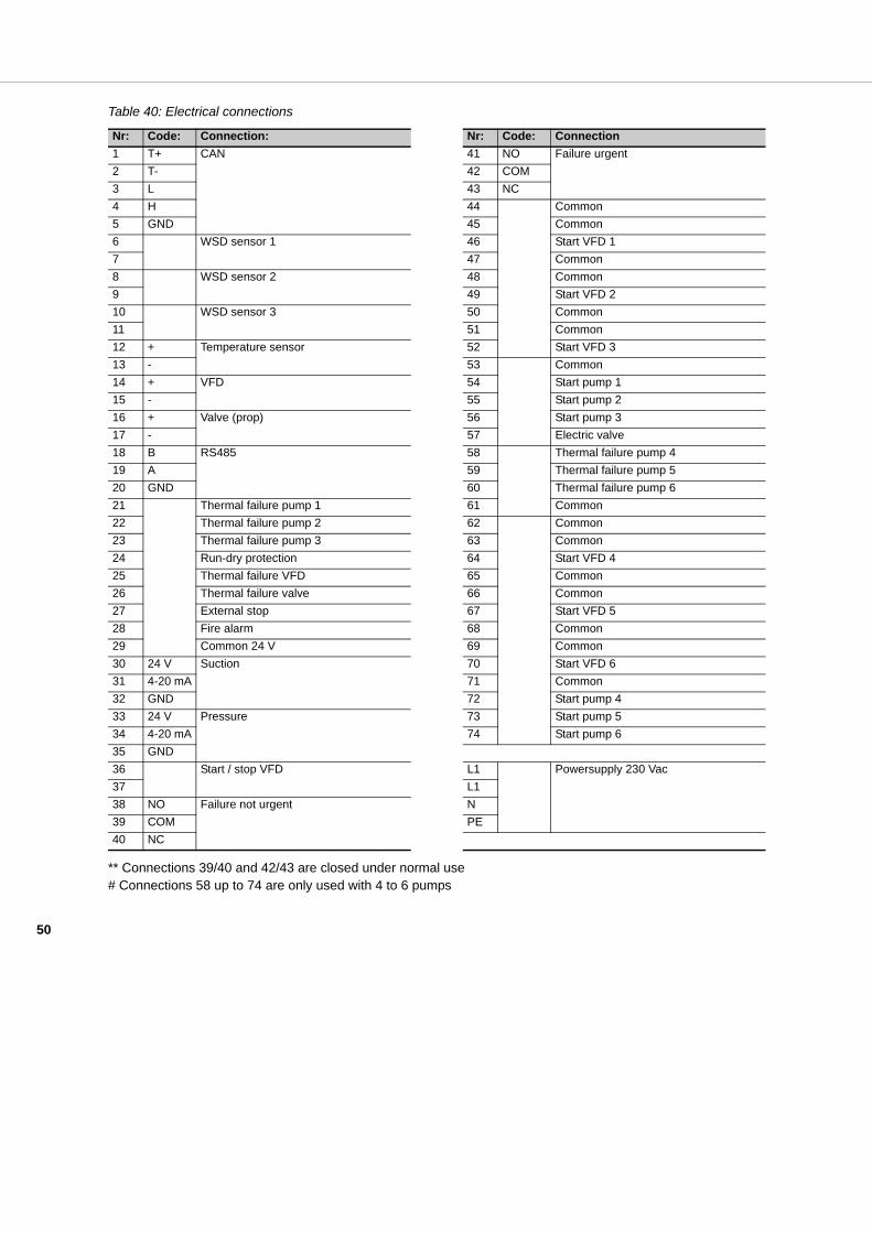
50
Table 40: Electrical connections
** Connections 39/40 and 42/43 are closed under normal use# Connections 58 up to 74 are only used with 4 to 6 pumps
Nr: Code: Connection: Nr: Code: Connection1 T+ CAN 41 NO Failure urgent2 T- 42 COM3 L 43 NC4 H 44 Common5 GND 45 Common6 WSD sensor 1 46 Start VFD 17 47 Common8 WSD sensor 2 48 Common9 49 Start VFD 210 WSD sensor 3 50 Common11 51 Common12 + Temperature sensor 52 Start VFD 313 - 53 Common14 + VFD 54 Start pump 115 - 55 Start pump 216 + Valve (prop) 56 Start pump 317 - 57 Electric valve18 B RS485 58 Thermal failure pump 419 A 59 Thermal failure pump 520 GND 60 Thermal failure pump 621 Thermal failure pump 1 61 Common22 Thermal failure pump 2 62 Common23 Thermal failure pump 3 63 Common24 Run-dry protection 64 Start VFD 425 Thermal failure VFD 65 Common26 Thermal failure valve 66 Common27 External stop 67 Start VFD 528 Fire alarm 68 Common29 Common 24 V 69 Common30 24 V Suction 70 Start VFD 631 4-20 mA 71 Common32 GND 72 Start pump 433 24 V Pressure 73 Start pump 534 4-20 mA 74 Start pump 635 GND36 Start / stop VFD L1 Powersupply 230 Vac37 L138 NO Failure not urgent N39 COM PE40 NC

51
12.4 EC Declaration of conformity
Undersigned:
DP-PumpsKalkovenweg 132401 LJ Alphen aan den Rijn, The NetherlandsTel: (+31)(0)-172-48 83 88Fax: (+31)(0)-172-46 89 30
Declares as manufacturer entirely on his own responsibility, that the product(s):
Product: Control unitType: Megacontrol
to which this declaration refers, is in accordance with the following standards:
- EN 61000-6-1- EN 61000-6-3- EN 61000-6-4
according to the provisions of (when applicable):
- Low voltage directive 2006/95/EC- EMC directive 2004/108/6/EC
If the control unit is used as a stand-alone product, it is subject to this declaration of conformity.
If the control unit is built in an appliance or is assembled together with other equipment in certain installations, then it should not be put into operation until a declaration has been given with respect to the appliance concerned that it complies with the directives listed above.
Alphen aan den Rijn,03/11/2014
Responsible person:W. Ouwehand, technical director

DP pumps
DP pumpsP.O. Box 282400 AA Alphen aan den Rijn (NL)
t (+31-172) 48 83 88f (+31-172) 46 89 30
11/2014
BE00000508
Original instructions
Can be changed without prior notice